

Scope
Size and select a cold climate heat pump:
- Understand the goals of the homeowner.
- Determine a sizing approach based on those goals.
- Choose a system configuration.
- Perform heating and cooling load calculations using ACCA Manual J.
- Determine target heating and cooling capacities using ACCA Manual S (3rd edition) and/or other methods.
- Select a cold climate heat pump that meets heating capacity goals without excessive cycling in heating or cooling.
See the Compliance Tab for links to related codes and standards and voluntary federal energy-efficiency program requirements.
Description
This guide describes sizing methods for cold climate heat pumps. It is assumed that the reader already has a basic understanding of HVAC systems and heating and cooling load calculations. Consider reading the “Traditional Split Heat Pumps” and “Ductless (Mini-Split) Heat Pumps” guides for background information.
What is a Cold Climate Heat Pump?
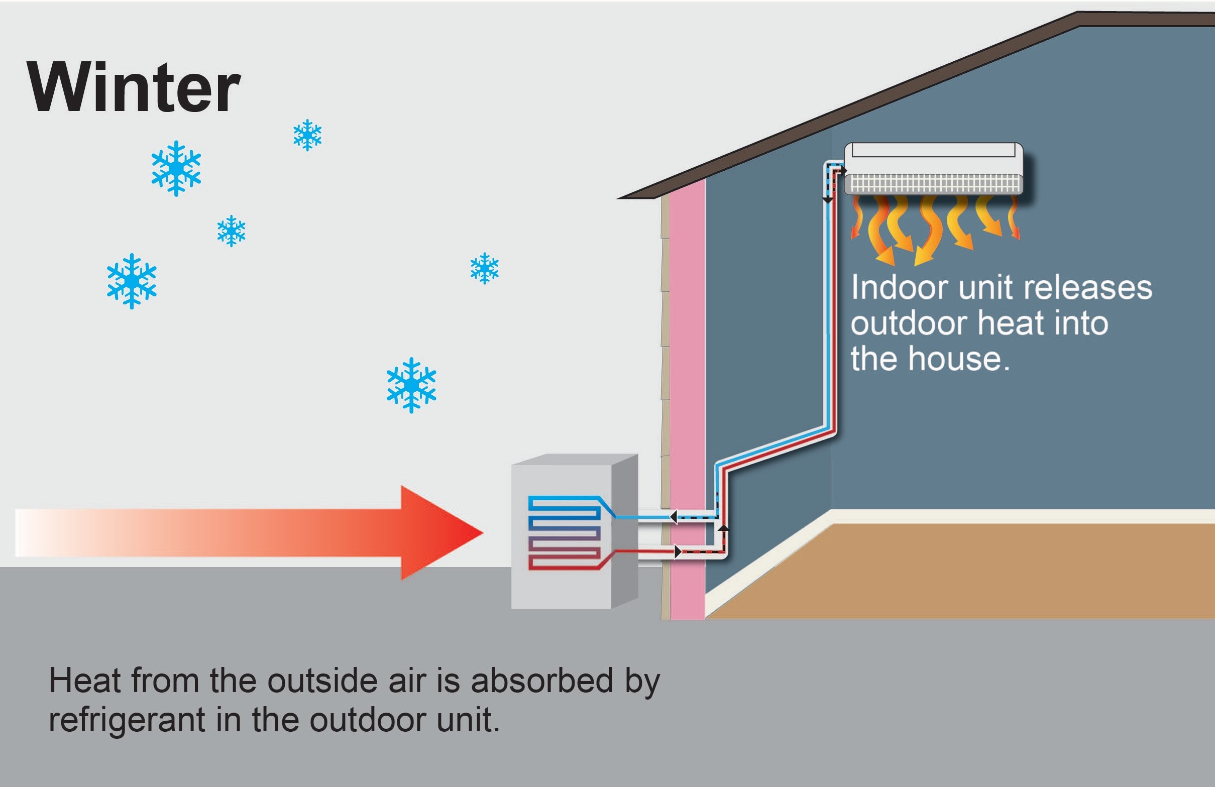
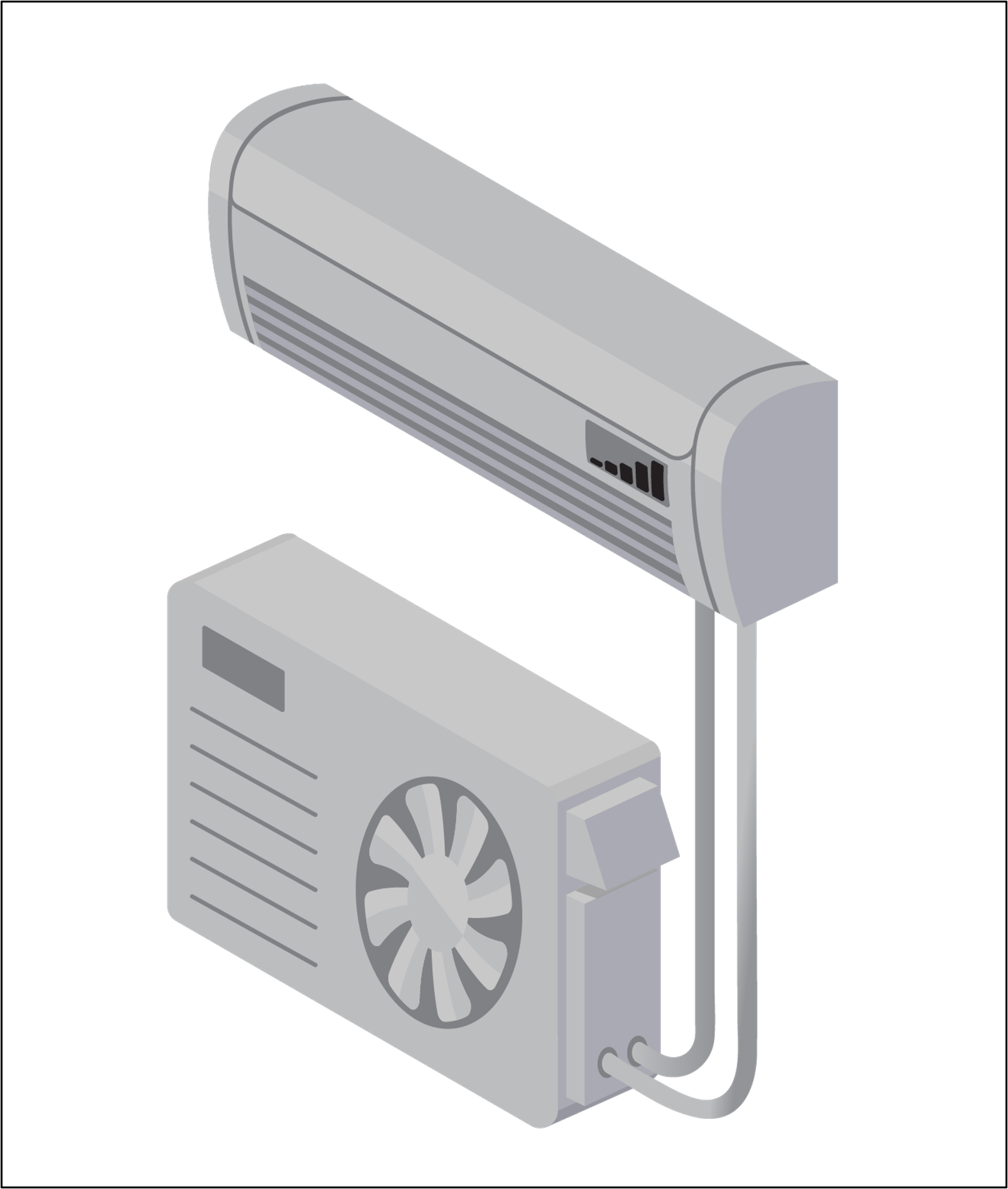
All air, even when it is very cold, contains some heat. Heat pumps provide heat by extracting heat from cold outside air and “pumping” it into the home (Figure 1). However, the colder it is outside, the more difficult it is for the heat pump to extract heat from the outside air. During especially cold temperatures heat pumps cannot extract adequate heat from the outdoors to keep the inside space warm. This is a difficult problem in colder climates and has historically prevented heat pumps from being widely accepted in these regions (IECC Climate Zones 4 and higher. See Climate tab.)
Source
Factsheet describing mini split heat pumps and their benefits for consumers.
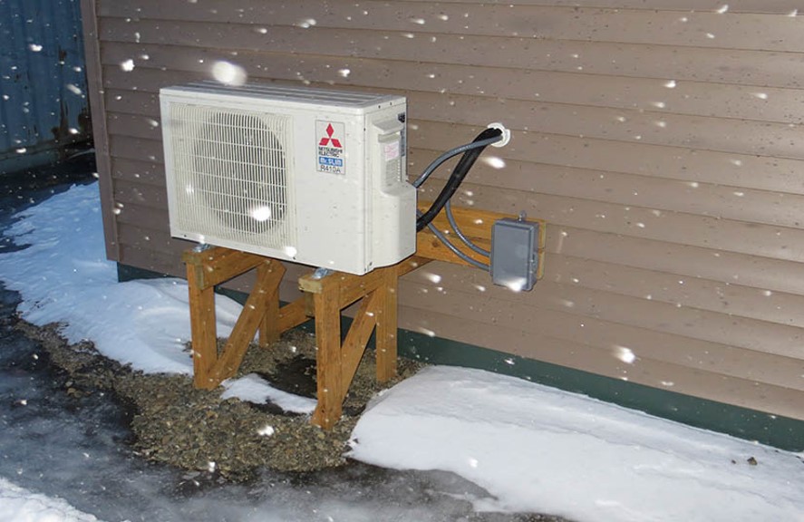
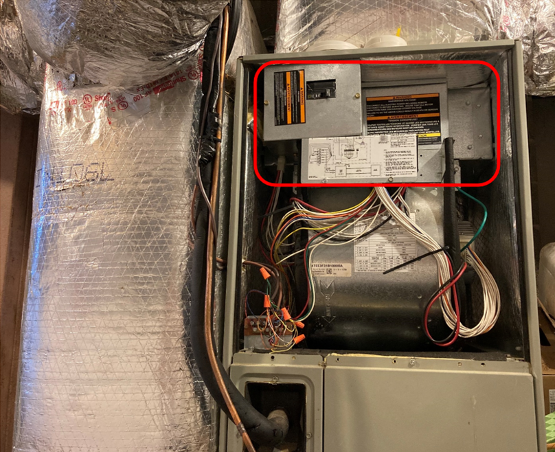
Even in relatively warm climates, heat pumps have traditionally been installed with a backup heat source (auxiliary heat), usually an electric resistance element (Figure 2). This backup heat ensured the home could still be heated at cooler outdoor temperatures (e.g., below 35°F). This electric resistance backup is an inefficient and typically expensive form of heat, which should be minimized in all cases of heat pump installations.
Source
Until recently, natural gas, fuel oil, and other combustion heating systems have been preferred over heat pumps in cold climates because they do not lose heating capacity when the outside temperature drops. However, developments in heat pump technology allow some models to operate efficiently and with near-full capacity at very cold temperatures. These “cold climate air-source heat pumps” (ccASHPs) are now a viable heating source in any U.S climate zone. ccASHPs are designed specifically to maintain the use of the heat pump technology even at cold temperatures, minimizing or avoiding the use of expensive auxiliary heat.
Cold Climate Heat Pump Specifications
Specifications and criteria for ccASHPs have been developed by ENERGY STAR to define whether a model can be considered a certified cold climate heat pump within their program. These criteria include the following:
• Heating Seasonal Performance Factor 2 (HSPF2): ≥ 8.5 for ductless systems, ≥ 8.1 for ducted systems
• Coefficient of Performance (COP) at 5°F ≥ 1.75 (when operating at maximum capacity)
• Heating capacity at 5°F ≥ 70% of rated capacity at 47°F
• Seasonal Energy Efficiency Ratio 2 (SEER2) ≥ 15.2
Similar specifications have been created by the Northeast Energy Efficiency Partnerships (NEEP), DOE Cold Climate Heat Pump Challenge, the Northwest Energy Efficiency Alliance (NEEA), and the Consortium for Energy Efficiency (CEE). These specifications give consumers and contractors confidence that a particular make and model is appropriate for a cold-climate application. They also allow manufacturers to market their equipment as meeting the requirements of a particular program such as ENERGY STAR.
Databases of Cold Climate Heat Pumps
NEEP has created the Cold Climate Air Source Heat Pump List, a free, open-access listing of heat pump models that meet the minimum criteria in the Air-Source Heat Pump Specification 4.0. This list contains valuable extended-performance data for each model listed. The NEEP site also has a tool to aid designers in sizing a heat pump to focus on heating rather than cooling (Figure 3).
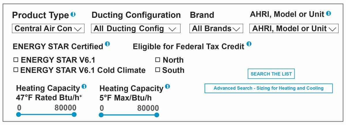
Additionally, ENERGY STAR maintains the ENERGY STAR Certified Heat Pumps database, a list of products that meet ENERGY STAR efficiency criteria. This list contains a checkbox filter feature allowing users to filter out non-ccASHPs as well as search for specific brands, capacities, efficiency levels, and tax credit eligibility.
Why Sizing Cold Climate Heat Pumps is Different
Heat pumps, unlike furnaces, air-conditioners, boilers, or baseboard heaters, provide both heating and cooling from the same piece of equipment. This presents a unique challenge to the HVAC designer and installer: should the heat pump be sized to meet the heating needs or the cooling needs of the home? Can it be sized to efficiently meet both?
The heating capacity of a traditional single-stage heat pump is related to its cooling capacity: the higher the cooling capacity, the higher the heating capacity. Because of this, it can be very difficult to match a traditional heat pump’s size to both the heating load and the cooling load of a house.
Oversizing and Undersizing
In any case, usually either the heating or the cooling capacity of a traditional heat pump must be oversized or undersized. The following considerations must be made when under- or oversizing a system for heating or cooling:
- Oversized cooling capacity: The system will cycle on and off more frequently when cooling, causing wear and tear and uneven comfort. It will also not provide good humidity control.
- Oversized heating capacity: The system will cycle on and off more frequently when heating, causing wear and tear and uneven comfort.
- Undersized cooling capacity: The system will not be able to keep the house cool enough during the hottest times, but it will usually dehumidify more effectively.
- Undersized heating capacity: The system will not be able to keep the house warm enough during the coldest times. The auxiliary or backup heat will make up the difference, but at a much lower efficiency.
In most areas of the United States, right-sizing a heat pump for cooling will result in an undersized heating capacity. Conversely, right-sizing for heating will usually result in an oversized cooling capacity. This is particularly true in the cooler regions.
Consider a home in a climate zone 4, a moderate climate zone. The home may have a heating load that is about equal to its cooling load. One might expect that if the heat pump is sized to meet the cooling load, it could also meet the heating load. However, this is not the case because the unit’s heating capacity drops below its rated capacity once the outdoor temperature drops below the mid-40’s or so. By the time the outdoor temperature is down into the teens, the heat pump can only provide a fraction of its rated capacity. The unit will be undersized for heating. In colder climate zones (5, 6, 7, 8), the situation is more exaggerated.
Why Traditional Sizing Practices Shouldn’t be Used for Cold Climate Heat Pumps
Traditionally, best practice has been to right-size the heat pump for cooling. Often this meant that the heating capacity was undersized, but the system would make up for any lack of heating capacity with auxiliary heat. A system sized this way will provide enough cooling during design conditions, should properly dehumidify, and will not cycle on and off too frequently. Meanwhile comfort is not compromised on the heating side due to the auxiliary heat. This approach works well in the warmer regions of the United States because the heating loads are not high, and the use of auxiliary heat is not excessive.
However, in colder climates this approach would be problematic. Right-sizing a heat pump for cooling means the heat pump will be sized smaller in colder climates. This will result in more significantly undersized heating capacities. For these climates, heating demands will be higher and selected heat pump heating capacities will be lower. Consequently, traditional heat pumps and traditional sizing methods may no longer apply to such scenarios because much of the heat for the home will come from the lower efficiency auxiliary heat source rather than from the heat pump compressor itself.
Variable-Capacity Heat Pump Sizing
Variable-capacity technology allows designers to veer from traditional sizing methods. These heat pumps can modulate their output and operate at lower capacities than their rated maximum capacity. Turndown ratio is a term used to describe how much a unit can modulate its capacity. Specifically, turndown ratio equals the unit’s maximum capacity divided by its minimum capacity. If a unit can modulate to a very low capacity compared to its maximum capacity, it is said to have a high turndown ratio. This means that if a system is oversized it can still operate at a lower capacity without needing to cycle on and off as frequently, decreasing system wear in increasing efficiency.
Variable-capacity heat pump technology allows heat pumps to be right-sized for heating and oversized for cooling with less concern about comfort and efficiency. This makes heat pumps in colder climates much more attractive. Note that not all variable-capacity heat pumps are ccASHPs, but all ccASHPs are variable-capacity heat pumps.
Cold Climate Heat Pump Performance
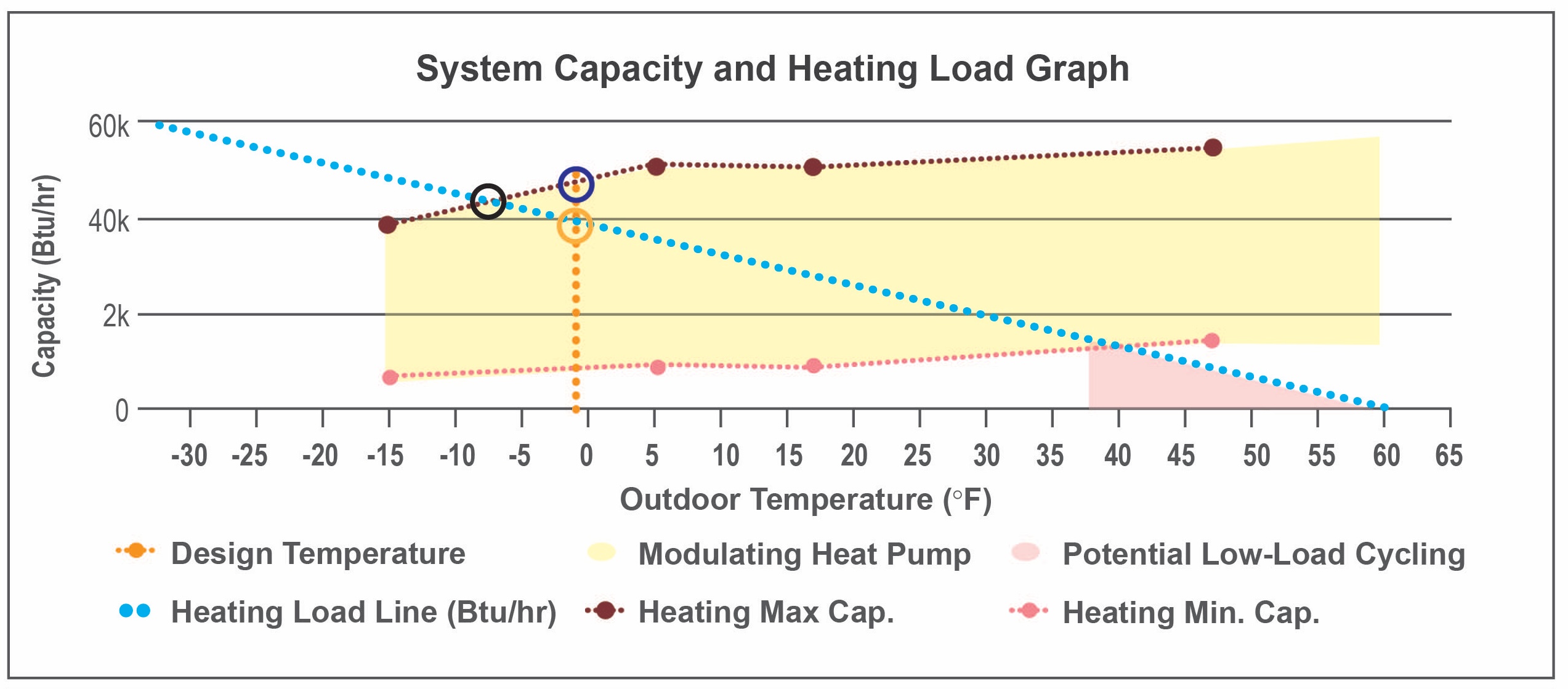
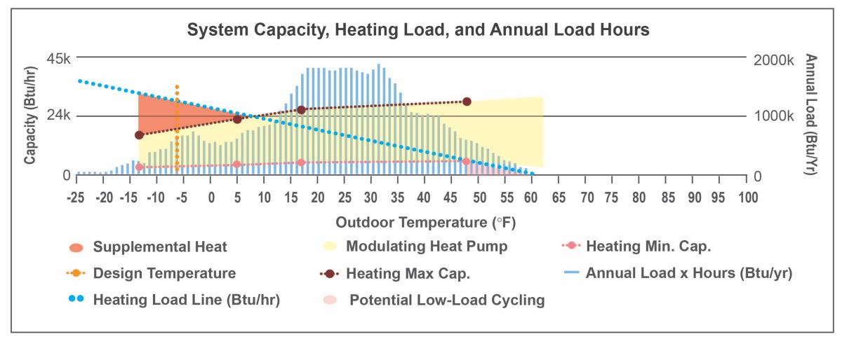
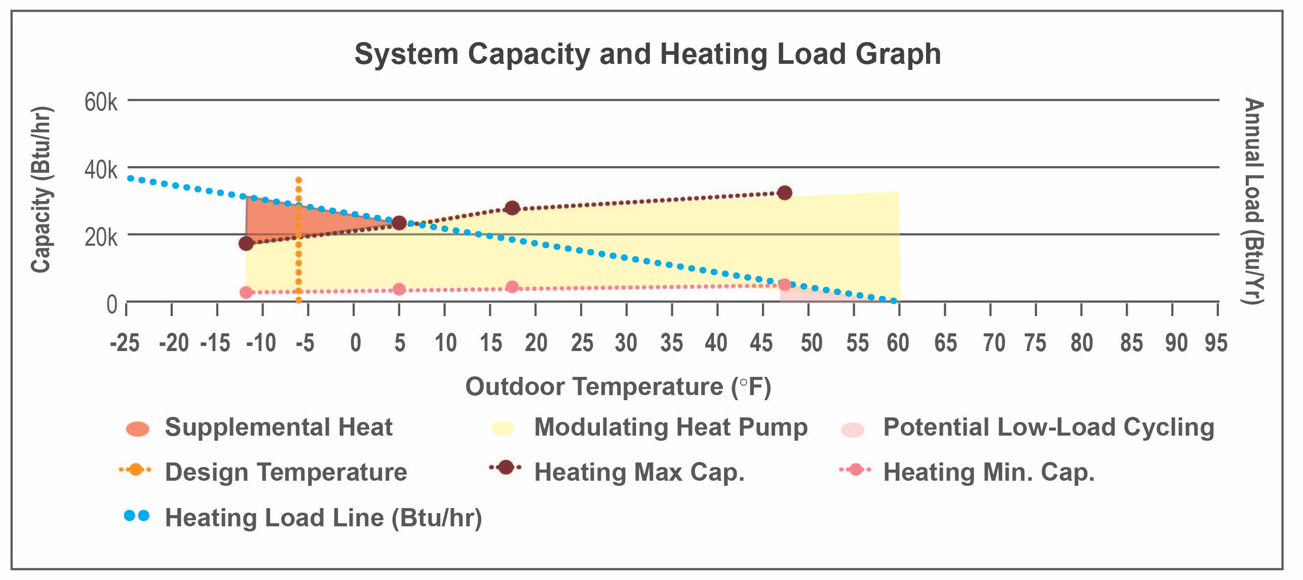
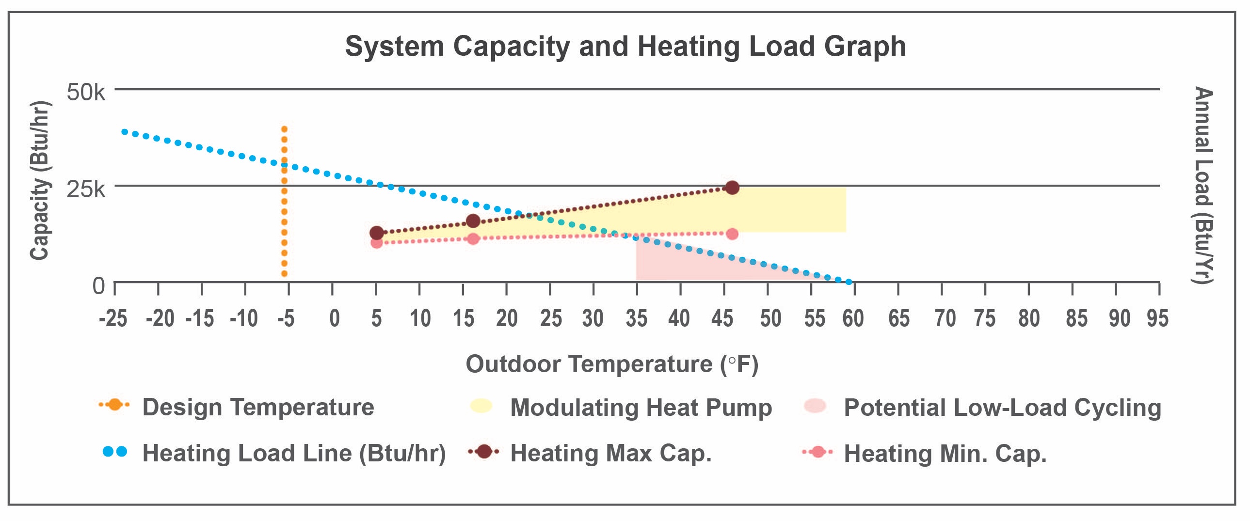
Figure 4 illustrates the key aspects of ccASHP performance. The plot was generated through NEEP’s Cold Climate Air-Source Heat Pump List, then enhanced slightly to highlight key information. The information gained through this type of plot is of great value in sizing and selecting equipment for a specific home.
Source
Database compiling extended capacity data for numerous cold climate heat pump manufacturers and models.
- Design outdoor temperature. The vertical gold line indicates the design outdoor temperature for the location of the house. This line depends only on the weather data for that location; it is not affected by the characteristics of the house or the characteristics of the heat pump.
- Maximum heating capacity. The mostly horizontal dark red line in the upper area of the plot indicates the maximum capacity of the heat pump at different outdoor air temperatures. This is obtained from the equipment manufacturer’s extended performance tables.
- Minimum heating capacity. The mostly horizontal pink line in the lower area of the plot indicates the minimum capacity of the heat pump at different temperatures. This is obtained from the equipment manufacturer’s extended performance tables.
- Modulating zone. The yellow area between the maximum and minimum heating capacity lines shows the modulating zone of the heat pump. The heat pump can perfectly match the heating needs of the home by continual operation when conditions are within this zone.
- Design heating load. The gold circle indicates the heating load of the home at design conditions. This is the design heating load resulting from Manual J load calculations.
- Heating load line. The sloping blue line is the heating load line for the house. This line indicates how much demand the heat pump will have to meet at various temperatures. It is generated based on ACCA Manual J heating load calculations. This line is created only based on the characteristics of the home; it is not affected by the characteristics of the heat pump. In this example, it is assumed that this home has zero heating load when it is 60°F outside. Note that the heating load line is a simplification of the true heating loads of a home.
- Cycling zone. The pink triangular area to the lower right of the plot indicates the temperatures at which the heat pump will cycle on and off to meet the home’s heating needs. In this zone, the heat pump cannot modulate low enough to run continuously without overheating the space.
- Heat pump capacity at design conditions. The uppermost dark blue circle indicates the capacity of the heat pump at the design outdoor air temperature. This can be compared to the design heating load of the home to understand whether the heat pump will have sufficient capacity to meet all or nearly all of the home’s heating needs (for Figure 4, the answer is yes).
- Balance point temperature. The black circle toward the left of the plot indicates the balance point temperature. When outdoor temperatures are below the balance point, the heat pump cannot fully meet the home’s heating needs without a backup heat source. It is valuable to understand the balance point temperature when intentionally sizing a heat pump to only meet a portion of the home’s needs, such as with dual-fuel systems.
How to Size and Select a Cold Climate Heat Pump
Step 1: Understand Goals and Limitations
This step will require discussion with the homeowner to determine their primary goals for the heat pump (Figure 5). In general, the goal for a heat pump installation will fall into one of four categories:
- The primary purpose of the heat pump is to provide cooling, but it will provide some heat in milder weather.
- The primary purpose of the heat pump is to provide cooling, but the homeowner would like to get as much heating out of the unit as reasonable.
- The primary purpose of the heat pump is to provide most of the heating required, but a backup heating system or significant auxiliary heat is available.
- The heat pump is intended to provide all the heat.
Deciding on a sizing approach mostly depends on which of these options seems to best suit the homeowner.
It is also important to determine the homeowner’s motivation for choosing a heat pump rather than a furnace, boiler, or other heating equipment. The motivation may have to do with concerns about climate change, rising fuel costs, indoor air quality, or improved comfort. Homeowner motivations will help narrow down the system options.

Step 2: Choose a Sizing Approach
Based on the homeowner’s goals determined in Step 1, decide which of the following approaches to take when sizing and selecting equipment (NRCan 2020):
- The homeowner is primarily interested in the heat pump for air-conditioning. It may be used to provide some heat in mild weather but is not the primary heating system: Size to the design cooling load. A ccASHP is not necessary. A standard variable-capacity unit can be used, or even a traditional single-stage unit. However, choosing a ccASHP may trigger federal or other incentive programs.
- The primary purpose of the heat pump is to provide cooling, but the homeowner would like to get as much heating out of the unit as reasonable: Select a variable capacity or multi-stage unit and size the unit such that the mid- or low-end of its cooling capacity range will meet the design cooling load. The unit may technically be oversized for cooling, but the modulating or staged capacity will mitigate oversizing issues. This approach allows a larger unit with more heating capacity to be selected.
- The primary purpose of the heat pump is to provide heat, but a backup heating system or significant auxiliary heat is available, or the system is a dual fuel system. In this case the heat pump is designed to provide most, but not all, of the heat. Select a ccASHP and size the heat pump such that it is somewhat undersized for heating. One approach to this undersizing is to size the heat pump to meet a certain percentage of the design heating load (for example 80%). Another approach is to target a specific balance point temperature which is warmer than the design heating temperature. Select a unit with a minimum cooling capacity that is lower than or equal to the design cooling load.
- The heat pump is intended to provide all or nearly all the heat. Size to meet the design heating load at the location’s design heating temperature. Incorporating a safety factor to slightly oversize the unit for heating is acceptable, especially if the goal is to minimize or eliminate a backup heat source. Use a ccASHP. Select a unit with a minimum cooling capacity that is lower than or equal to the design cooling load.
Table 1 summarizes these four sizing approaches. Options 1, 2, and 3 will require an auxiliary source of heat during the colder parts of the winter.
Table 1. There are 4 primary approaches to sizing a heat pump in a cold climate; the approaches move progressively from simply meeting the cooling load to meeting 100% of the heating load (Source: Courtesy of PNNL).
| Cold Climate Sizing Approach | Heating Capacity | Cooling Capacity | Heat Pump Type | |
| 1 | Size for cooling | Significantly undersized | Right-sized | Single-stage will work |
| 2 | Size for cooling, but maximize available heating | Undersized | Oversized at max capacity, but right-sized within capacity range | Multi-stage or variable capacity, possibly ccASHP |
| 3 | Size to meet most of the heating load | Somewhat undersized | Oversized at max capacity. Try to right-size within capacity range | ccASHP with wide enough turn-down ratio for proper cooling |
| 4 | Size to meet all the heating load | Right-sized | Oversized at max capacity. Try to right-size within capacity range | ccASHP with wide enough turn-down ratio for proper cooling |
The sizing approach used will shift the balance point temperature of the system. Approach 1 will have the warmest balance point, and Approach 4 will have the coldest. The balance point temperature dictates when the home can take full advantage of the heat pump and when it must use an alternate heating source. Approaches 1, 2, and 3 will require an auxiliary source of heat during the colder parts of the winter.
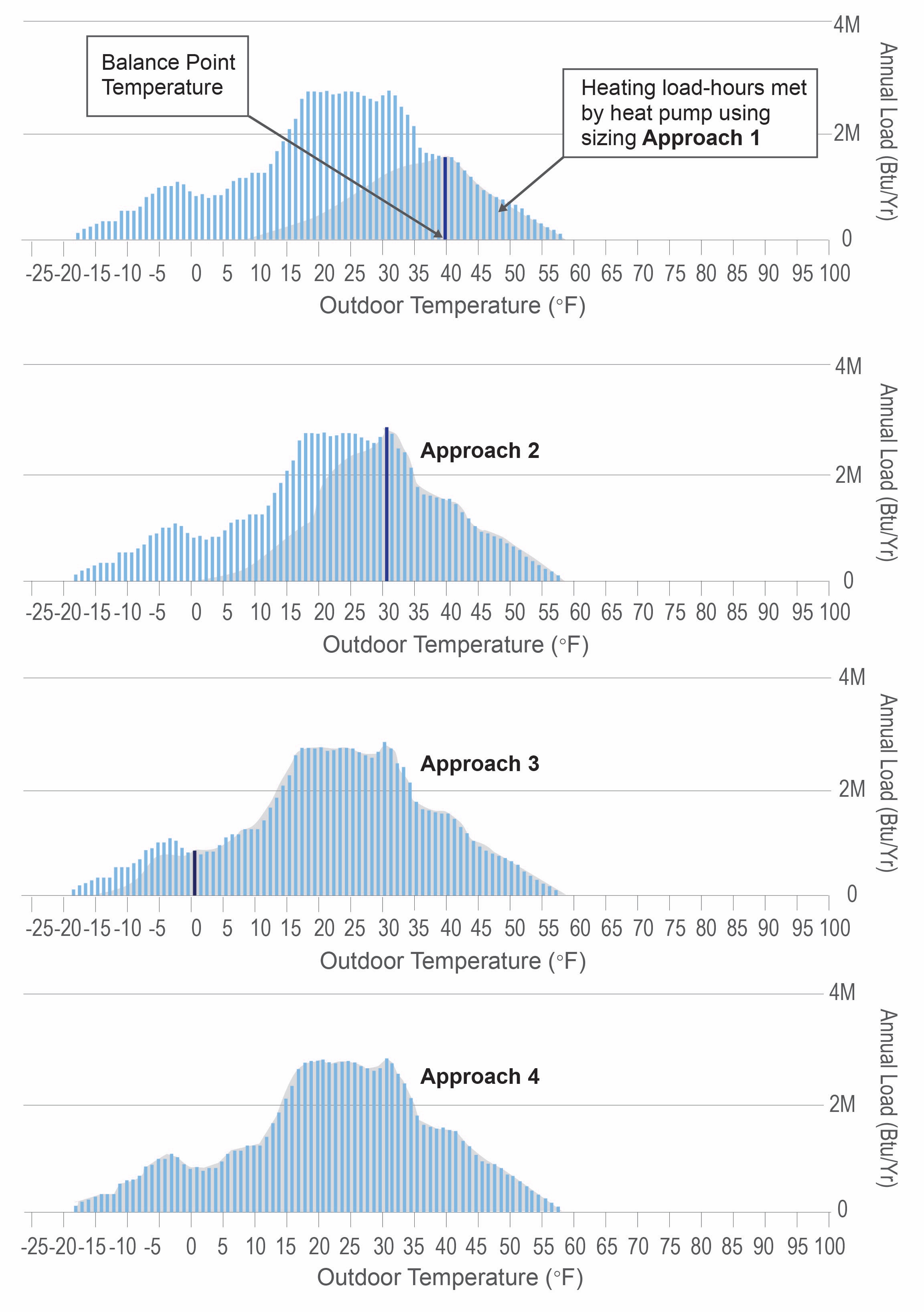
Figure 6 illustrates a hypothetical example of how much of the annual heating load a heat pump could meet using each sizing approach. Annual Load Hours (vertical blue bars) indicate the total amount of heat the home needs at different temperatures over the course of a year. The gray portion of the chart shows how much of the heating could be provided by the heat pump. Annual Load Hours are obtained by multiplying the number of hours/year the location is at each outdoor air temperature by the home’s heating load at that temperature. Although the home’s heating load at very cold temperatures is very high, the location doesn’t get that cold very often, so the Annual Load Hours at these temperatures is small because the number of hours is small. Vice versa at mild temperatures: the number of hours may be large, but the heating load is very small, making the Annual Load Hours small.
This example in Figure 6 uses weather data for Minneapolis, MN. In this example, Approach 1 has a balance point temperature of 40°F, Approach 2 has 30°F, Approach 3 has 0°F, and Approach 4 has -15°F. Below these temperatures, the heat pump could meet some, but not all, of the home’s heating load. Note that the balance point temperature for Approach 4 is colder than the heating design temperature for Minneapolis, which ensures the heat pump will meet the full heating needs of the home without relying on auxiliary heat during design conditions (ASHRAE 2021).
Source
Database compiling extended capacity data for numerous cold climate heat pump manufacturers and models.
Figure 6 also provides insight into the effect of the chosen backup heat strategy. In the case of typical electric resistance auxiliary heat, the heat pump can continue to contribute simultaneous to the auxiliary heat. In this case the unshaded blue portion of the plot represents the part of the home’s heating load that would need to be met by the auxiliary heat. If the backup heat uses a switchover strategy where the heat pump does not operate alongside the backup heat, then all blue and gray sections of the plot to the left of the vertical balance point temperature line would need to be met by the backup heating source. This is often the scenario with natural gas dual fuel systems.
Step 3: Choose a System Configuration
How to configure the system will depend on the characteristics of the home as well as the goals and motivations discussed with the homeowner in Step 1. The sizing approach in Step 2 can also inform the decision made here, though the two steps can be switched. For an existing home, the existing ductwork (or lack thereof) can be a significant factor in which system configuration will make the most sense. Evaluating an existing air distribution system is critical before deciding to reuse it with a heat pump, especially in cold climates.
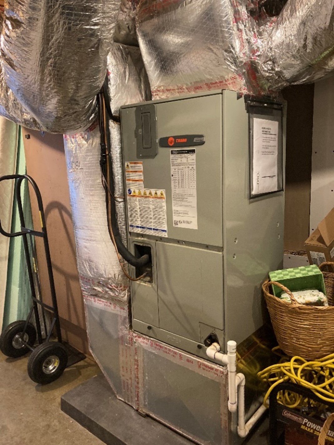
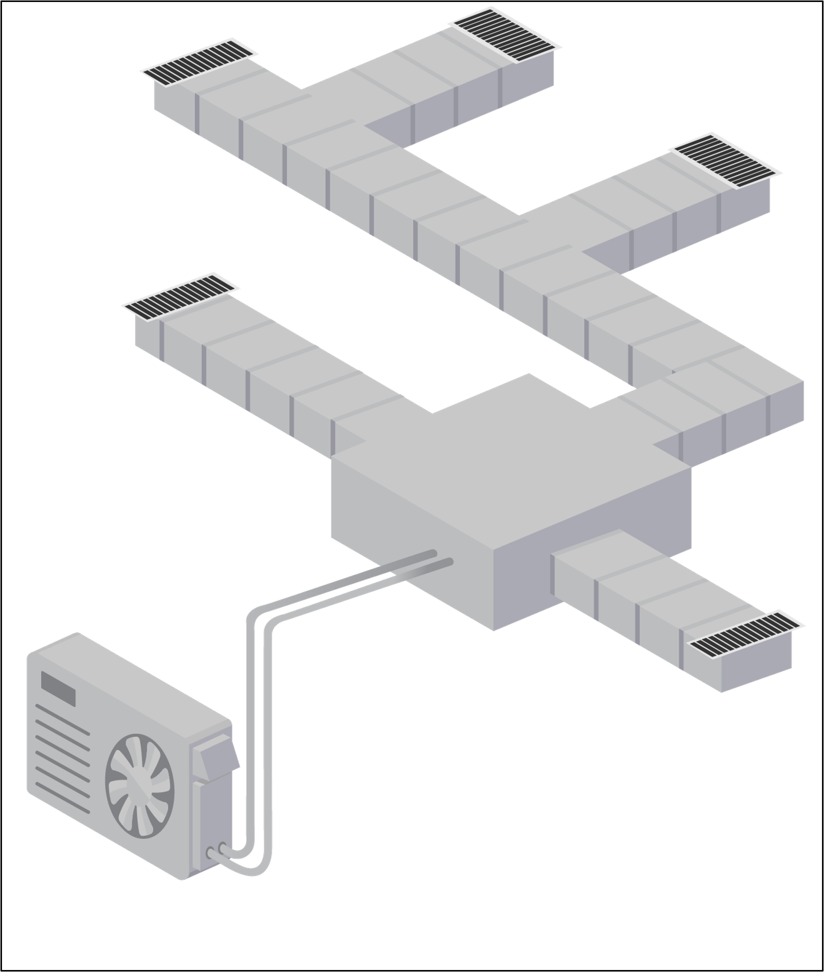
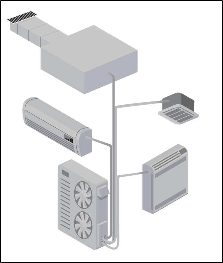
Options for system configuration include centrally ducted, single-zone mini-split, multi-split (a split system with multiple indoor units and one outdoor unit), and combination ducted/ductless systems. Illustrations of various system types are provided in Figures 7 – 10.
Source
Source
Source
Source
Step 4: Perform Heating and Cooling Load Calculations
Regardless of whether the focus of the system is on heating or on cooling, heating and cooling load calculations should both be performed to allow selection of equipment that can best serve both purposes. While numerous rules of thumb and simplified calculators exist, ACCA Manual J should be used to obtain reliable results. ACCA-approved software tools are available to simplify the process.
When performing load calculations, it is important to enter accurate data about the home’s envelope air leakage rate and insulation levels. A blower door test is the most accurate way to determine a home’s envelope air leakage rate. Additional upsizing or rounding up is not needed when following the Manual J process and can lead to oversizing. Using rules of thumb will also typically lead to the selection of an oversized unit to meet an unrealistic heating load. This will make it more difficult for the designer to select a heat pump with a sufficiently low minimum cooling capacity for the actual cooling load.
If the new heat pump is intended to only serve a portion of the house, then the heating and cooling loads should be calculated to include only that portion of the house. As a best practice, room by room load calculations are recommended.
Step 5: Size Equipment
The results of the heating and cooling load calculations will be used to size and select the specific heat pump equipment. Select a target heating and/or cooling capacity for the new heat pump based on the sizing approach chosen in Step 2. For example, if you chose Approach 1, you would use 100% of the cooling load as your target cooling capacity for the unit. For Approach 2, you would allow the unit to have a capacity higher than 100% of the cooling load. For Approach 3 you might choose, for example, 80% of the heating load as your target capacity (but also keeping the cooling load in mind). For Approach 4, you would choose 100% of the heating load and the cooling load as your targets.
ACCA Manual S provides a sound method for sizing heat pumps, but until recently the sizing focus has been on the cooling load, not the heating load. In 2023 ACCA released the 3rd Edition of Manual S for Residential Equipment Selection, which expanded upon previous versions to allow for heating-focused sizing with ccASHPs. The 2nd edition of Manual S is appropriate when sizing the heat pump with focus on the cooling load, but when targeting the heating load, the 3rd edition should be used.
Step 6: Select Equipment
6a. Obtain Extended Performance Data
Equipment should not be selected based on nameplate capacity. Instead, the capacity at design conditions must be determined. Manufacturers’ extended performance data should be used to determine heating and cooling capacities at the design temperatures for the home’s location. The primary information needed is the maximum and minimum heating output (capacity) of the unit at various outdoor temperatures and the maximum and minimum cooling output at various outdoor temperatures. This data will typically be shown in units of BTUs/hr (also shown as BTU/h or BTUH), kBTU/hr, or tons. The data can be found on manufacturer websites, but the capacity at colder design temperatures may not be listed. For ccASHPs, the Cold Climate Air Source Heat Pump (ccASHP) List by NEEP provides a single source for capacity tables and charts for multiple ccASHP manufacturers, though the information provided may not be as comprehensive as the manufacturers’ tables.
See Table 2 as an example of the data provided on the NEEP ccASHP List. This table indicates, for example, that when the outdoor temperature is 5°F, the unit can produce a maximum of 48,000 BTU/hr of heat and can modulate or stage down to a minimum of 7,133 BTU/hr.
Table 2. This table from the NEEP Cold Climate Air Source Heat Pump List shows extended performance data for a specific heat pump model (Source: NEEP 2022).
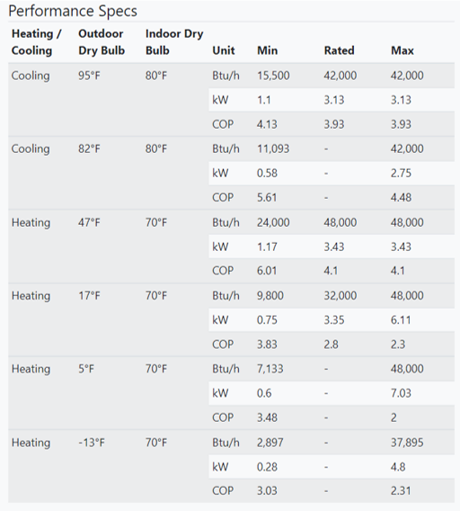
If a unit’s capacity at a specific design outdoor temperature is not specified, an estimate of the output at a given temperature can be estimated from the available data. For example, the equipment capacity for a design temperature of 0°F can be estimated using the listed capacities at 5°F and -13°F. Table 2 shows us that the maximum capacity at 0°F for this heat pump will be between 37,895 BTU/hr and 48,000 BTU/hr. A method known as linear interpolation can be used to obtain a more precise estimate. See the Success tab for an explanation of how to use linear interpolation.
Extended performance data obtained directly from the manufacturer can include heating and cooling outputs at more outdoor air temperatures than required by AHRI or shown in the NEEP ccASHP List. This data is very useful for more closely matching heating loads, especially at very low temperatures.
Manufacturer literature such as specification sheets or proprietary equipment tools often contain this extended performance data in 5°F increments.
6b. Compare Heating Load to Heating Performance
Once performance data are obtained, they should be compared to the heating needs of the home. A primary challenge in selecting a cold climate heat pump is to identify a unit with a high enough maximum heating capacity to meet the client’s needs but low enough minimum heating and cooling capacities to reduce short-cycling. Short-cycling lowers efficiency, and in cooling mode can cause issues with humidity. Short-cycling can cause humidity issues because short runtimes do not allow enough time for moisture to gather on the coil in sufficient quantity to begin dripping to the condensate pan where it can be collected and drained or pumped out of the home.
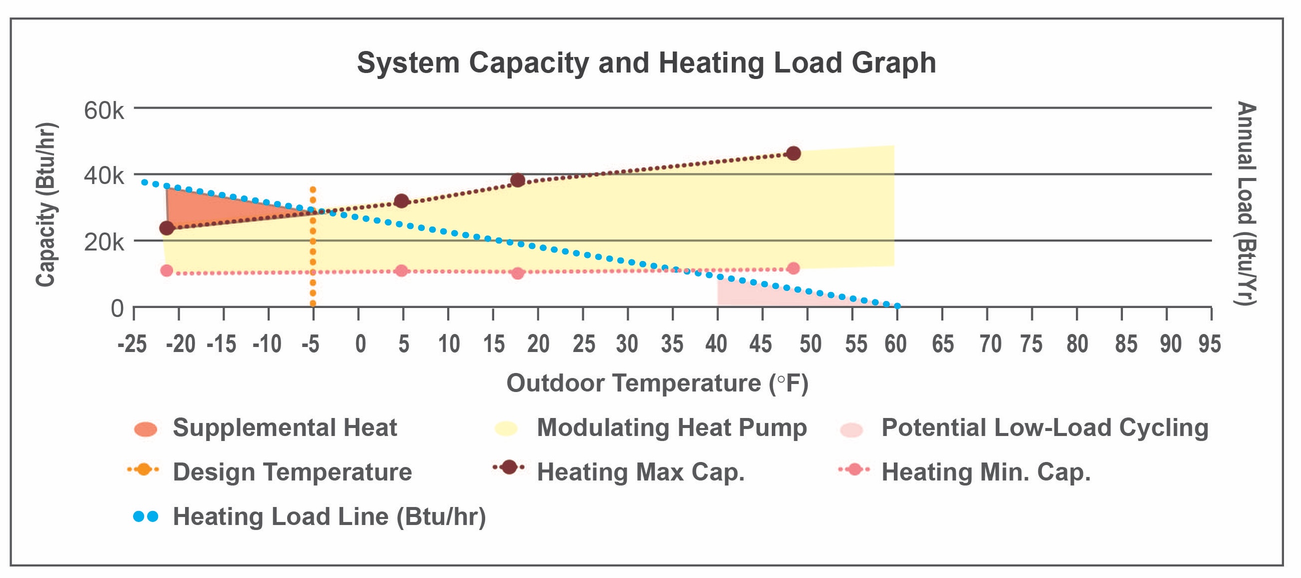
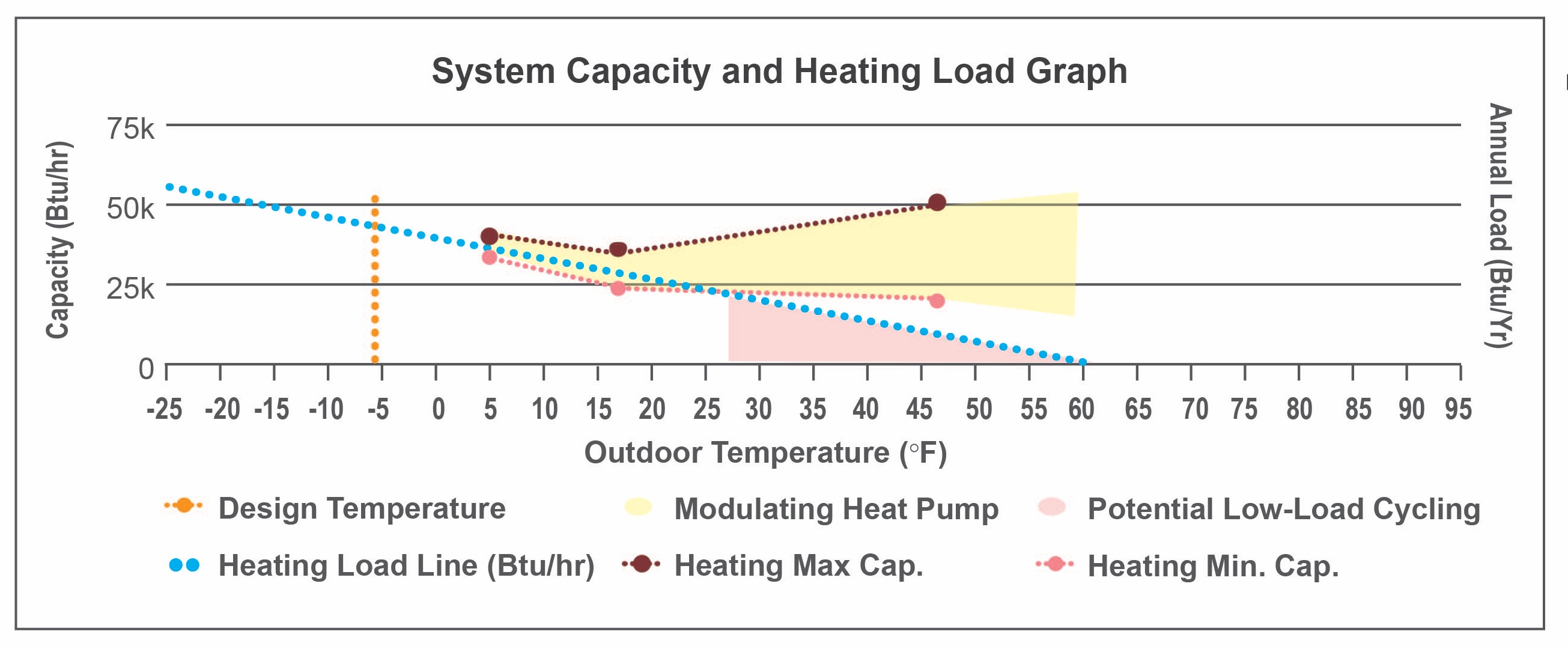
Figure 11 shows a plot of the data presented above in Table 2. Note that this is for a specific heat pump model. The plot also includes the heating load line for a home with a design outdoor temperature of -7°F and a design heating load of 41,000 BTU/hr. See the section on “Cold Climate Heat Pump Performance” above for a full description of this type of plot.
Source
Database compiling extended capacity data for numerous cold climate heat pump manufacturers and models.
The following key information can be gained quickly by viewing this plot:
- The heat pump capacity at the design heating temperature is greater than the design heating load. This indicates that the heat pump should be able to meet all or nearly all of the heating needs of the home without auxiliary heat.
- The heat pump will efficiently modulate much of the time when the outdoor temperature is lower than about 32°F. Above 32°F the unit will cycle on and off more, reducing efficiency and increasing equipment wear.
The “Advanced Search – Sizing for Heating and Cooling” feature on NEEP’s Cold Climate Air Source Heat Pump List provides additional valuable information in both table and graph format, including:
- Balance Point Temperature: Indicates the lowest outdoor temperature at which the unit can provide all the home’s heating needs.
- Design Load Served: Indicates how much of the home’s heating load can be met by the heat pump at the winter design temperature.
- % Annual Load Served: Indicates how much of a home’s annual heating BTUs can be provided by the heat pump.
- % Annual Load Modulating: Indicates what percentage of operating time the unit is operating in the modulating zone (avoiding cycling).
- Minimum Capacity Threshold: Indicates the temperature above which the unit will cycle on and off rather than modulating.
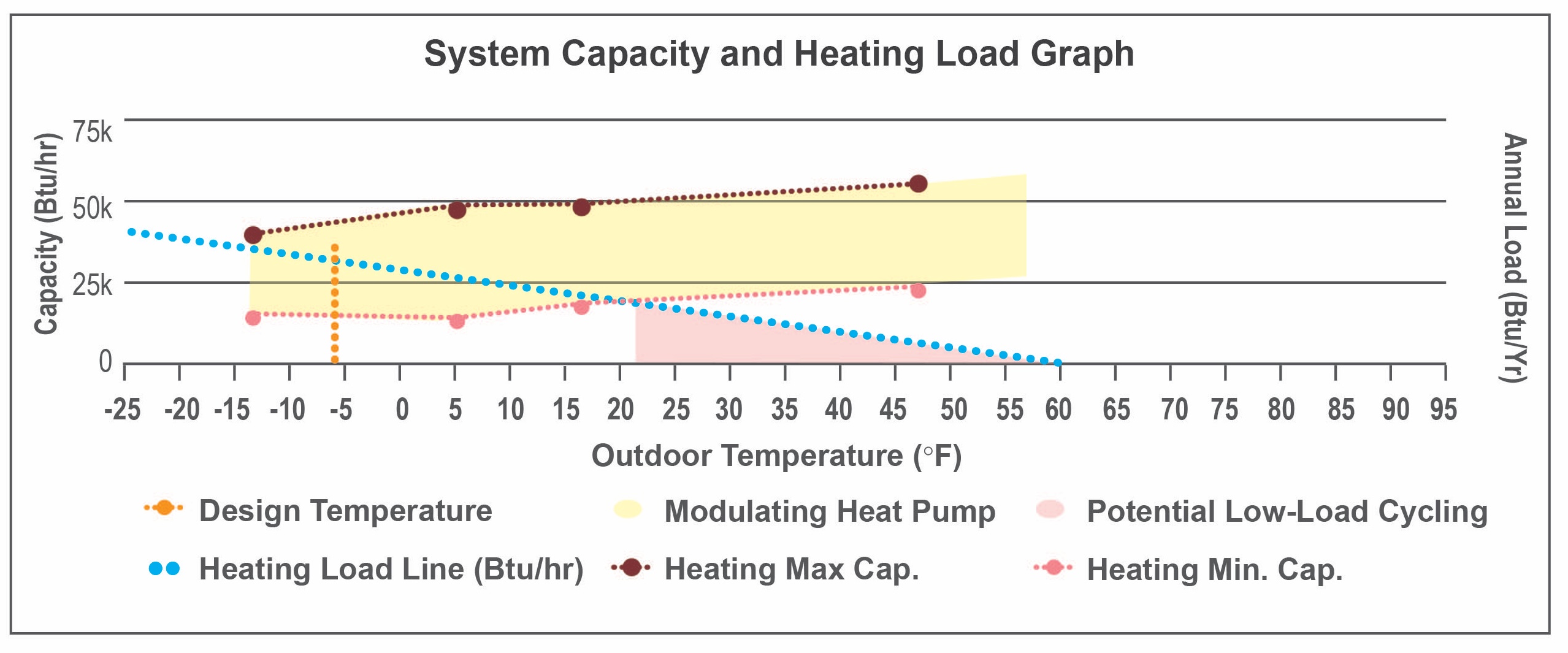
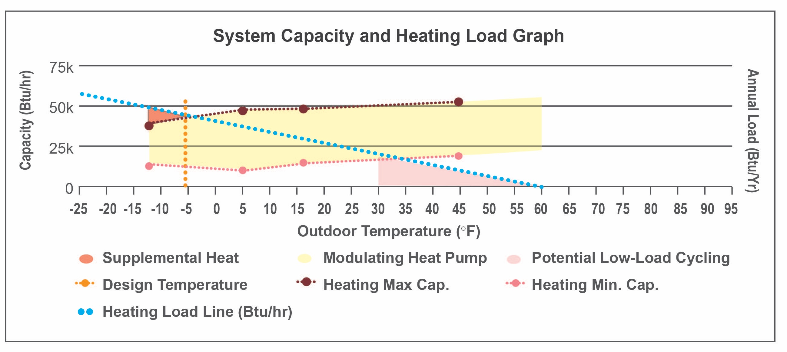
Figure 12 shows this information in graphical form. This graph shows the same types of information as were shown in Figure 11, but for a different heat pump and a different home. Figure 12 also shows the Annual Load Hours (vertical blue bars). An explanation of Annual Load Hours is given above, in the discussion for Figure 6.
Annual Load Hours gives an excellent indication of how much of a home’s total heating energy needs can be met by the heat pump versus a backup heat source. In the example of Figure 12, the balance point temperature is about 7°F. Most of the home’s heating load hours are above this temperature, indicating that the majority of this home’s annual heating needs will be met by this particular heat pump. The following key information can be gained quickly by viewing this plot:
- The heat pump cannot meet all of the home’s heating needs; below about 7°F a backup heat source is needed.
- At design conditions, the heat pump can meet about 2/3 of the home’s design heating load.
- This heat pump will meet most of the home’s total annual heating needs.
- This heat pump will modulate for most of the time it is operating.
- The heat pump will cycle more when the temperature is above 48°F, which represents a very small portion of the home’s annual heating load hours.
- This heat pump appears to be a good match for the home if using sizing Approach 3.
It can be challenging to match a single heat pump model to a particular home, especially if the home experiences extreme temperatures along with many hours of milder weather. In such cases a good strategy may be to incorporate multiple systems in the design. For instance, one system could be optimized to reduce cycling in milder weather while another could be optimized to provide efficient heating in very cold weather.
6d. Compare Cooling Load to Cooling Performance
It is also important to look at the cooling performance of a heat pump compared to the cooling needs of the house. Data from NEEP’s Cold Climate Air Source Heat Pump List is highly valuable for this comparison as well. First, the maximum cooling capacity should be compared to the design cooling load. If the maximum cooling capacity is higher than the design cooling load, then the unit can provide adequate cooling.
Next, the minimum cooling capacity should be compared to the design cooling load (or better yet, the cooling load line on a plot). If the minimum cooling capacity is lower than the design cooling load, the unit will be able to operate without cycling at least some of the time. In general, the lower the minimum cooling capacity is compared to the design cooling load, the more efficiently the unit will run and the better it will dehumidify. If the minimum cooling capacity is higher than the design cooling load, the unit will short-cycle excessively.
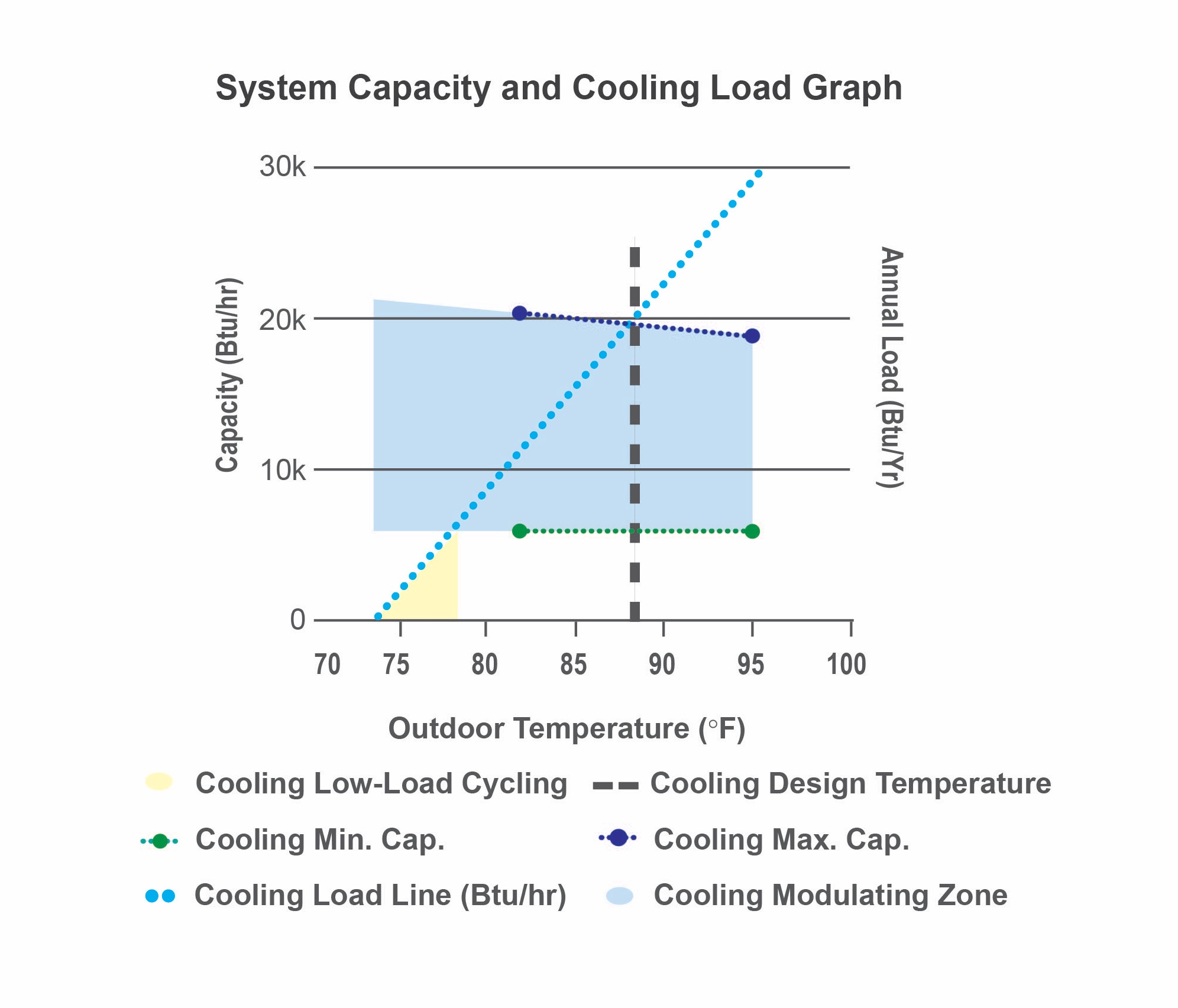
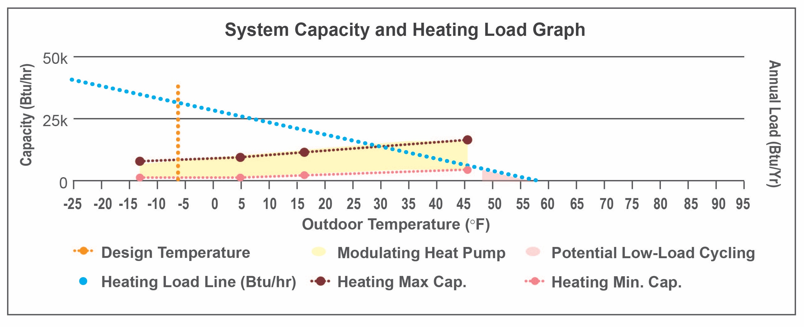
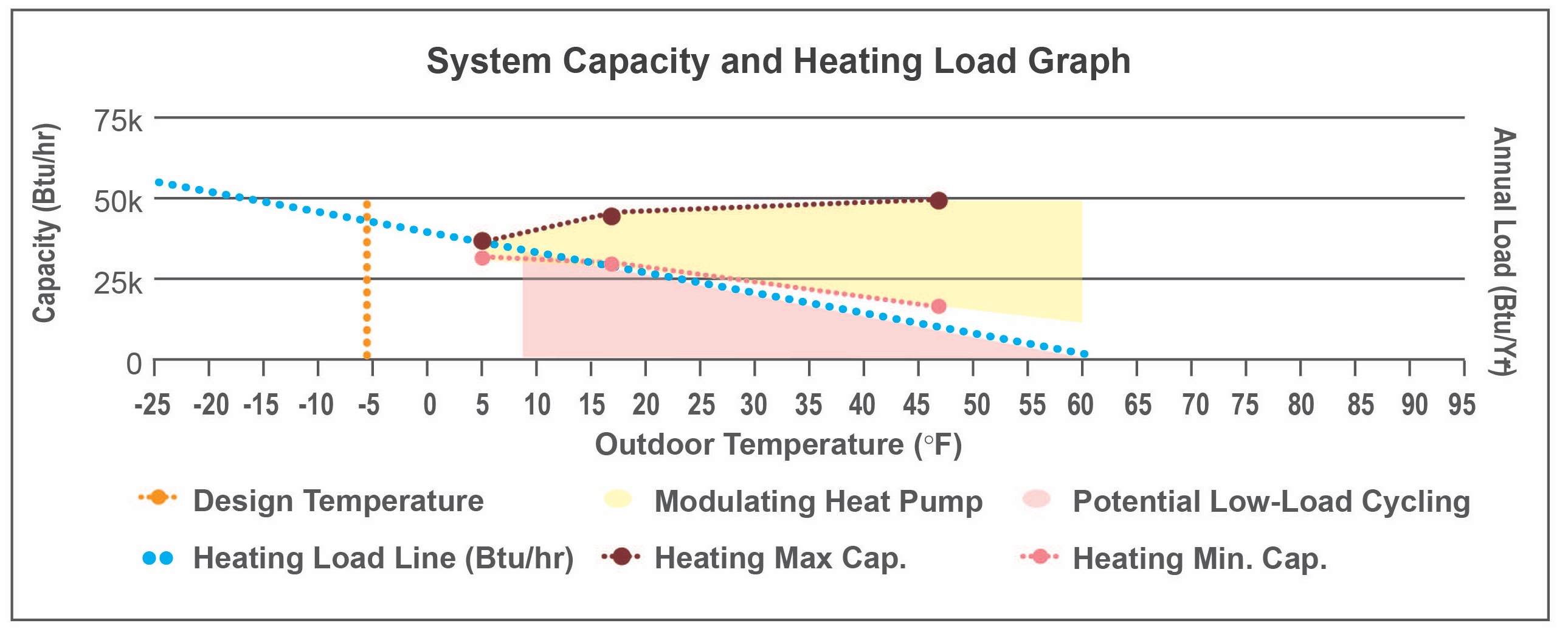
Figure 13 shows a plot from the NEEP database indicating the maximum and minimum cooling capacity of a unit overlaid with the home’s cooling load line. This plot can be analyzed in a similar manner to Figures 4, 11, and 12 for heating.
Source
Database compiling extended capacity data for numerous cold climate heat pump manufacturers and models.
The following key information can be gained quickly by viewing this plot:
- The cooling capacity at the design cooling temperature is very close to the design cooling load. This indicates that the heat pump should be able to meet all or nearly all of the cooling needs of the home.
- The heat pump will efficiently modulate in cooling much of the time when the outdoor temperature is higher than about 78°F. Below 78°F the unit will cycle on and off more, reducing efficiency, increasing equipment wear, and reducing humidity control.
6e. Consider Humidity Control
Dehumidification (latent cooling) is another important consideration for homes in humid climates or for tightly built homes where humidity is not properly exhausted. Dehumidification has historically been an important function of traditional heat pumps and air conditioners, particularly in humid climates. Newer variable-capacity heat pumps sized to meet higher heating loads may not provide adequate dehumidification, however. This is due both to equipment design and to sizing. If installing a variable capacity cold-climate heat pump in a humid climate, or if high humidity may be an issue in the home, consider the following information:
- Variable-speed blowers are often required to pair with variable-capacity heat pumps to achieve better dehumidification. Lower airflow speeds lead to more dehumidification.
- Latent cooling capacities are found in extended performance data from manufacturers (this data is not currently available on the NEEP database).
- Sensible Heat Ratio (SHR) is a good indicator of dehumidification performance. A unit with a lower SHR will provide better dehumidification (for example 0.75). SHR is reported by some manufacturers, but not all.
- Some units have a dehumidification mode, or “dry mode.” Manufacturers may provide data on the performance of the dehumidification mode.
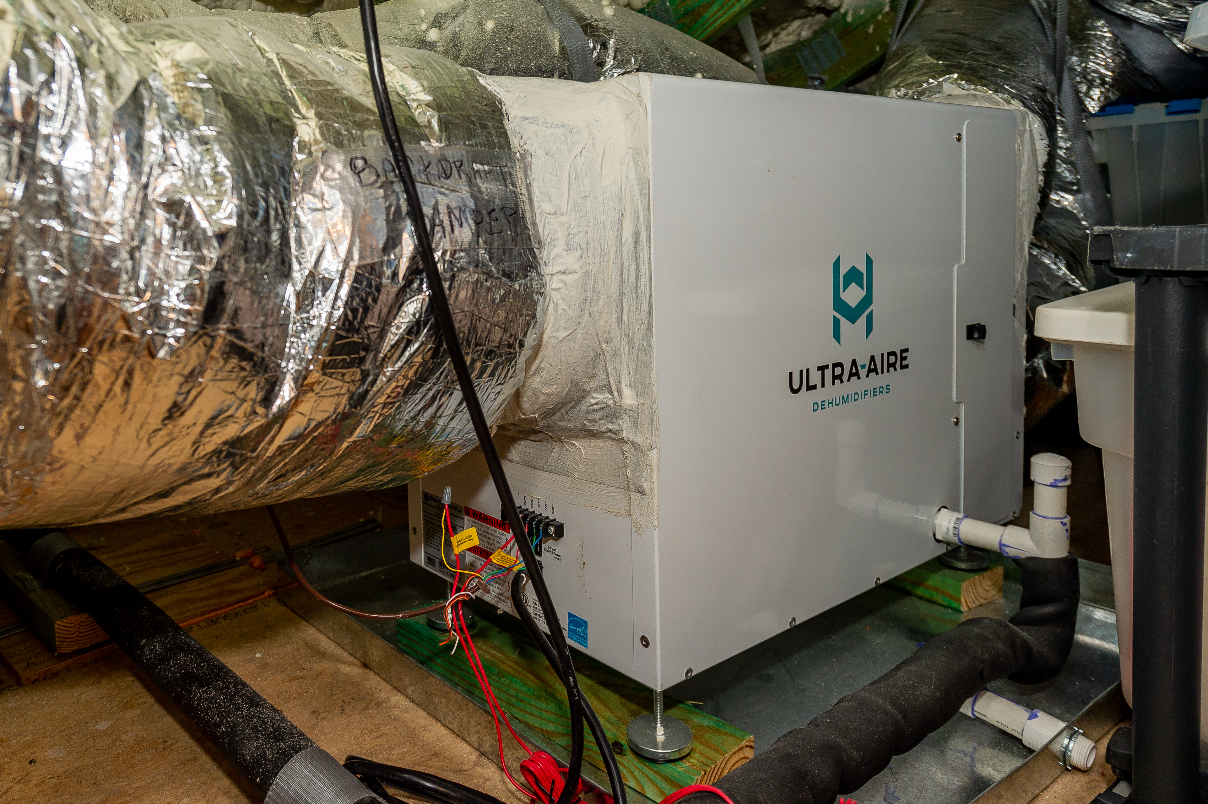
Utilizing a separate whole-house dehumidifier or ventilating dehumidifier may be the most reliable way to provide adequate dehumidification (Figure 14). Whole-house dehumidification allows for the latent capacity of a heat pump unit to be disregarded, meaning that equipment can be sized for large heating loads more easily. See “Whole-House Dehumidification” for more information on dehumidification systems.
Source
6f. Consider Efficiency
The operating efficiency of the selected heat pump will directly affect the energy bills paid by the homeowner and the environmental impact of the unit. HSPF2 is the best easy-to-obtain measure of heating efficiency. With a little more effort, a better metric is COP at outdoor temperatures where the home has the most Annual Load Hours (see Figure 12). For cooling, SEER2 can be used to compare equipment, or COP at outdoor temperatures where the home has the most annual cooling load hours. Another approach is to only consider units that meet the specifications of organizations like NEEP, ENERGY STAR, or the Consortium for Energy Efficiency (CEE).
Process Summary: Sizing and Selecting a Cold Climate Heat Pump
- Understand the goals and limitations of the client.
- Select a sizing approach from the 4 approaches presented above.
- Choose a system configuration (ducted, ductless, or both).
- Perform heating and cooling load calculations (ACCA Manual J).
- Size heat pump based on the approach chosen, utilizing ACCA Manual S, 3rd edition and other methods as appropriate.
- Select a heat pump model:
- Narrow down to equipment within range of meeting the target heating load. (Compare the maximum heating capacity of the equipment to the design heating load of the home.)
- Narrow down further to equipment within range of meeting the design cooling load. (Compare maximum cooling capacity of the equipment to the design cooling load of the home.)
- Narrow down further to equipment with minimum cooling capacity lower than the design cooling load. If none, look for the equipment with the lowest minimum cooling capacity. (Compare minimum cooling capacity at the design cooling temperature to the design cooling load.)
- If not planning to use a separate dehumidification system, narrow down to equipment that has sufficient latent cooling capacity to meet the design latent load. (Compare latent cooling capacity at design conditions to the design latent load).
- Look for equipment that will maximize modulation. (Compare the heating load line of the home to the modulating zone of the equipment. Note the temperature where the unit will cycle vs modulate.
- Finally, select a specific make and model based on additional criteria including efficiency and installed cost. Other factors, including whether the product qualifies for specifications from organizations like NEEP, ENERGY STAR, or the Consortium for Energy Efficiency (CEE), as well as local state or utility incentive programs for purchasing and installing cold climate heat pumps can also factor into equipment choice.
Ensuring Success
Cold Climate Heat Pump Decision Tool
Pacific Northwest National Laboratory has created the Cold Climate Heat Pump Decision Tool to guide contractors and installers through the decision-making process for heat pump (HP) sizing, identifying personalized CCHP recommendations, and applicable tax credits, with a focus on retrofits in cold climates.
Utilizing extended Performance Data
Obtaining a heat pump’s performance data at a home’s design outdoor heating temperature is a vital step in the sizing process when sizing for the heating load. Product data sources may not list this data for the exact design temperature, but may list data for temperatures that are above and below the design temperature. In this case, linear interpolation may be used to estimate the performance of the heat pump at the design temperature. There are numerous online calculators for linear interpolation. Also, the plots obtained from the NEEP database (e.g., Figures 4, 11, and 12 on the Description tab) use linear interpolation to show estimated heating capacities between the reported values, including at the design temperature.
It can be helpful to understand the linear interpolation calculation process. Linear interpolation can be used to determine an unknown value when at least two other points in a linear relationship are known. This means that if two points on a line are known, any point in between can be found.
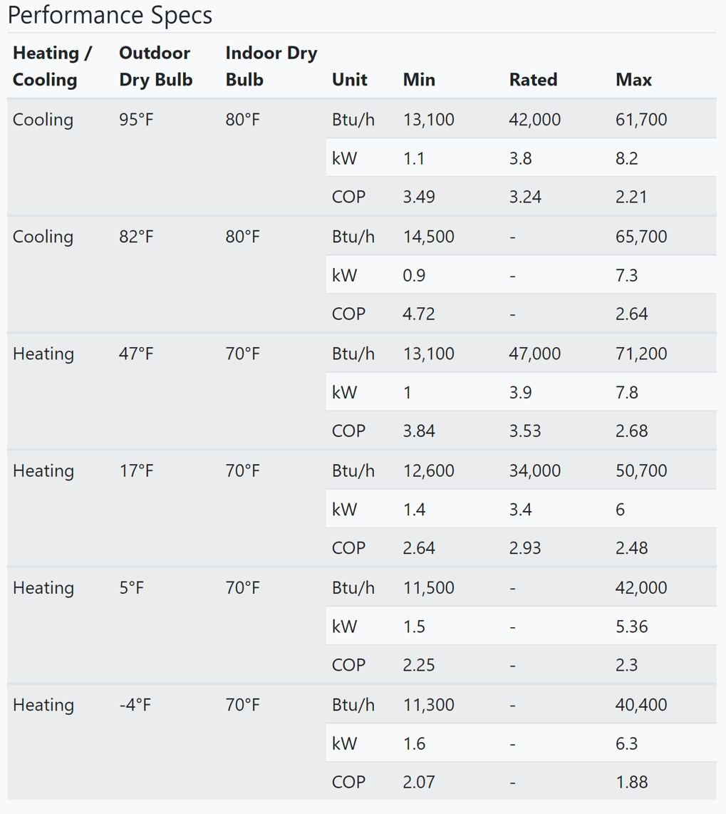
Assume a contractor is considering the heat pump whose extended performance data are shown in Table 1. If the local heating design temperature is 0°F, the contractor cannot get the unit’s capacity directly from the table. However, the contractor knows the capacity at 0°F will be between the capacity at 5°F and the capacity at -4°F, both of which are listed in the table. The contractor will need to use linear interpolation.
Table 1. This table provides the heat pump performance data considered in the example below (Source: NEEP 2024, modified by PNNL).
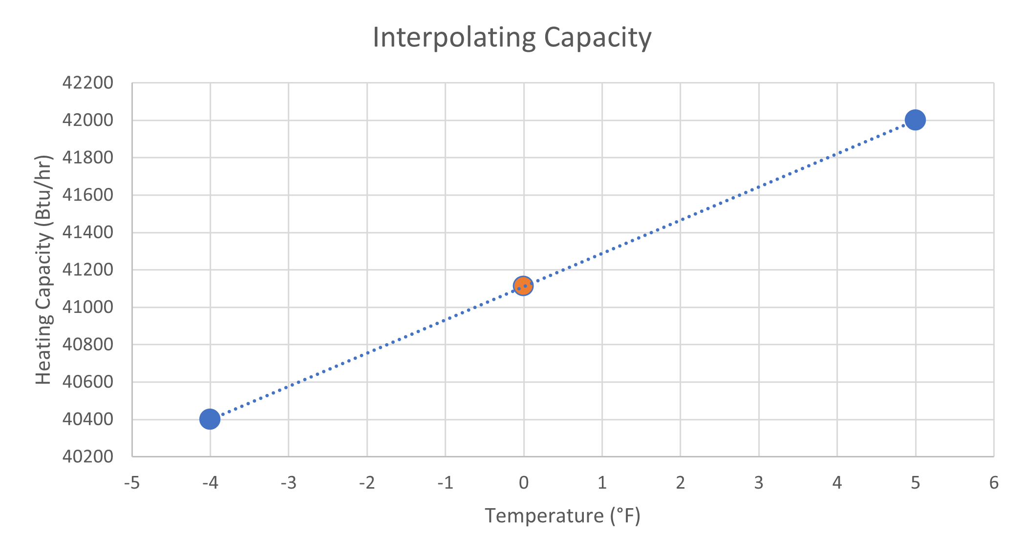
In Figure 1 below, the blue dots represent the known capacities at two known temperatures. By drawing a line between them, the missing value can be found. Simply locate the desired x-coordinate (design temperature) and determine the corresponding y-coordinate (heating capacity) along the line. The orange dot represents this interpolated value of the heating capacity at 0°F. From this graph, we can see that the heating capacity at 0°F is approximately 41,100 Btu/hr.
Source
Webpage providing curriculum with links to presentations and problem sets for teaching an understanding of sizing cold climate heat pumps.
Calculating the answer using a formula will give the exact result. The formula for linear interpolation is shown below. The two known points are (x1, y1) and (x2, y2). The unknown value is y for some value x. Evaluating the formula for a chosen value of x on the line (i.e., in between x1 and x2) will result in y.
y = y1 + (y2 - y1) (x - x1) / (x2 - x1)
Applying this equation to the example above, y represents the unknown heating capacity at the design temperature 0°F. Value x is the design temperature (0°F). Values x1 and x2 are -4°F and 5°F respectively. Values y1 and y2 are the max heating capacities at -4°F and 5°F, as listed in the table. See the completed equation below.
y = 40,400 Btu/hr + (42,000 Btu/hr - 40,400 Btu/hr) (0°F - -4°F) / (5°F - -4°F)
y = 40,400 Btu/hr + (1,600 Btu/hr) (4°F/9°F)
y = 40,400 Btu/hr + 711 Btu/hr
y = 41,111 Btu/hr
The contractor has interpolated the heating capacity at 0°F as 41,111 Btu/hr. Now check to see if this answer matches the value of the orange dot in Figure 1. This kind of calculation can be performed if there is data available for temperatures above and below the design temperature. If the design temperature is not in between the two data points, a similar process called extrapolation would be used. However, this may not hold valid for the case of sizing HVAC equipment and is not recommended.
Region
Choosing a heat pump sizing approach will have different implications in different climates. See Figure 1 for a map of the 2021 IECC climate zones in the United States. In warm climate zones (e.g. zones 1 and 2), the difference between sizing to target 100% cooling (Approach 1) and sizing for 100% heating (Approach 4) may not be very significant. This is because the heating design temperatures in warm climate zones are warm enough that the capacity of a unit sized to meet the cooling load would usually not be very strained in winter conditions.
In climate zones 4 and above, however, the sizing approach should be carefully considered and cold-climate heat pumps should be utilized if a significant portion of the heating load is to be met by the heat pump.

Source
2021 edition of code establishing a baseline for energy efficiency by setting performance standards for the building envelope (defined as the boundary that separates heated/cooled air from unconditioned, outside air), mechanical systems, lighting systems and service water heating systems in homes and commercial businesses.
Training
Right and Wrong Images
Source
Database compiling extended capacity data for numerous cold climate heat pump manufacturers and models.
Source
Database compiling extended capacity data for numerous cold climate heat pump manufacturers and models.
Source
Database compiling extended capacity data for numerous cold climate heat pump manufacturers and models.
Source
Database compiling extended capacity data for numerous cold climate heat pump manufacturers and models.
Source
Database compiling extended capacity data for numerous cold climate heat pump manufacturers and models.
Source
Database compiling extended capacity data for numerous cold climate heat pump manufacturers and models.
Source
Database compiling extended capacity data for numerous cold climate heat pump manufacturers and models.
Source
Database compiling extended capacity data for numerous cold climate heat pump manufacturers and models.
Compliance
International Energy Conservation Code (IECC)
International Residential Code (IRC)
CEE Residential Product Directory
Standard 210/240 Performance Rating of Unitary Air-conditioning & Air-source Heat Pump Equipment
ENERGY STAR Air Source Heat Pumps Tax Credit
This is a federal tax credit for complying air source heat pumps. Units in located in the “North” must meet ENERGY STAR’s cold climate heat pump criteria.
Air Conditioning Contractors of America (ACCA) Standards:
ACCA Manual S. Residential Equipment Selection
ACCA Manual J: Residential Load Calculation
ACCA Standard 5: Heating Ventilation Air Conditioning (HVAC) Quality Installation Specification
ACCA Standard 9: HVAC Quality Installation Verification Protocols
More Info
References and Resources
*For non-dated media, such as websites, the date listed is the date accessed.
Questions? Comments? Contact our webmaster.