

Scope
Air seal the floor above a garage when there is living space above the garage and make sure floor insulation is in full contact with the underside of the subfloor.
- Seal all seams, gaps, and holes in the subfloor air barrier with caulk or foam.
- Air seal rim joists and any holes in the top plate of the garage walls.
- Install insulation without misalignments, compressions, gaps, or voids.
- Install supports to keep insulation in permanent contact with the air barrier above, for example, metal staves for batt insulation or netting for blown insulation.
- If spray foam insulation is used for the floor cavity insulation, the spray foam can serve as the air barrier if it is at least 5.5 inches thick if open-cell or at least 1.5 inches thick if closed-cell spray foam insulation.
- Consider a combination of spray foam and fibrous insulation to thoroughly air seal and meet insulation R-value requirements.
See the Compliance Tab for links to related codes and standards and voluntary federal energy-efficiency program requirements.
Description
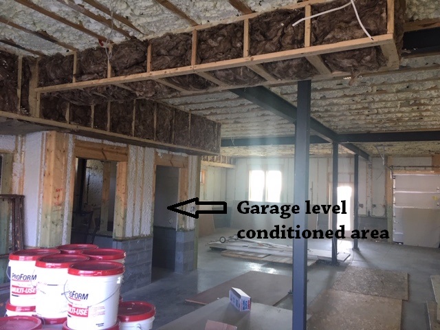
Even when a garage is attached to the home, it is still outside the thermal envelope of the home, so the walls and ceiling separating it from the rest of the home must be insulated and air sealed just like any exterior walls or floors above unconditioned space. For the Insulation installed in the floor above a garage to be effective, it must be in full contact (continuous alignment) with the subfloor above and with the rim joists on all sides and any seams or holes in the subfloor and rim joists must be sealed. This air sealing provides a continuous air barrier which serves two purposes: it keeps wind from blowing through the insulation and robbing it of its thermal value and, even more importantly, it prevents garage air pollutants like car exhaust and chemical fumes from migrating into the home (EPA 2008).
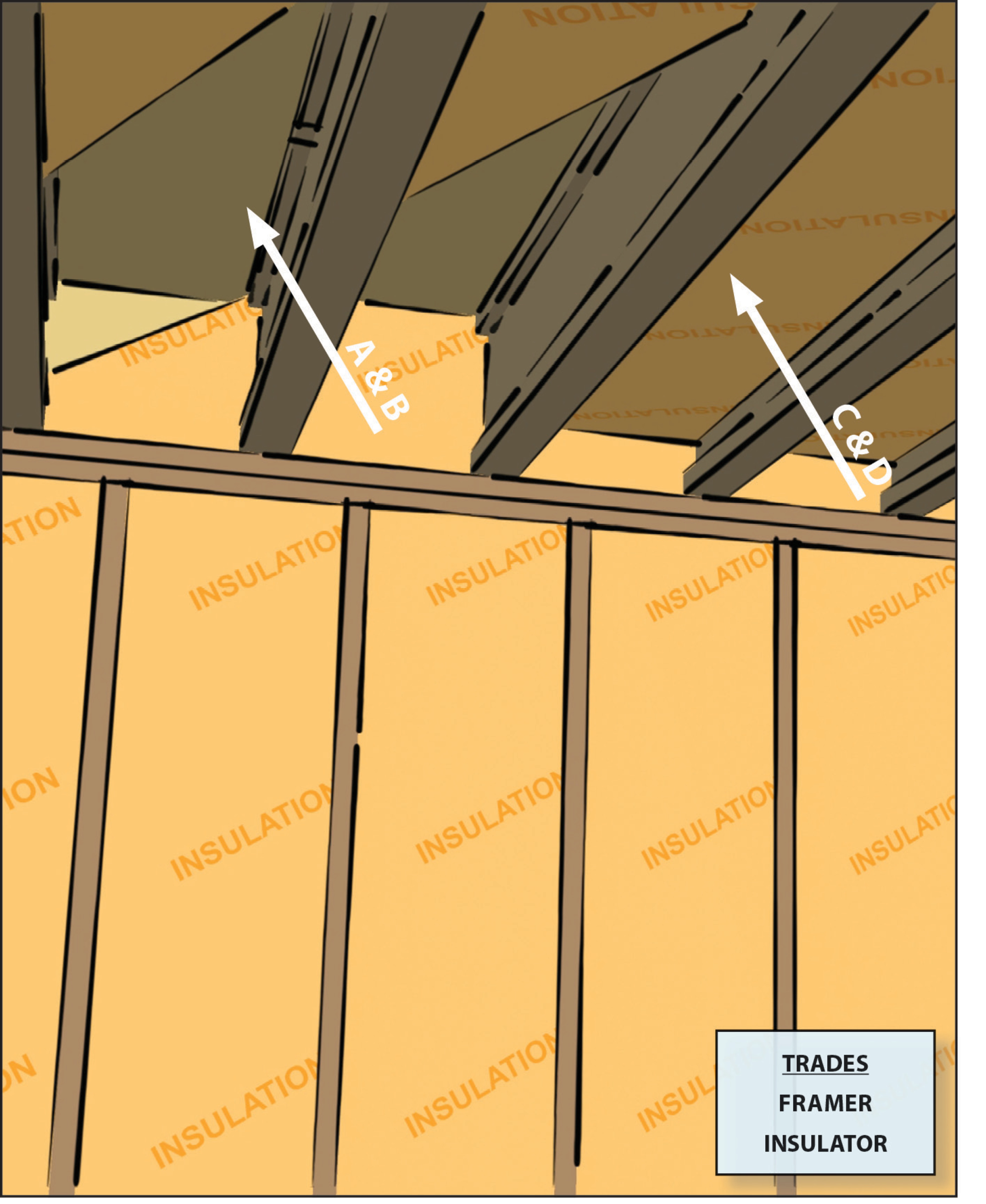
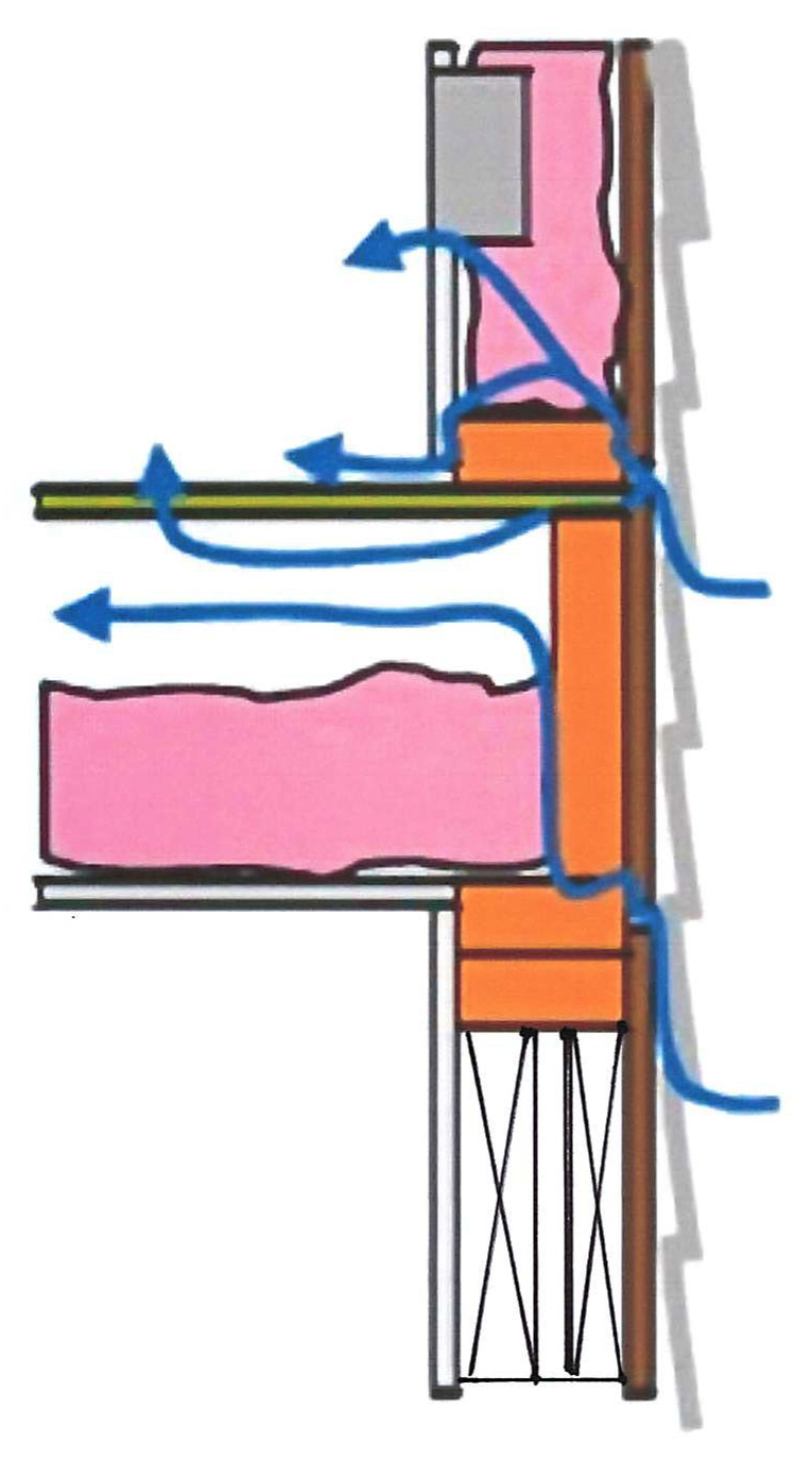
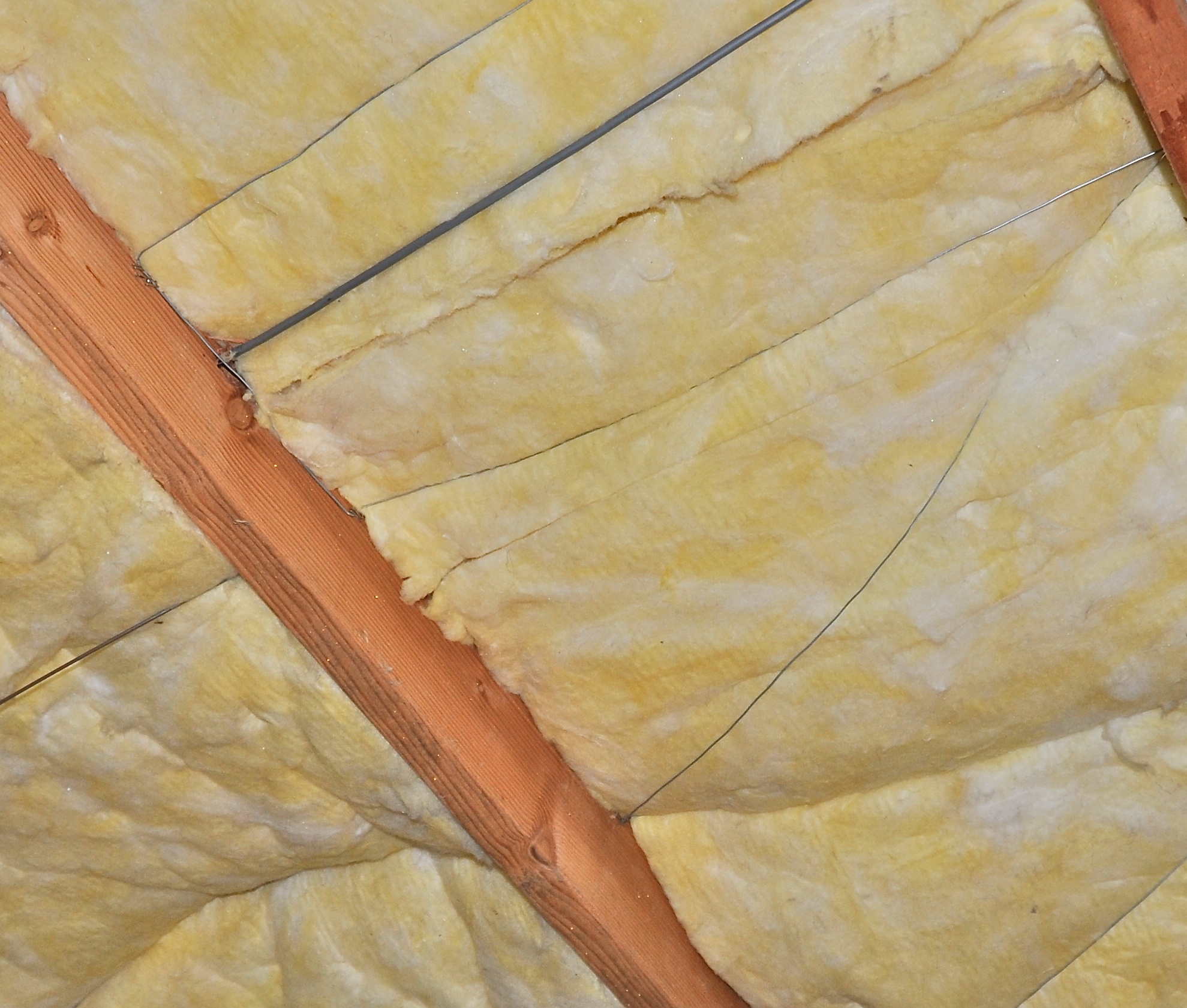
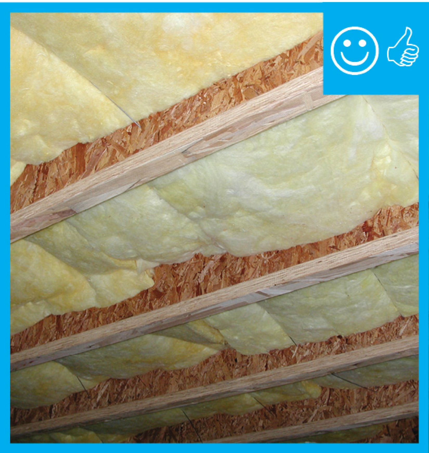
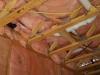
When the insulation is not in contact with the subfloor (as shown in Figure 1), it creates space for air to flow, either from unsealed exterior walls or from convective loops of air currents. The moving air pulls heat from the floor system, robbing the insulation of its effectiveness and causing cold floors above. The solution to eliminating these thermal short circuits is two-fold: First, completely air seal the floor system, paying particular attention to sealing the band/rim joist area to create a continuous air barrier. Second, install the ceiling insulation in full alignment (continuous contact) with this air barrier (EPA 2008).
How to Insulate and Air Seal the Floor above an Attached Garage
- Install a subfloor that can serve as a continuous air barrier between the garage and the rooms above. In most cases, this air barrier will be plywood or OSB floor sheathing. Install the subfloor sheathing panels according to APA Sturd-I-Floor recommendations, which includes the following (APA 2011):
- Install subfloor in panel widths that align with the framing (typically 16-, 20-, or 24-inches on-center).
- Stagger subfloor panel end joints.
- Use tongue-and-groove subfloor panels or install blocking beneath panel joints.
- Apply construction adhesive or caulk at panel seams and between subfloor panel and framing members.
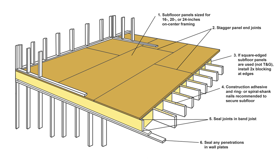
- Air seal the band and rim joists and any penetrations.
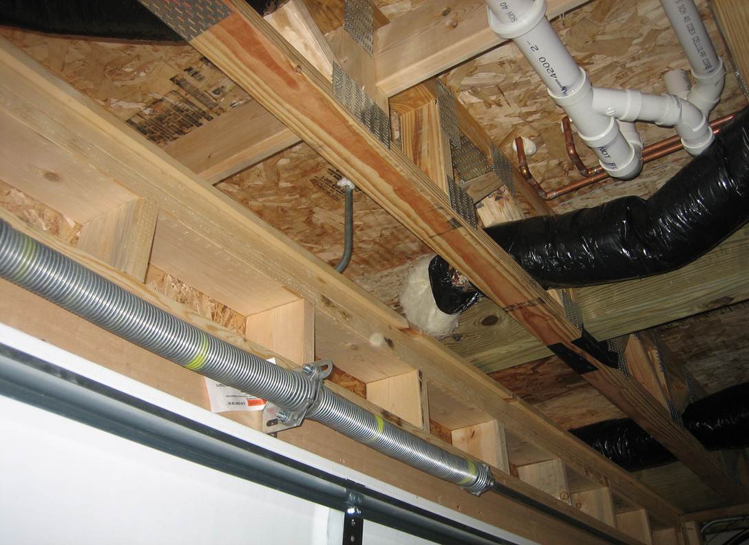
- Block off any open floor joists running from the garage ceiling to under other parts of the home to prevent the infiltration of airborne pollutants (EPA 2008). See the guide Garage Rim/Band Joist Adjoining Conditioned Space for more information. Use an air barrier material such as plywood, sheathing, rigid foam, or OSB (see Figure 4). Do not use batt insulation for air sealing.
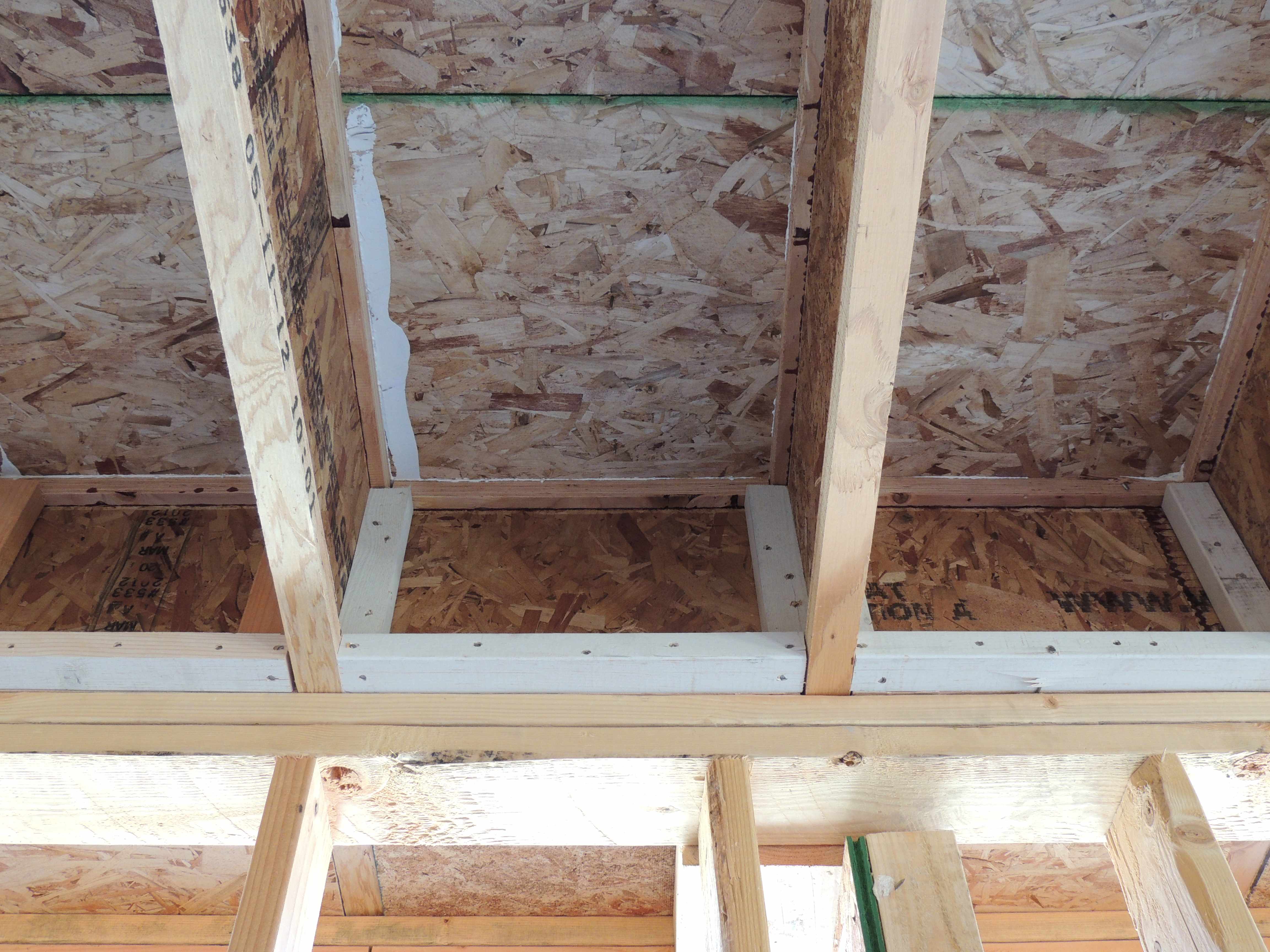
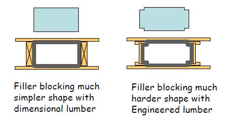
- If I-joists are used, the blocking material must be cut to fit the shape. This can be done with filler strips as shown in Figure 4. Or, the corners of the blocking may be cut to fit around the I-joist flanges, as shown in Figure 5.
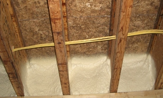
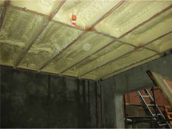
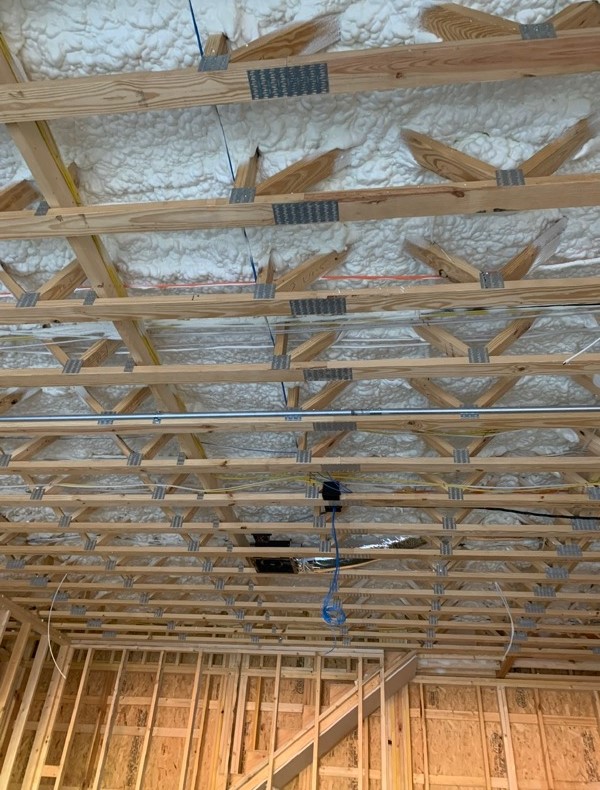
- Seal the edges of the blocking with a one- or two-part foam sealant or caulk. Foam sealant will work better (and last longer) than caulk. Spray foam can be used to cover the whole air barrier (Figure 6) to fill small voids and cracks to effectively stop air flow, while also providing additional R-value (DOE 2012).
- Install insulation in the floor joists.
- Insulation should be fully "aligned" with the air barrier, i.e., in full contact with the subfloor above. There can be no gaps between the insulation and the sheathing above it (EPA 2011).
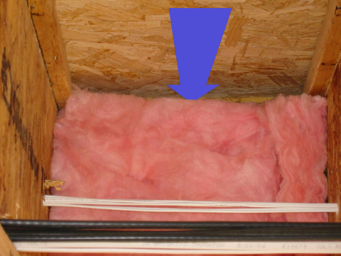
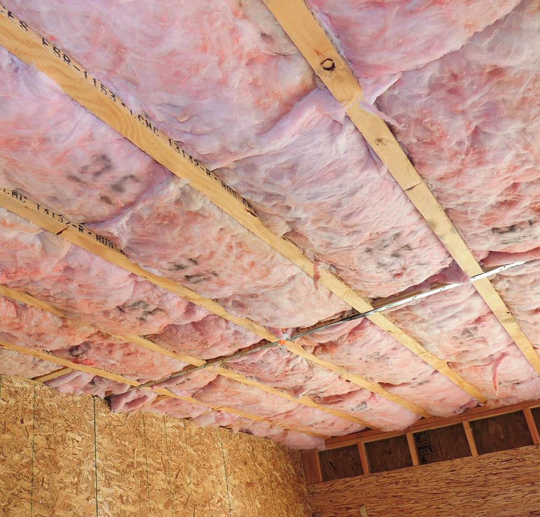
- Batt insulation should fit tightly between the floor joists but avoid gaps, compressions, or voids. Batts should be fully lofted (not crammed or compressed into the space, see Figure 7). Batts should be cut lengthwise to fit narrow joist bays, and split to fit neatly around electrical wiring running across joist bays. See the guide Insulation Installation Achieves RESNET Grade 1 for more on quality installation.
- Blown-in fiberglass or cellulose is especially effective for insulating garage ceilings when webbed floor trusses are used because it can fill in voids around the trusses. First install netting or the ceiling drywall to hold the insulation. Install the blown-in insulation to the correct volume and density to maintain contact with the subfloor above and prevent settling. Confirm with the insulation manufacturer or installer that the drywall will hold the weight of the insulation needed (EPA 2008).
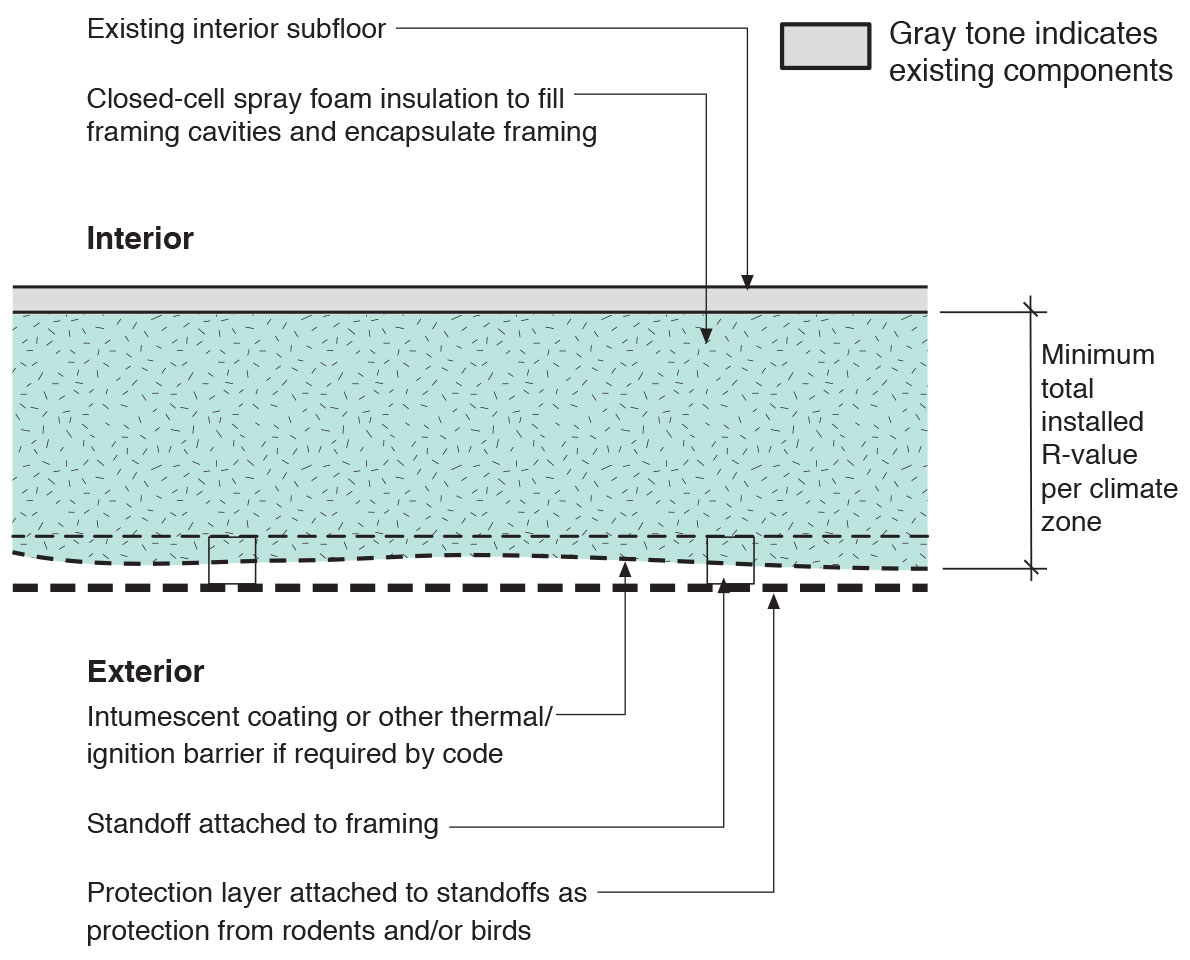
- Spray foam insulation can be used to insulate the floor above a garage as well as the band joist. Spray foam provides high R-value and a continuous air barrier in one labor-saving application. To qualify as an air barrier, open-cell spray foam must have a finished thickness ≥ 5.5 inches and closed-cell spray foam must have a finished thickness ≥ 1.5 inches (EPA 2011).
- Support insulation.
- Batt insulation must be installed to sufficient depth that it will stay in contact with the subfloor above when drywall is installed below it. If drywall will not be installed, install metal staves or mechanically fastened wire to keep batts in continuous contact with the subfloor above.
- Blown insulation must be installed at sufficient depth and density to completely fill the floor joist cavities from the ceiling drywall to the subfloor above.
- Spray foam alone requires no additional support. If spray foam is used in combination with batt or blown insulation, the batt or blown insulation must be supported or installed at sufficient depth to fill the ceiling cavities.
Ensuring Success
Blower door testing conducted as part of whole-house energy performance testing, may help indicate whether air leakage at the floor has been successfully sealed. Infrared imaging with an infrared camera may be used to determine air leakage at the floor over a garage. For best results, scan twice. First, scan under static conditions before blower door testing has been conducted. This will allow the technician to evaluate the integrity of insulation behind the drywall if the garage ceiling has been finished. Conduct a second scan with the blower door running in depressurization mode and the door between the house and the garage open. This will demonstrate the integrity of the air barrier, showing where air leakage has infiltrated the framing and seeped through insulation. With the blower door pressurizing, the garage door closed and the door to the house open, check for air leaks in the floor and near the rim joist with a smoke pencil. A smoke trail moving away from the smoke pencil indicates a leak to the unconditioned space that should be sealed.
Region
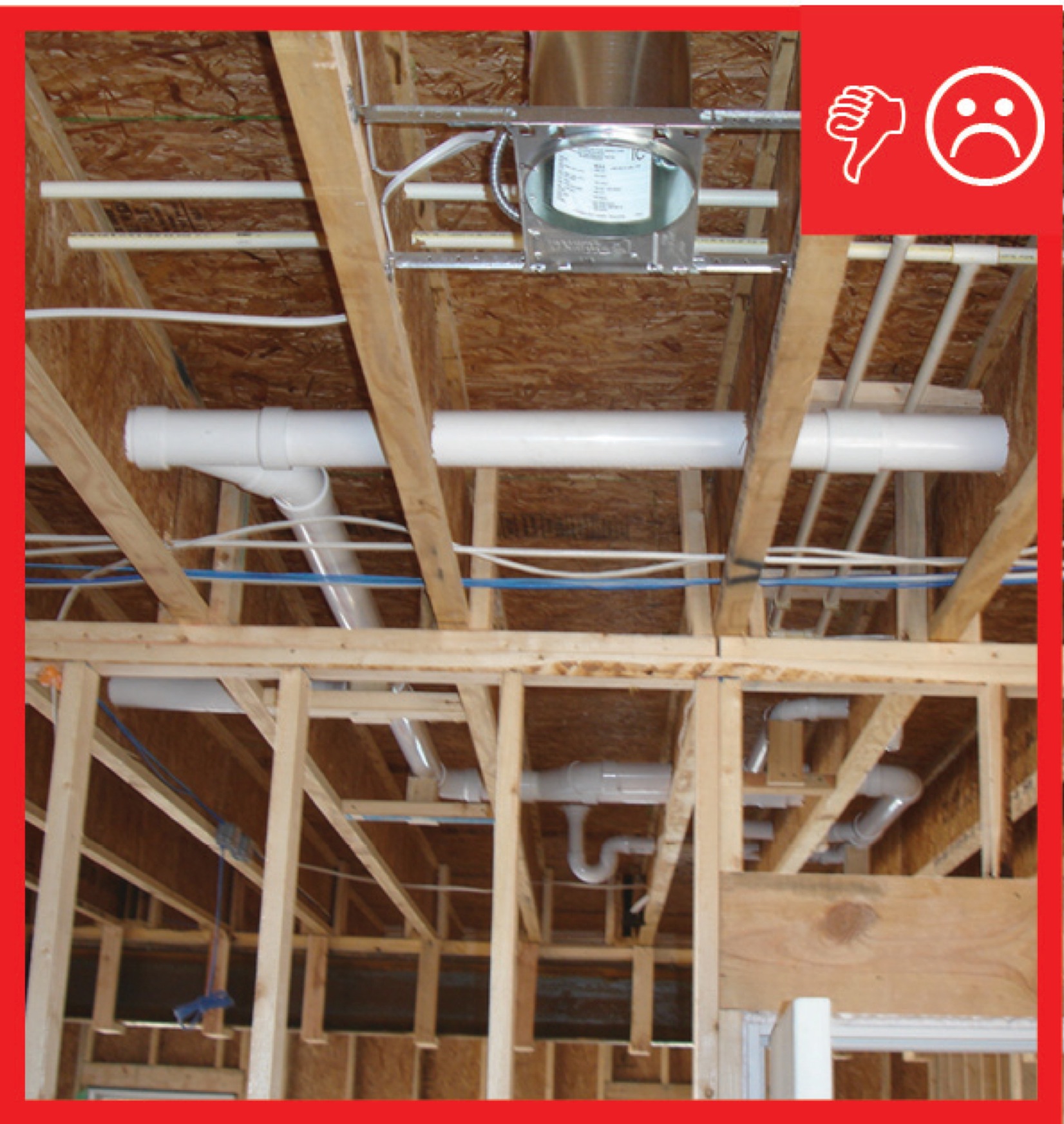
In cold climates, avoid installing plumbing in floors over garages because the pipes could freeze.
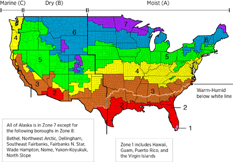
Install insulation in amounts that meet or exceed code-required levels for your climate zone.
The map in Figure 1 shows the climate zones for states that have adopted energy codes equivalent to the International Energy Conservation Code (IECC) 2009, 12, 15, and 18. The map in Figure 2 shows the climate zones for states that have adopted energy codes equivalent to the IECC 2021. Climate zone-specific requirements specified in the IECC are shown in the Compliance Tab of this guide.

Training
Right and Wrong Images
Source
Guide describing details that serve as a visual reference for each of the line items in the Thermal Enclosure System Rater Checklist.

Source
Guide describing details that serve as a visual reference for each of the line items in the Thermal Enclosure System Rater Checklist.

Source
Guide describing details that serve as a visual reference for each of the line items in the Thermal Enclosure System Rater Checklist.
Source
Guide describing details that serve as a visual reference for each of the line items in the Thermal Enclosure System Rater Checklist.
Source
Source
Source
Guidebook providing useful examples of high performance retrofit techniques for the building enclosure of wood frame residential construction in a cold and somewhat wet climate.
Presentations
Videos

CAD Files


Compliance
More Info
Case Studies
References and Resources
*For non-dated media, such as websites, the date listed is the date accessed.
Contributors to this Guide
The following authors and organizations contributed to the content in this Guide.
Pacific Northwest National Laboratory
Building Science Corporation, lead for the Building Science Consortium (BSC), a DOE Building America Research Team
Sales
Fully Aligned Air Barriers = Whole-House Draft Barrier
Technical Description
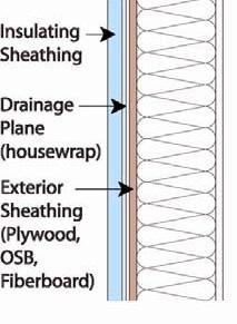
A whole-house draft barrier is a continuous layer of air-tight materials that block air leaks. This barrier can be integrated with other materials to also function as a water barrier, thermal barrier, and vapor barrier. For example, rigid foam insulation can be used to block thermal flow as well as air flow when seams are sealed with tape, caulk, adhesives, or liquid-applied sealants. Some rigid foams have an integrated water control layer as well. Additionally, drywall can serve as an interior air barrier when the seams are taped and spackled, and caulk, spray foam, or gaskets are used to seal around wiring, plumbing, and other penetrations. It also serves as the vapor barrier when finished with paint. Insulation should be in full contact with the air barrier layer.
Questions? Comments? Contact our webmaster.