Showing results 1 - 50 of 55
Image
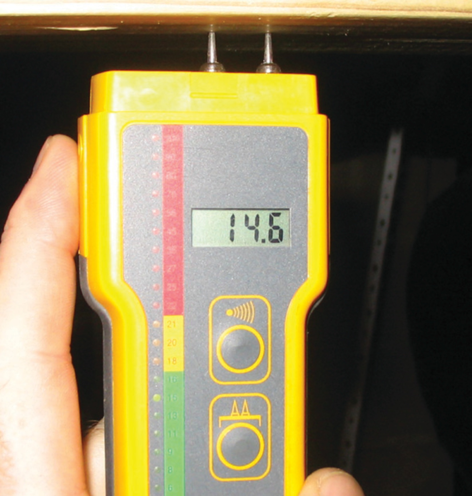
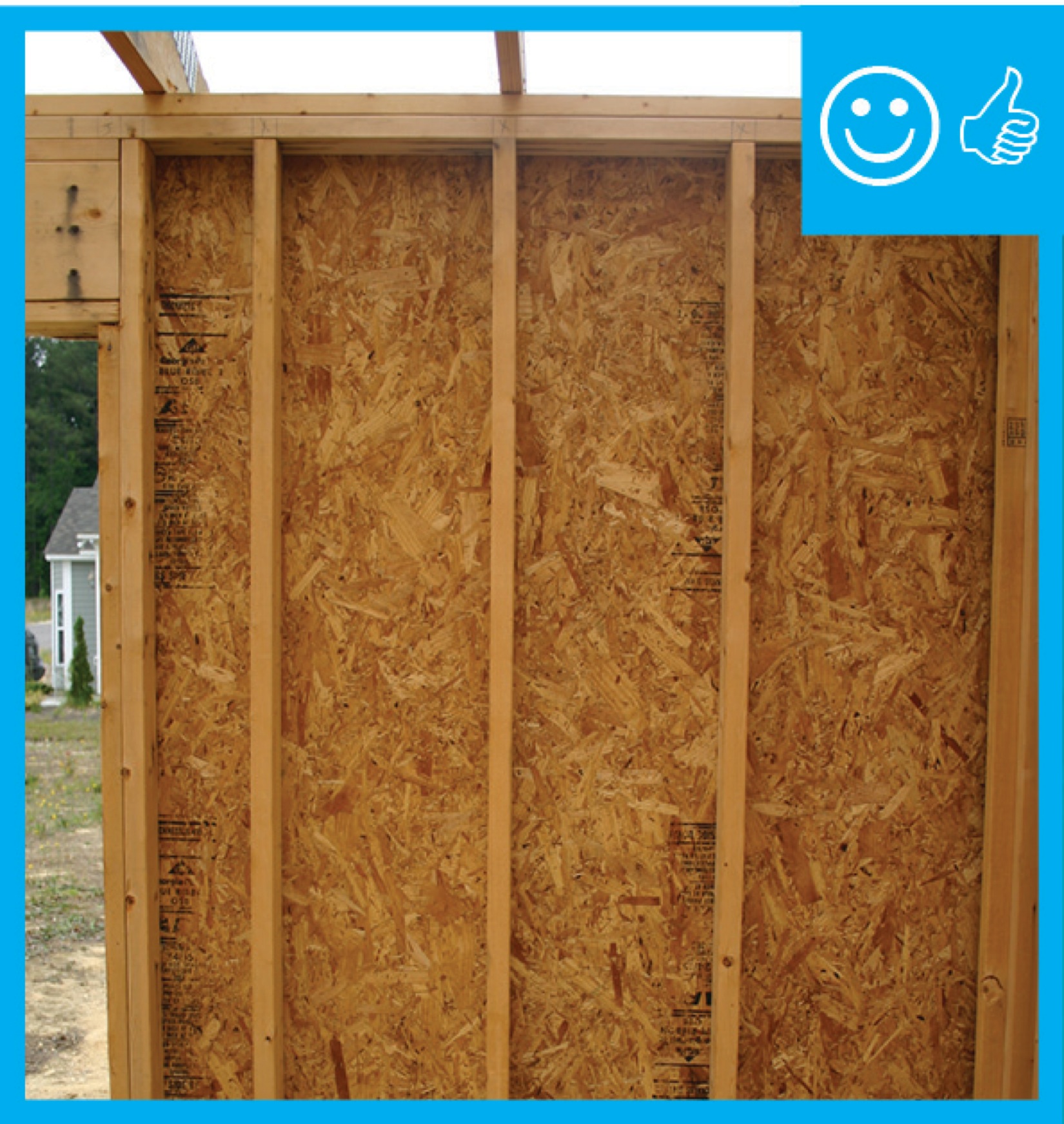
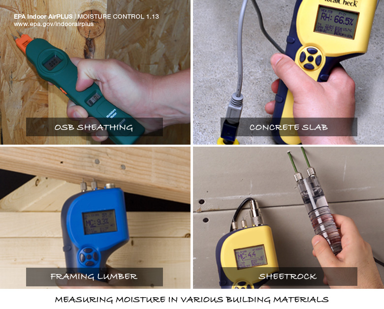
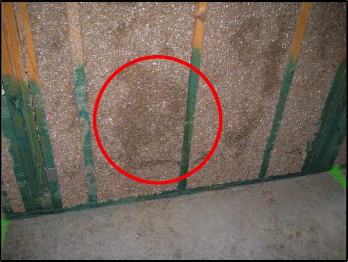
A moisture meter verifies that the moisture of the framing is below the recommended 18%.
Image
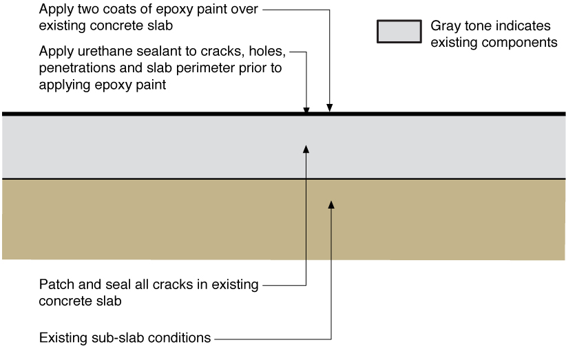
An uninsulated (or existing insulated) basement slab is retrofitted to reduce moisture transmission by sealing with epoxy paint.
Image
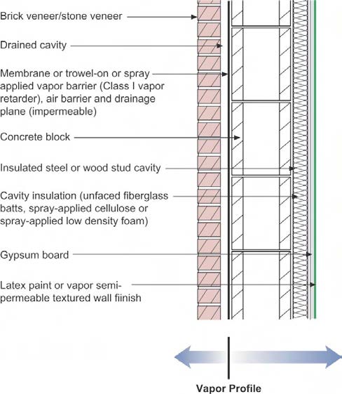
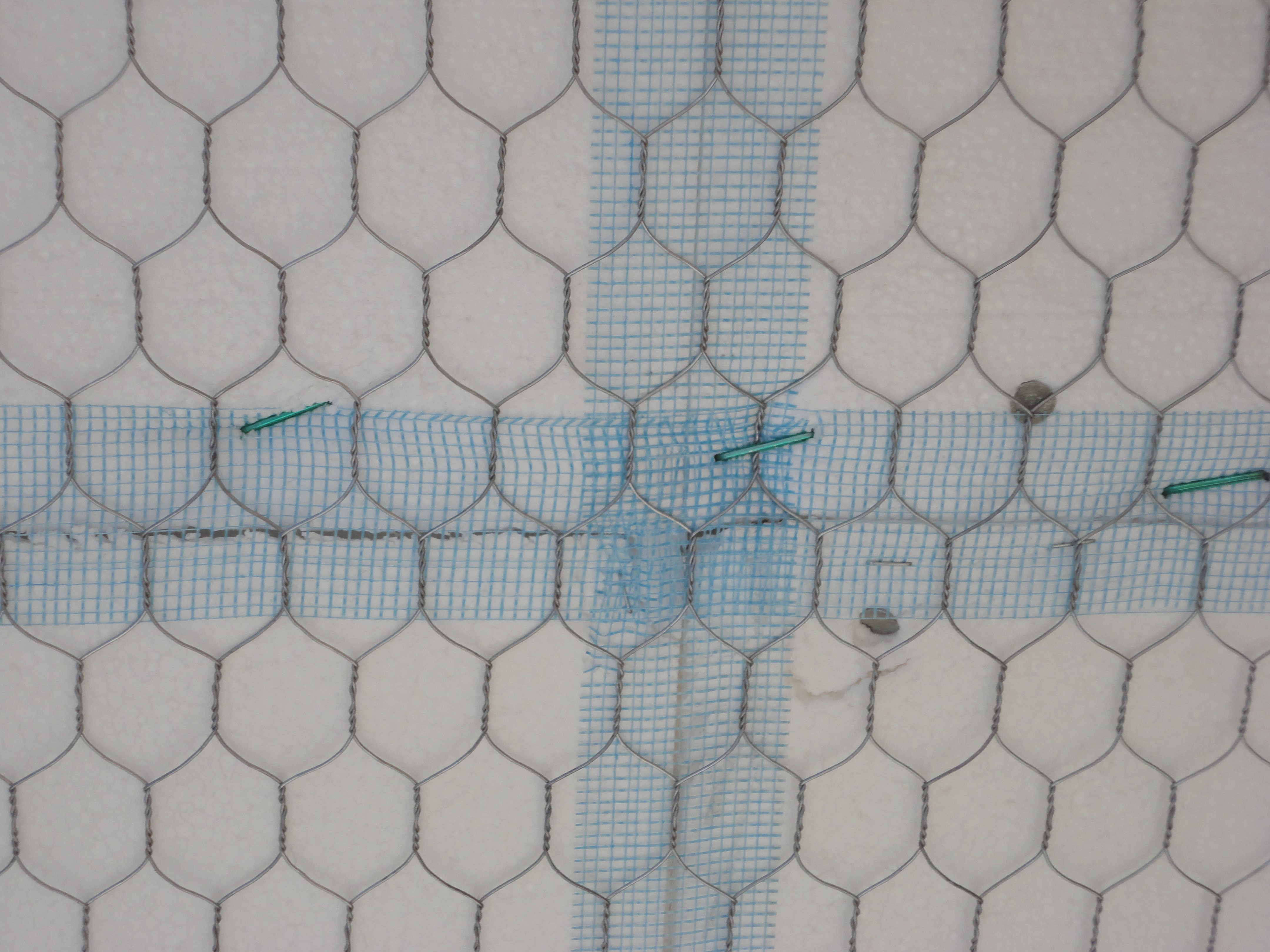
Brick wall assembly for a hot-humid climate with no Class I vapor retarder and with an air gap (drained cavity) to dissipate vapor driven into the wall by the sun.
Image
Image
Image
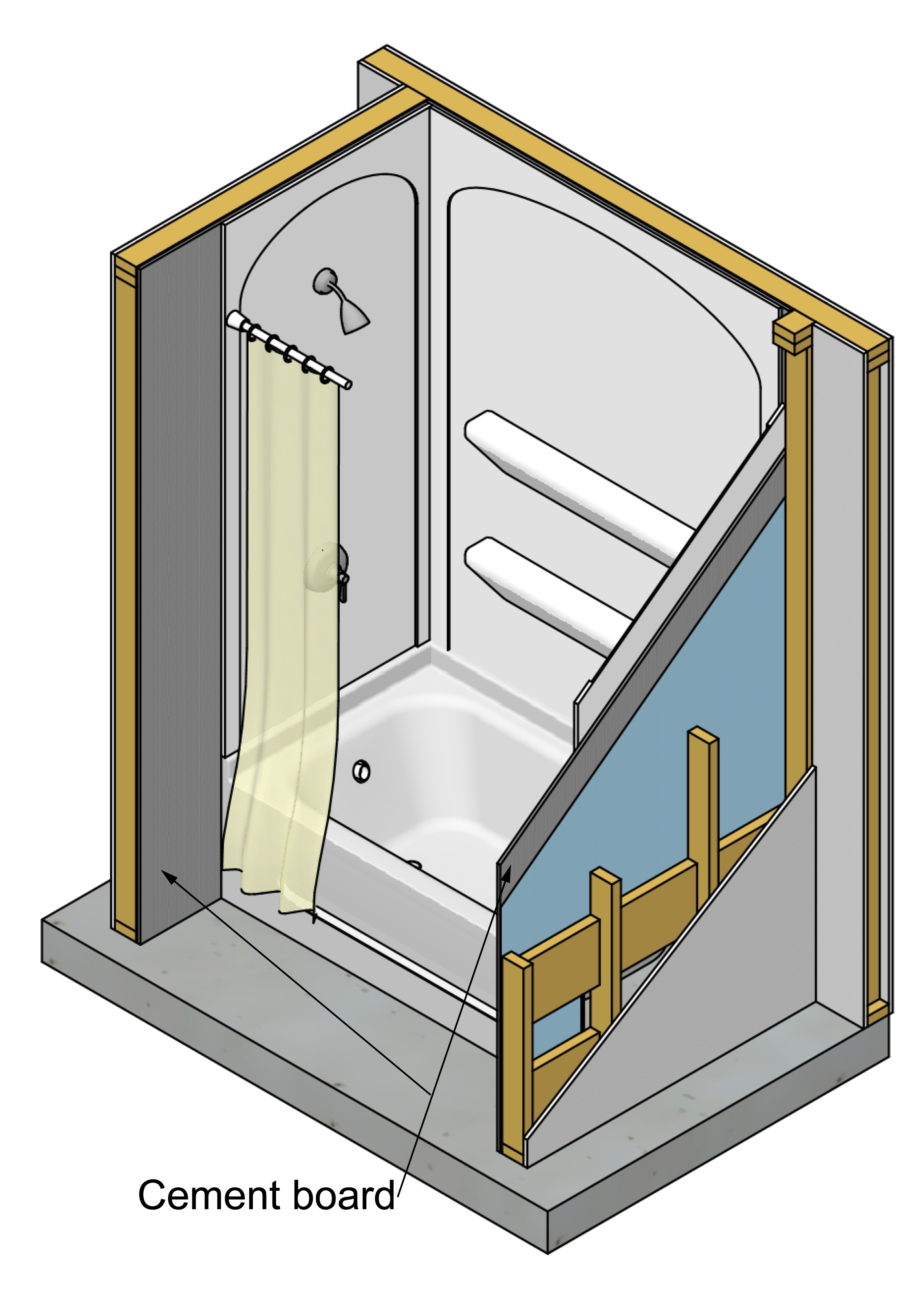
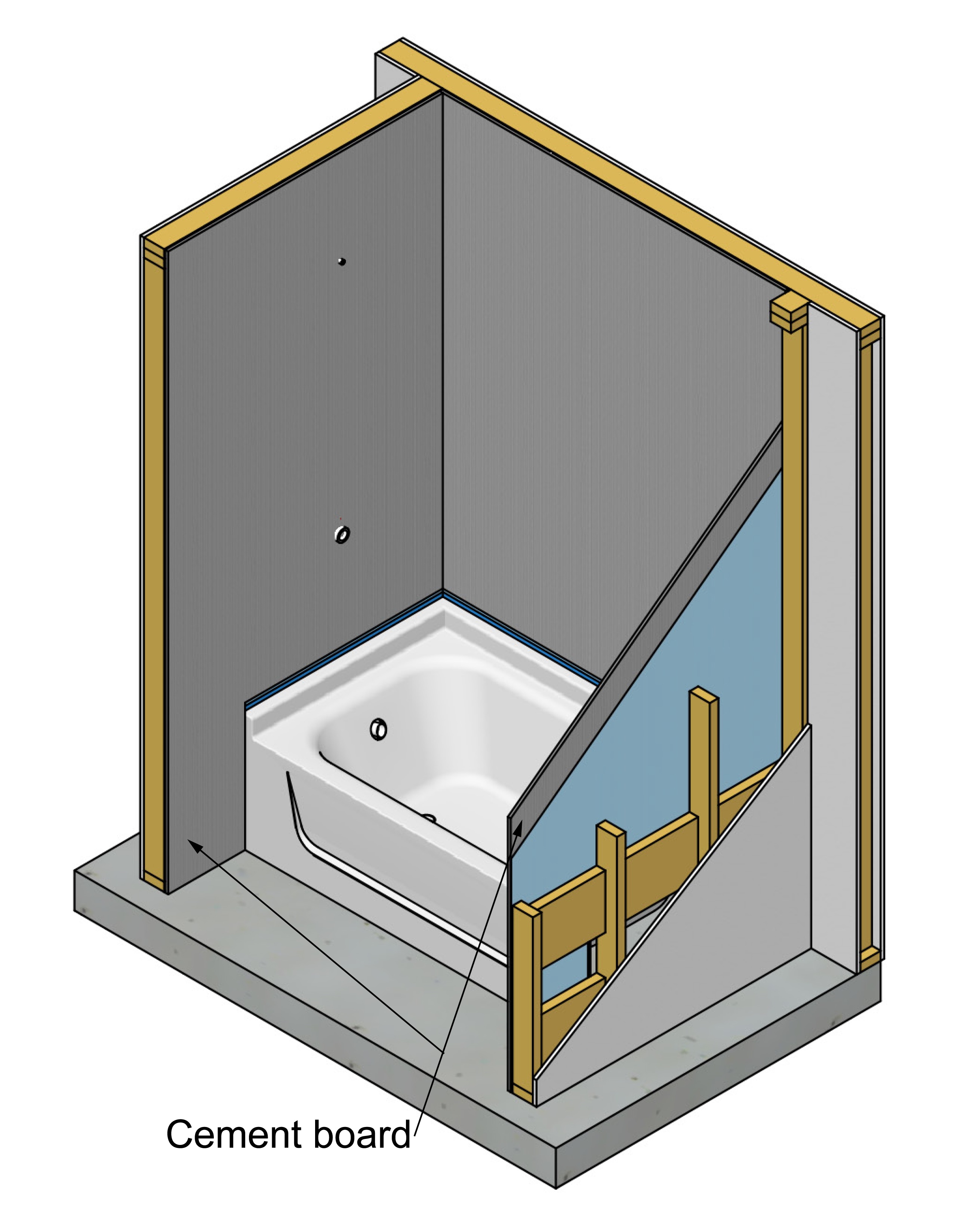
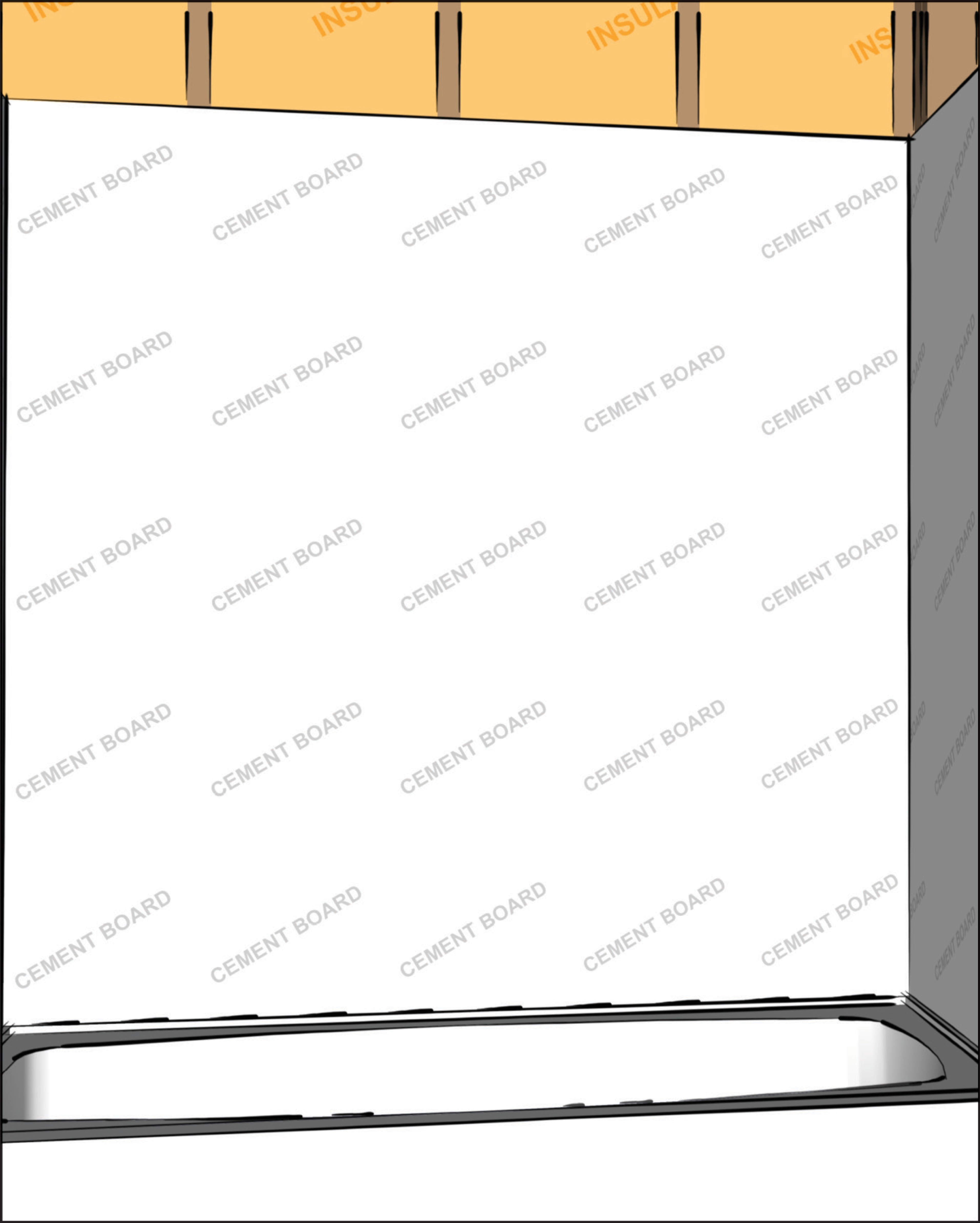
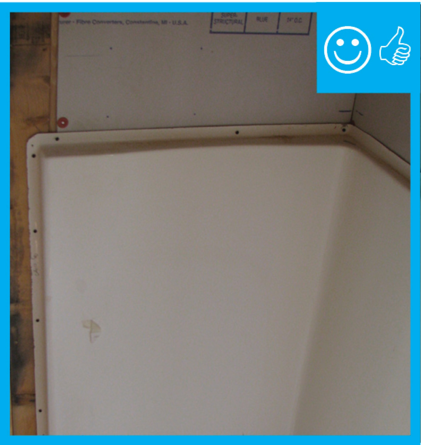
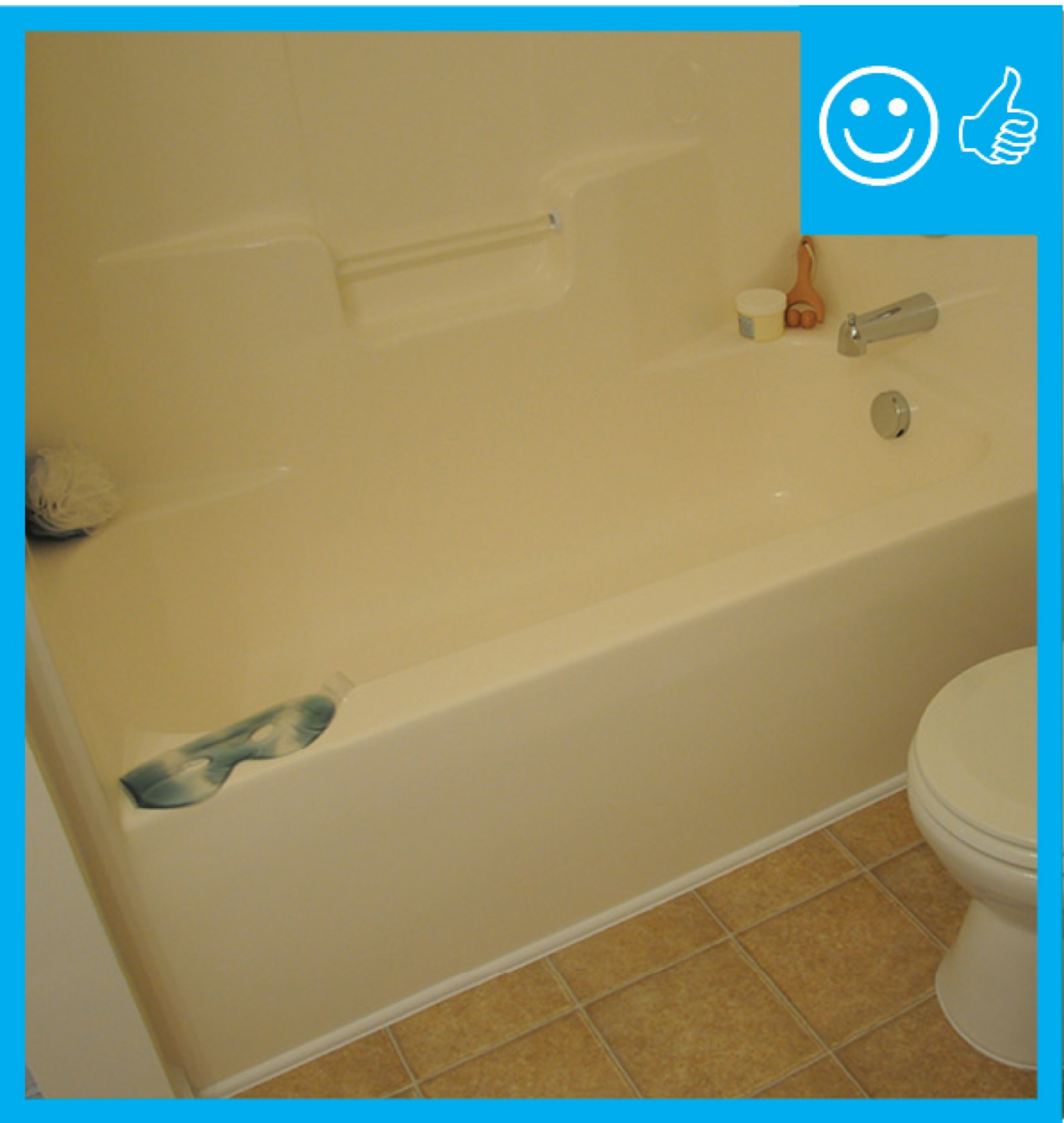
Cement board (shown in dark grey) is installed behind an installed tub and shower surround.
Image
Image

Image
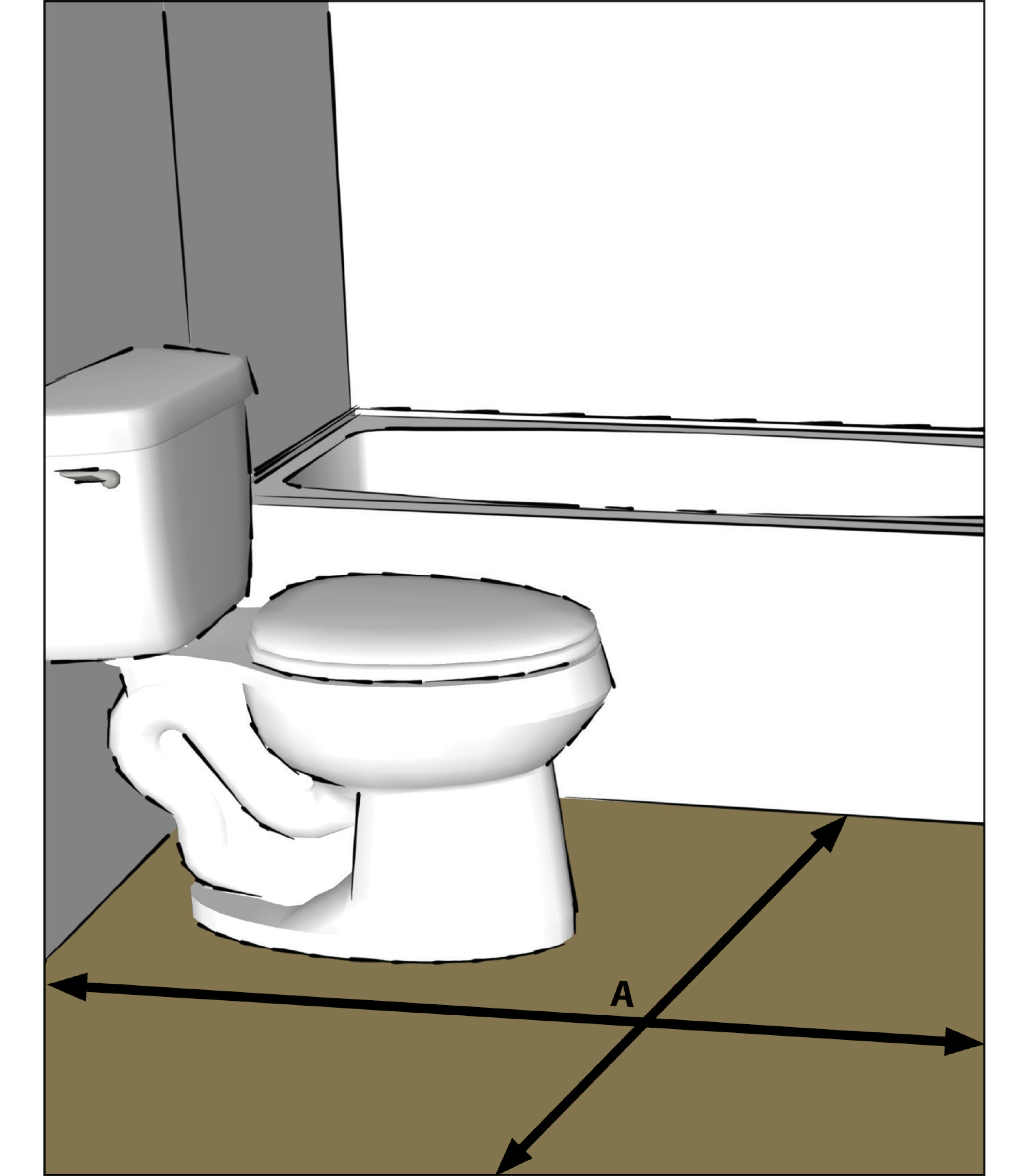
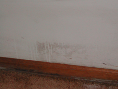
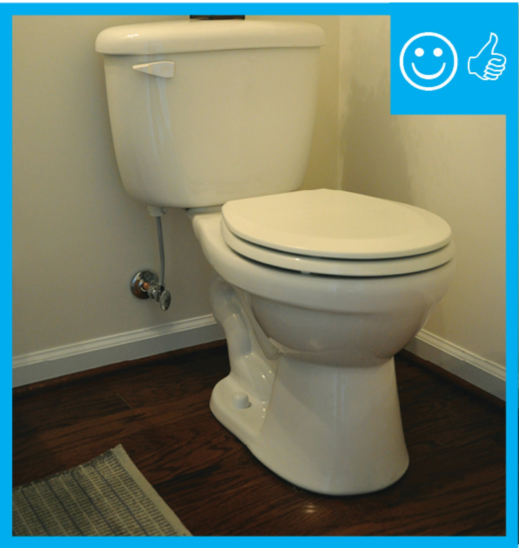
Do not install carpet in areas that are likely to get wet, such as bathrooms, kitchens, entry ways, or laundry rooms.
Image

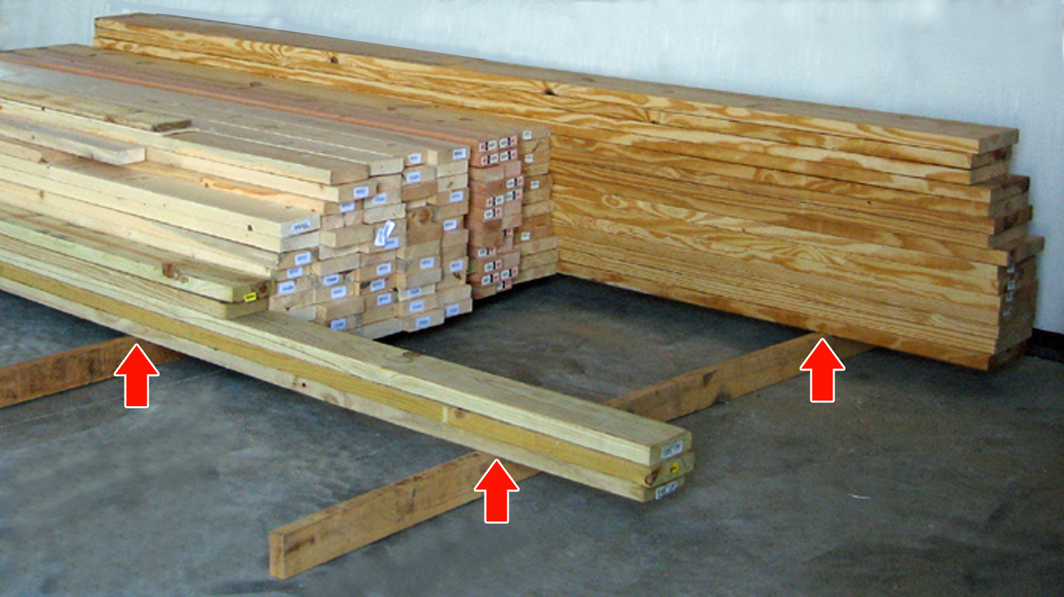
Do not install lumber, plywood, or other building materials that show visible signs of water damage or mold.
Image
Image
Image

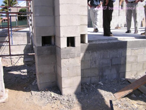
ICF bricks are stacked to form hollow walls that are reinforced with steel rebar before the concrete is poured in
Image
Image

Image

Image
Image
Image
Image
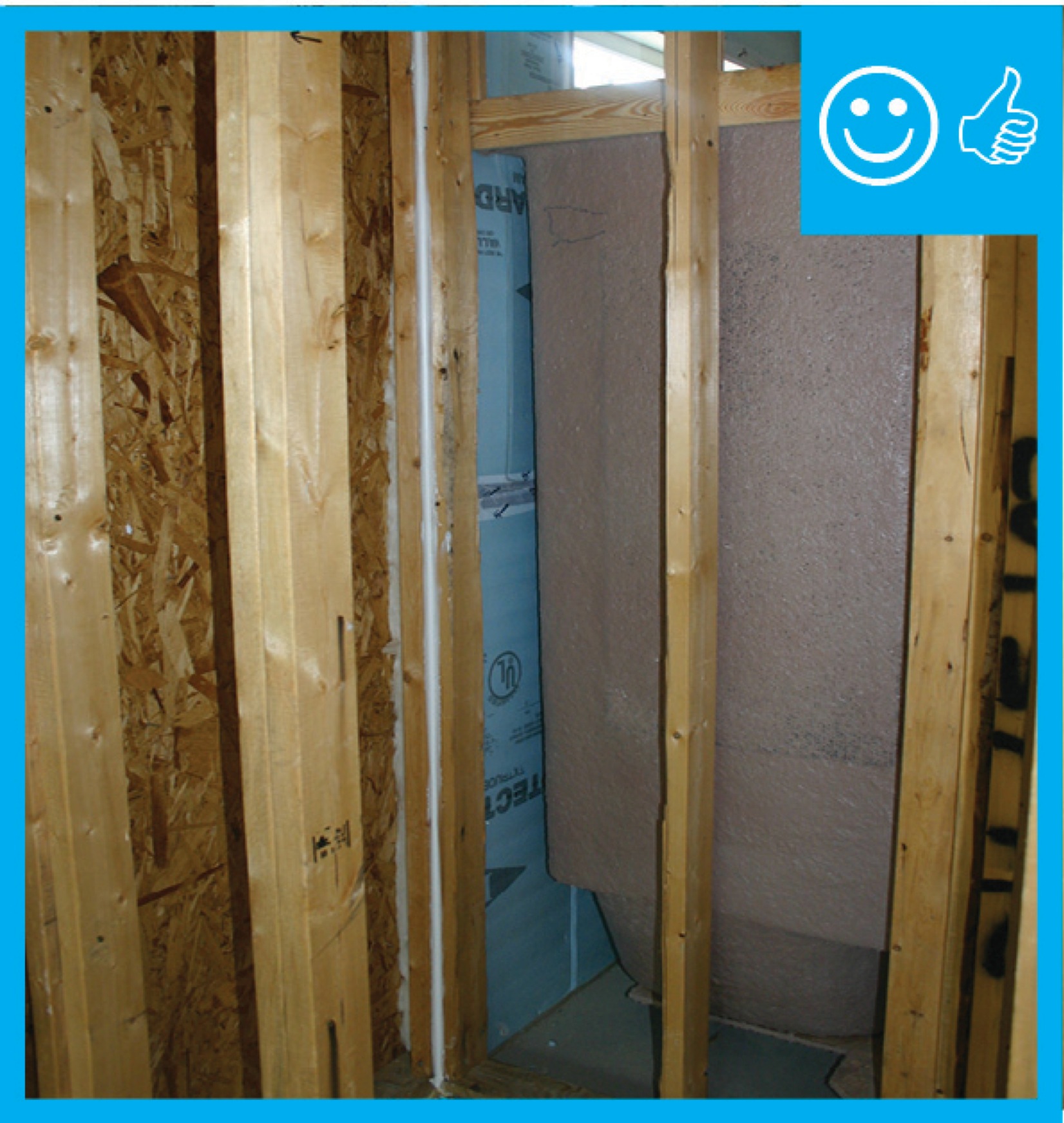
Right – Moisture-resistant backing material has been used above and behind the tub enclosure.
Image
Image
Image
Image
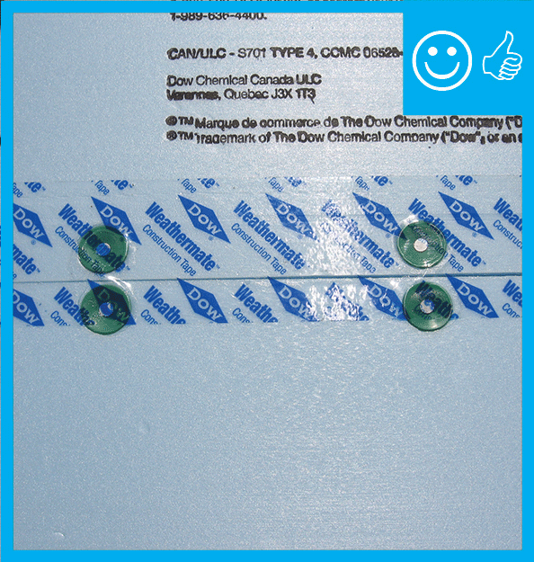
Right – Two-thirds of acrylic tape is offset above the joint and over and above the fasteners
Image
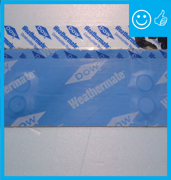
Right – two-thirds of the blue butyl flashing tape is above the sheathing seam; the top edge of the butyl flashing tape is covered with clear sheathing tape that is also offset so two-thirds is above the top edge of the butyl flashing.
Image
Right: All joints in the rigid foam are taped to keep stucco out of joints for even drying. Mesh tape (shown here) is used with expanded polystyrene (EPS); acrylic sheathing tape or self-adhered membrane is used with XPS
Image
Image
Image
Image
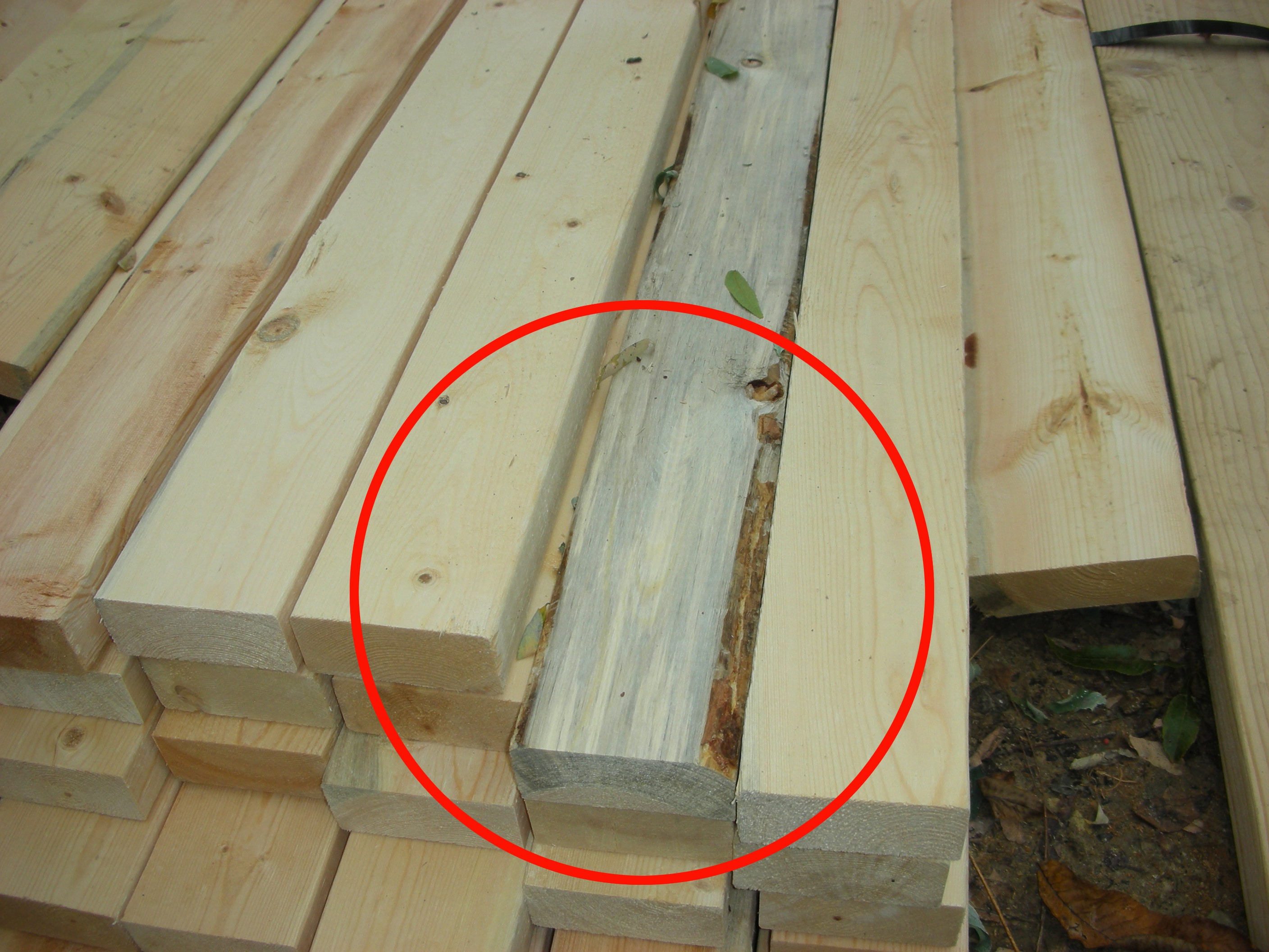
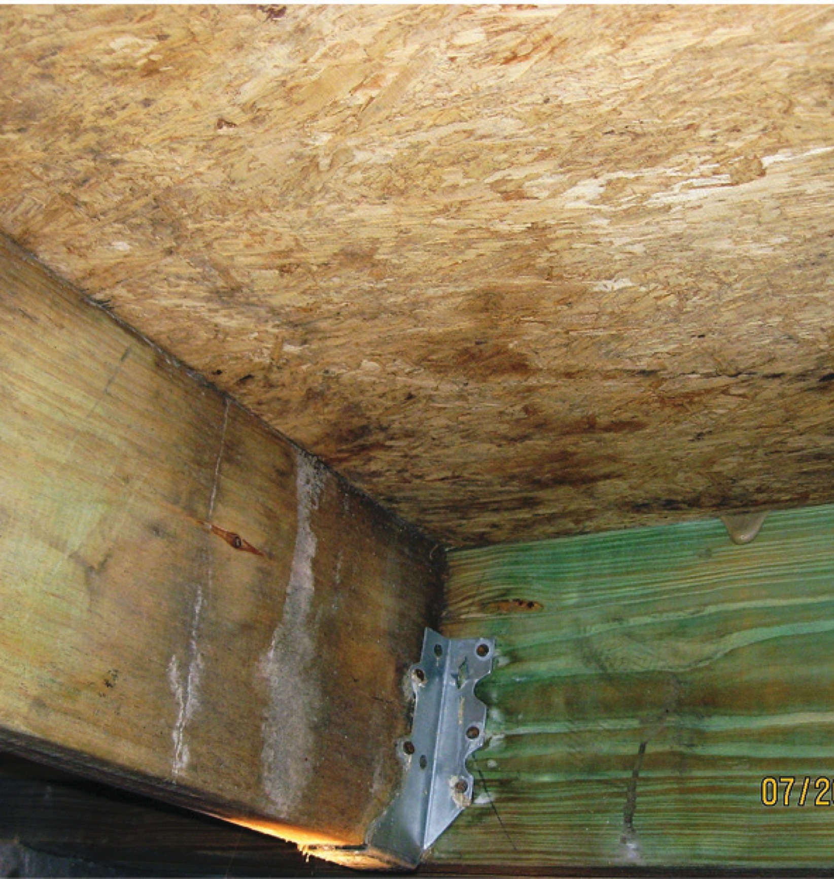
The board in the center of this photograph shows blue stain (not lumber mold), a discoloration of the wood caused by a fungus affecting the living tree, which did not harm the structural integrity of the wood.
Image

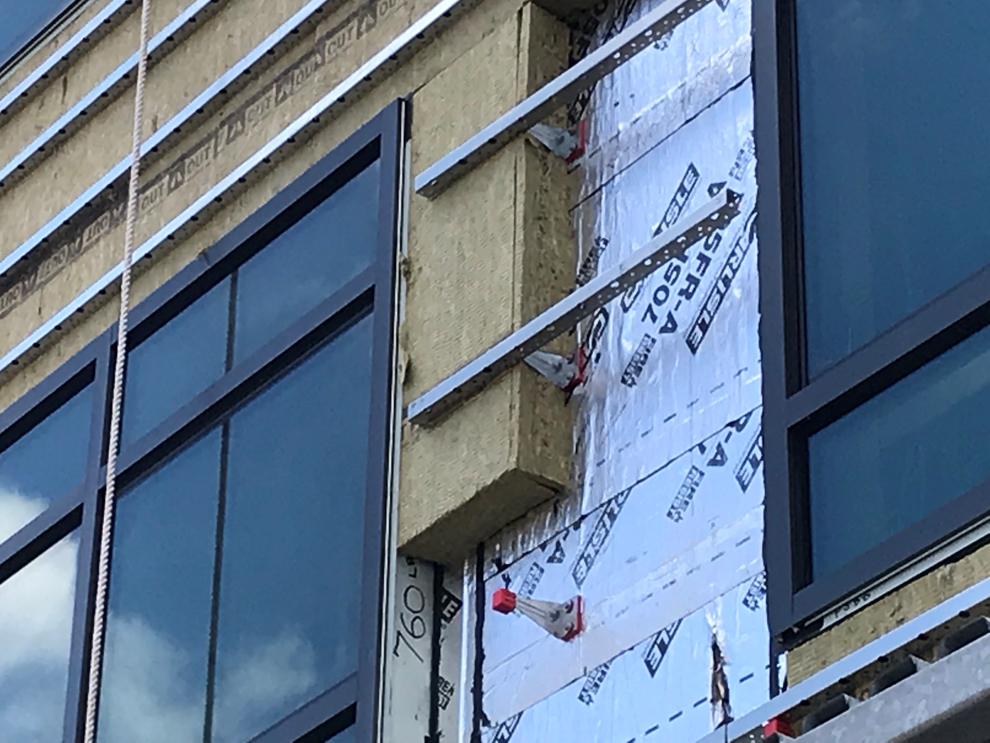
The windows in this building are connected to the fully adhered water and air control layer using fluid-applied flashing
Image
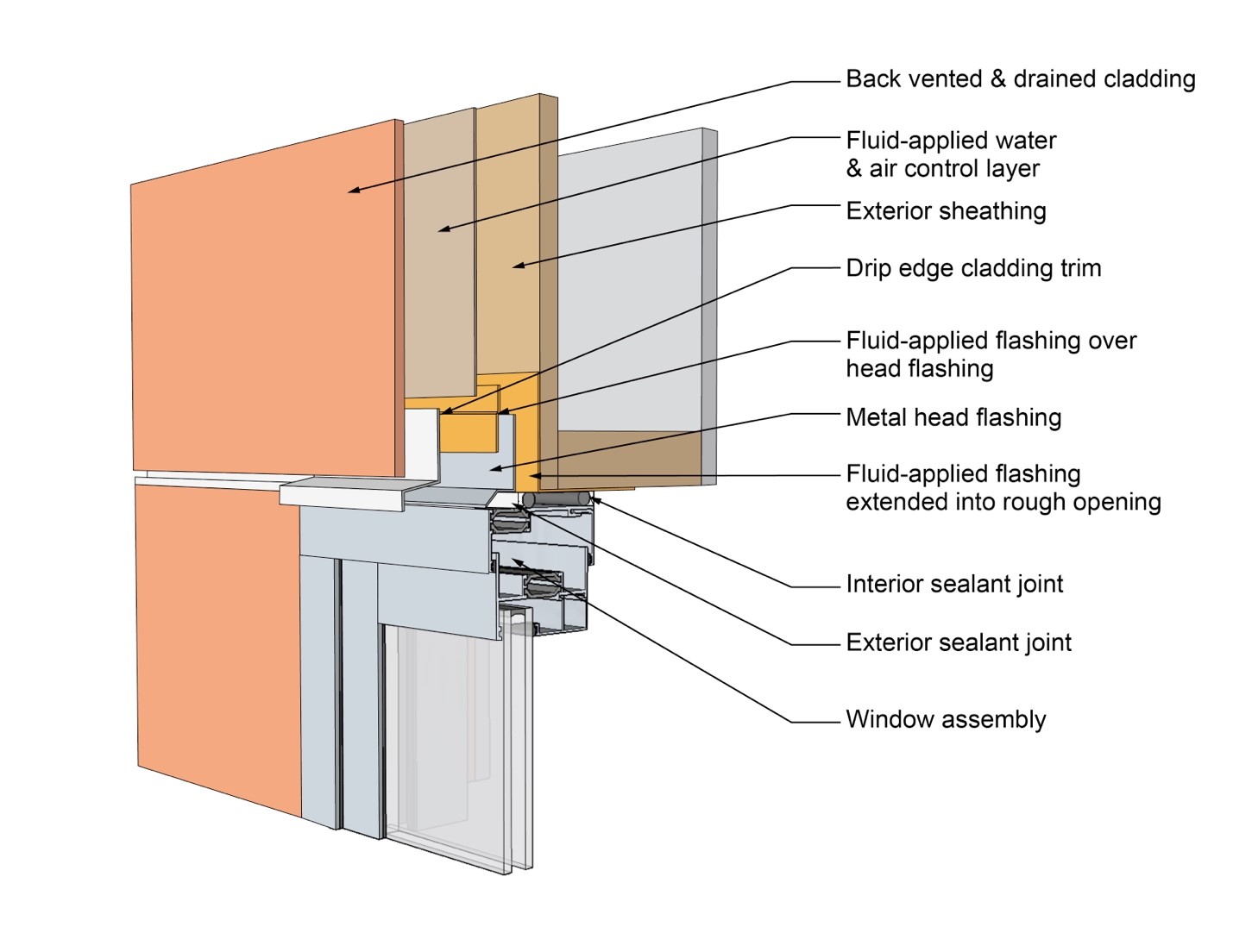
This drawing shows key head details for a window installation using a fluid-applied flashing on a wall with a fluid-applied water and air control layer
Image
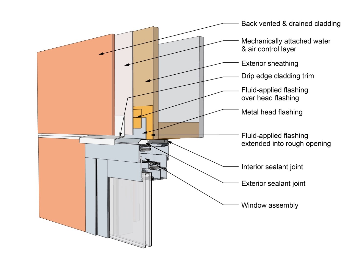
This drawing shows key head details for a window installation using a fluid-applied flashing on a wall with a mechanically attached water and air control layer
Image
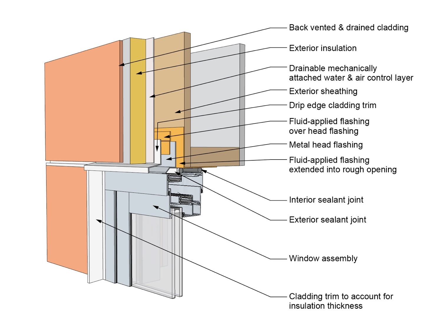
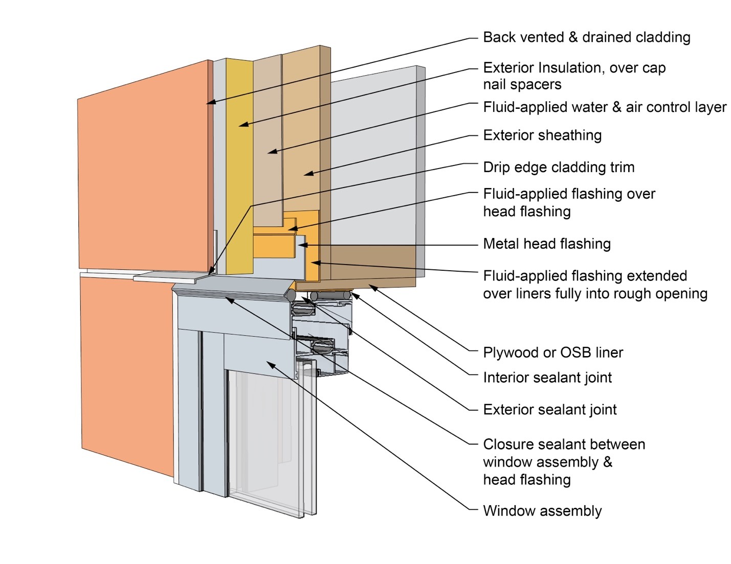
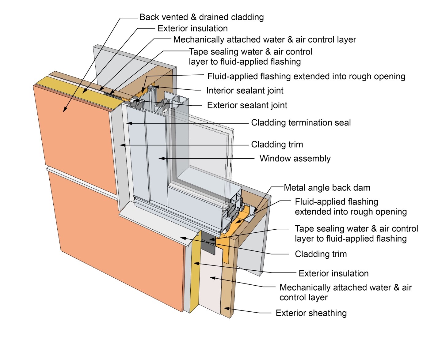
This drawing shows key head details for a window installation using a fluid-applied flashing on a wall with a mechanically attached water and air control layer and continuous insulation
Image
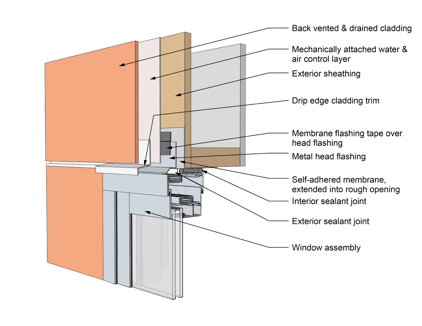
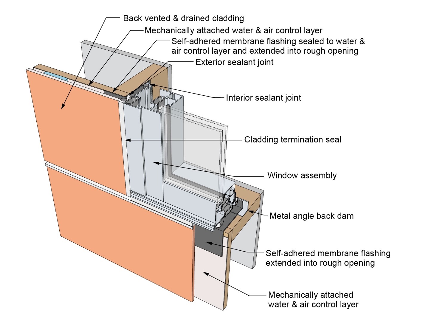
This drawing shows key head details for a window installation using a self-adhered membrane tape flashing on a wall with a mechanically attached water and air control layer
Image
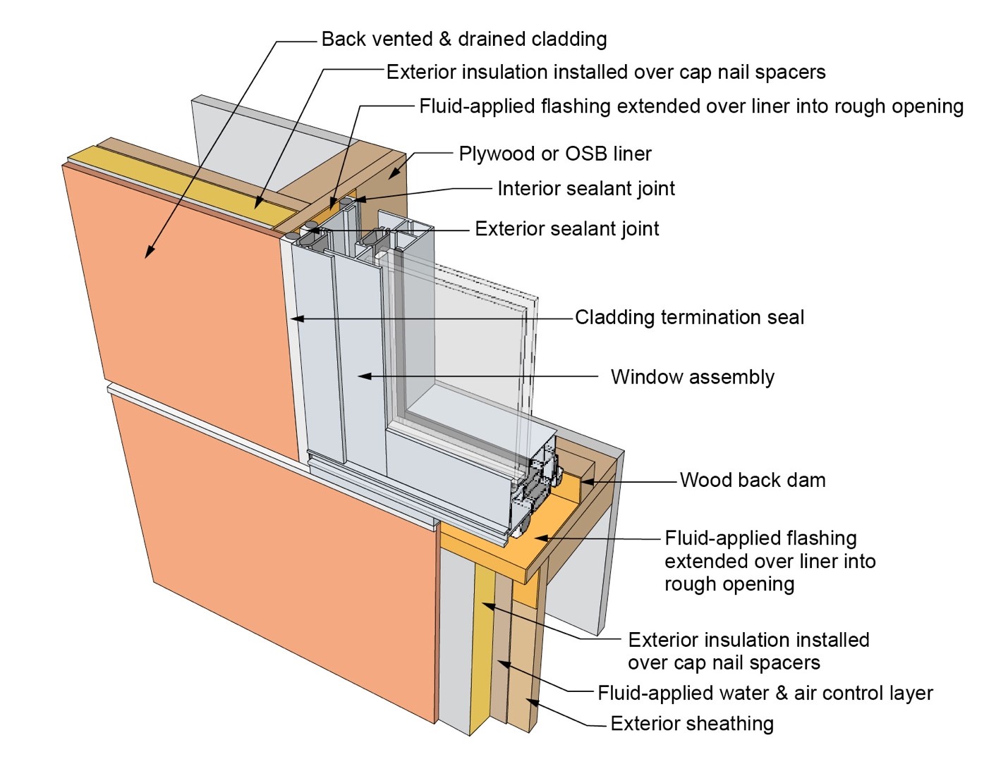
This drawing shows key head details for an “outie” window installation using a fluid-applied flashing on a wall with a fluid-applied water and air control layer and continuous insulation
Image
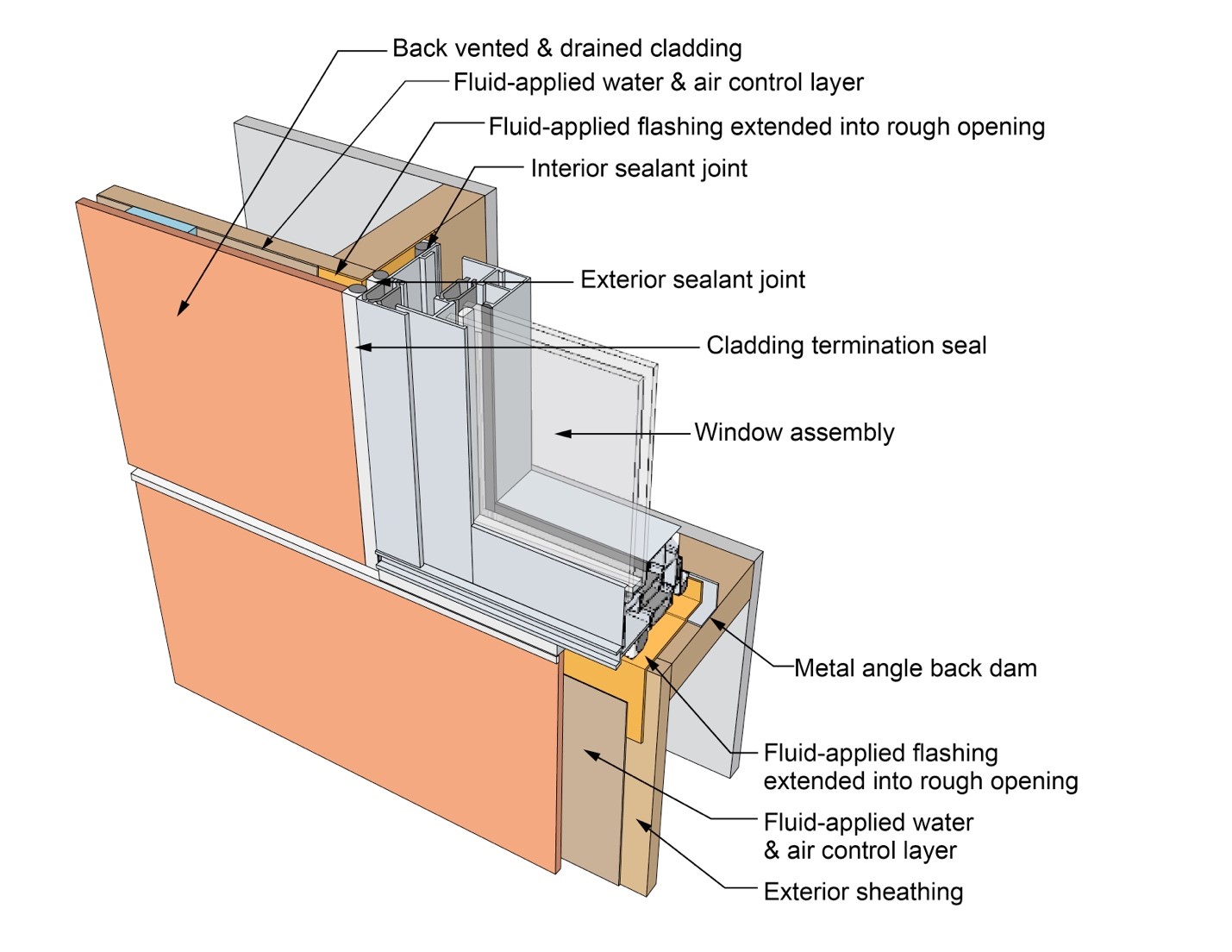
This drawing shows key jamb details for a window installation using a fluid-applied flashing on a wall with a fluid-applied water and air control layer
Image
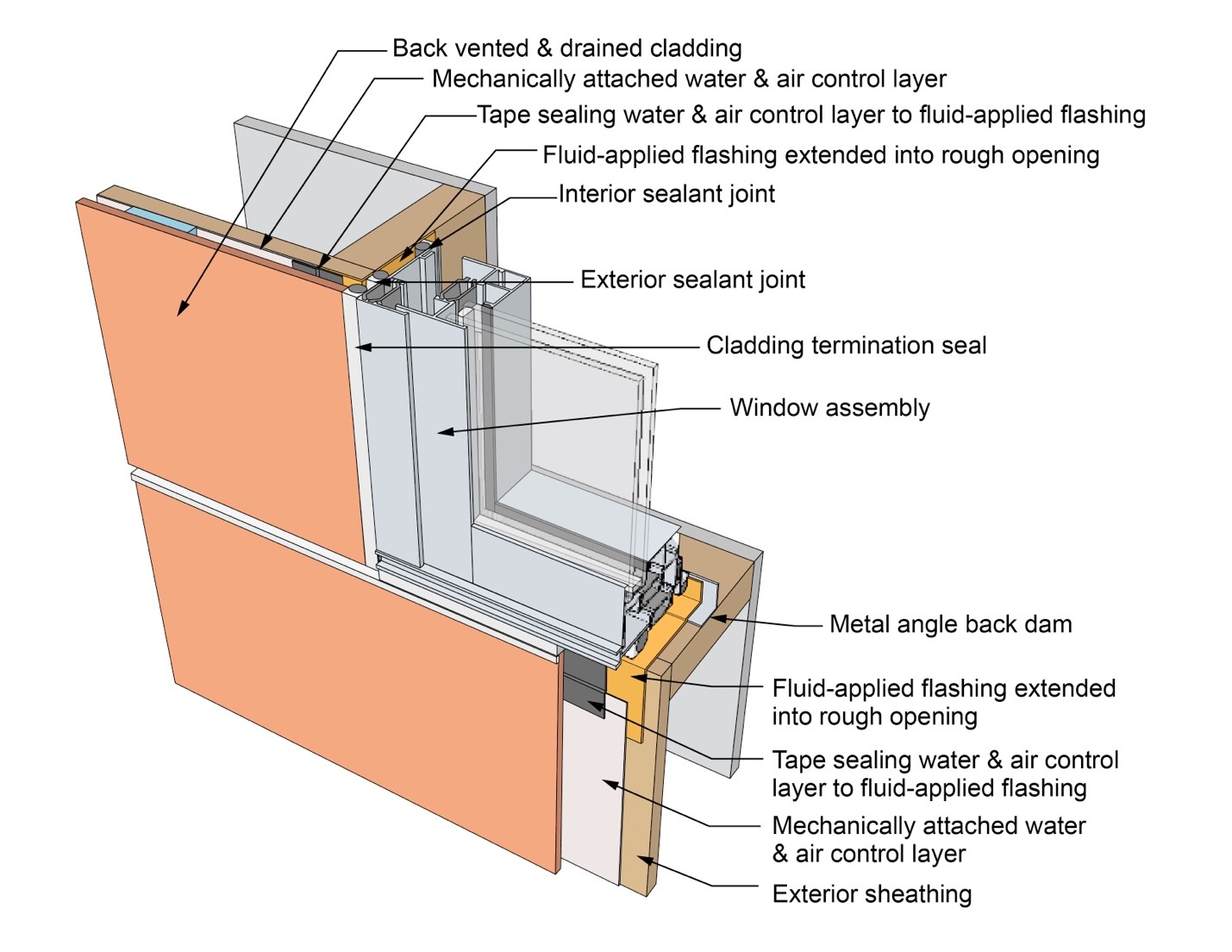
This drawing shows key jamb details for a window installation using a fluid-applied flashing on a wall with a mechanically attached water and air control layer
Image
This drawing shows key jamb details for a window installation using a fluid-applied flashing on a wall with a mechanically attached water and air control layer and continuous insulation
Image
This drawing shows key jamb details for a window installation using a self-adhered membrane tape flashing on a wall with a mechanically attached water and air control layer
Image
This drawing shows key jamb details for an “outie” window installation using a fluid-applied flashing on a wall with a fluid-applied water and air control layer and continuous insulation
Image
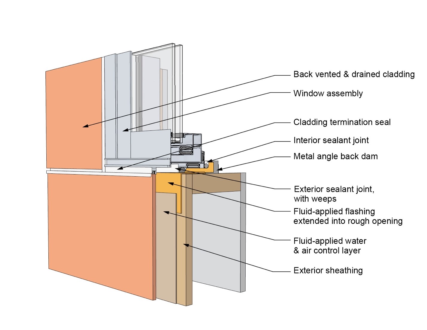
This drawing shows key sill details for a window installation using a fluid-applied flashing on a wall with a fluid-applied water and air control layer
Image
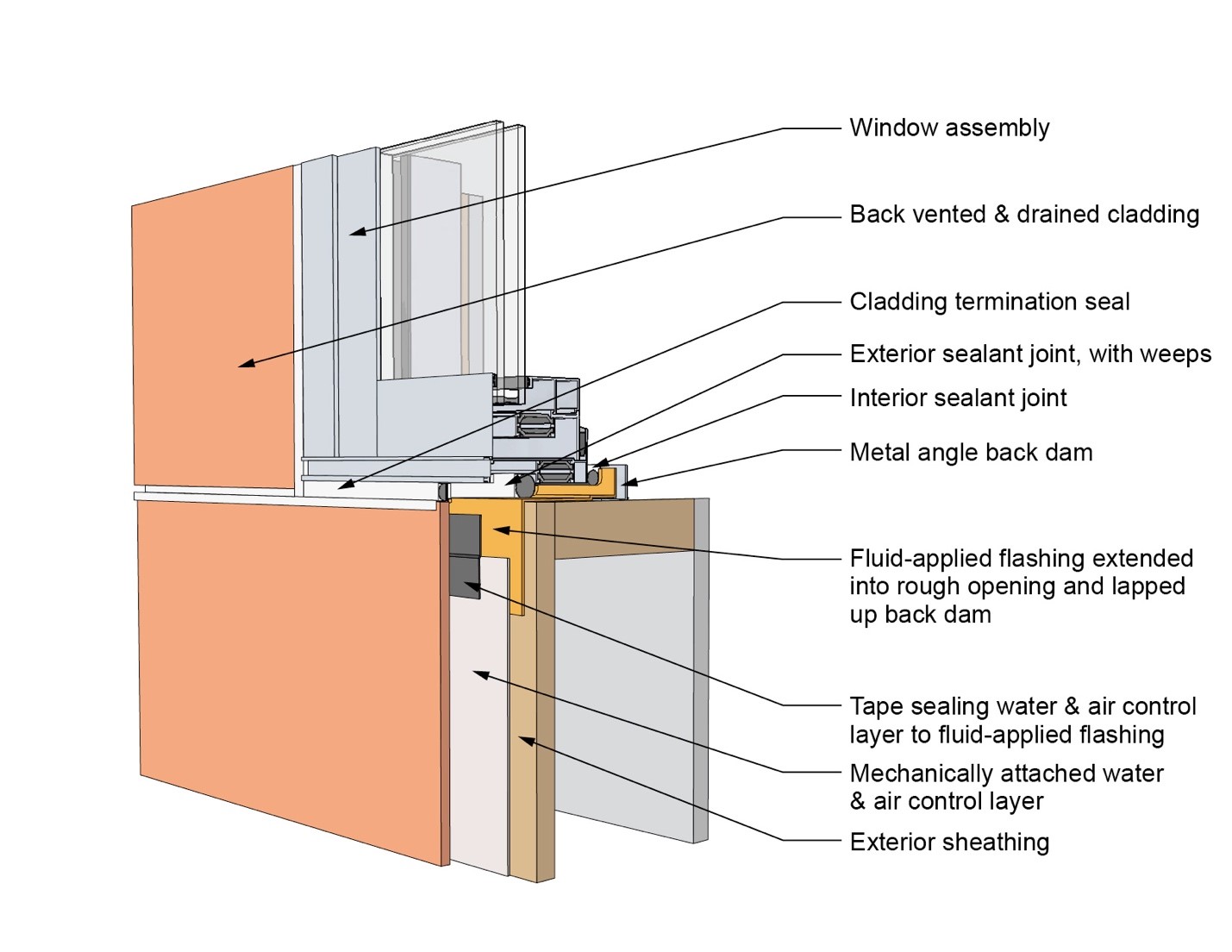
This drawing shows key sill details for a window installation using a fluid-applied flashing on a wall with a mechanically attached water and air control layer
Image
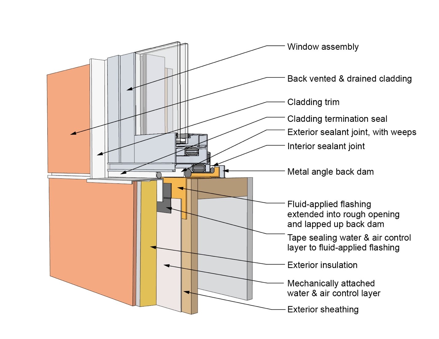
This drawing shows key sill details for a window installation using a fluid-applied flashing on a wall with a mechanically attached water and air control layer and continuous insulation
Image
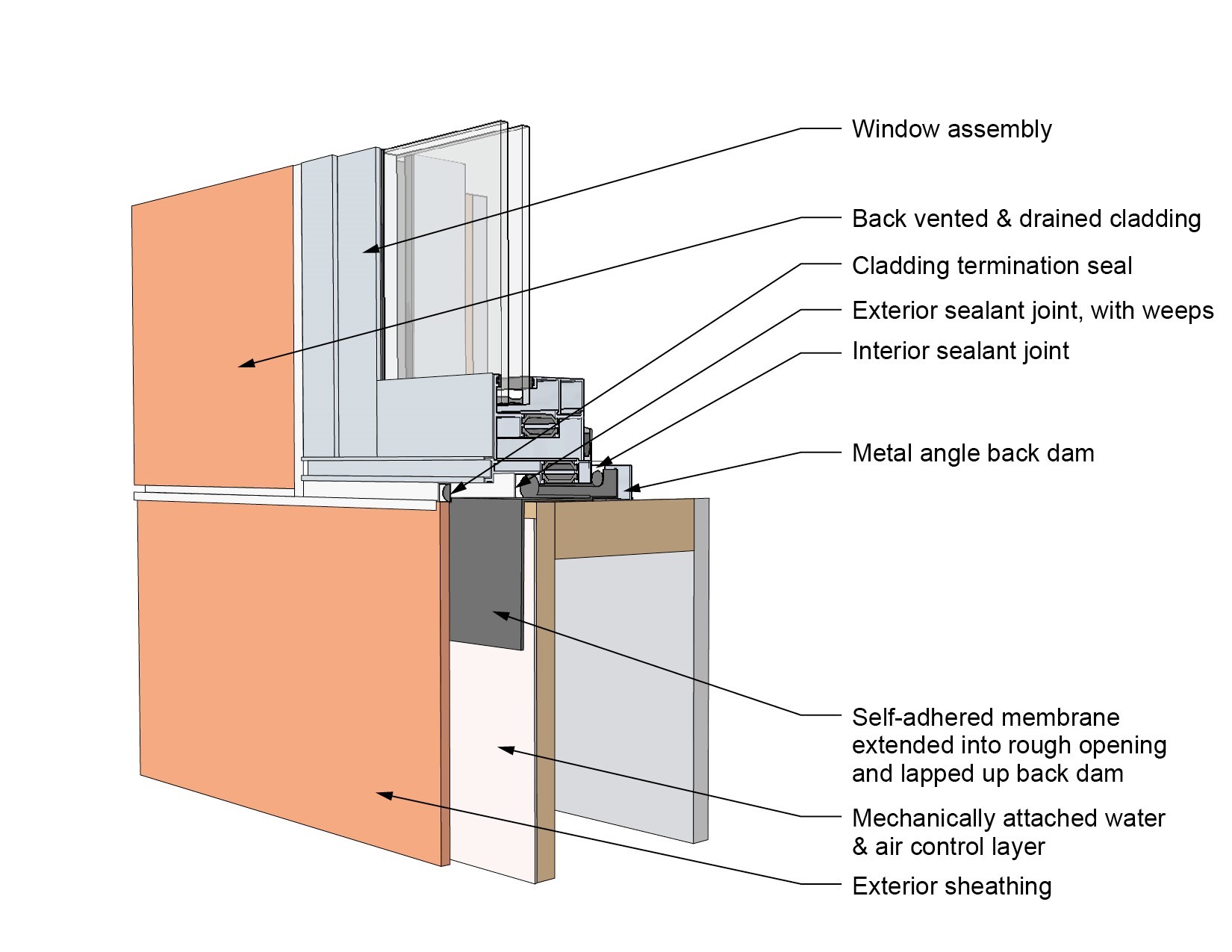
This drawing shows key sill details for a window installation using a self-adhered membrane tape flashing on a wall with a mechanically attached water and air control layer
Image
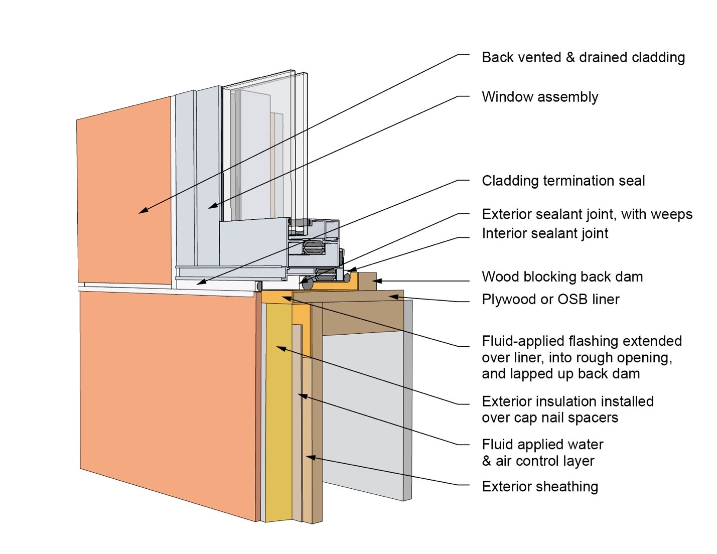
This drawing shows key sill details for an “outie” window installation using a fluid-applied flashing on a wall with a fluid-applied water and air control layer and continuous insulation
Image
Image
Windows are installed as “outies” in this wall assembly using a self-adhered membrane water and air control layer with continuous exterior insulation
Image
Image

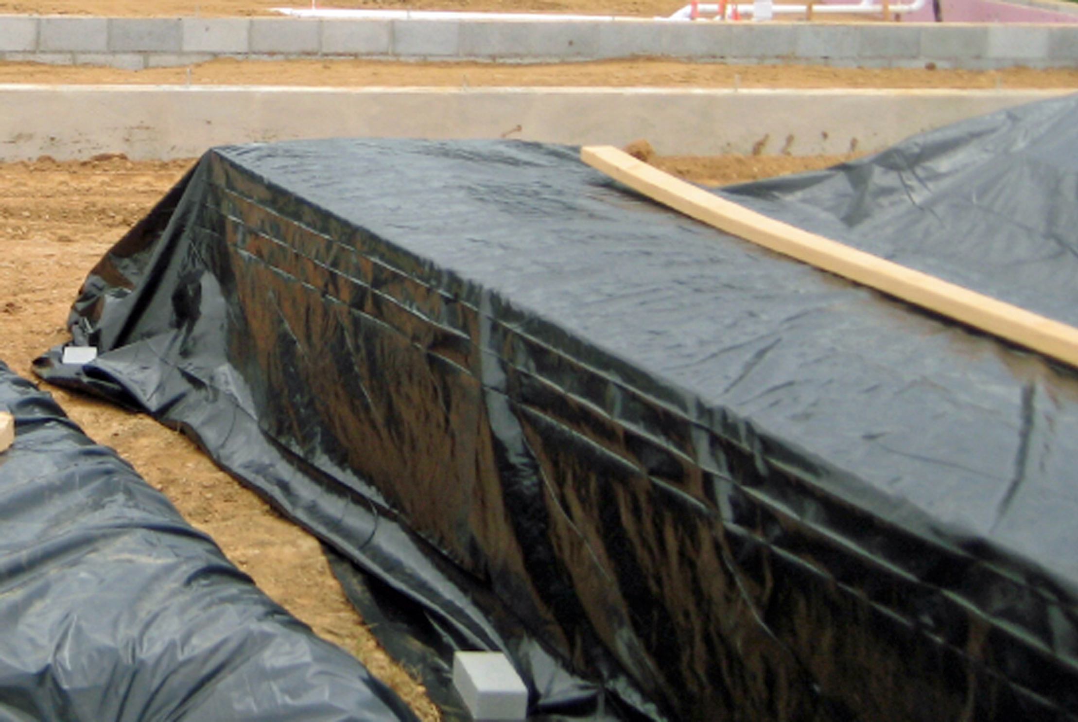
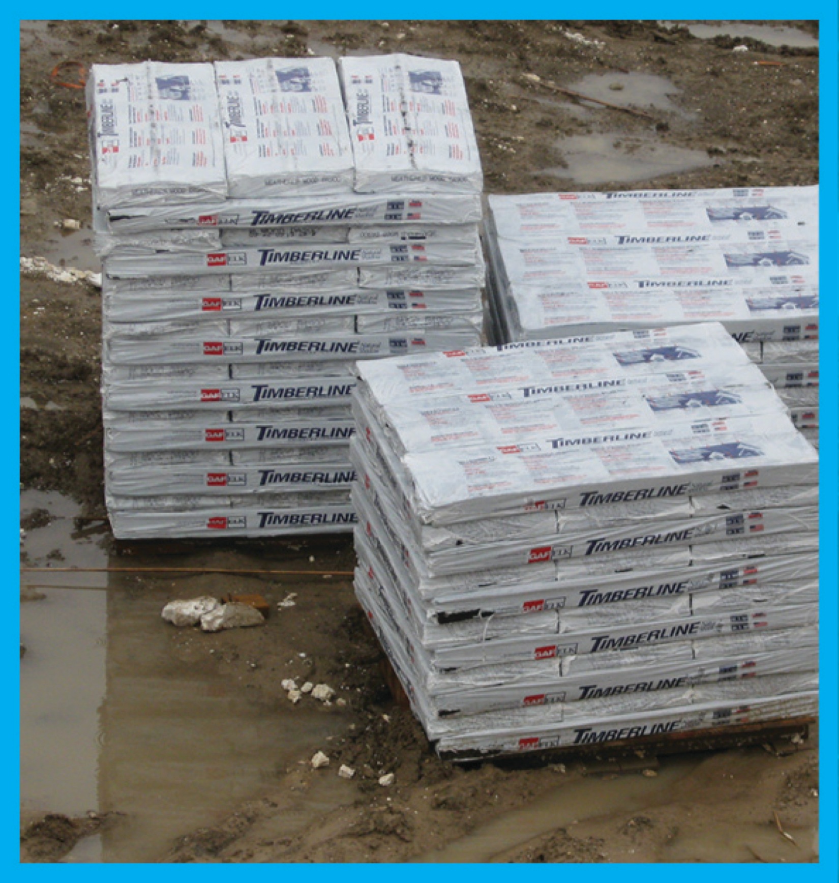
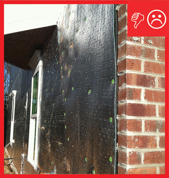
Wrong – Building materials are being stored outdoors with no protection from weather