Drawings
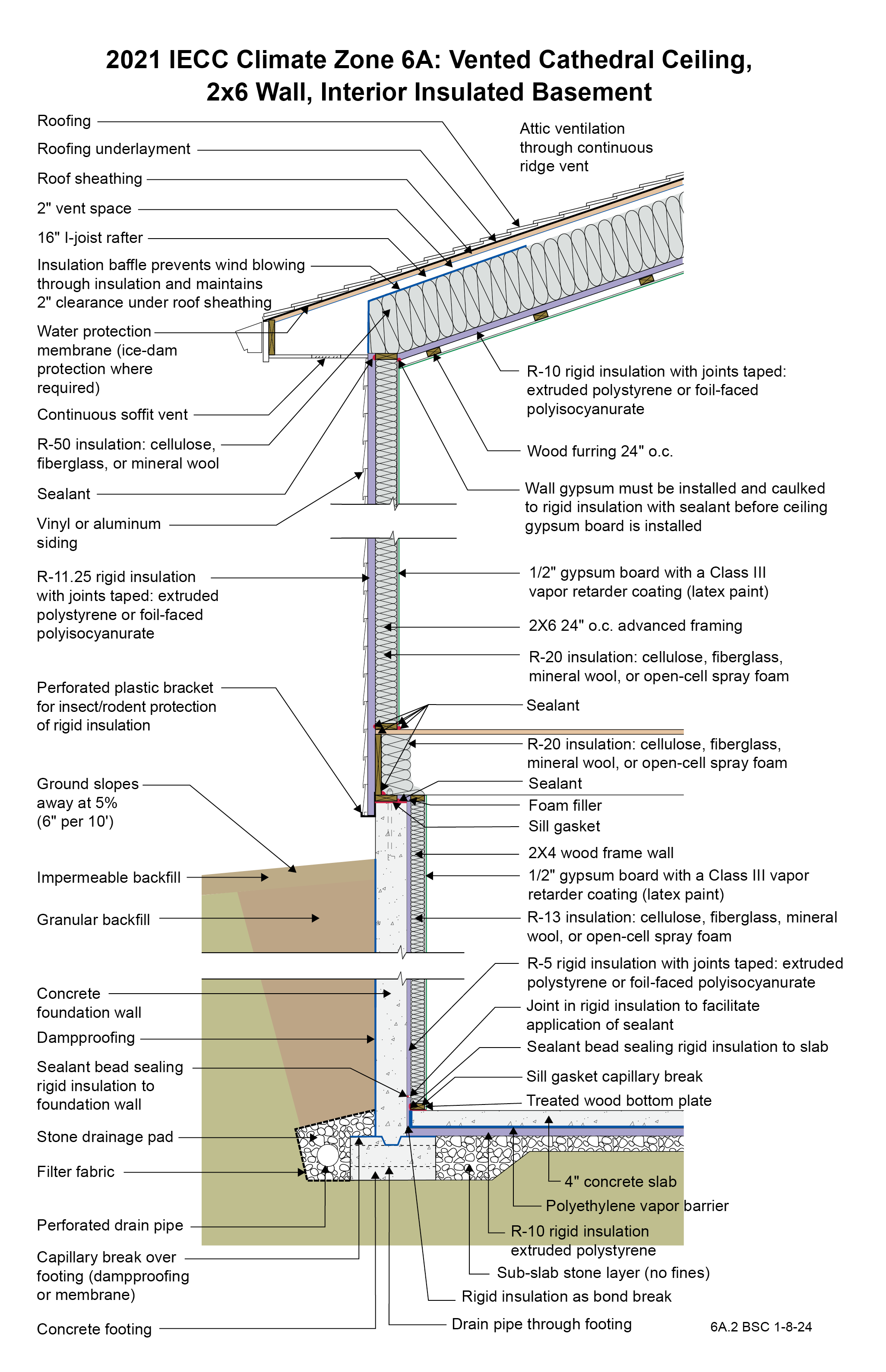
2021 IECC Climate Zone 6A: Vented Cathedral Ceiling, 2x6 Wall, Interior Insulated Basement
Notes
Drawing 6A.2: IECC CZ 6: Vented Cathedral Ceiling, 2x6 Wall, Interior Insulated Basement
- The R-10 rigid foam at the ceiling is not required for vapor control purposes in Climate Zone 6 as long as sufficient ridge- and soffit-venting is provided. However, it will aid the control of moisture by slowing vapor transfer from the conditioned space to the roof assembly. The rigid foam brings the total roof R-value up to the 2021 IECC requirement of R-60. Because the I-joist rafter is 16 inches and a 2-inch ventilation space is needed above the insulation, only about 14 inches are available for the fibrous cavity insulation. This will typically give an R-value of about R-50, leaving the need for the R-10 rigid foam. Note that only 1 inch of ventilation space above the cavity insulation is required by code, but 2 inches is recommended in areas where ice damming could be an issue or where rafter spans are long. The rigid foam at the ceiling is also used to allow the creation of a service raceway between the rigid foam and the gypsum board below it. The rigid foam acts as the air control layer instead of the gypsum board. The service raceway allows the air control layer to be undisturbed by the electrical penetrations in the ceiling. A third purpose of the rigid foam in this application is that it also reduces drywall cracking. From a vapor control standpoint, however, the rigid foam and the raceway are not required by 2021 IRC, and R-60 fibrous cavity insulation could be installed directly on top of the gypsum board if cavity height allows and if the attic is properly ventilated. In this case the gypsum board would become the air control layer and would need to be carefully sealed, and a Class I or II vapor retarder paint would be recommended at the ceiling.
- A low-permeance roofing underlayment (less than 1 perm) is recommended for this roof type in this climate to reduce water diffusion through the underlayment to the sheathing.
- The wall is framed with 2x6 24” o.c. advanced framing as it uses less board footage (volume of wood framing) than standard 2x4 16” o.c. framing and has therefore been shown to be less expensive in material cost. It has also been proven to be less expensive in labor (25% fewer framing members) and is faster to assemble. This must be balanced with the difference in insulation costs for the two framing approaches.
- With an R-20 2x6 wall, the rigid foam on the outside of the wall must be at least R-11.25 per the 2021 IRC Table 702.7(3) to control condensation within the framing cavities. There is no interior vapor barrier– there is a vapor “retarder” (Class III vapor retarder – semi-permeable latex paint). The reason that there is no interior vapor barrier is to permit drying to the interior.
- An alternative to this wall assembly that meets both thermal and vapor control requirements is to use an R-13 2x4 wall with R-10 rigid foam on the outside.
- The rigid foam on the exterior of the wall allows construction without using structural sheathing: alternative methods of wall bracing are used instead, and the rigid foam provides a backstop for the cavity insulation as well as some structural support to the siding. Many contractors have found this to be a more economical approach.
- The plastic L-bracket at the bottom of the wall’s exterior rigid insulation should be perforated to facilitate drainage.
- The R-5 rigid insulation on the interior of the concrete foundation wall is required to control condensation within the interior frame wall as there is no interior vapor barrier on the interior of the frame wall – there is a Class III vapor “retarder” (semi-permeable latex paint). The reason that there is no interior vapor barrier on the interior of the frame wall is to permit drying to the interior. Additionally, the R-5 rigid insulation on the interior of the concrete foundation wall reduces the rate at which moisture contained in newly placed concrete moves to the interior.
- The vertical “short” strip of rigid insulation where the basement concrete slab intersects the exterior concrete basement wall has two lines of continuous sealant. The first seals the concrete slab edge to the interior surface of the vertical strip. The second seals the top back corner of the vertical strip to the concrete foundation wall. The two seals provide air control layer continuity between the concrete slab and the concrete wall to control radon and other soil gases.
- Horizontal insulation on the underside of the concrete floor slab is provided for comfort reasons and to control dust mites in carpets by reducing the relative humidity within the carpets.
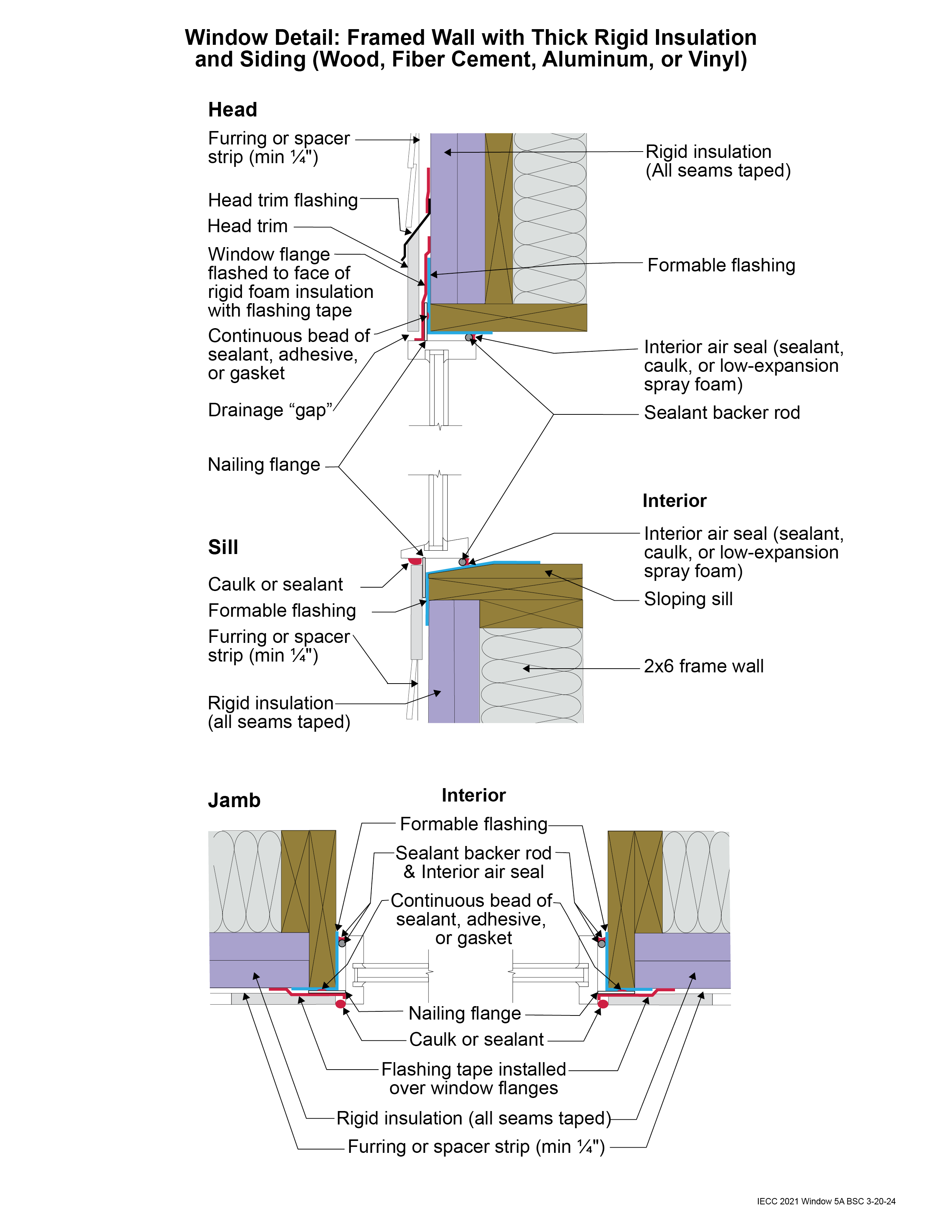
2021 IECC Window Detail: Framed Wall with Thick Rigid Insulation and Siding (Wood, Fiber Cement, Aluminum or Vinyl)
Notes
Window Detail 5A - Framed Wall with Thick Rigid Insulation and Siding (Wood, Fiber Cement, Aluminum or Vinyl)
- Note: Always follow the window manufacturer’s installation guidance. Not following manufacturer guidance may void the warranty.
- This is a “drained wall”. The exterior face of the rigid insulation is carefully taped at all seams, allowing it to act as the water control layer. Drainage occurs between the siding and the exterior face of the rigid insulation. A drainage gap is provided by furring installed vertically over the exterior face of the rigid insulation at stud locations.
- The window openings are drained to the exterior face of the rigid foam since it is acting as the water control layer.
- The rough opening at the windowsill is sloped and flashed to the rigid foam with a formable flashing.
- The upper portion of the head trim flashing goes under the furring and is taped directly to the rigid foam with flashing tape. The furring is “cut through” by the head trim flashing, so that the furring below the flashing (behind the head trim) is separate from the furring above the flashing (behind the siding). During construction the head trim is installed first on short pieces of furring. It is flashed directly to the rigid foam as described above. The rest of the furring is installed with the siding.
- With thick rigid foam installed on the exterior, providing nailing surfaces for trim and siding can be a challenge. Furring strips are one approach to accomplish this. Some form of structural wood may be needed around the windows to accommodate trim. There are many ways to accomplish this. In the assembly shown, wide lumber is used to create the rough opening, allowing nail-able wood to extend to the exterior surface of the rigid foam but also creating a thermal bridge.
- A formable membrane connects the rigid foam to the wood frame. It should extend inwards at least past the point where the interior air seal is located around all sides of the window frame. This creates water-resistant surfaces inside the cavity between the window flanges and the interior air seal, in case any water gets behind the flanges. The head and jamb window flanges are flashed to the rigid foam using a self-adhered flashing membrane or flashing tape. The sill window flange is not flashed, to allow any water that may get behind the flanges to escape.
- This assembly relies heavily on the use of proper tapes, flashings, and membranes that will adhere securely and durably to the rigid foam. Products should only be used if they have been well-established to be appropriate for this application.
- Note the gap between the head trim and the top of the window assembly frame. This gap allows water to drain and allows the bottom of the trim to dry out more easily. If installed without this gap, capillary action can draw water into the tight space between the head trim and the window assembly frame. Note also the gap between the siding and the head trim flashing, which serves the same purposes.
- Consider installing rigid head flashing (rigid head flashing is not shown in the schematic). Rigid head flashing is similar to the head trim flashing shown in the schematic, but it goes over the top of the window frame instead of over the head trim. This is required by some manufacturers. It should be installed against the head nailing flange and over the top of the window frame. The vertical and horizontal portion of the flashing should be sealed directly to the window frame and flange with sealant. The red flashing membrane strip shown overlapping the head nailing flange in the schematic would now overlap the rigid head flashing. Use rigid head flashing with a drip edge to guide water away from the window assembly.
- Backer rod for the interior air sealant should be installed after the window is installed, leveled, and shimmed. Use the correct size backer rod.
2021 IECC Window Detail: Framed Wall with Rigid Insulation and Siding (Wood, Fiber Cement, Aluminum or Vinyl)
Notes
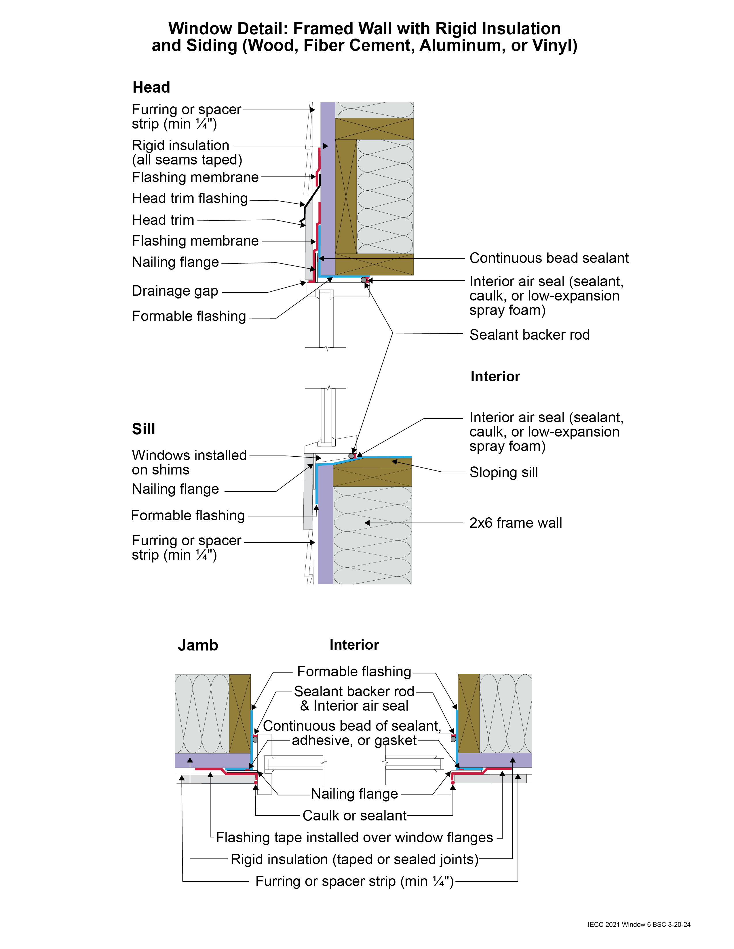
Window Detail 6 - Framed Wall with Rigid Insulation and Siding (Wood, Fiber Cement, Aluminum or Vinyl)
- Note: Always follow the window manufacturer’s installation guidance. Not following manufacturer guidance may void the warranty.
- This is a “drained wall”. The exterior face of the rigid insulation is carefully taped at all seams, allowing it to act as the water control layer. Drainage occurs between the siding and the exterior face of the rigid insulation. A drainage gap is provided by furring installed vertically over the exterior face of the rigid insulation at stud locations.
- The window openings are drained to the exterior face of the rigid foam since it is acting as the water control layer.
- The rough opening at the windowsill is sloped and flashed to the rigid foam with a formable flashing.
- The upper portion of the head trim flashing goes under the furring and is taped directly to the rigid foam with flashing tape. The furring is “cut through” by the head trim flashing, so that the furring below the flashing (behind the head trim) is separate from the furring above the flashing (behind the siding). During construction, the head trim is installed first on short pieces of furring. It is flashed directly to the rigid foam as described above. The rest of the furring is installed with the siding.
- A formable flashing membrane connects the rigid foam to the wood frame. It should extend inwards at least past the point where the interior air seal is located around all sides of the window frame. This creates water-resistant surfaces inside the cavity between the window flanges and the interior air seal, in case any water gets behind the flanges. The head and jamb window flanges are flashed to the rigid foam using a self-adhered flashing membrane. The sill window flange is not flashed, to allow any water that may get behind the flanges to escape.
- This assembly relies heavily on the use of proper tapes, flashings, and membranes that will adhere securely and durably to the rigid foam. Products should only be used if they have been well-established to be appropriate for this application.
- Note the gap between the head trim and the top of the window assembly frame. This gap allows water to drain and allows the bottom of the trim to dry out more easily. If installed without this gap, capillary action can draw water into the tight space between the head trim and the window assembly frame. Note also the gap between the siding and the head trim flashing, which serves the same purposes.
- Consider installing rigid head flashing (rigid head flashing is not shown in the schematic). Rigid head flashing is similar to the head trim flashing shown in the schematic, but it goes over the top of the window frame instead of over the head trim. This is required by some manufacturers. It should be installed against the head nailing flange and over the top of the window frame. The vertical and horizontal portion of the flashing should be sealed directly to the window frame and flange with sealant. The red flashing membrane strip shown overlapping the head nailing flange in the schematic would now overlap the rigid head flashing. Use rigid head flashing with a drip edge to guide water away from the window assembly.
- Backer rod for the interior air sealant should be installed after the window is installed, leveled, and shimmed. Use the correct size backer rod.