Drawings
2021 IECC Climate Zone 6A: Vented Attic, Exterior Double Wall, Interior Insulated Basement
Notes
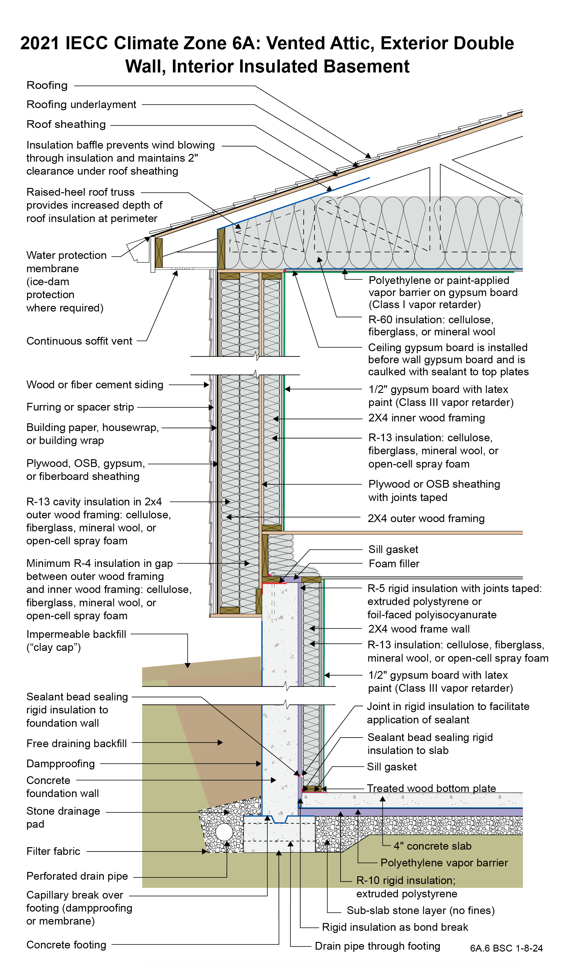
Drawing 6A.6: IECC CZ 6: Vented Attic, Exterior Double Wall, Interior Insulated Basement
- The function of the raised-heel roof truss is to control the temperature of the interior corner where the exterior wall meets the ceiling to control dust marking and mold. The minimum thermal resistance over the top of the wall assembly should match or exceed the thermal resistance of the wall assembly. Increasing the height of the raised heel can allow lower attic insulation levels by code. Per IECC 2021 Section R402.2.1, Ceilings with Attics, the ceiling insulation of this assembly can be R-49 rather than R-60 if the raised-heel roof truss is high enough to facilitate R-49 over the entire wall.
- A low-permeance roofing underlayment (less than 1 perm) is recommended for this roof type in this climate to reduce water diffusion through the underlayment to the sheathing.
- The ceiling gypsum board is installed prior to the wall gypsum board in order to accommodate a “filet” bead of sealant that seals the ceiling gypsum board to the top plates creating a continuous air control layer (“air barrier”) across the entire ceiling including interior partition walls. The gypsum board is the air control layer. The polyethylene at the ceiling is the vapor control layer.
- The OSB or plywood plate at the top of the double wall is an effective airstop and therefore acts as a firestop. Some jurisdictions may require this to be supplemented (not replaced) by a wood block or rigid mineral wool.
- The outer portion of the exterior wall of the double-wall assembly is attached to the underside of the roof truss – it is “hung” from the truss. Exterior double-wall assemblies do not require giving up interior floor area compared to interior double-wall assemblies. They also reduce basement concrete perimeter wall area. The gap between the outer wall framing and the inner wall framing can be increased to accommodate more insulation. The taped plywood or OSB sheathing on the exterior of the inner wall framing is the assembly air control layer and vapor control layer.
- Depending on interpretation, this assembly may not meet the 2021 IRC prescriptive requirements for vapor control. However, the assembly meets the intent of the code by keeping the first condensing surface above condensing temperatures. The first condensing surface within this assembly is the interior surface of the taped sheathing. More than half of the insulation in the assembly is to the outside of this surface, which helps it stay above condensing temperatures. The insulation on the outside of the taped sheathing serves a similar purpose to the continuous insulation requirements in 2021 IRC Table R702.7(3).
- The R-5 rigid insulation on the interior of the concrete foundation wall is required to control condensation within the interior frame wall as there is no interior vapor barrier on the interior of the frame wall – there is a Class III vapor “retarder” (semi-permeable latex paint). The reason that there is no interior vapor barrier on the interior of the frame wall is to permit drying to the interior. Additionally, the R-5 rigid insulation on the interior of the concrete foundation wall reduces the rate at which moisture contained in newly placed concrete moves to the interior.
- The vertical “short” strip of rigid insulation where the basement concrete slab intersects the exterior concrete basement wall has two lines of continuous sealant. The first seals the concrete slab edge to the interior surface of the vertical strip. The second seals the top back corner of the vertical strip to the concrete foundation wall. The two seals provide air control layer continuity between the concrete slab and the concrete wall to control radon and other soil gases.
- Horizontal insulation on the underside of the concrete floor slab is provided for comfort reasons and to control dust mites in carpets by reducing the relative humidity within the carpets.
2021 IECC Window Detail: Framed Wall with Plywood or OSB Sheathing, a WRB, and Siding (Wood, Fiber Cement, Aluminum or Vinyl, or Stucco)
Notes
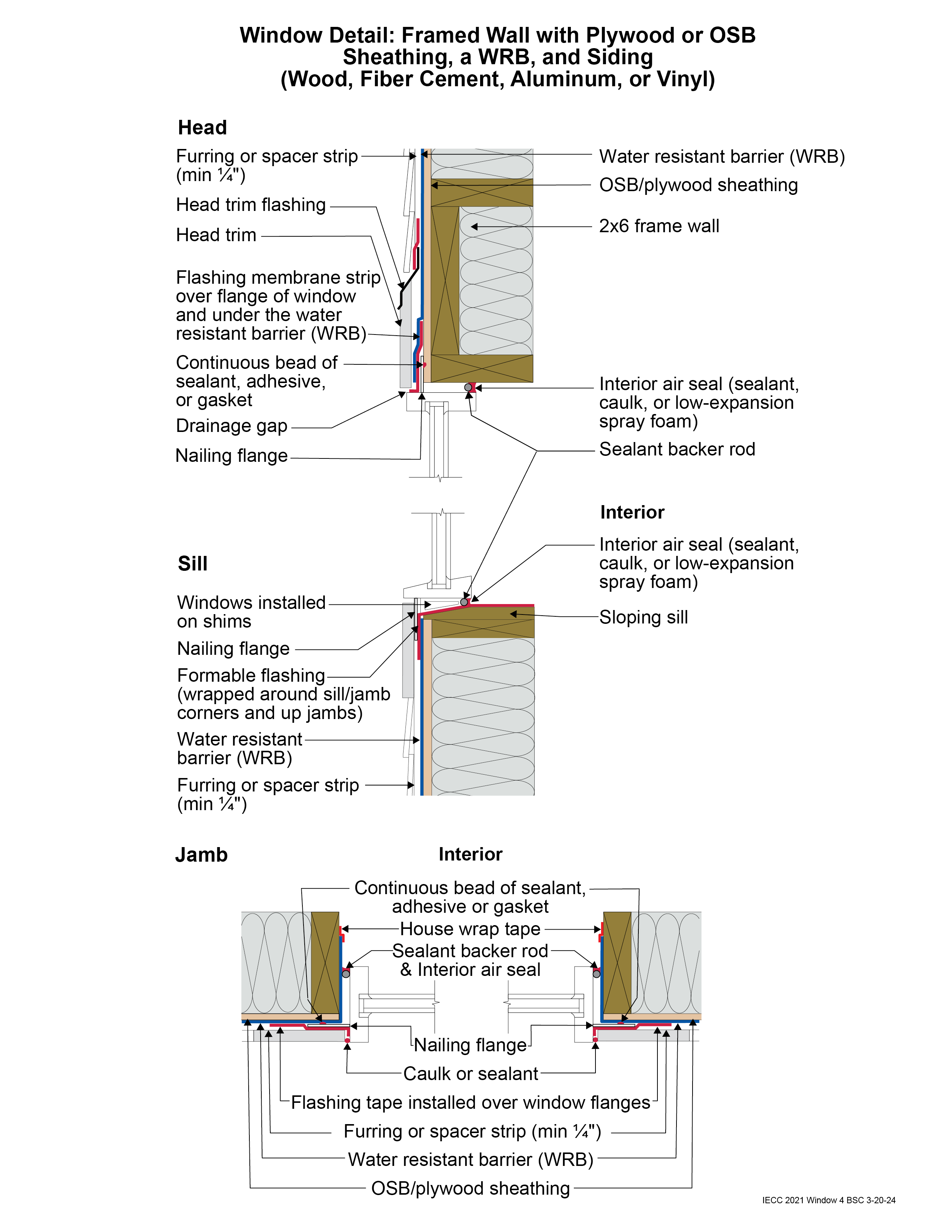
Window Detail 4 - Framed Wall with Plywood or OSB Sheathing, a WRB, and Siding (Wood, Fiber Cement, Aluminum or Vinyl, or Stucco)
- Note: Always follow the window manufacturer’s installation guidance. Not following manufacturer guidance may void the warranty.
- This is a “drained wall”. Drainage occurs between the siding and the water control layer or water resistant barrier (WRB) in the gap created by furring which is installed vertically over the water control layer (WRB) at stud locations. In the case of a stucco wall, the drainage plane is a drainage mat rather than furring gaps.
- The window openings are drained to the water control layer (WRB).
- The rough opening at the window sill is sloped and flashed with a formable flashing.
- The upper portion of the head trim flashing goes under the furring and is taped directly to the WRB with flashing tape. The furring is “cut through” by the head trim flashing, so that the furring below the flashing (behind the head trim) is separate from the furring above the flashing (behind the siding). During construction, the head trim is installed first on short strips of furring. It is flashed directly to the WRB as described above. The rest of the furring is installed with the siding. In the case of a stucco wall, the drainage mat would be treated in similar fashion to furring: the head trim flashing would go under the drainage mat and be taped directly to the WRB with flashing tape.
- Note the gap between the head trim and the top of the window assembly frame. This gap allows water to drain and allows the bottom of the trim to dry out more easily. If installed without this gap, capillary action can draw water into the tight space between the head trim and the window assembly frame. Note also the gap between the siding and the head trim flashing, which serves the same purposes.
- Consider installing rigid head flashing (rigid head flashing is not shown in the schematic). Rigid head flashing is similar to the head trim flashing shown in the schematic, but it goes over the top of the window frame instead of over the head trim. This is required by some manufacturers. It should be installed against the head nailing flange and over the top of the window frame. The vertical and horizontal portion of the flashing should be sealed directly to the window frame and flange with sealant. The red flashing membrane strip shown overlapping the head nailing flange in the schematic would now overlap the rigid head flashing. Use rigid head flashing with a drip edge to guide water away from the window assembly.
- Backer rod for the interior air sealant should be installed after the window is installed, leveled, and shimmed. Use the correct size backer rod.