



Scope

Install high-performance windows for multifamily buildings.
- Select the appropriate window performance grade for the project (Residential Windows (R), Light Commercial Windows (LC), Architectural Windows (AW), or Commercial Windows (CW)).
- Select high-performance windows meeting ENERGY STAR criteria or better.
- Install windows using careful flashing and sealing details to ensure continuity of water, air, vapor, and thermal control layers from the wall to the window.
- Adjust installation details and approaches based on wall type.
See the Compliance Tab for links to related codes and standards and voluntary federal energy-efficiency program requirements.
Description
The Fenestration and Glazing Industry Alliance (FGIA) defines four window type classifications: Residential Windows (R), Light Commercial Windows (LC), Architectural Windows (AW), and Commercial Windows (CW). The specifications for each window type are found in Table 1 (FGIA 2024).
Table 1. The 2022 North American Fenestration Standard/Specification for windows, doors, and skylights defines minimum performance requirements for each of the four window performance classes; performance is progressively more stringent from Class R to Class AW (Source: FGIA 2024).
| Performance Class | Maximum Allowable Air Leakage CFM/ft2 at psf | Minimum Water Test Pressure psf | Required Minimum Percentage of Design Pressure for Water Test |
| R | 0.30 at 1.57 | 2.92 | 15% |
| LC | 0.30 at 1.57 | 3.76 | 15% |
| CW | 0.30 at 1.57 | 4.59 | 15% |
| AW | 0.10 at 6.24 | 8.15 | 20% |
Residential Windows (R) are used in one- and two-story residential buildings including town houses and row houses that typically experience low wind loading.
Light Commercial Windows (LC) are typically used in low-rise and mid-rise buildings where larger window sizes and higher wind loading requirements are expected.
Commercial Windows (CW) are used in low-rise and mid-rise buildings where larger window sizes and high wind loading are expected, and limits on deflection are required.
Architectural Windows (AW) are used in high-rise buildings and mid-rise buildings where high wind loading requirements are expected and limits on deflection are required. Architectural Windows (AW) are typically tested/rated at higher air pressures in determining acceptable allowable air leakage and water leakage as compared to Commercial Windows (CW).
Multifamily buildings typically are constructed with Commercial Windows (CW) and Architectural Windows (AW). Although the different window classes are tested and rated at different air pressures, they are installed in similar manners in wall assemblies. There is no practical difference in the water management and air management installation approaches to the classes of windows. However, window installation approaches have to be tailored to specific wall types. A variety of wall assemblies are used in multifamily buildings, with varying use of fluid-applied water and air control layers, mechanically attached water and air control layers, self-adhered membrane liners, and continuous exterior insulation.
General Window Installation Concepts
Buildings are environmental separators. At a very basic level, design and construction of buildings can be prioritized as follows: after addressing fire safety and structure, the key issues are water management, air management, vapor management, and thermal management.
Beyond fire safety and structural aspects, all wall assemblies require the following in order of importance:
- water control layer
- air control layer
- vapor control layer
- thermal control layer
Windows are essentially holes or penetrations in the wall. The window-to-wall connections need to address water control, air control, vapor control and thermal control, while not compromising structure or fire safety.
The general approach to incorporating windows into walls is as follows:
- Install the window to withstand wind loads and seismic motion.
- Connect the water control layer of the wall to the water control layer of the window.
- Connect the air control layer of the wall to the air control layer of the window.
- Connect the vapor control layer of the wall to the vapor control layer of the window.
- Connect the thermal control layer of the wall to the thermal control layer of the window.
There are many permutations and combinations of window unit materials, flashing materials, and sealant types that can be used in window installations (Figures 1 and 2). However, the fundamental approach of carefully connecting water, air, vapor, and thermal control layers applies to all installations. Manufacturer’s installation instructions should always be followed, along with the details and specifications of the architect of record. The architect of record’s details and specifications have precedence over all other details and specifications.
Source
Source
Example Window Installation Details
The examples below provide details intended to follow the principles outlined above. Note that sloped sills are recommended best practice, but are often not used in the field. All of the details below could be improved by incorporating sloped sills to guide water outwards to the water control layer.
Example 1: Fluid-Applied Water and Air Control Layer Coupled with a Fluid-Applied Flashing
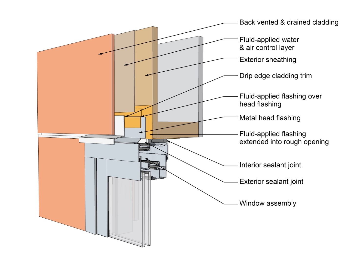
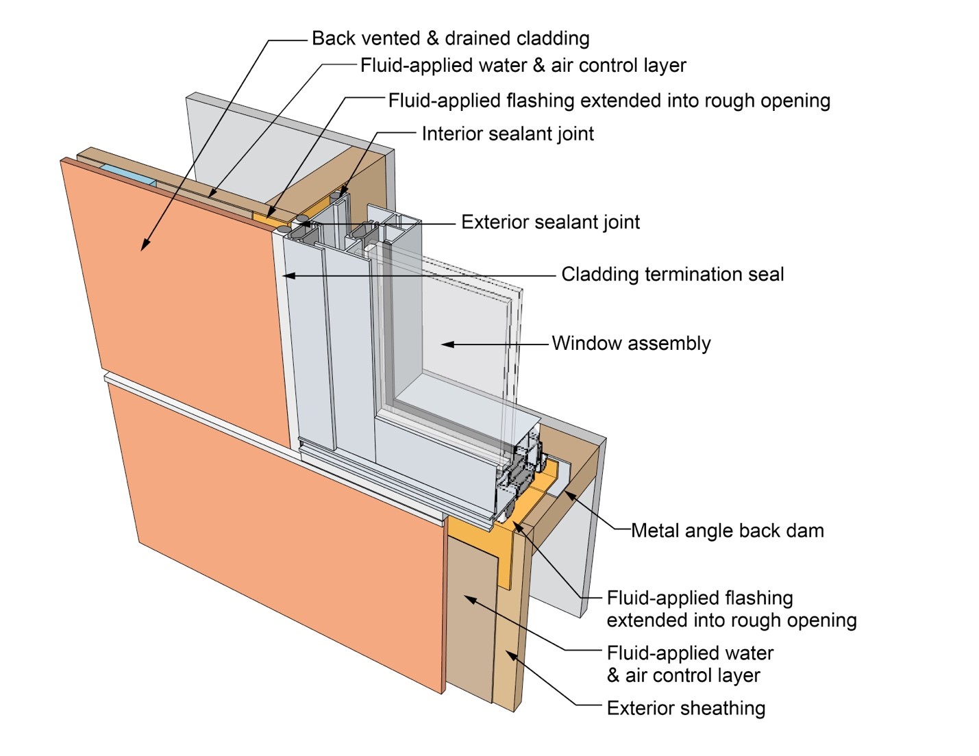
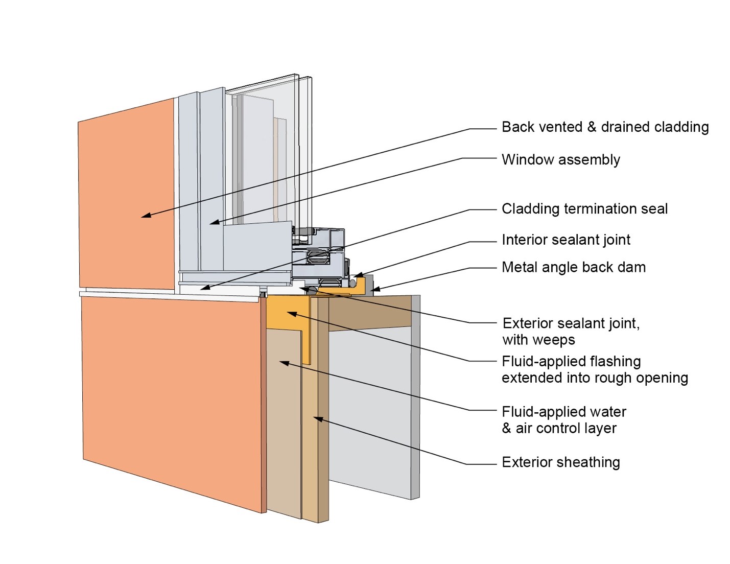
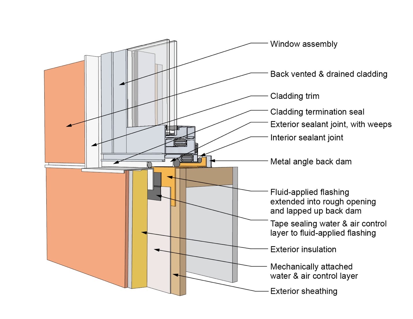
Figures 3, 4 and 5 illustrate the details for this example installation. Note the following key aspects of the installation:
- A fluid-applied flashing membrane is used to line the entire perimeter of the rough opening before the window is installed. The fluid-applied flashing membrane extends from the interior of the rough opening framing to the exterior face of the exterior sheathing. It wraps around the exterior opening edge and extends 4 to 6 inches over the face of the exterior sheathing.
- A fluid seal is installed over the metal head flashing (Figure 3). The fluid seal could be replaced with a membrane flashing tape.
- Note the exterior and interior sealant joints. Do not confuse the exterior sealant joint with the “cladding termination seal,” sometimes called a “beauty bead” (shown in Figures 4 and 5). The primary function of the cladding termination seal is aesthetic, while the function of the exterior sealant joint is water control. Also note that the exterior sealant joint is weeped with weep tubes at the bottom of the window opening (Figure 5).
- Note the metal back dam in Figures 4 and 5. The back dam should be connected to the fluid-applied flashing membrane as shown. Some installers use a thick bead of sealant on the sill instead of a metal back dam. The recommended approach is to use a metal back dam and to connect the sill flashing to the back dam.
- It is common to provide a “drip edge cladding trim” at the head of the window opening (Figure 3). This does not take the place of the metal head flashing. The head flashing is critical, while the drip edge is not. The drip edge cladding trim reduces staining on the window unit from water running down the face of the cladding. The drip edge cladding trim is often reverse lapped due to construction sequencing – this does not affect the water management as its primary function is to provide a drip edge for the face of the cladding, not to drain the wall cavity.
- These details also work for a wall having a fully adhered water and air control layer instead of a fluid-applied layer.
Source
Source
Source
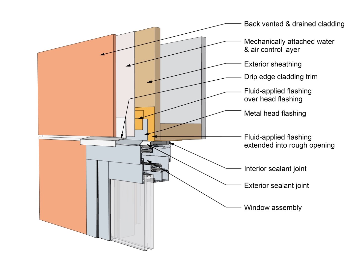
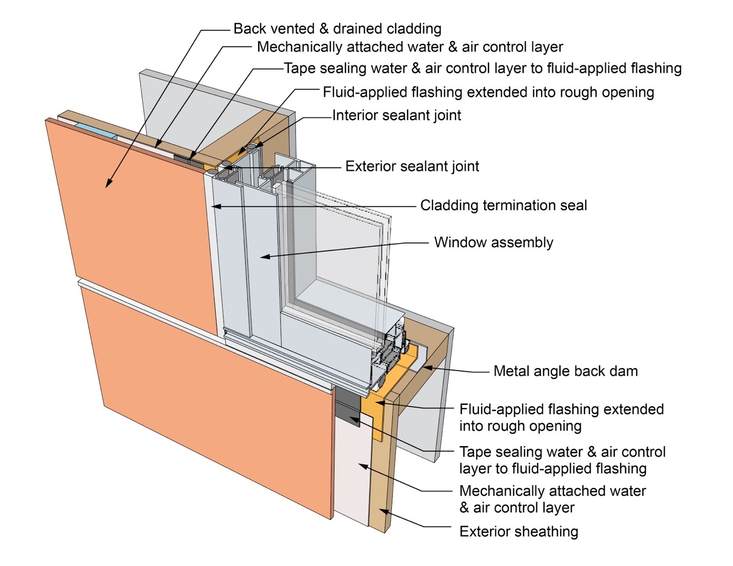
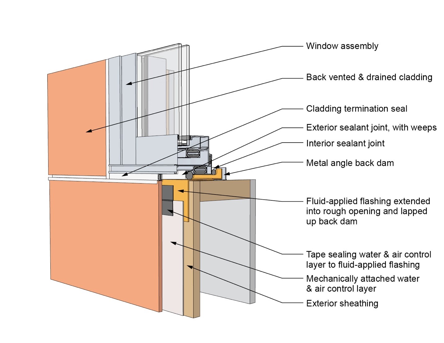
Example 2: Mechanically Attached Water and Air Control Layer Coupled with a Fluid-Applied Flashing
Mechanically attached water and air control layers are typically building papers, building wraps and house wraps. They are sometimes referred to as water or weather resistant barriers (WRB’s). Figures 6, 7 and 8 illustrate the details for this example installation. Note the following key aspects of the installation:
- A fluid-applied flashing membrane is used to line the entire perimeter of the rough opening before the window is installed. The fluid-applied flashing membrane extends from the interior of the rough opening framing to the exterior face of the exterior sheathing. It wraps around the exterior opening edge and extends 4 to 6 inches over the face of the exterior sheathing.
- A fluid seal is installed over the metal head flashing (Figure 6). The fluid seal could be replaced with a membrane flashing tape.
- The mechanically attached water and air control layer extends over the top of the head flashing and seal (Figure 6). This mechanically attached water and air control layer should not be sealed at its bottom edge at the head of the window to allow incidental water that penetrates the mechanically attached water and air control layer to drain out at the head.
- It is common to provide a “drip edge cladding trim” in addition to the metal head flashing (Figure 6). This does not take the place of the metal head flashing. The head flashing is critical, while the drip edge is not. The drip edge cladding trim reduces staining on the window unit from water running down the face of the cladding. The drip edge cladding trim is often reverse lapped due to construction sequencing – this does not affect the water management as its primary function is to provide a drip edge for the face of the cladding not to drain the wall cavity.
- Note the exterior and interior sealant joints. Do not confuse the exterior sealant joint with the “cladding termination seal,” sometimes called a “beauty bead” (shown in Figures 7 and 8). The primary function of the cladding termination seal is aesthetic, while the function of the exterior sealant joint is water control. Also note that the exterior sealant joint is weeped with weep tubes at the bottom of the window opening (Figure 8).
- Note the metal back dam in Figures 7 and 8. The back dam should be connected to the fluid-applied flashing membrane as shown. Some installers use a thick bead of sealant on the sill instead of a metal back dam. The recommended approach is to use a metal back dam and to connect the sill flashing to the back dam.
- Note the “shingling” of the taped mechanically attached water and air control layer at the sill.
Source
Source
Source
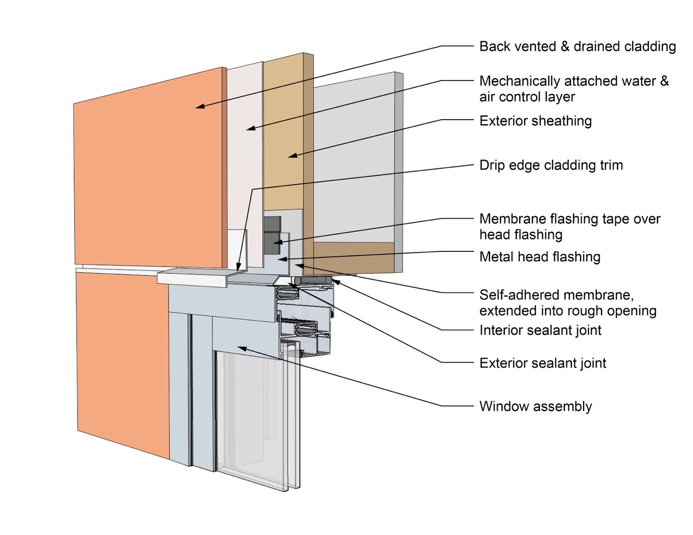
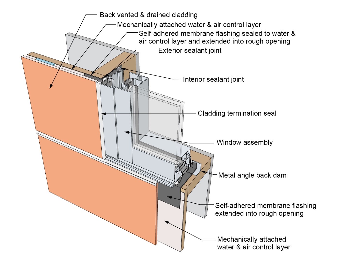
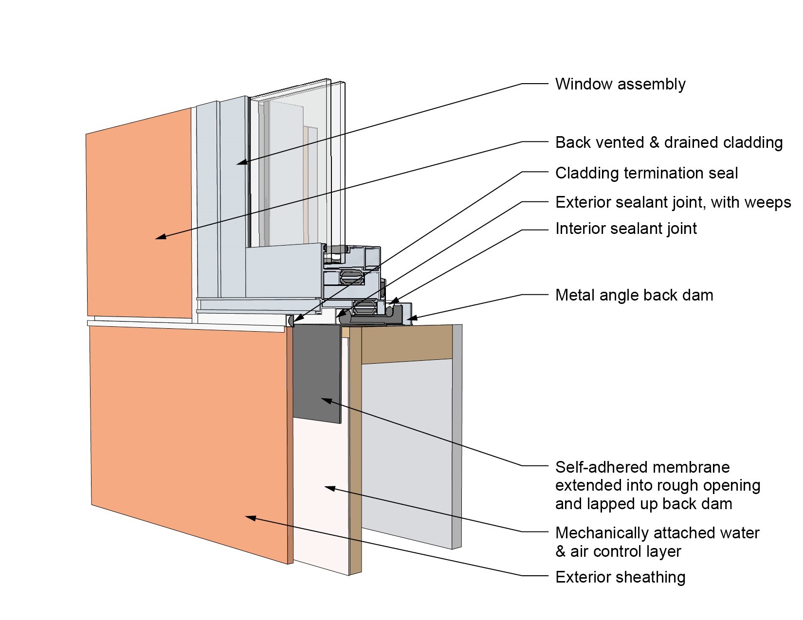
Example 3: Mechanically Attached Water and Air Control Layer Coupled with Self-Adhered Membrane Rough Opening Flashing Lining
Mechanically attached water and air control layers are typically building papers, building wraps and house wraps. They are sometimes referred to as water or weather resistant barriers (WRB’s). Figures 9, 10, and 11 illustrate the details for this example installation. Note the following key aspects of the installation:
- A self-adhered membrane flashing tape is used to line the entire perimeter of the rough opening before the window is installed. The flashing tape extends from the interior of the rough opening framing to the exterior face of the exterior sheathing. It wraps around the exterior opening edge and extends over the face of the exterior sheathing.
- Membrane flashing tape is installed over the metal head flashing (Figure 9).
- The mechanically attached water and air control layer extends over the top of the head flashing (Figure 9). This mechanically attached water and air control layer should not be sealed at its bottom edge at the head of the window to allow incidental water that penetrates the mechanically attached water and air control layer to drain out at the head.
- It is common to provide a “drip edge cladding trim” in addition to the metal head flashing (Figure 9). This does not take the place of the metal head flashing. The head flashing is critical, while the drip edge is not. The drip edge cladding trim reduces staining on the window unit from water running down the face of the cladding. The drip edge cladding trim is often reverse lapped due to construction sequencing – this does not affect the water management as its primary function is to provide a drip edge for the face of the cladding not to drain the wall cavity.
- Note the exterior and interior sealant joints. Do not confuse the exterior sealant joint with the “cladding termination seal,” sometimes called a “beauty bead” (shown in Figures 10 and 11). The primary function of the cladding termination seal is aesthetic, while the function of the exterior sealant joint is water control. Also note that the exterior sealant joint is weeped with weep tubes at the bottom of the window opening (Figure 11).
- Note the metal back dam in Figures 10 and 11. The back dam should be connected to the self-adhered flashing membrane as shown. Some installers use a thick bead of sealant on the sill instead of a metal back dam. The recommended approach is to use a metal back dam and to connect the sill flashing to the back dam.
Note the “shingling” of the flashing tape over the mechanically attached water and air control layer at the sill (Figures 10 and 11).
Source
Source
Source
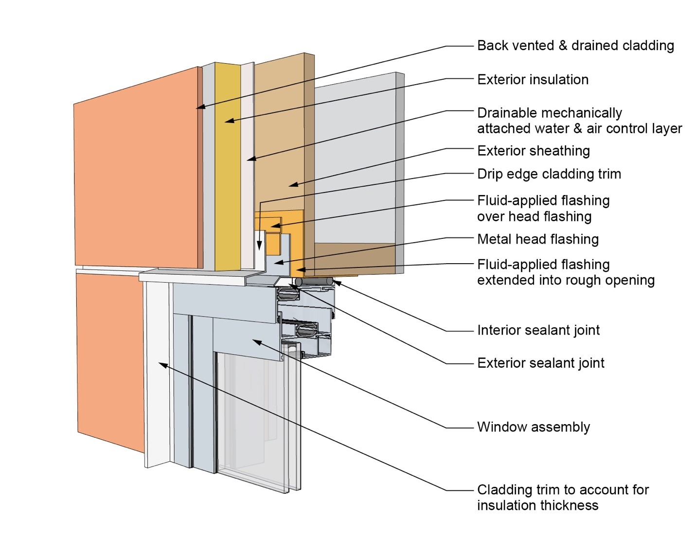
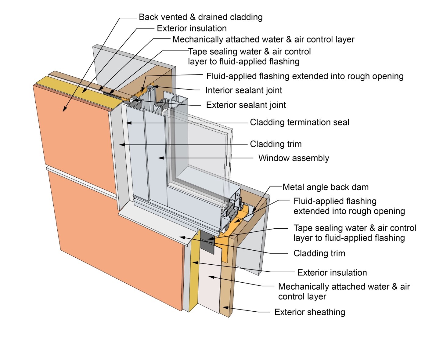
Example 4: “Innie” Windows in a Wall with Continuous Insulation over a Mechanically Attached Water and Air Control Layer Coupled with a Fluid-Applied Flashing
This example shows the same approach as is shown in Example 2, but with continuous insulation added to the outside of the mechanically attached water and air control layer. Mechanically attached water and air control layers are typically building papers, building wraps and house wraps. They are sometimes referred to as water or weather resistant barriers (WRB’s). Figures 12, 13, and 14 illustrate Example 4. In addition to the details mentioned in Example 2, the key take aways include:
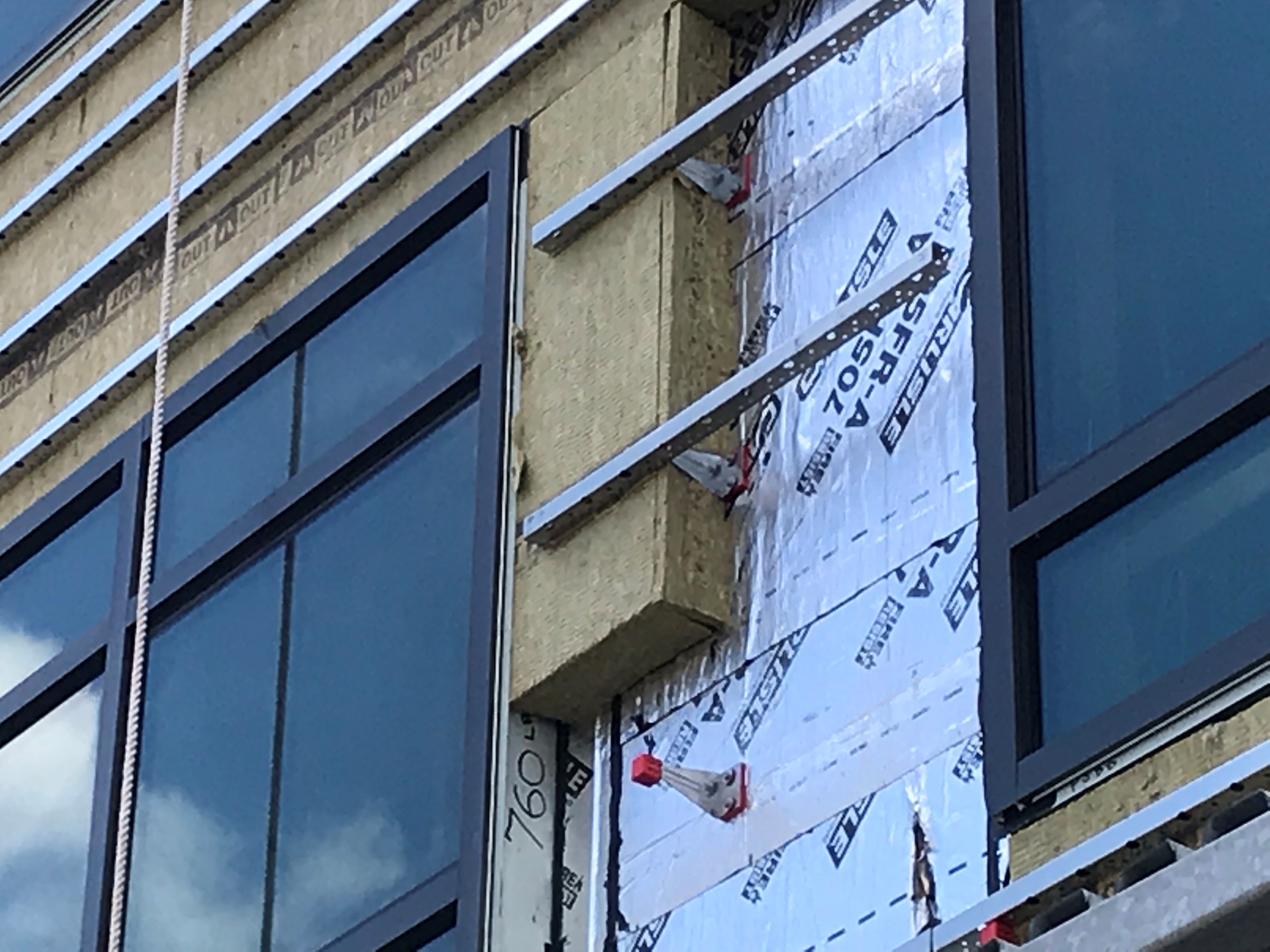
- A cladding trim closure at the perimeter of the window opening is used to account for the thickness of the continuous insulation and to direct water to the exterior of the cladding.
- A drainable house wrap or textured mechanically-attached water and air control layer is used to create a gap between the continuous insulation and the sheathing to allow for drying and movement of moisture to reduce moisture concentrations (“hygric redistribution”).
- Note that there is a minor difference with respect to the installation of the cladding drip edge trim at the head compared to Example 2. In this example the drip edge trim is lapped under the mechanically attached water & air control layer (Figure 12) while in Example 2 the trim is reverse lapped. Both approaches work. The choice of approach is typically dependent on sequencing. In both approaches the primary water control layer is the head flashing. It is key that the head flashing is lapped under the mechanically attached air & water control layer.
Source
Source
Source
Example 5: “Outie” Windows in a Wall with Continuous Insulation over a Fluid-Applied Water and Air Control Layer Coupled with a Fluid-Applied Flashing
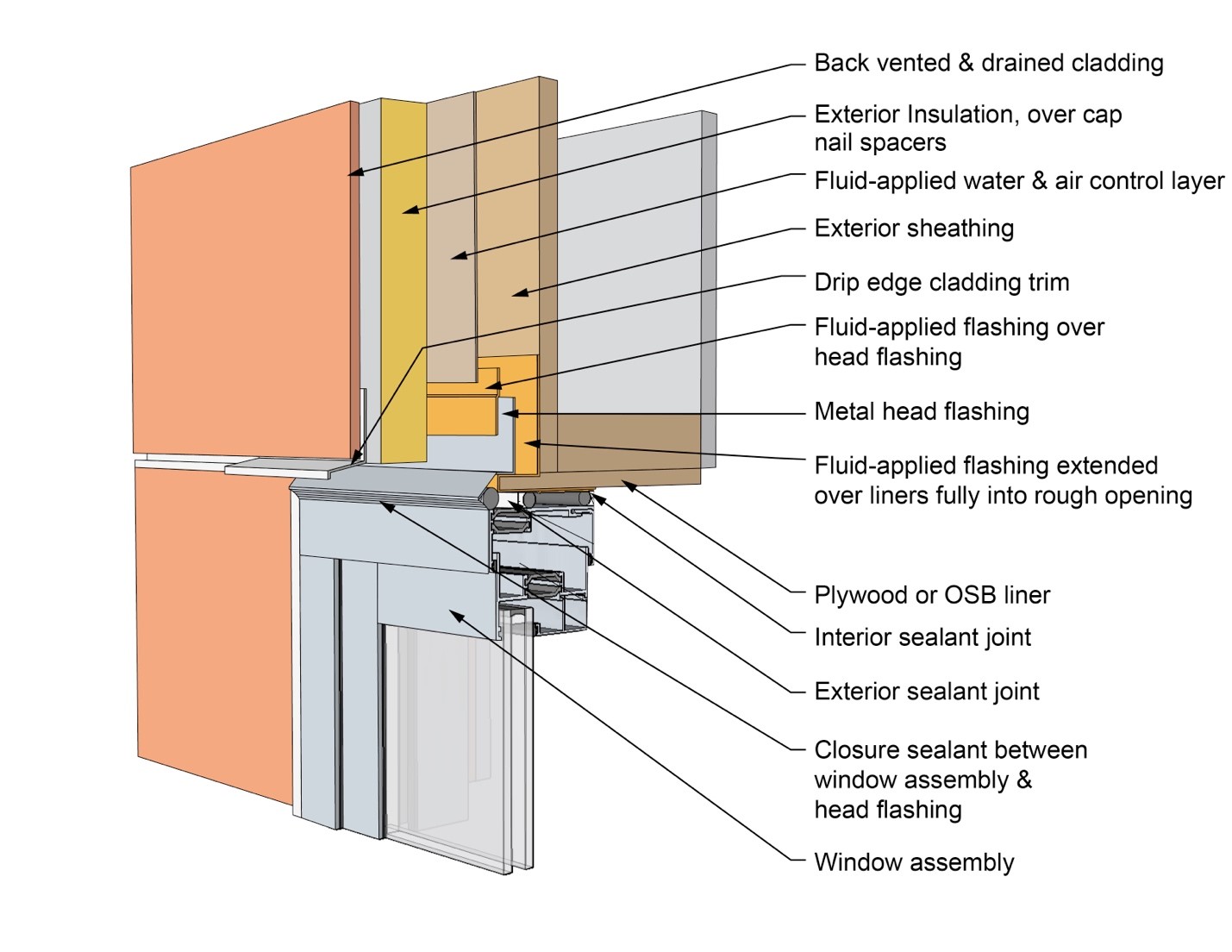
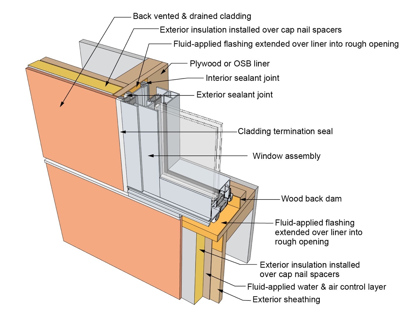
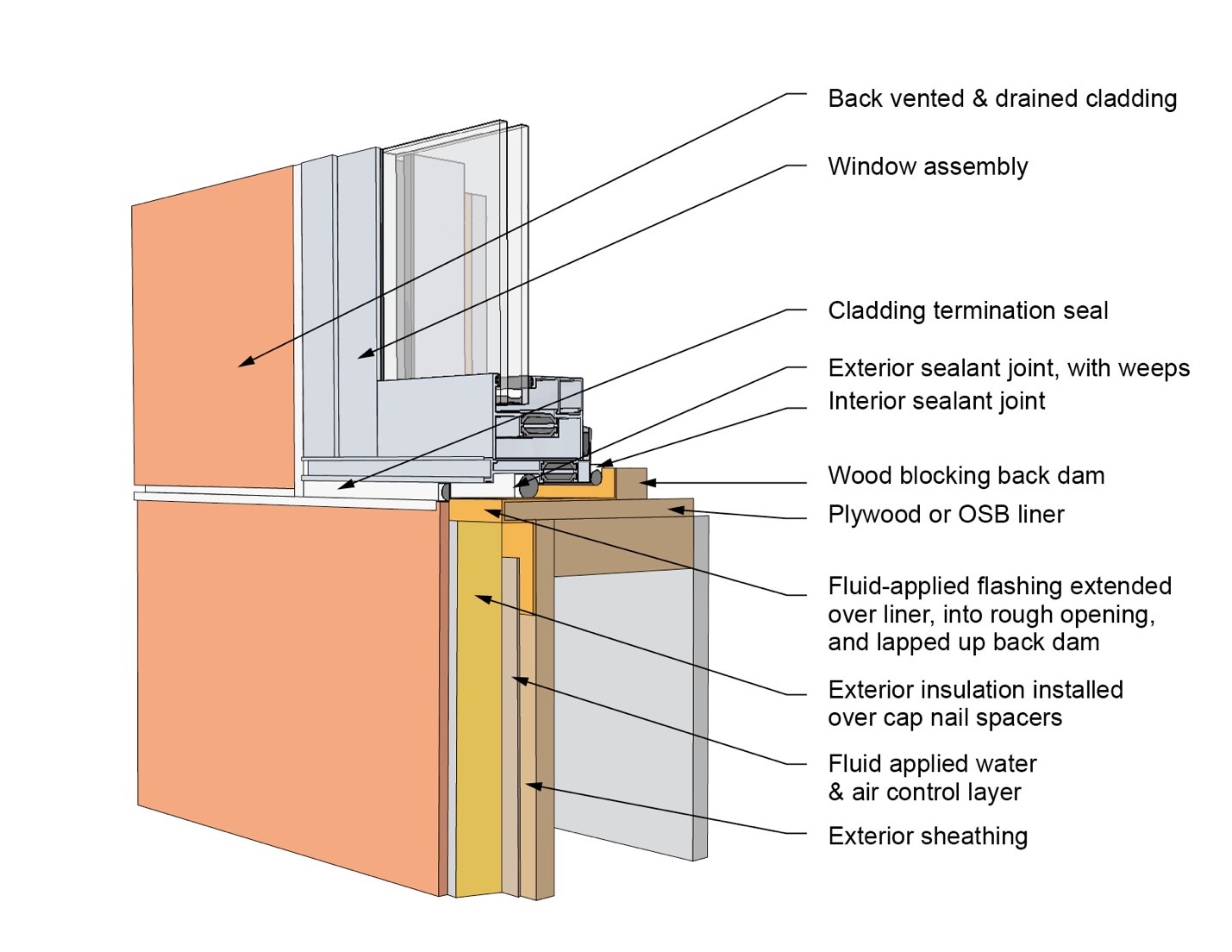
In this example continuous insulation is used and the windows are located “outboard” and flush with the cladding system. The same water control approach as is shown in Example 1 is shown here, with modifications to allow for the extra thickness of the continuous insulation. See Figures 15, 16, and 17. Other than the details described for Example 1, key aspects include:
- Plywood or OSB “liners” are installed as part of the rough opening for structural, water management, and air management reasons. The plywood/OSB lining extends outward to line up flush with the exterior surface of the continuous insulation. It is necessary to coat the plywood/OSB lining with a fluid-applied flashing system extending from inside the rough opening, around the liner to the face of the exterior sheathing, and outward along the face of the exterior sheathing for several inches.
- Closure sealant is used between the head flashing and the window to close the gap created by the thickness of the liner (Figure 15).
- Cap nails are used to create a gap to allow drainage between the fluid-applied water and air control layer and the continuous insulation. If a drainable house wrap is used as the water and air control layer instead of a fluid-applied product, then the cap nails are unnecessary.
- A wood back dam is used on the sill rather than a metal back dam as shown in other examples. Either approach will work as long as the sill flashing laps up the back dam as shown (Figures 16 and 17).
Source
Source
Source
Ensuring Success
The design details of any window installation should be reviewed for continuity of the control layers – specifically the water control layer and the air control layer. Unique details should be “mocked up” to verify constructability. Installation of windows should be field verified by water leakage testing using ASTM E1105 – Standard Test Method for Field Determination of Water Penetration of Installed Exterior Windows, Skylights, Doors, and Curtain Walls, by Uniform or Cyclic Static Air Pressure Difference.
Region
In IECC Climate Zones 4 and higher, continuous exterior insulation is common and window installation needs to accommodate the continuous exterior insulation. See Examples 4 and 5 on the Description Tab.
Compliance
More Info
References and Resources
*For non-dated media, such as websites, the date listed is the date accessed.
Contributors to this Guide
The following authors and organizations contributed to the content in this Guide.
Building Science Corporation
Questions? Comments? Contact our webmaster.