

Scope
Install fresh air ventilation inlets away from contamination sources.
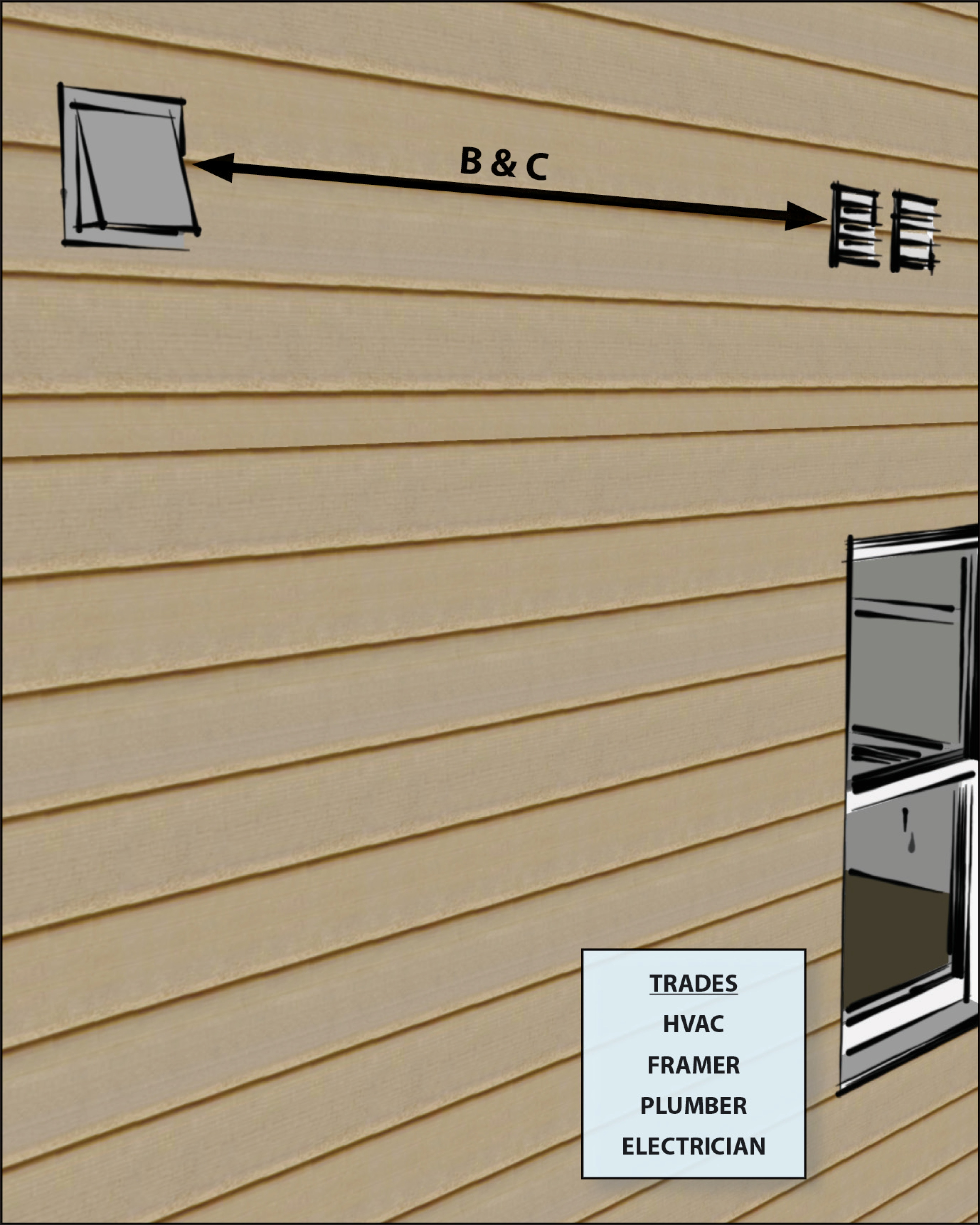
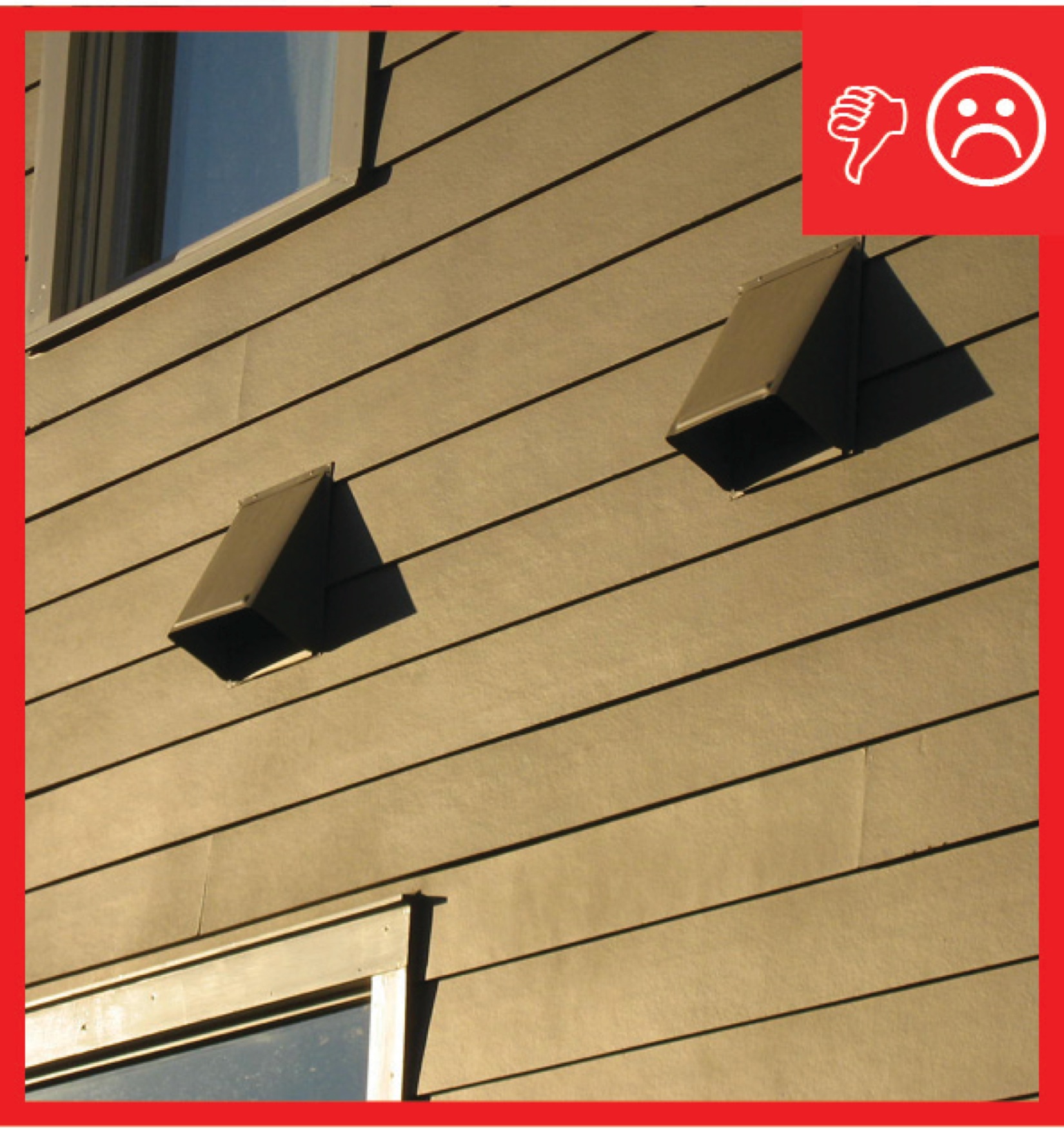
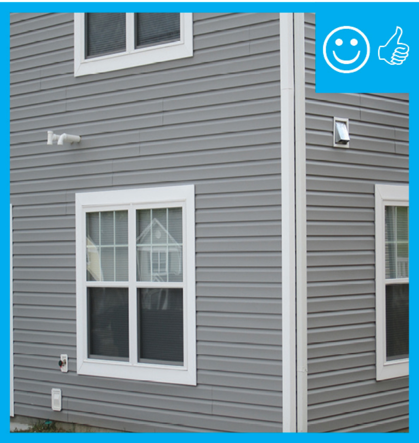
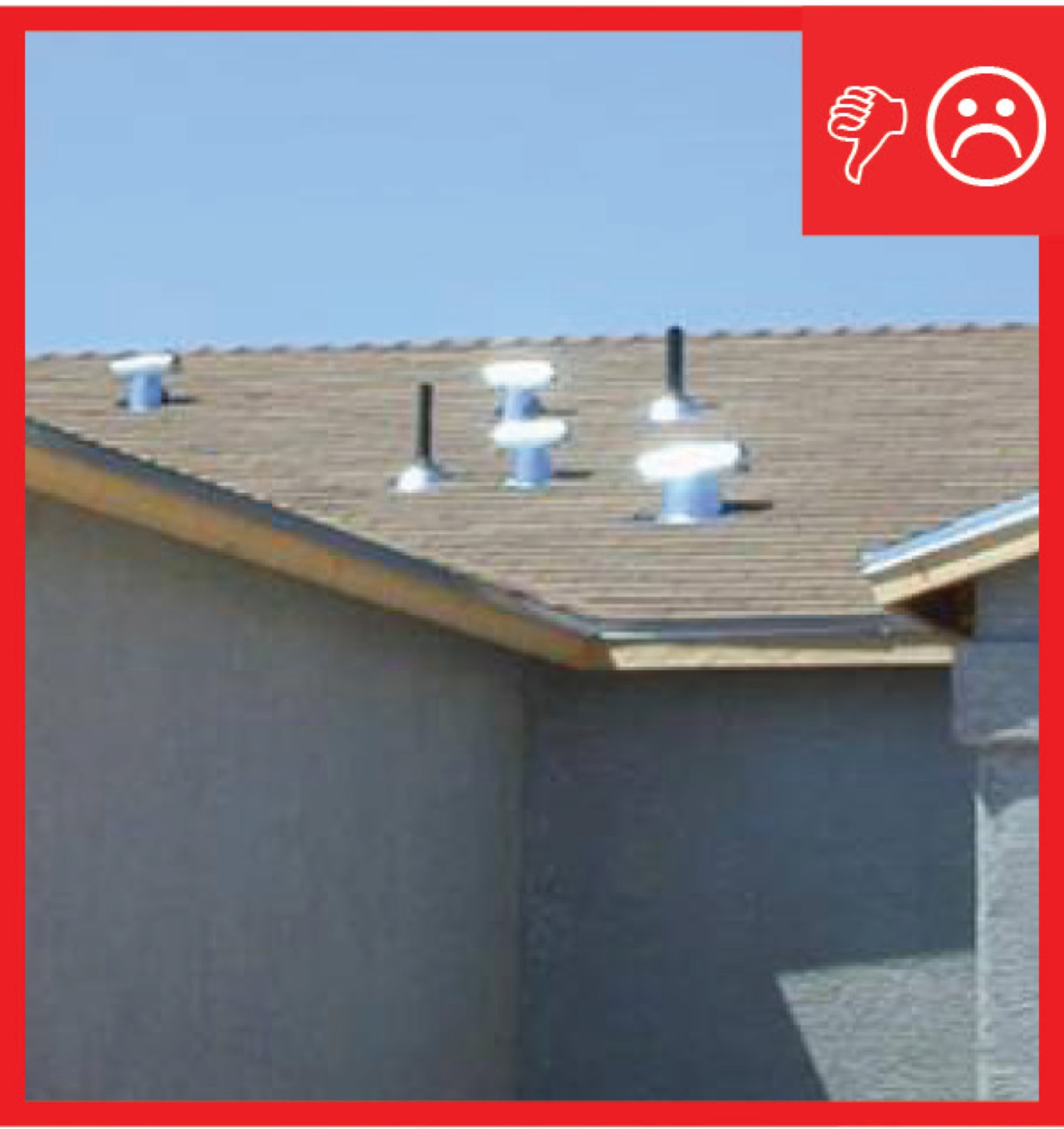
- Install air inlets at least 10 feet away from all contamination source terminations. Install air inlets in the wall at least 3 feet away from dryer exhausts and contamination sources that exit through the roof (as required by ENERGY STAR Single-Family New Homes).
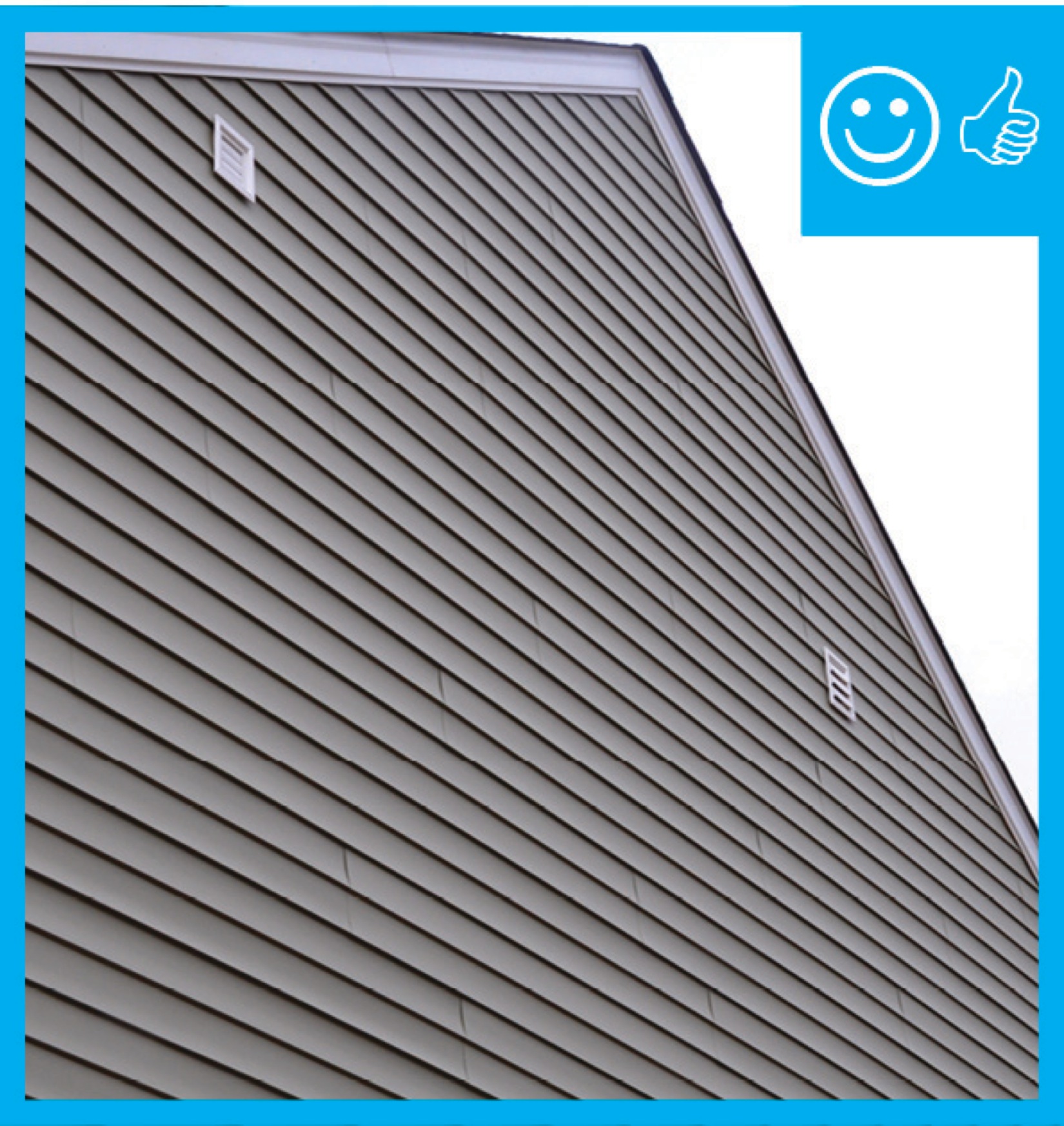
- Install air inlets at least 2 feet above grade or above the roof deck (as required by ENERGY STAR Single-Family New Homes). Note: it is easier to install an air inlet at the gable end of the house than to try to lift it off the roof 2 to 4 feet.
- Ensure that ventilation air comes directly from outdoors and not from adjacent dwelling units, garages, crawlspaces, or attics.
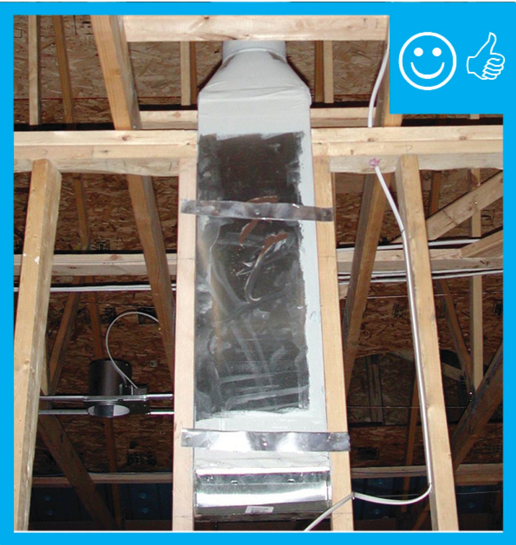
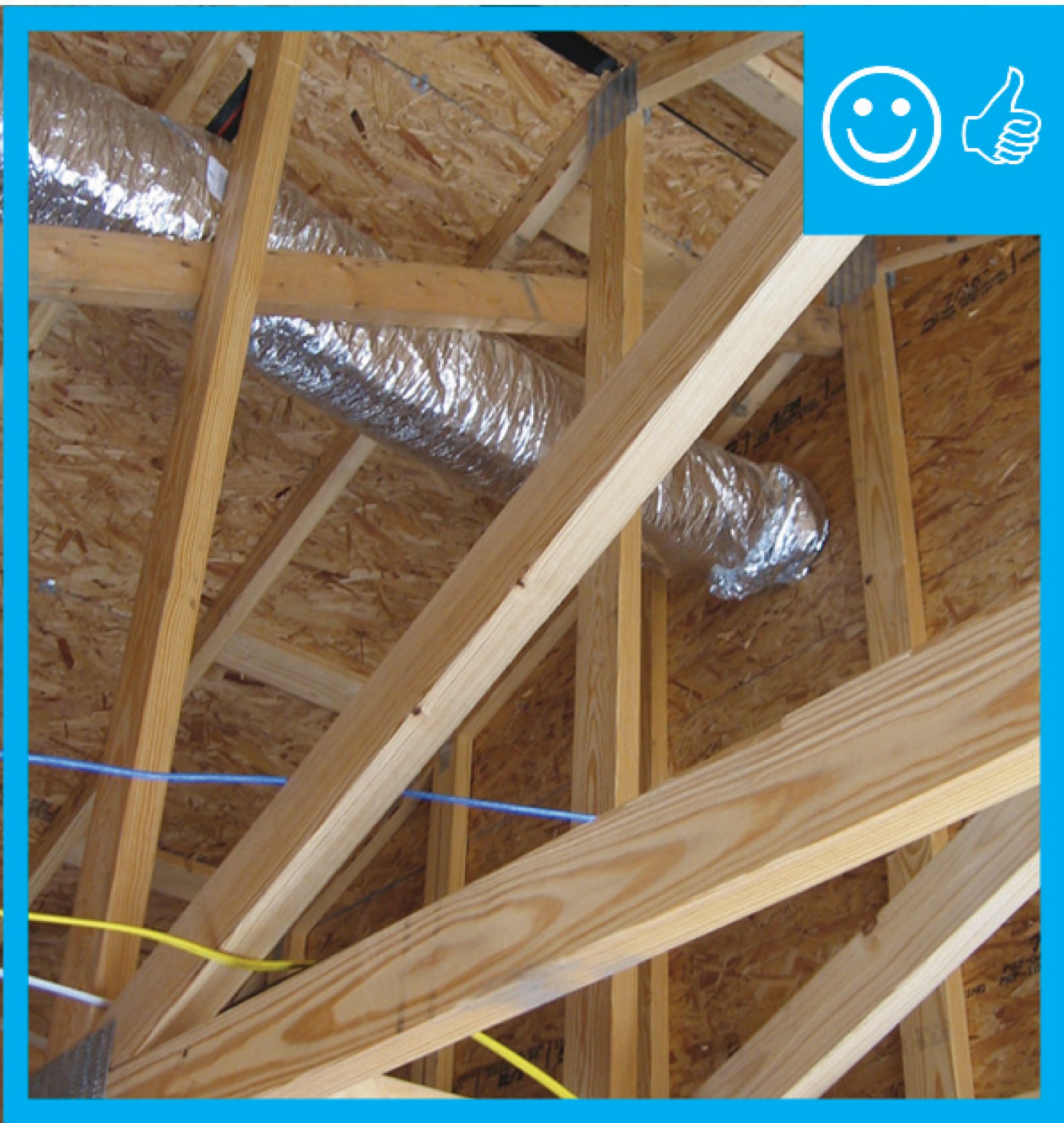
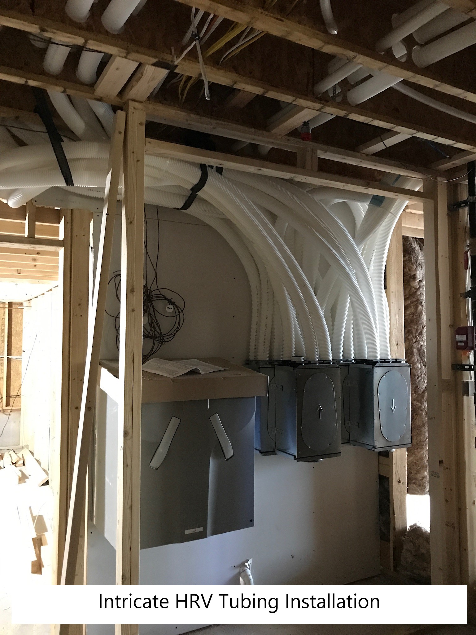
- Install the air inlet duct in a location with the shortest, most direct path possible to the air handler unit, HRV, or ERV.
- Stretch the duct tight and support it adequately to minimize sagging and kinks.
- Air seal around the intake duct termination and seal the duct to the HRV/ERV or return side of the air handler with mechanical fasteners and metal tape or mastic.
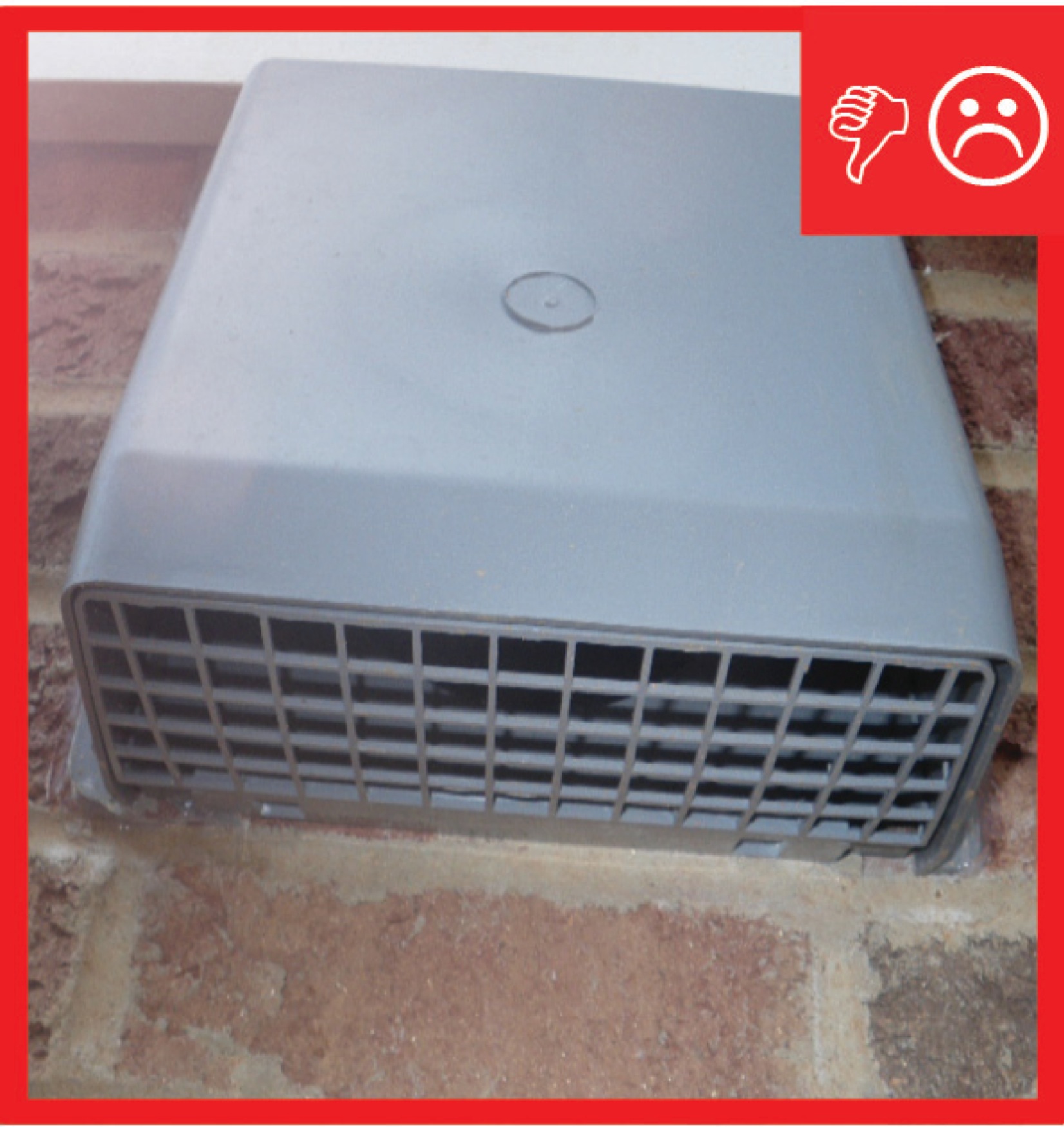
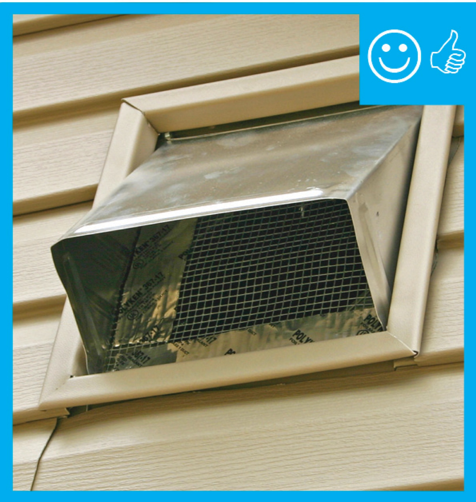
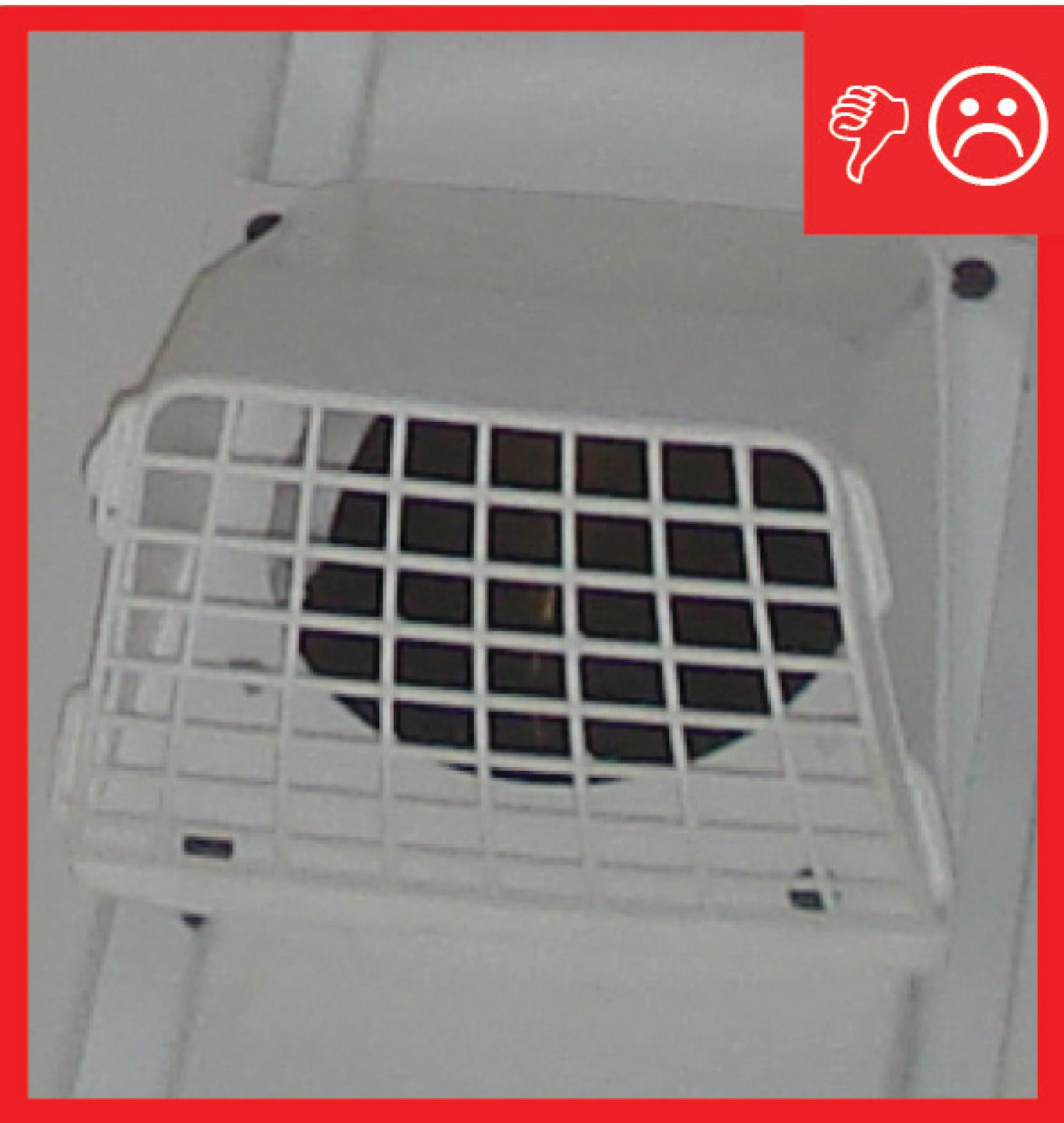
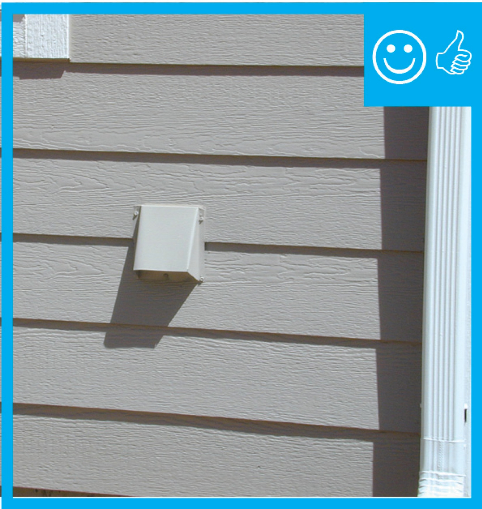
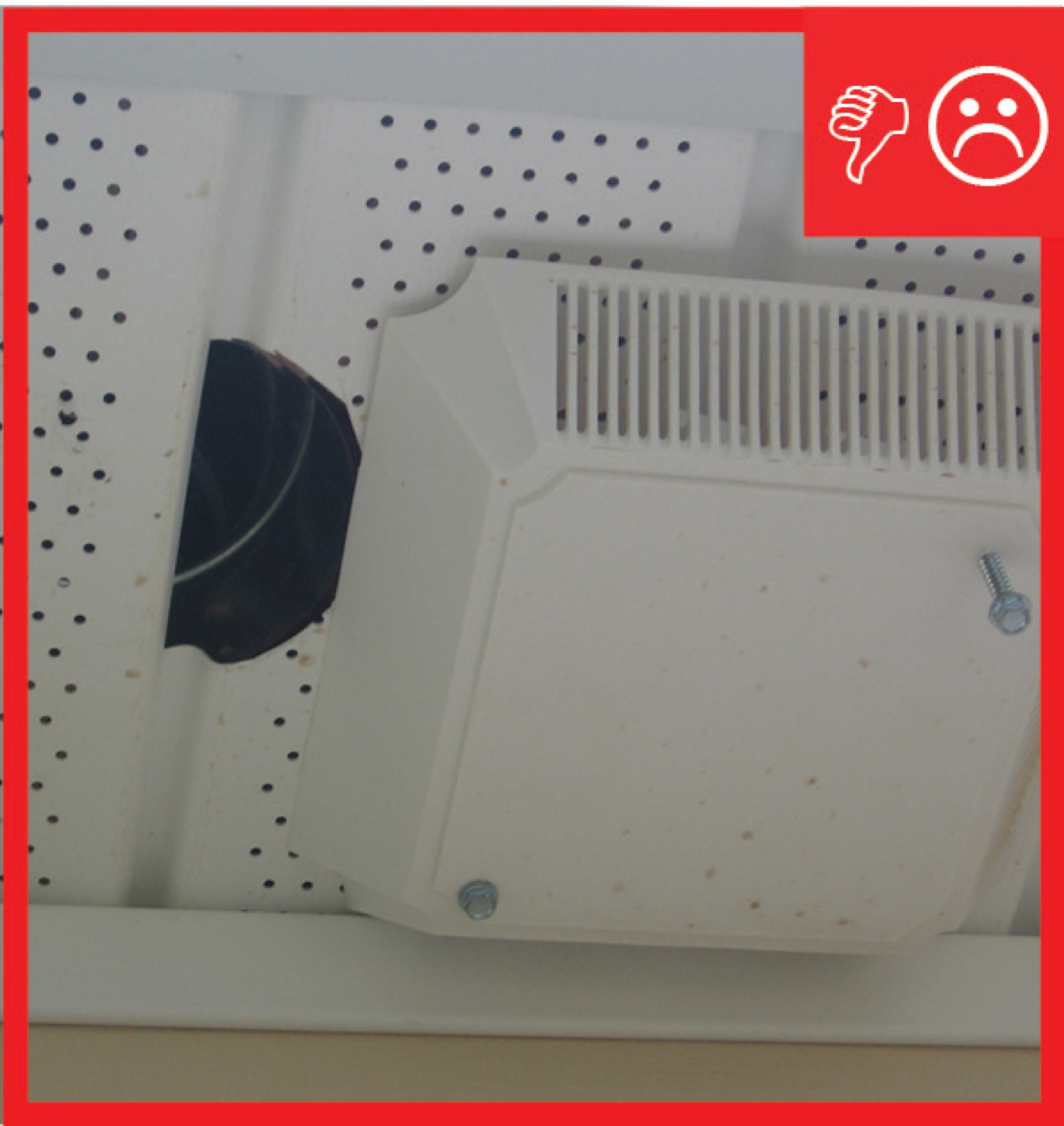
- Install a ≤ 0.5-in.-mesh screen on all air inlets to keep out rodents, insects, and debris, except use a louvered damper rather than a mesh screen on clothes dryer vents.
See the Compliance Tab for links to related codes and standards and voluntary federal energy-efficiency program requirements.
Description
When a home has a balanced ventilation system that uses a heat recovery ventilator (HRV), energy recovery ventilator (ERV), or central-fan-integrated supply ventilation, fresh air is brought into the home through a ventilation air inlet. To ensure good air quality, the inlet should be placed in a location away from possible sources of contamination, and where it has unobstructed access to clean air.
Possible contamination sources include bathroom exhaust fans, plumbing vent pipes, kitchen exhaust fans, dryer exhaust vents, furnace exhaust vents, water heater exhaust vents, fireplace flues, and whole-house fans. The locations for these outlets and inlets should be specified on plans. In addition, the HVAC contractor should coordinate with other subcontractors, including the framers, plumbers, and electricians, at the beginning of construction to determine the proper placement of both air inlets and contamination source terminations.
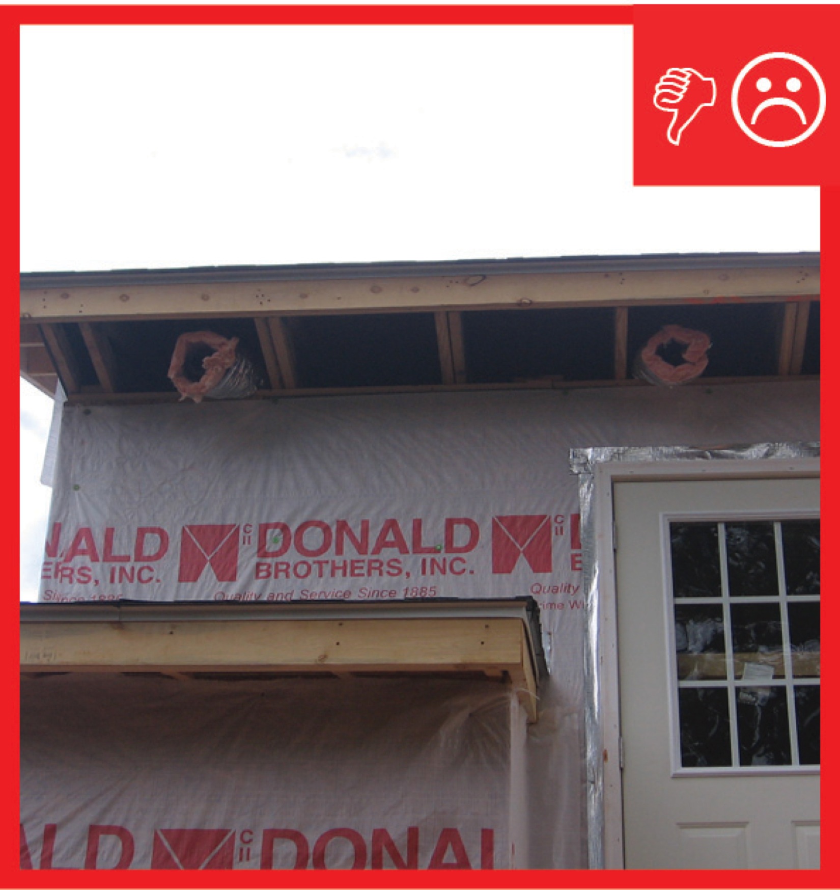
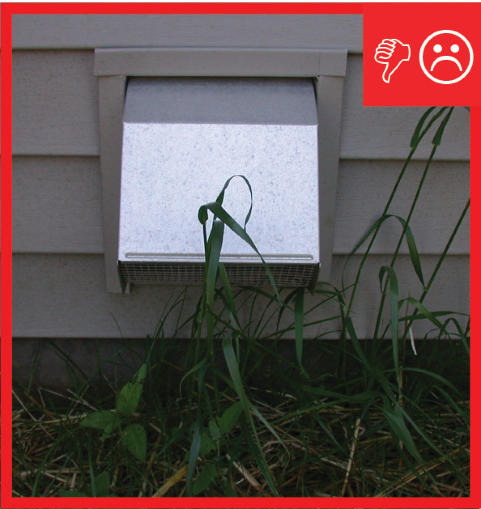
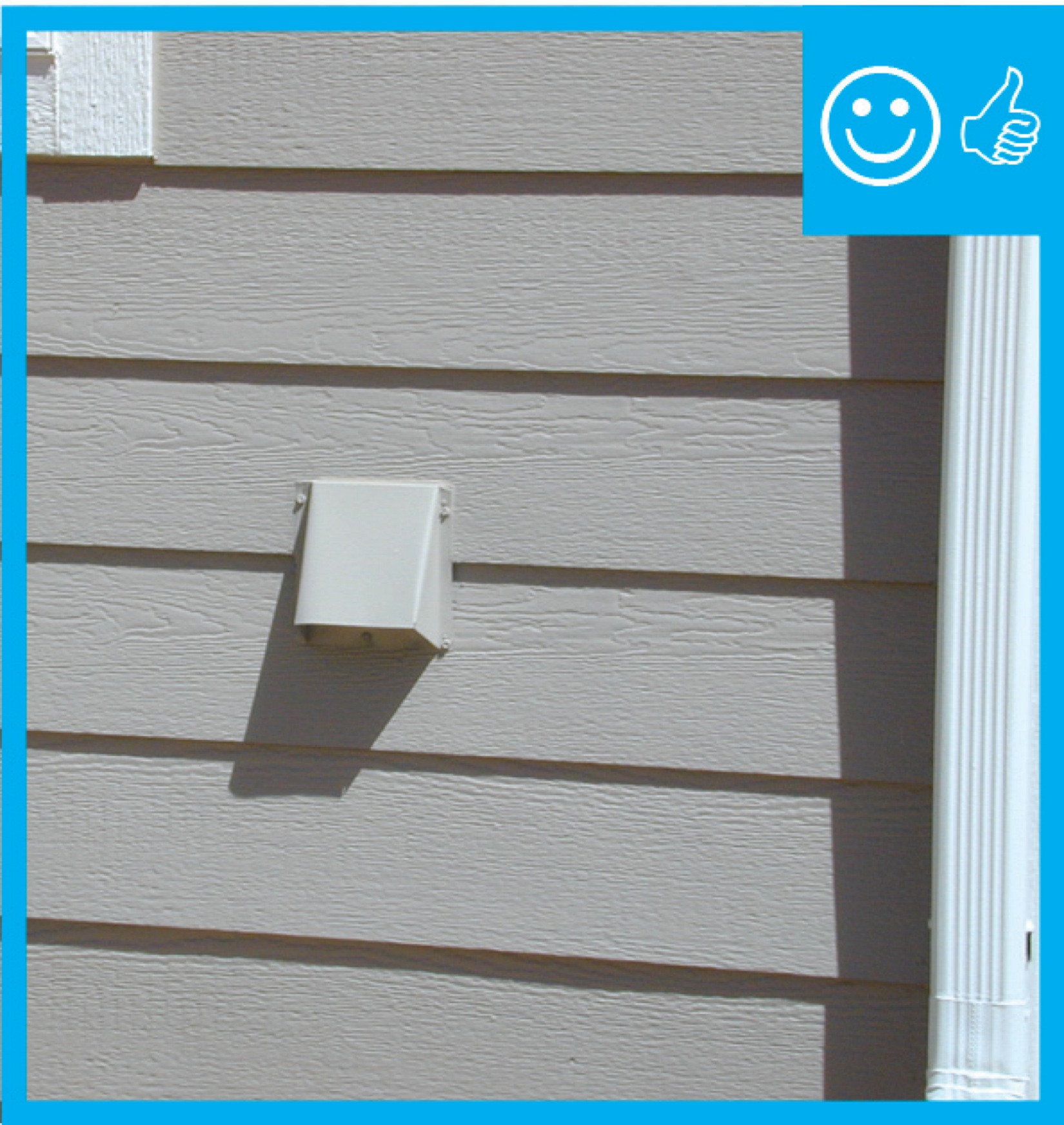
The air inlet should be located high enough above the ground, or roof surface, to prevent accumulated snow from piling up over it, rainwater from splashing into it, and plants from growing into it. It should be located outside, not in an attic, crawlspace, garage, or attached dwelling. The inlet should be covered with a mesh screen to prevent animal and insect entry. Ideally, it should be placed in a location where the home owner can check and clean it regularly.
Where to Install Ventilation Air Inlets
1. Verify locations of all contamination source terminations.
2. Install fresh air inlets so that they are
- at least 10 feet away from all contamination source terminations
- at least 3 feet away from dryer exhausts and contamination sources exiting through the roof
- at least 2 feet above grade or above the roof deck
* Note: it is easier to install an air inlet at the gable end of the house than to try to lift it off the roof 2-4 feet.
3. Install the air inlet duct in a location with the shortest, most direct path possible to the air handler unit, HRV, or ERV. Stretch the duct tight and support it adequately to minimize sagging and kinks. Air seal around the intake duct termination and seal the duct to the HRV/ERV or return side of the air handler with mechanical fasteners and metal tape or mastic.
4. Install a ≤ 0.5-in.-mesh screen on all air inlets to keep out rodents, insects, and debris, except clothes dryer vents which should have a louvered damper instead. See the guide Proper Clothes Dryer Venting for more information.
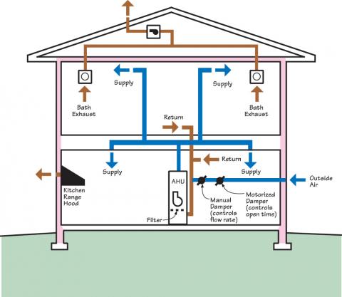
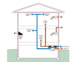
On the diagram of a house below, which has central-fan-integrated supply ventilation, the fresh air intake is located more than 4 feet above grade level and away from other contaminant sources such as other flue or exhaust pipe outlets on the house.
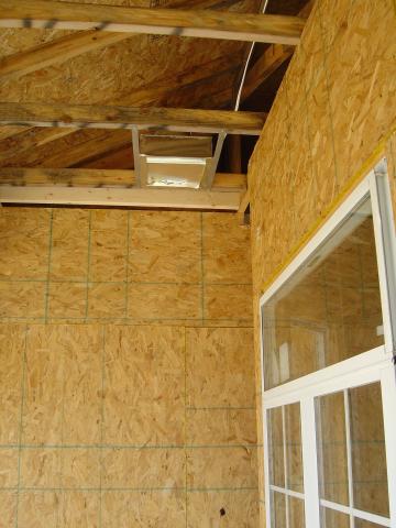
The metal frame for the fresh air intake duct grille has been installed in the ceiling of a covered porch of this home under construction.
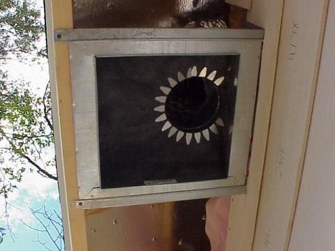
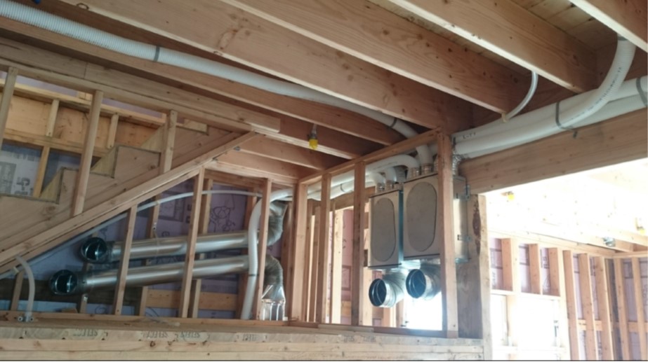
The intake and duct have been installed for the fresh air inlet in the eave of the roof of this home under construction. The grille has not yet been installed.
Ensuring Success
Visually inspect the ventilation inlet to ensure that it is at least 10 feet from any known contamination sources, at least two feet above grade and above the roof deck. Make sure the inlet is not obstructed by any objects, that the ventilation air comes from outdoors—not from a garage, attic, crawlspace, or adjacent dwelling, and that the ventilation inlet is covered with a protective screen with ≤ 0.5–inch mesh. Dryer vents should have a louvered damper, not a mesh screen, covering the outside end.
Region
No climate specific information applies.
Training
Right and Wrong Images
Source
Source
Source

Source
Source
Source
Source
Source

Source
Source

Source

Source
Source
Source
Source
Source
Source
Compliance
Retrofit
SCOPE
Guidance for the measures described in this guide is applicable to both new and existing homes.
For more information on assessing ventilation systems see the assessment guide on ventilation.
For more information on installing outdoor air inlets in existing homes see the U.S. Department of Energy’s Standard Work Specifications. Follow safe work practices as described in the Standard Work Specifications section on ventilation worker safety.
More Info
References and Resources
*For non-dated media, such as websites, the date listed is the date accessed.
Contributors to this Guide
The following authors and organizations contributed to the content in this Guide.
Sales
Balanced Ventilation = Fresh Air Balanced System
Technical Description
Fresh air balanced systems supply and filter outdoor air while exhausting an equal amount of indoor air. This type of system maintains a neutral balance in air pressure that minimizes moisture risks and optimizes mixing. These systems are often equipped with heat and moisture exchangers that optimize efficiency and comfort. This is achieved by exchanging heat and moisture between the incoming and outgoing air streams. This captures heat before it leaves the home in winter, heat before it enters the home in summer, moisture before it enters the home in summer, and moisture before it leaves the home in winter.
Questions? Comments? Contact our webmaster.