

Scope
Install insulation and an air barrier around skylight shafts.
- If non-rigid insulation is used in the wall cavities of the skylight shaft, install a rigid air barrier on the exterior side of the shaft wall framing to prevent the cavity insulation from sagging and to create a continuous thermal barrier.
- Seal all seams, gaps, and holes in the air barrier with caulk or foam. Rigid air barrier material could include rigid foam insulation, drywall, plywood, or OSB, among others.
- If spray foam insulation is used for the wall cavity insulation, the spray foam can serve as the air barrier if it is at least 5.5 inches thick if open-cell or at least 1.5 inches thick if closed-cell spray foam insulation.
- Ensure that the air barrier is continuous and in full contact with the insulation.
- ENERGY STAR requires that an air barrier be installed at the exterior vertical surface of the wall insulation in all climate zones and also that an air barrier be installed at the interior vertical surface in IECC Climate Zones 4-8 (ENERGY STAR).
See the Compliance Tab for links to related codes and standards and voluntary federal energy-efficiency program requirements.
Description
When skylights are installed, special attention must be paid to insulating the vertical shafts extending from the roof to the ceiling. Unsealed attics are often insulated along the attic floor with blown fiberglass or cellulose insulation. A different type of insulation will need to be installed along the skylight shaft walls, one that will maintain full alignment (or contact) with the back side of the sheathing for the height of the skylight shaft walls and that will maintain at least the minimum required depth of insulation along the full height. Skylight shaft walls should be insulated to the same R-value as other exterior walls if the attic they pass through is not insulated.
There are several options for insulating skylight shafts. One option to consider, especially if several skylights are being installed, is to make the attic part of the conditioned space of the home by installing insulation at the roof deck, either by spray foaming along the underside of the roof deck or installing rigid foam above the roof deck, or by constructing the roof with structural insulated panels (SIPs). This insulated attic would also provide a conditioned space for any HVAC equipment installed in the attic.
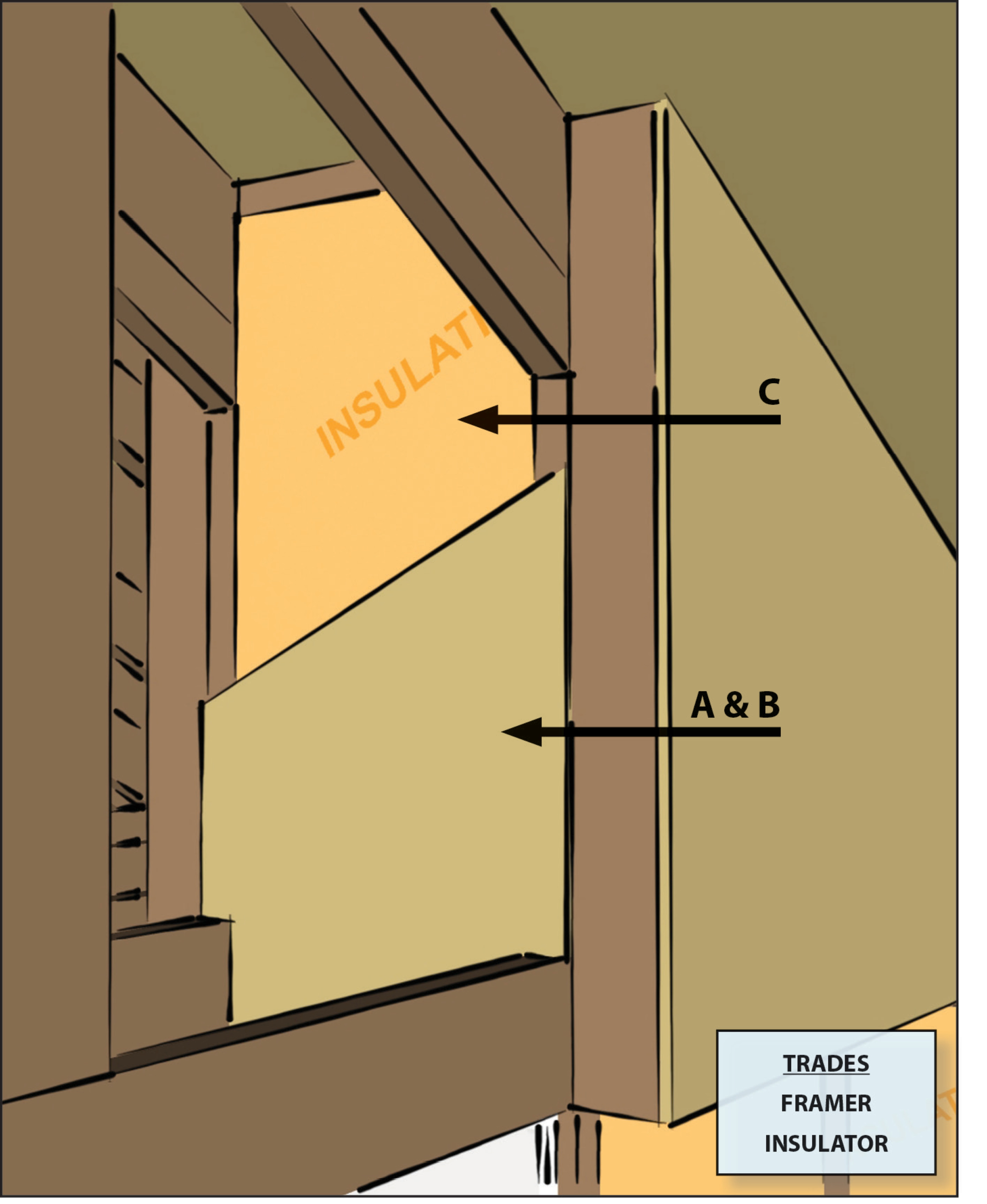
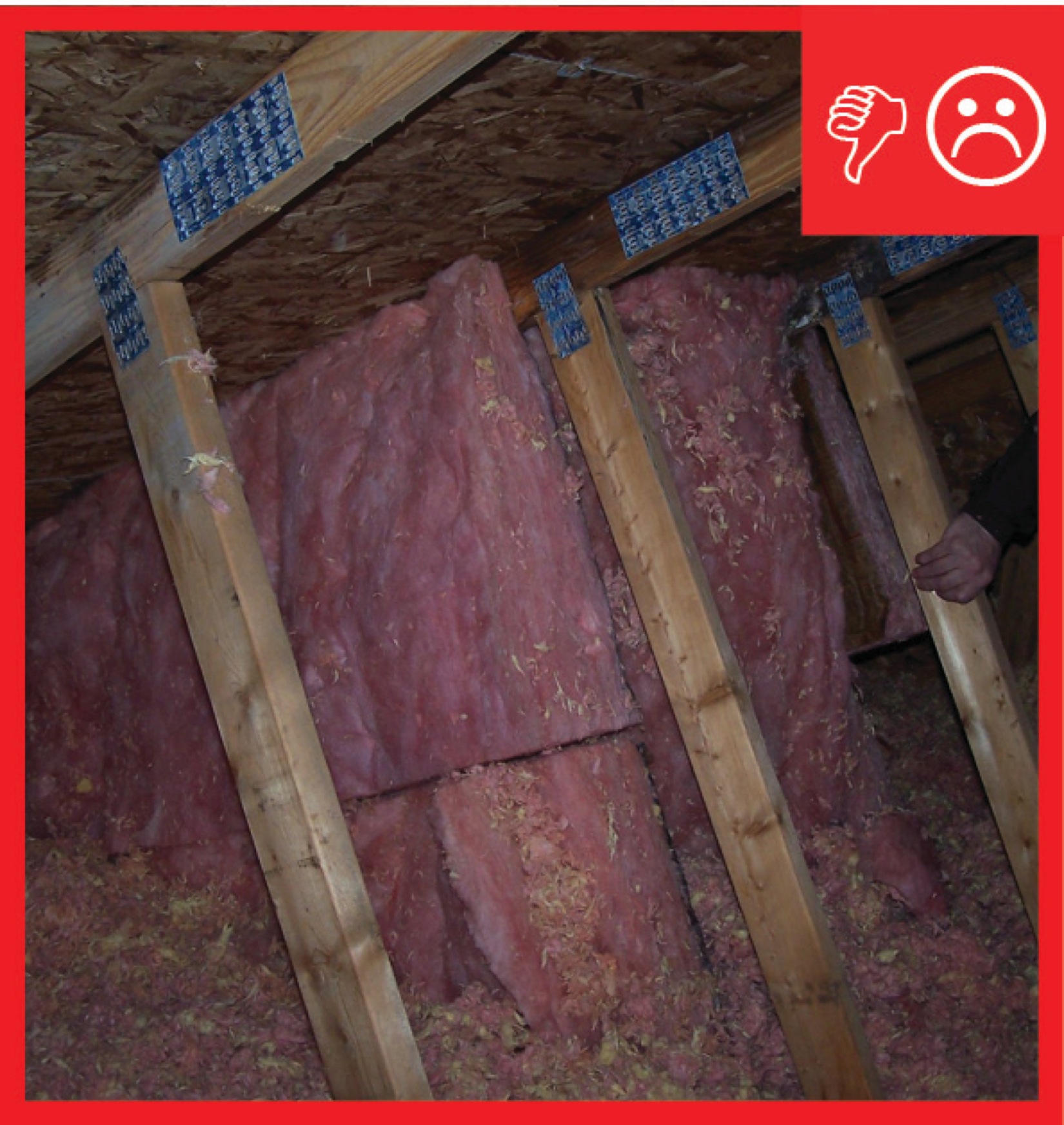
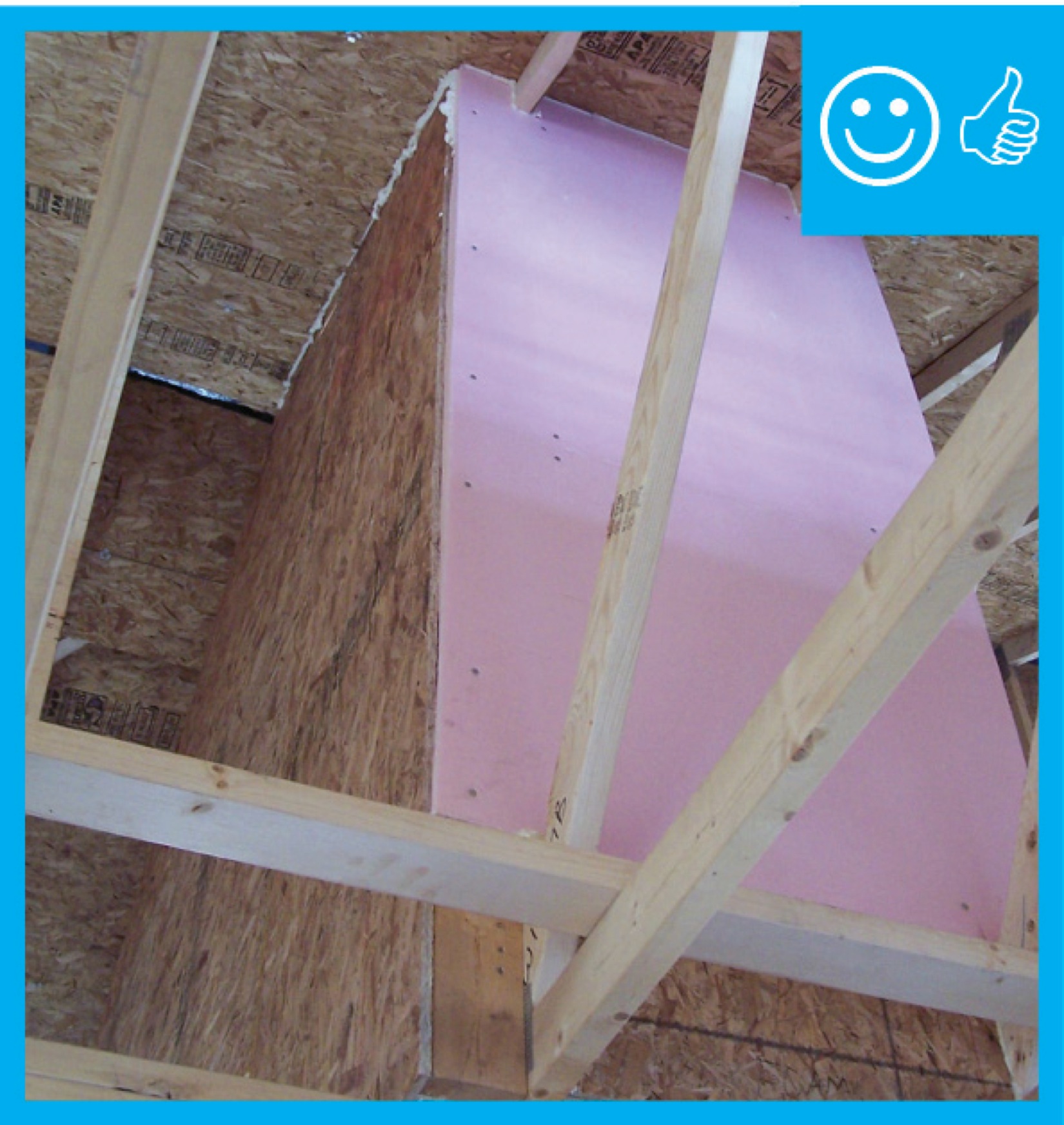
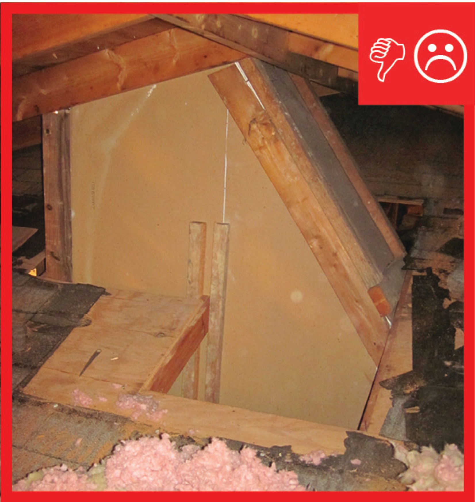
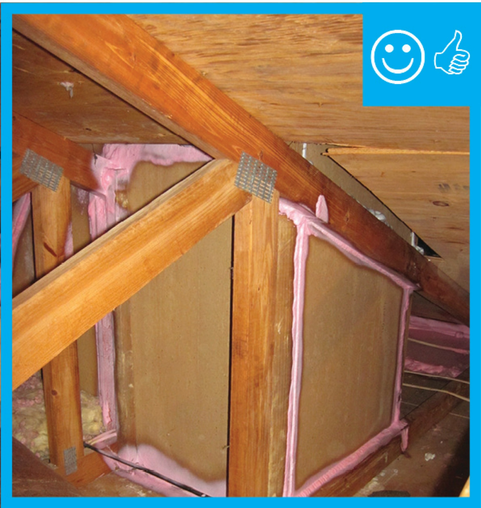
If the skylight shafts are installed in a vented, uninsulated attic, then the sides of the skylight shaft should be insulated. This can be accomplished using spray foam or rigid foam, or by constructing the shaft walls with SIPs. Fiberglass batt insulation is not recommended for insulating the skylight shaft walls because it can settle or pull away from the wall. If batt insulation is used, it should be covered with a rigid material such as rigid foam, which will provide an interior air barrier and ensure that the batts will not slide down or fall away from the wall. These materials may be installed by insulators, framers, or subcontractors or vendors hired specifically to install the skylight. This task should be included in the contract for the appropriate trade depending on the workflow at the specific job site.
How to Insulate a Skylight Shaft
- Select the skylight size and location to avoid cutting roof or ceiling rafters, if possible. (House designs that use 24-in on-center fully aligned framing members are less likely to require cutting of studs for skylight installation.) Follow the manufacturer’s instructions to install the skylight on the roof deck, properly flashing and integrating the skylight frame with roofing materials to minimize the risk of water intrusion. The roof opening is framed with headers, with framing lumber run horizontally across the opening and securely nailed to the rafters to support the structure.
- Install headers across the ceiling opening as you did for the roof opening, using a single header at each end if no ceiling joists are cut or double headers if a ceiling joist has to be cut. If the light shaft will be flared, cut the joist at the angle of the flare.
- Cut 2x4 studs (or 2x6 to allow for more cavity insulation) for the corners of the light shaft, angled on each end to fit flush against the rafters and ceiling joists. Next, place studs 24-inch on-center around the opening. Nail 2x2 cleats to the inside edges of the corner studs or use drywall clips to serve as backing for the drywall.
Or, frame the shaft with structural insulated panels (SIPs) following the manufacturer’s instructions for air sealing the corners, seams, and top and bottom edges.
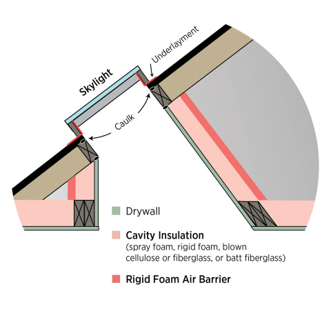
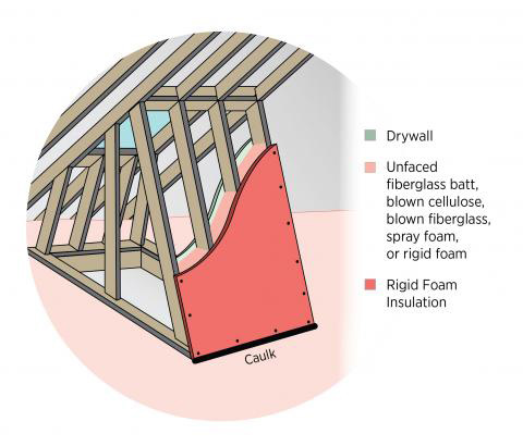
- Fill the stud cavities with spray foam, batt insulation, or rigid foam (Figures 1 and 2). Next, cover them with a layer of rigid foam to achieve the R-value level required for your climate zone.
Or, nail rigid foam in place over the studs and fill the cavities with blown cellulose or blown fiberglass.
- Caulk drywall and rigid foam to framing at all edges. Seal any seams in the rigid foam with caulk, tape, or foam.
- Paint drywall with latex paint to serve as the vapor barrier.
How to Insulate a Solar Tube
- Install the tube according to the manufacturer’s instructions.
- Insulate the solar tube with plastic-covered flex duct insulation.
- Or - Wrap the tube with unfaced fiberglass batt insulation. Secure the insulation in place with ties. Cover the unfaced batt insulation with flexible foil-faced insulation and secure it with ties and metal tape.
- Use spray foam or caulk to air seal the solar tube to the ceiling from above.
- Caulk under the decorative ring on the room side of the ceiling.
For more on installing solar tubes, see the guide Light Tubes.
Ensuring Success
An infrared camera can be used to detect heat loss around the skylight. The insulation installation should be visually inspected by the site supervisor.
Region
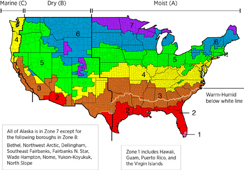
The map in Figure 1 shows the climate zones for states that have adopted energy codes equivalent to the International Energy Conservation Code (IECC) 2009, 12, 15, and 18. The map in Figure 2 shows the climate zones for states that have adopted energy codes equivalent to the IECC 2021. Climate zone-specific requirements specified in the IECC are shown in the Compliance Tab of this guide.

Training
Right and Wrong Images
Source
Guide describing details that serve as a visual reference for each of the line items in the Thermal Enclosure System Rater Checklist.
Source
Guide describing details that serve as a visual reference for each of the line items in the Thermal Enclosure System Rater Checklist.
Source
Guide describing details that serve as a visual reference for each of the line items in the Thermal Enclosure System Rater Checklist.
Source
Guide describing details that serve as a visual reference for each of the line items in the Thermal Enclosure System Rater Checklist.

Source
Guide describing details that serve as a visual reference for each of the line items in the Thermal Enclosure System Rater Checklist.
Videos


Compliance
Retrofit
SCOPE
Insulate and air seal the shaft walls of an existing skylight.
- Inspect the existing skylight for signs of water leakage; repair flashing and replace damaged framing as necessary.
- Choose an air barrier material - either rigid insulation, drywall, or sprayed polyurethane foam insulation.
- If the air barrier will be rigid insulation or drywall, remove any existing insulation if insufficient or sagging. Fill the skylight shaft framing cavities with unfaced batt insulation. Caulk framing then cover with rigid insulation or drywall. Tape and seal all joints in the rigid insulation or drywall.
- If the air barrier will be sprayed polyurethane foam, remove any existing insulation and fill the cavities with either open- or closed-cell spray foam.
- Follow the steps in the Description tab.
For more information on conditions that may be encountered when working with walls in existing homes, see the assessment guide on attics.
See the U.S. Department of Energy’s Standard Work Specifications. for more on air sealing and insulation skylights and follow safe work practices as described.
DESCRIPTION
Retrofit an existing skylight shaft by adding an air barrier and insulation to the shaft walls. This work will be performed from the attic side of the skylight shaft, typically using rigid insulation or drywall or sprayed polyurethane foam insulation. If the air barrier will be rigid insulation or drywall, the framing cavities should be filled with insulation. Unfaced fiberglass batt insulation is typical, but almost any unfaced cavity insulation may be used as long as it will remain in place with minimal settling. Where sprayed polyurethane foam (SPF) insulation is used as the air barrier, follow the applicable code requirements regarding the use of a thermal or ignition barrier. Sometimes this barrier is a coating that is sprayed directly onto the surface of the SPF. In other cases material such as drywall is used as the thermal barrier to separate the SPF from adjacent construction.
This work will be performed from inside the attic so use safe work practices and be aware of hazardous conditions as described in the attic assessment guide.
How to Insulate and Air Seal Skylight Shaft Walls
- Inspect the existing skylight for signs of water leakage, such as water stains and rot. Repair skylight flashing (from the roof exterior) and replace any damaged framing as necessary.
- Set aside existing attic floor insulation to expose the framing at the base of the skylight shaft to be air sealed.
- Determine what material will constitute the air barrier around the shaft wall - typically either rigid insulation, drywall, or sprayed polyurethane foam insulation.
- If using rigid foam or drywall as the air barrier:
- Remove any existing insulation in framing cavities around the skylight shaft if it is insufficient, wet, sagging, or pest infested. If the insulation is unfaced batt in good shape and of sufficient quantity, leave it in place.
- Install new unfaced batt insulation as needed to completely fill the framing cavities of the skylight shaft.
- Apply a thick bead of caulk to the face of framing at the top, bottom, and sides on each side of the shaft.
- Nail or screw the rigid insulation or drywall in place over the caulked framing, as shown in the Description tab. Tape and seal all joints in the rigid insulation or drywall.
- If the air barrier to be used is sprayed polyurethane foam (SPF) insulation, remove any old insulation and fill the cavities of the skylight framing with the SPF. Both open- and closed-cell SPF insulations are acceptable in any climate zone for this application.
- Replace floor insulation around the base of the skylight shaft.
COMPLIANCE
See Compliance tab.
More Info
References and Resources
*For non-dated media, such as websites, the date listed is the date accessed.
Contributors to this Guide
The following authors and organizations contributed to the content in this Guide.
Pacific Northwest National Laboratory
Building Science Corporation, lead for the Building Science Consortium (BSC), a DOE Building America Research Team.
Sales
Fully Aligned Air Barriers = Whole-House Draft Barrier
Technical Description
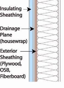
A whole-house draft barrier is a continuous layer of air-tight materials that block air leaks. This barrier can be integrated with other materials to also function as a water barrier, thermal barrier, and vapor barrier. For example, rigid foam insulation can be used to block thermal flow as well as air flow when seams are sealed with tape, caulk, adhesives, or liquid-applied sealants. Some rigid foams have an integrated water control layer as well. Additionally, drywall can serve as an interior air barrier when the seams are taped and spackled, and caulk, spray foam, or gaskets are used to seal around wiring, plumbing, and other penetrations. It also serves as the vapor barrier when finished with paint. Insulation should be in full contact with the air barrier layer.
Questions? Comments? Contact our webmaster.