

Scope
When constructing homes with slab-on-grade foundations with turned-down footings in areas known for earthquakes, connect the house walls to the foundation and connect the structural elements to each other to withstand seismic activity:
- Provide wall-to-slab-on-grade foundation diaphragm anchors
- Install building bracing
- Install control layers to improve the energy efficiency and durability of the structure, including a rain control layer, an air control layer, a vapor control layer, and a thermal control layer.
See the Compliance Tab for links to related codes and standards and voluntary federal energy-efficiency program requirements.
Description
Seismic Design Approach
Most of the damage to buildings during earthquakes is caused by lateral movements, which disconnect the house from its foundation. These lateral loads (“shear”) due to ground movement need to be transferred to the ground. New homes and existing homes need to be connected to their foundations and the structural elements should be connected to each other to withstand seismic activity. Additionally, the foundation should be insulated to be thermally efficient. This guide describes options for providing seismic and thermal resistance in slab-on-grade concrete foundations with turn-down footings.
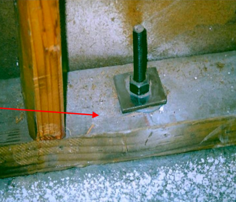
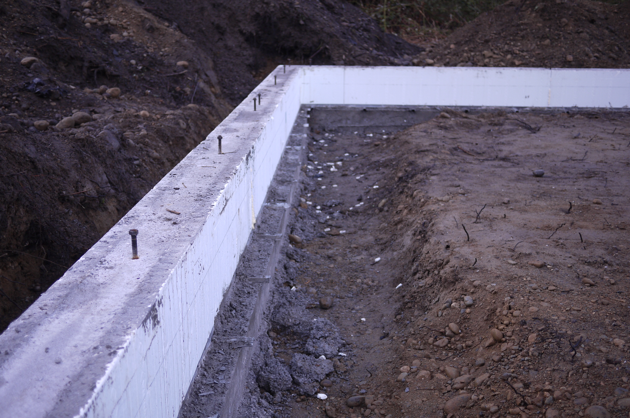
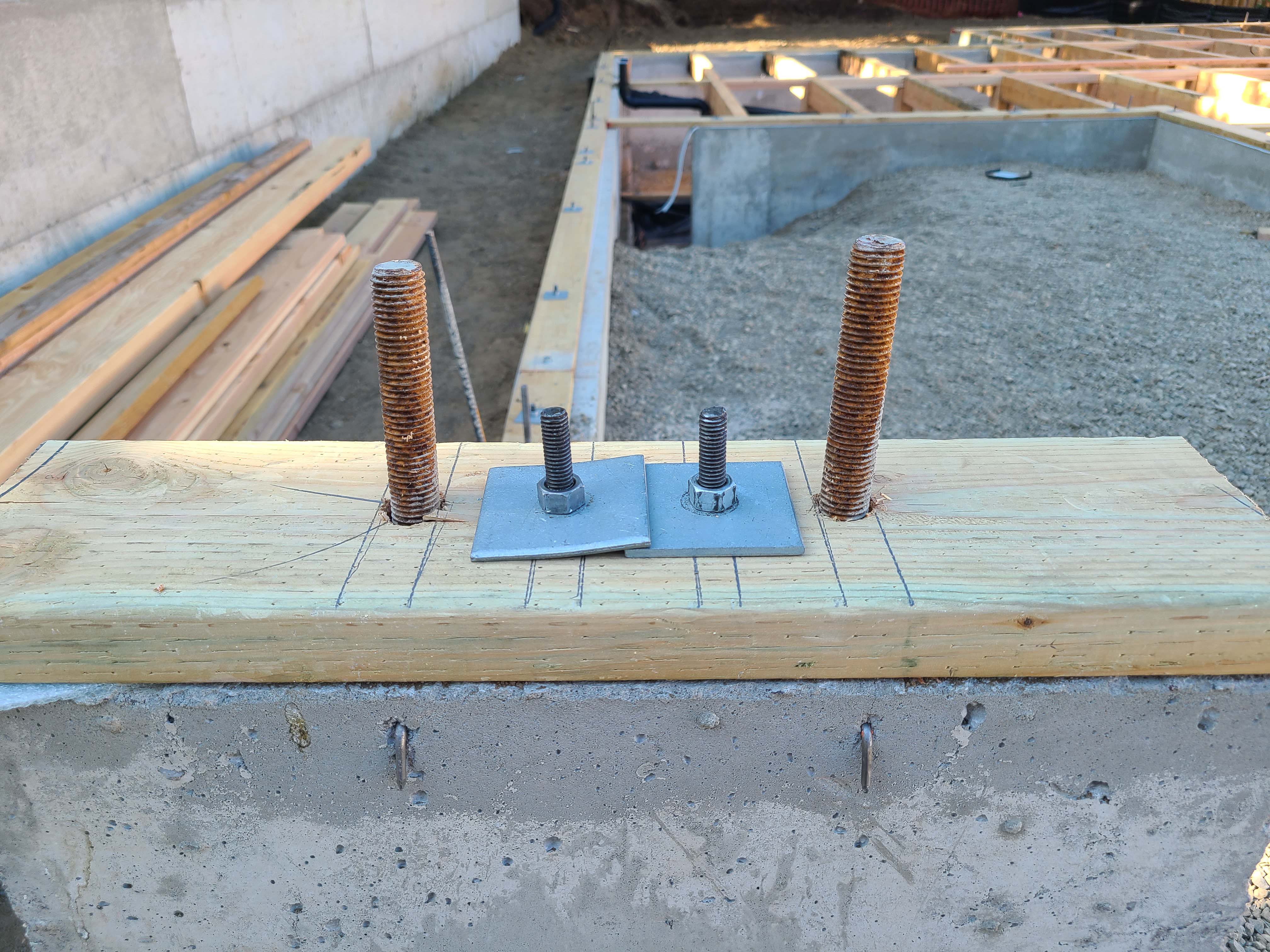
The home’s walls should be connected to its foundations by means of anchor bolts or approved connectors that connect the sill plates to the foundation as required by code (See Figure 1). Attaching the exterior wall sheathing to the sill plates (as shown in Figures 1, 2, 3, 4, and 6 below) will further strengthen the attachment of the walls to the slab foundation. According to the International Residential Code (IRC), anchor bolts should be at least ½-inch diameter and should be embedded at least 7 inches into the foundation concrete. They should be spaced no more than 6 feet apart. Any wall section over 24 inches long should have at least two bolts, located at least 3.5 inches but no more than 12 inches from the ends of the sill plate. Every bolt should have a tightened nut and washer. See the Compliance tab and the IRC for more details. Local code requirements may vary. Consult your local code, a code official, and/or a licensed architect or engineer when designing and constructing for seismic resistance.
Connection of Building to Slab-on-grade Foundation
The following illustrations show five options for connecting and insulating an exterior wall where it attaches to a slab foundation with a turn-down footing. Consult a licensed architect or engineer for guidance for your specific project.
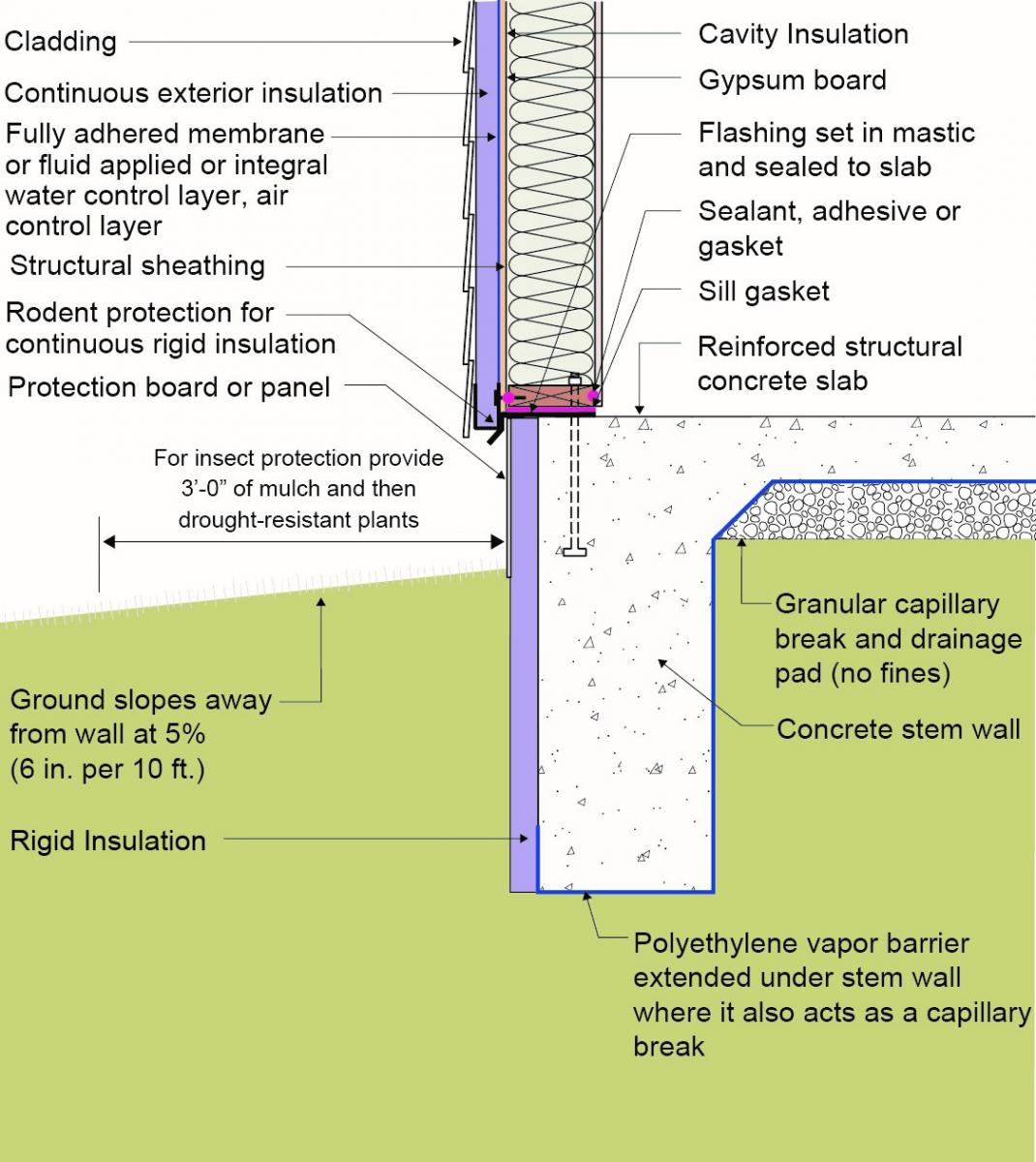
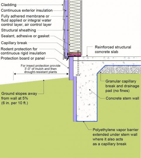
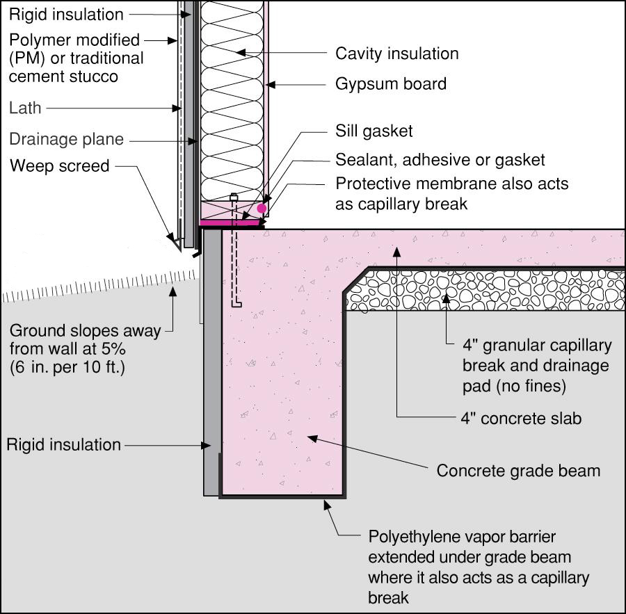
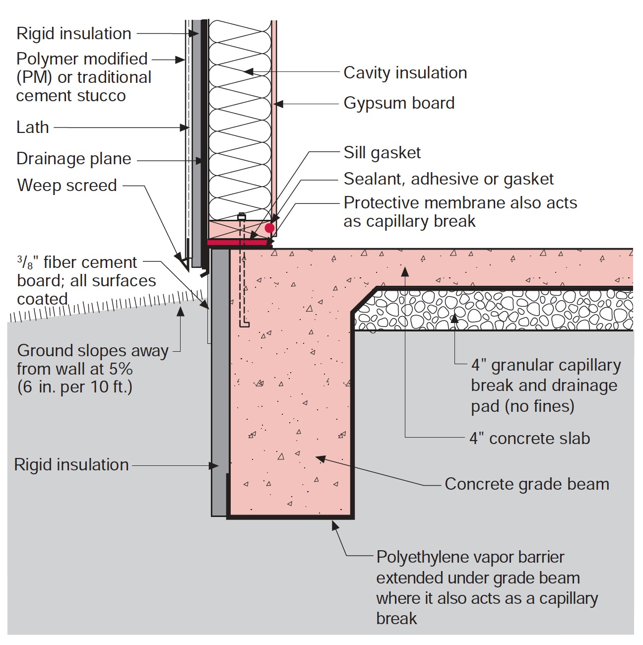
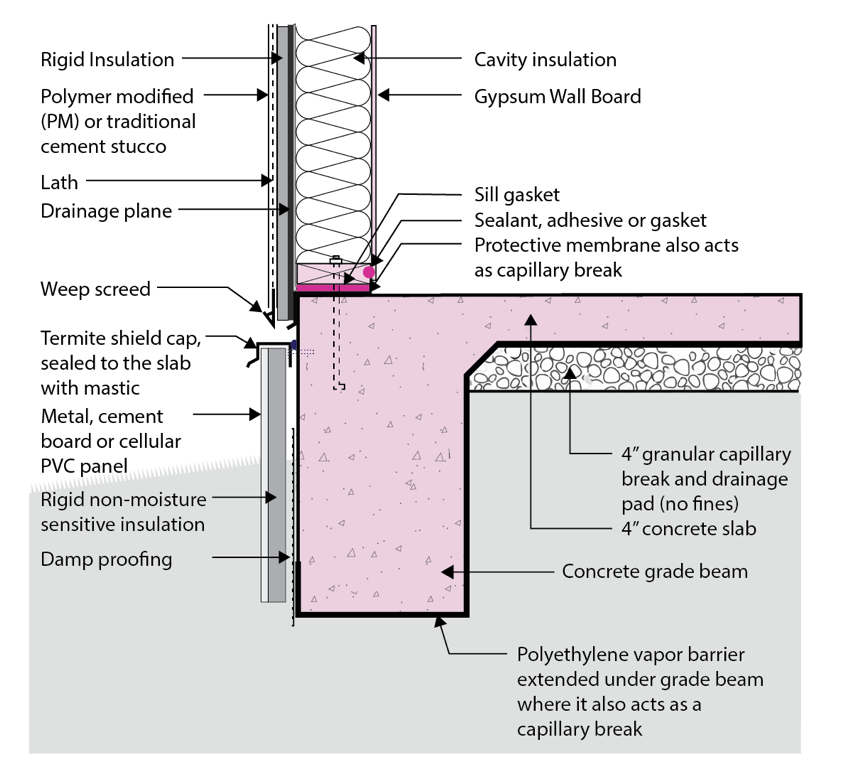
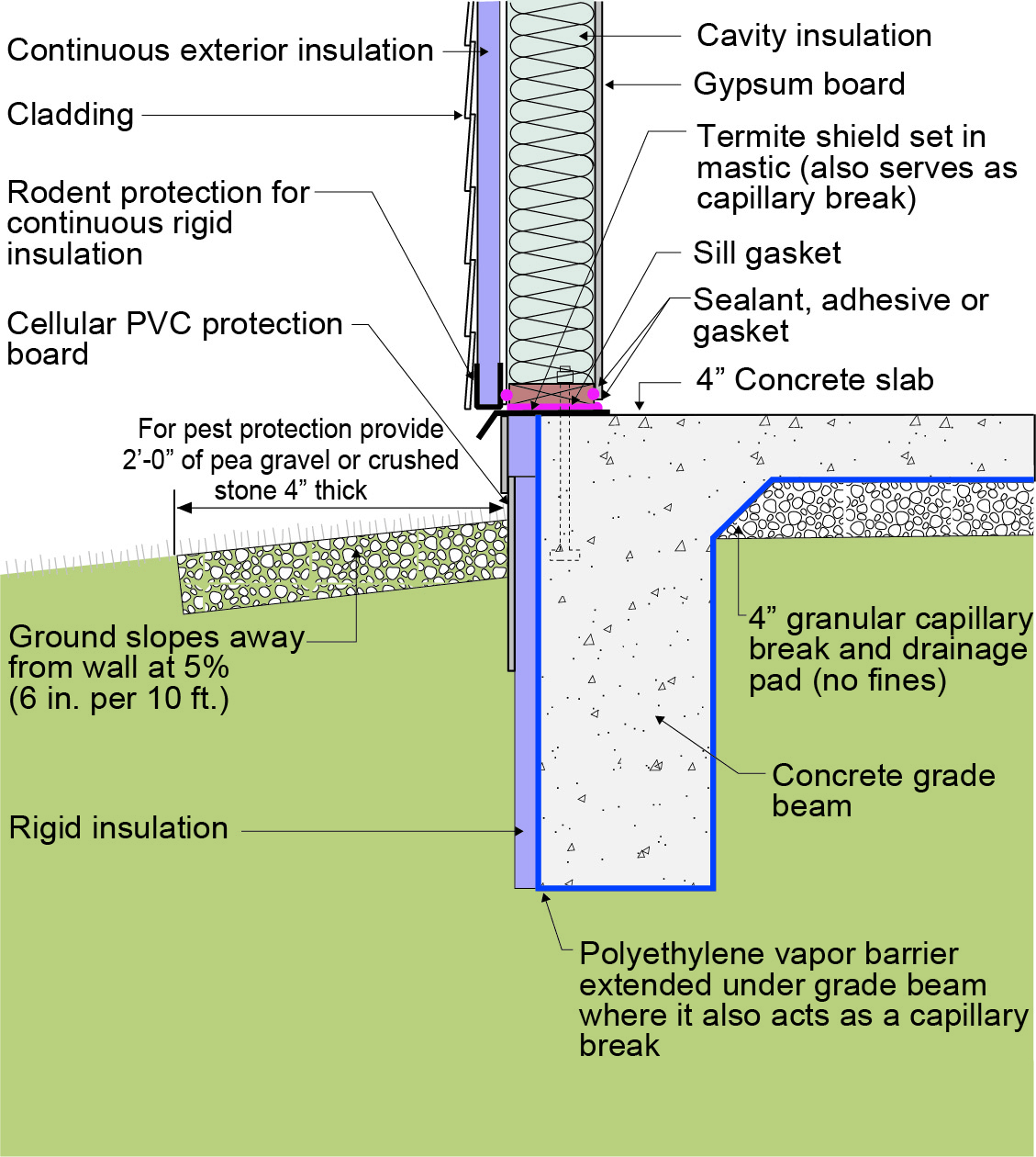
Figure 2 illustrates a concrete slab-on-grade foundation with a turn-down footing that is insulated along the exterior edge of the slab. Note the connection of the continuous exterior structural wood sheathing (plywood or oriented strand board “OSB”) on the exterior wall framing to the frame wall’s bottom plate. Further, note the connection of the frame wall bottom plate to the concrete slab-on-grade foundation by means of an anchor bolt. In this manner, the wall is connected to the foundation diaphragm. Building bracing is provided by the use of the continuous exterior structural wood sheathing (plywood or OSB) in this and the following cases.

Figure 3 illustrates a concrete slab-on-grade foundation with a turn-down footing that is insulated on its top surface. Note the connection of the exterior wall’s structural wood sheathing (plywood or OSB) to the bottom plate as well as to the bearing plate (via attachment to the subfloor). The frame wall bottom plate is connected to the foundation via the anchor bolt. According to the IRC, interior bearing wall sole plates that are not part of a braced wall panel shall be positively anchored with approved fasteners (IRC R403.1.6). In Seismic Design Categories C, D0, D1, and D2, interior braced wall plates and interior bearing wall sole plates shall have anchor bolts spaced not more than 6 feet on center and within 12 inches of the ends of each plate section where supported on a continuous foundation (see IRC R403.1.6.1 for more information).
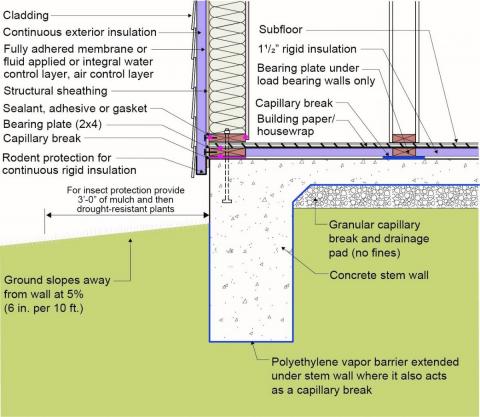
Figure 4 illustrates a similar approach to Figure 3 but with a brick veneer. Note the “seat” in the slab edge for the brick veneer. Two-piece structural brick ties would be used to connect the brick veneer to the exterior frame wall.
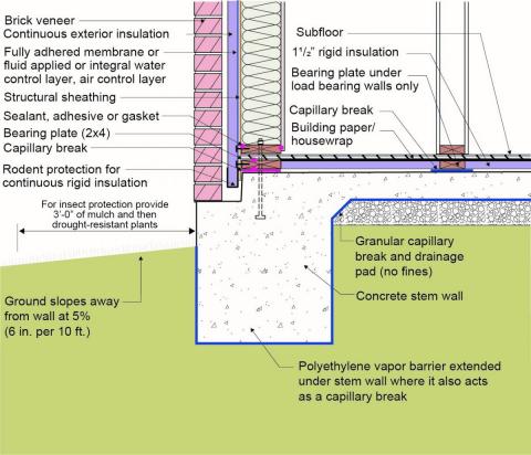
Figure 5 is a modification of Figure 4 and illustrates a concrete slab-on-grade foundation with a turn-down footing and slab edge foundation where the brick veneer is supported by a concrete stem wall that is thermally broken from the slab-on-grade foundation. The stem wall is connected through the external slab edge insulation with fiberglass ties. Note the connection of the continuous exterior wall structural wood sheathing (plywood or OSB) to the frame wall bottom plate and the connection of the bottom plate to the concrete slab via the anchor bolt. Also, note the use of two-piece structural brick ties connecting the brick veneer to the exterior frame wall. Building bracing is provided by continuous exterior structural wood sheathing (plywood or OSB).
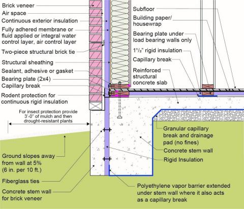
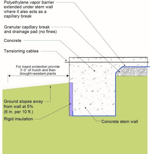
Figure 6 and Figure 7 illustrate a post-tensioned concrete slab-on-grade foundation with a turn-down footing that is insulated along the exterior slab edge. In Figure 7, note the connection of the exterior wall’s structural wood sheathing (plywood or OSB) to the bottom plate and the bottom plate’s connection to the slab-on-grade foundation. Again, in this manner, the wall is connected to the slab foundation diaphragm.
Thermal Efficiency
Slab foundations in new and existing homes should be insulated to be thermally efficient, as required by code. The basis of thermal efficiency is environmental separation, which is provided in the home’s wall and foundation assemblies by continuous air, vapor, thermal, rainwater, and groundwater control layers.
All of the foundations depicted above show a continuous air and rainwater control layer that is attached to the exterior face of the structural sheathing on the walls to control air and rainwater entry. This air and water control layer could consist of house wrap, a fluid-applied barrier product, or a fully adhered membrane.
Vapor control of the walls is provided by controlling the temperature of the wall assembly’s condensing surface by installing continuous exterior insulation. Vapor control of the concrete slab is provided by installing sheet polyethylene under the concrete foundation, wrapping the sheeting under the turn-down footing, and extending it up to grade on the exterior of the footing.
Thermal control is provided by installing continuous exterior insulation and cavity insulation on and in the wall framing. Additionally, rigid insulation is installed either on the exterior edge of the slab (as shown in Figures 2, 5, 6, and 7) or on the top surface of the slab (as shown in Figures 3, 4, and 5).
These approaches work in all climates.
Ensuring Success
Consult a licensed architect or engineer to develop a detailed design and approach for the home to withstand seismic activity. Thermal efficiency should be incorporated as required by code.
Region
Earthquake Areas
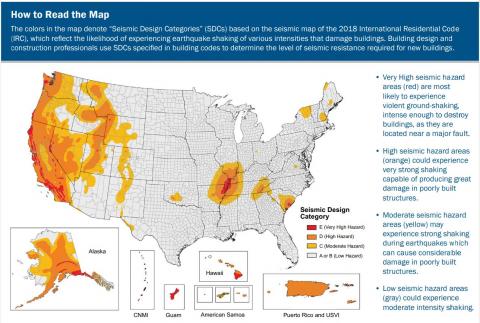
The approaches to seismic control will work in all climates. However, check local building codes for specific requirements as seismic risk and requirements vary based on location; see map below. Insulation requirements for thermal efficiency are climate dependent; see the Compliance tab and consult local code for requirements.
The International Residential Code (IRC) takes a building’s seismic risk into account based on location. The IRC contours the United States into seismic design categories, from low risk to high risk as shown in Figure 1, which designates the categories by letter: A, B, C, D0, D1, D2, and E, with A designating the lowest risk and E designating areas with the highest risk. The IRC has design guidelines for categories A through D2 as well as scenarios for when a building in design category E can be reassigned to category D2. If a building located in design category E cannot be reassigned to category D2 then it must be designed using the International Building Code (IBC), not the IRC.
Training
Right and Wrong Images
Source
Guidebook providing useful examples of high performance retrofit techniques for the building enclosure of wood frame residential construction in a cold and somewhat wet climate.
Source
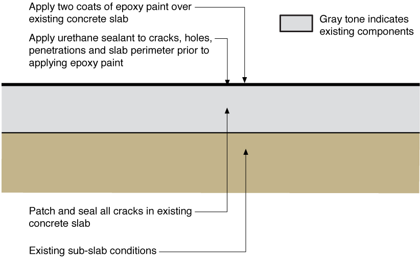
Information sheet about insulating slabs.
Source
Source
Source
Source
Source
Videos

Compliance
More Info
References and Resources
*For non-dated media, such as websites, the date listed is the date accessed.
Contributors to this Guide
The following authors and organizations contributed to the content in this Guide.
Building Science Corporation
Pacific Northwest National Laboratory
Questions? Comments? Contact our webmaster.