
Scope

Design and construct or retrofit roof assemblies to resist wind pressures at roof edges during high-wind events.

  • Install a fully adhered roof membrane over the entire surface area of the roof deck.
  • Install code-compliant metal drip edges at eaves and gables/rakes. 
  • Secure cladding at roof edges.
    • Install asphalt shingles at eaves over an asphalt shingle starter strip that is adhered to the fully adhered membrane underlayment or the drip edge or both. Set asphalt shingles that are installed at eaves and at gables and rakes in a minimum 8-inch wide strip of flashing cement.
    • Install metal roof cladding over a “slip sheet” installed between the metal roof and the fully adhered membrane. Also, use a continuous cleat to mechanically attach the metal roofing.

See the Compliance Tab for links to related codes and standards and voluntary federal energy-efficiency program requirements.

Description

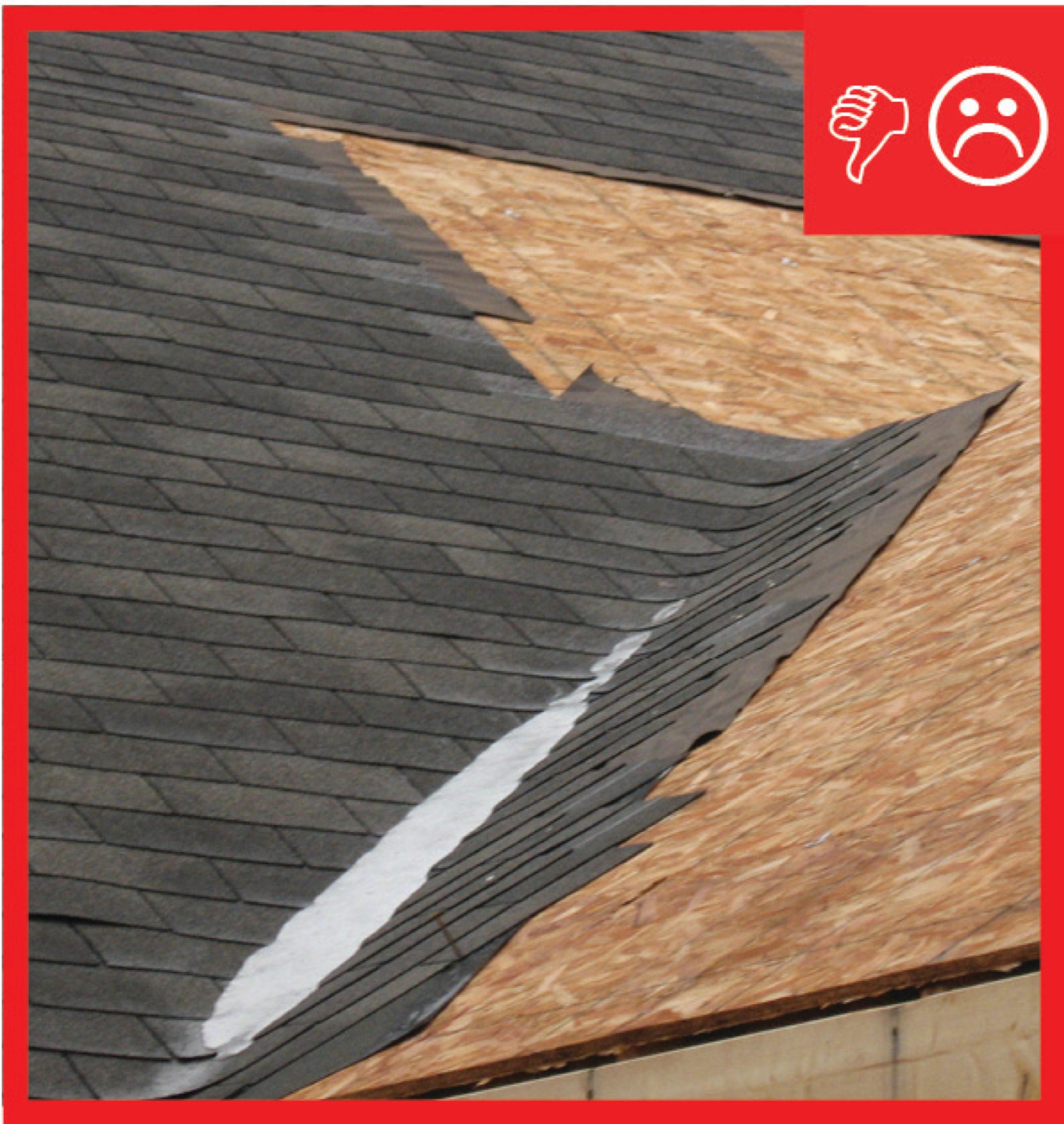
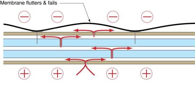
The greatest stress roof assemblies experience in high wind zones is at roof edges. That is where roofs experience the highest positive and negative air pressures. Roof assemblies need to be able to resist the wind pressures that can act on them during high wind events such as hurricanes. In addition to the highest wind pressure differences, roof edges can also experience the greatest rainwater loads. In sloping roofs, all of the rainwater incident on the roof area drains downward to the roof edge.

This guide provides guidance for the construction of roof edges in sloping roof assemblies for residential construction. The guidance is applicable to both new construction and the re-roofing of existing roof assemblies.

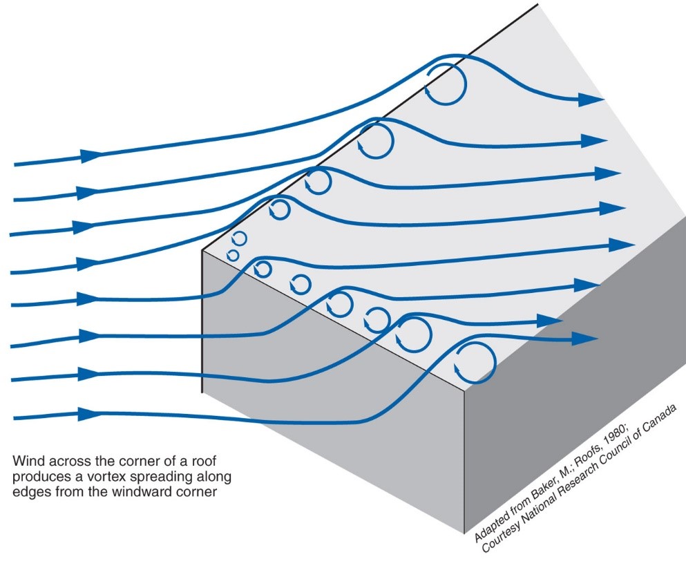
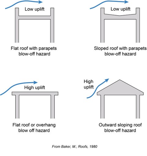
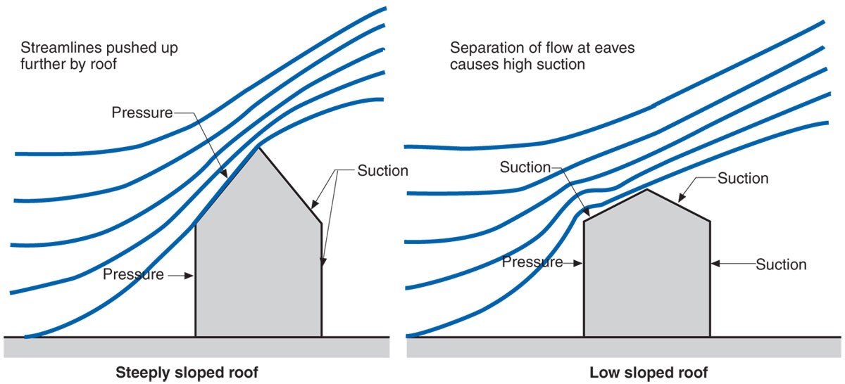
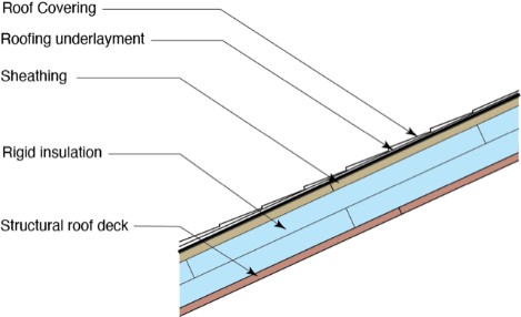
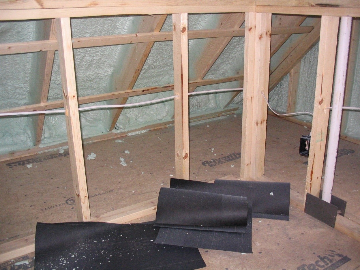
During high-wind events, high localized areas of negative pressure (“suction”) occur above roof edges due to the development of vortices (Figure 1). These pressures become more pronounced with sloping roofs typical of residential construction (Figure 2 and Figure 3). Most roof covering “blow-off” occurs at roof edges for these reasons.

During high wind events, vortices form along the edges of the roof creating areas of localized negative pressure ('suction') above the roof.
Figure 1. During high-wind events, vortices form along the edges of the roof creating areas of localized negative pressure ('suction') above the roof. (Source: Building Science Corporation.)


During high wind events, sloped roofs and flat roofs experience higher uplift forces than flat roofs with parapets.
Figure 2. During high wind events, sloped roofs and flat roofs experience higher uplift forces than flat roofs with parapets. (Source: Building Science Corporation.)


Strong wind passing over a sloped roof cause positive pressure on windward side and negative pressure on leeward side and at vortices above windward eave.
Figure 3. As wind passes over a steep sloped roof, it generally pushes on the near side and pulls on the far side of the roof but separation of flow at the eaves can cause areas of high negative pressure, or suction, at the near side above the eave. (Source: Building Science Corporation.)


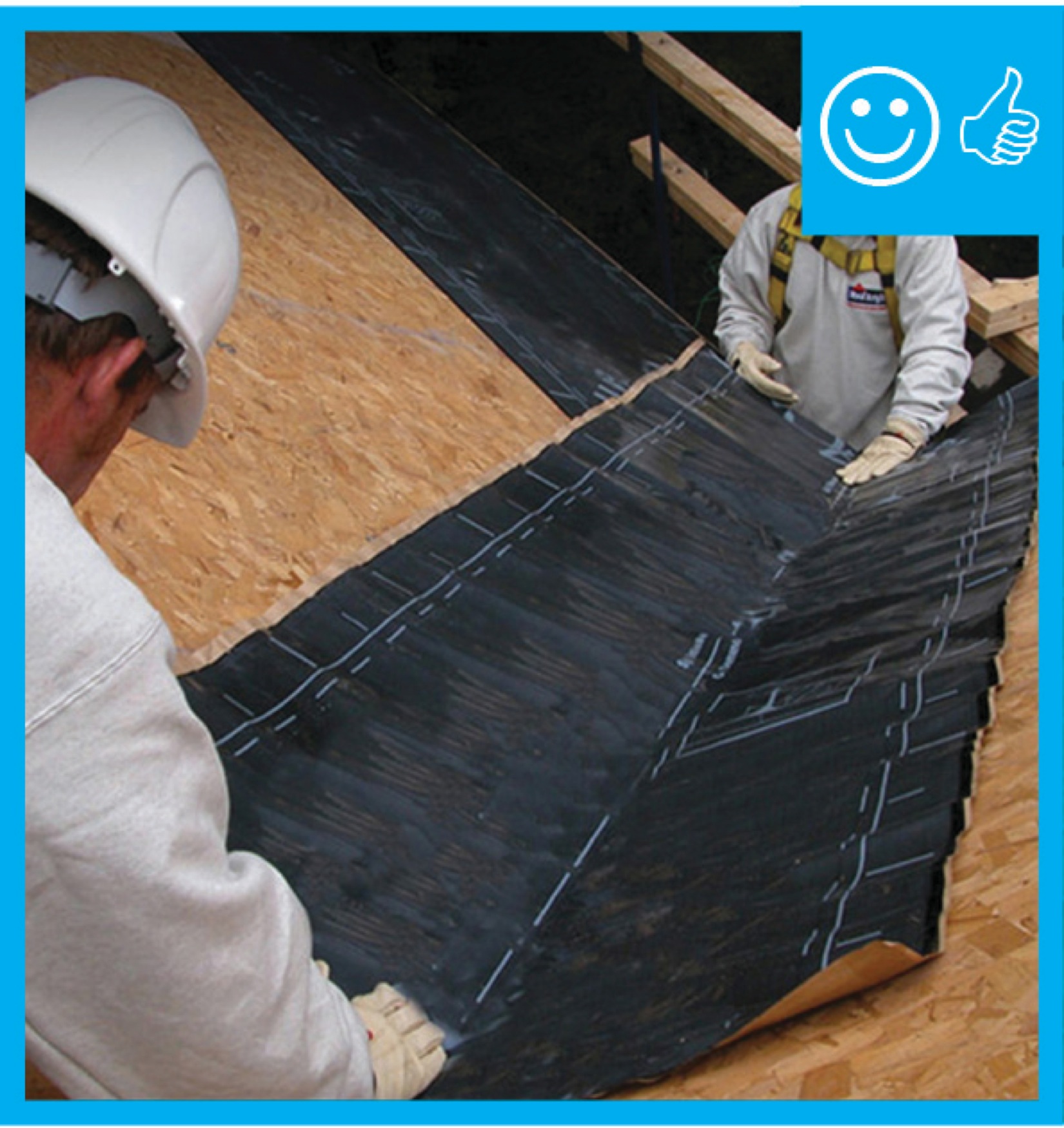
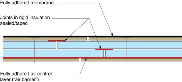
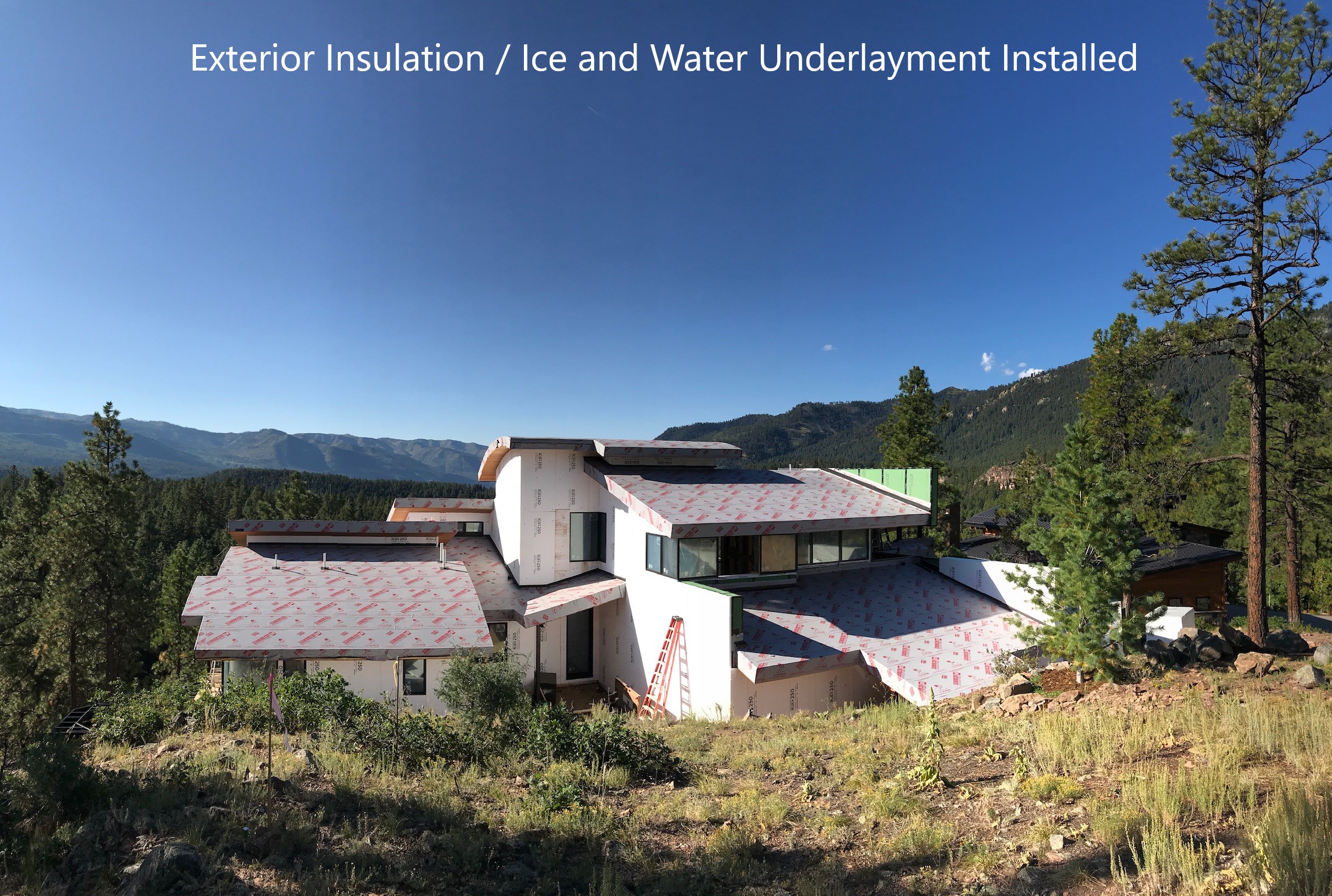
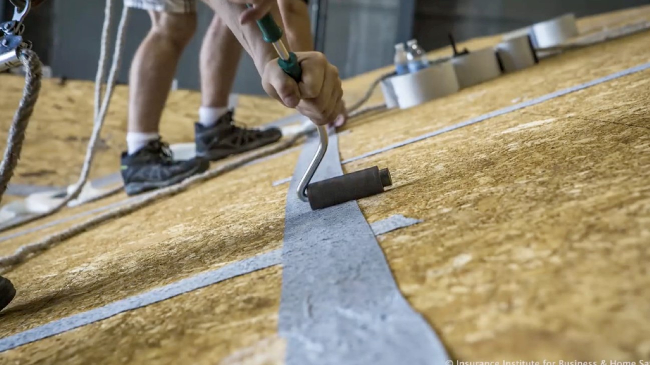
In high-wind zones it is recommended – as a minimum requirement - that a fully adhered roof membrane underlayment be installed at roof eaves and roof rakes. This could be a single-ply membrane such as TPO, EPDM, or PVC, or a built-up modified bitumen, or fluid-applied membrane. Improved performance and reduced risk occurs if a fully adhered roof membrane underlayment is installed over the entire surface area of the roof deck – not just at roof eaves and roof rakes. 

If a fully adhered roof membrane is not installed over the entire surface area of the roof deck, and a mechanically fastened underlayment is installed instead, alternative roof deck air sealing and water control requirements are necessary to provide acceptable performance and acceptable risk in high wind zones. Alternative roof deck air sealing and water control requirements can be found in the Insurance Institute for Building and Home Safety (IBHS) Fortified Home Hurricane Technical Summary.

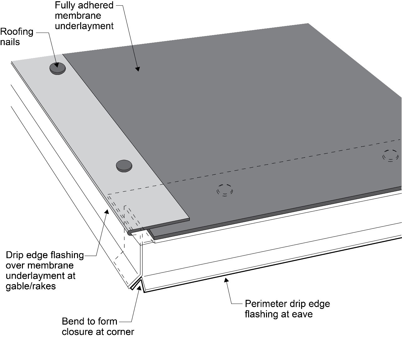
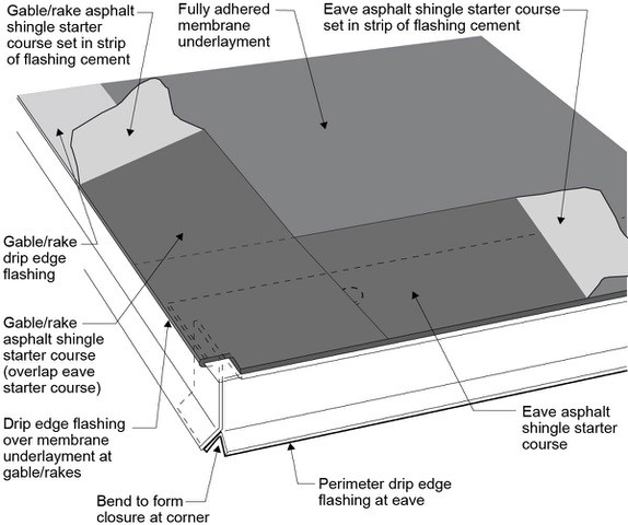
In high-wind zones, it is recommended that drip edges be installed at roof eaves and roof rakes (Figure 4). The following drip edge installation requirements are recommended:

  • Code compliant metal drip edges should be installed at eaves and gables or rakes (applicable codes set the minimum gauge required).
  • Drip edges should overlap a minimum of 3 inches at joints.
  • Eave drip edges should extend a minimum of ½ inch below sheathing and overlap the top of the roof sheathing edge a minimum of 2 inches.
  • The drip edge should be mechanically fastened to the roof deck at a maximum spacing of 4 inches and the fasteners should be compatible with the flashing.
  • Drip edges at eaves can be installed over the fully adhered membrane underlayment if flashing cement is used to seal the edges.
  • Drip edges at gables or rakes should be installed over the fully adhered membrane underlayment.
Right – Install metal drip edge at roof edges in high wind and rain areas.
Figure 4. In high-wind zones, metal drip edge should be installed at roof eaves and roof rakes. (Source: Building Science Corporation.)


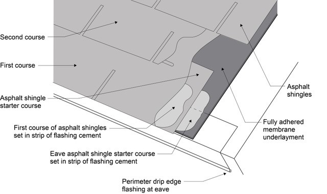
Asphalt shingles that are installed at eaves and gables or rakes should be installed over an asphalt shingle starter strip that is set in a minimum 8-inch-wide strip of flashing cement adhered to the fully adhered membrane underlayment and/or to the drip edge (Figure 5). Asphalt shingle courses are then installed over the starter course (Figure 6).

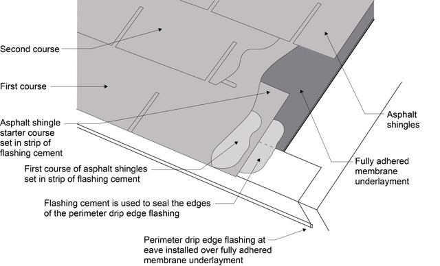
Where drip edge flashing is installed over the fully adhered membrane at the eaves, flashing cement should be used to seal the upper drip edge of the flashing (Figure 7).

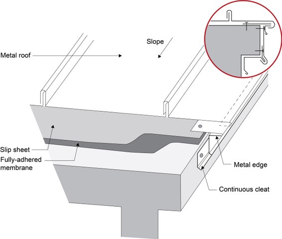
With metal roof assemblies, the approach is modified to include a “slip sheet” (typically a loose laid building paper) between the metal roof and the fully adhered membrane. The function of the “slip sheet” is to account for the significant movement that metal roof assemblies experience due to temperature changes over the course of a day, week, or season. Additionally, a continuous cleat is necessary to mechanically attach the metal roofing (Figure 8).

Right – Start asphalt shingle installation with a starter strip set in an 8-inch strip of flashing cement.
Figure 5. Start asphalt shingle installation with a starter strip set in an 8-inch strip of flashing cement. (Source: Building Science Corporation.)


Right – Install asphalt shingles over a starter strip set in an 8-inch strip of flashing cement.
Figure 6. Install asphalt shingle courses over the starter course which is set in flashing cement. (Source: Building Science Corporation.)


Right – If drip edge flashing is installed over fully adhered roof membrane at eaves, use flashing cement to seal the upper edge of the flashing.
Figure 7. If drip edge flashing is installed over fully adhered roof membrane at the eaves, use flashing cement to seal the upper edge of the flashing. (Source: Building Science Corporation.)


Right – Under metal roofing, sheathing is protected by metal edging over a fully adhered membrane and a slip sheet of loose laid building paper.
Figure 8. Under metal roofing, sheathing is protected by metal edging over a fully adhered membrane and a slip sheet of loose laid building paper. (Source: Building Science Corporation.)


Ensuring Success

In high wind zones it is recommended – as a minimum requirement - that a fully adhered roof membrane underlayment be installed at roof eaves and roof rakes.

Asphalt shingles that are installed at eaves should be installed over an asphalt shingle starter strip that is adhered to the fully adhered membrane underlayment, or to the drip edge, or both.

Asphalt shingles that are installed at gables/rakes should be installed set in a minimum 8-inch-wide strip of flashing cement.

Region

IBHS Fortified Home Hurricane and High Wind Standards

Drip Edge

Drip edge must be installed (at eaves and rakes) with 3-in. laps. Drip edge shall extend ½ in. below sheathing and extend back on the roof a minimum of 2 in. Drip edge at eaves and at gable ends shall be installed over the underlayment. The drip edge shall be mechanically fastened to the roof deck at a maximum of 4 in. on center.  Note: For shingle roofs, starter strips must be adhered at the eave and rake. Either embed the starter strip in roofing cement or use self-adhered starter strips

Training

Right and Wrong Images

Right – Install metal drip edge at roof edges in high wind and rain areas
Source
Courtesy Of
BSC
Right – If drip edge flashing is installed over fully adhered roof membrane at eaves, use flashing cement to seal the upper edge of the flashing
Source
Courtesy Of
BSC
Right – Under metal roofing, sheathing is protected by metal edging over a fully adhered membrane and a slip sheet of loose laid building paper
Source
Courtesy Of
BSC
Wrong – The roof sheathing was inadequately fastened and gave way causing the gable end wall to fail
Source
Author(s)
Insurance Institute for Business and Home Safety
Organization(s)
IBHS
Description

Guide describing the requirements by  FORTIFIED Home™ for improving the home's resistance in severe thunderstorms, straight-line wind events, and high winds at the outer edges of tornadoes.

Right – There is a self-sealing bituminous membrane installed at the valley of the roof prior to the roof felt
Source
Author(s)
U.S. Environmental Protection Agency,
ENERGY STAR
Organization(s)
EPA,
ENERGY STAR
Description

Guide describing details that serve as a visual reference for each of the line items in the Water Management System Builder Checklist.

Wrong – There is not a self-sealing bituminous membrane installed at the valley of the roof
Source
Author(s)
U.S. Environmental Protection Agency,
ENERGY STAR
Organization(s)
EPA,
ENERGY STAR
Description

Guide describing details that serve as a visual reference for each of the line items in the Water Management System Builder Checklist.

Right – The roof membrane is fully adhered and deck seams are sealed so the membrane will not flutter and fail due to negative pressure from high winds
Source
Courtesy Of
BSC
Wrong – This roof membrane on a low slope roof is fluttering and may fail because it is not fully adhered and deck seams below are not sealed, allowing air to leak up into the assembly while the membrane is pulled up due to negative pressures from wind
Source
Courtesy Of
BSC
Right – A fully adhered roof membrane provides thorough water and wind protection in this mountain top location.
Source
Wrong – If roof membrane is not fully adhered, it can flutter and fail due to negative pressure from wind above and positive pressure from air leakage through roof deck below
Source
Courtesy Of
BSC
Wrong – Roof underlayment is not fully adhered and roof deck seams are not sealed so roof is susceptible to high-wind events
Source
Courtesy Of
BSC
Right – Roof underlayment is fully adhered and roof deck seams are sealed so roof is resistant to high-wind events
Source
Courtesy Of
BSC
Right – Under metal roofing, sheathing is protected by metal edging over a fully adhered membrane and a slip sheet of loose laid building paper
Source
Courtesy Of
BSC
Right – A roller helps the tape to adhere over seams in the deck sheathing
Source
Courtesy Of
BSC
Right - Metal drip edge on this south Florida CMU home protects the top of the fascia and edge of the roof deck from water, wind-blown rain and embers, and insects.
Source
Right - An unvented attic with no soffit vents, borate-treated fascia board, metal drip edge, and concrete block construction on this south Florida home help make it resistant to hurricanes, pests, and wind-born wildfire embers.
Source
Right – This hot-humid climate home employs several hurricane- and termite-resistant features including concrete block construction, borate-treated framing, a hip roof design with metal drip edge, impact-rated windows, and an unvented attic.
Source

Videos

Publication Date
·
Author(s)
Guertin Mike
·
Organization(s)
Fine Homebuilding Magazine
Description
Video presentation explaining proper roof membrane and shingle installation, including key weak points where moisture can get in during a disaster weather event.

CAD Files

IBHS Fortified Home Drip Edge Installation for Hurricanes
Download: PDF
IBHS Fortified Home Drip Edge Installation for Concrete and Clay Tile Roofs
Download: PDF
IBHS Fortified Home Drip Edge Installation for High Winds
Download: PDF
IBHS Fortified Home Self-Adhered Membrane Roof Deck
Download: PDF

More Info

References and Resources

Publication Date
·
Author(s)
Insurance Institute for Business and Home Safety
·
Organization(s)
IBHS
Description
Website providing technical documents of checklists, calculators, bulletin, modular home toolkit, standard details, and corrosion resistance requirements – map set; describing the requirements of the IBHS Fortified Home program to improve the disaster resistance of new and existing homes.

*For non-dated media, such as websites, the date listed is the date accessed.

Contributors to this Guide

The following authors and organizations contributed to the content in this Guide.

Building Science Corporation

Last Updated

Questions? Comments? Contact our webmaster.

Disclaimer

This content is a work created with funding provided by the United States Department of Energy under Contract no DE-AC05-076RL01830 for the operation of Pacific Northwest National Laboratory. The information and guidance provided by Pacific Northwest National Laboratory (PNNL) in the content are intended solely for educational purposes only and do not constitute formal training or certification. It is provided with the explicit understanding that neither the United States Government nor the United States Department of Energy, nor the Contractor, nor any or their employees, nor any jurisdiction or organization that has cooperated in the development of these materials, makes any warranty, express or implied, or assumes any legal liability or responsibility for the accuracy, completeness, or usefulness or any information, apparatus, product, software, or process disclosed, or represents that its use would not infringe privately owned rights. Reference herein to any specific commercial product, process, or service by trade name, trademark, manufacturer, or otherwise does not constitute or imply its endorsement, recommendation, or favoring by the United States Government or any agency thereof, or Battelle Memorial Institute. The views and opinions of authors expressed herein do not necessarily state or reflect those of the United States Government or any agency thereof. Viewers assumes full responsibility for all actions that they may take from information provided in this content including ensuring the safety, code compliance, and proper functionality of any products they choose to install. Installation and use of such products should be performed in accordance with local regulations and manufacturer instructions.