

Scope
Install a mounting system for solar thermal or solar photovoltaic panels.
- Consider the roof type (material and slope), weatherproofing, installation convenience, and wind and snow loadings.
- Choose an appropriate racking and mounting system for the type of PV module, and install the system along with needed flashing and seals.
See the Compliance Tab for links to related codes and standards and voluntary federal energy-efficiency program requirements.
Description
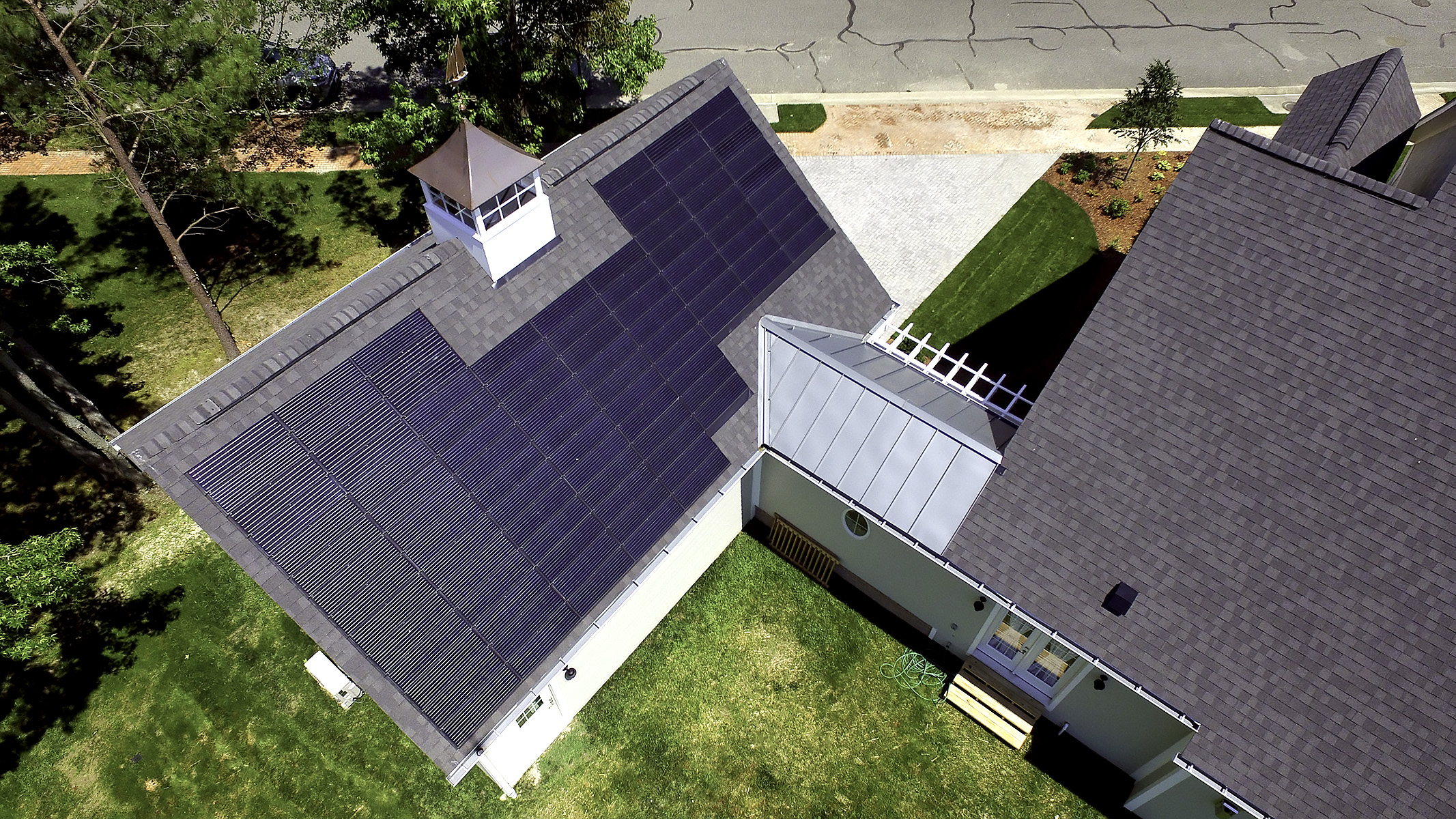
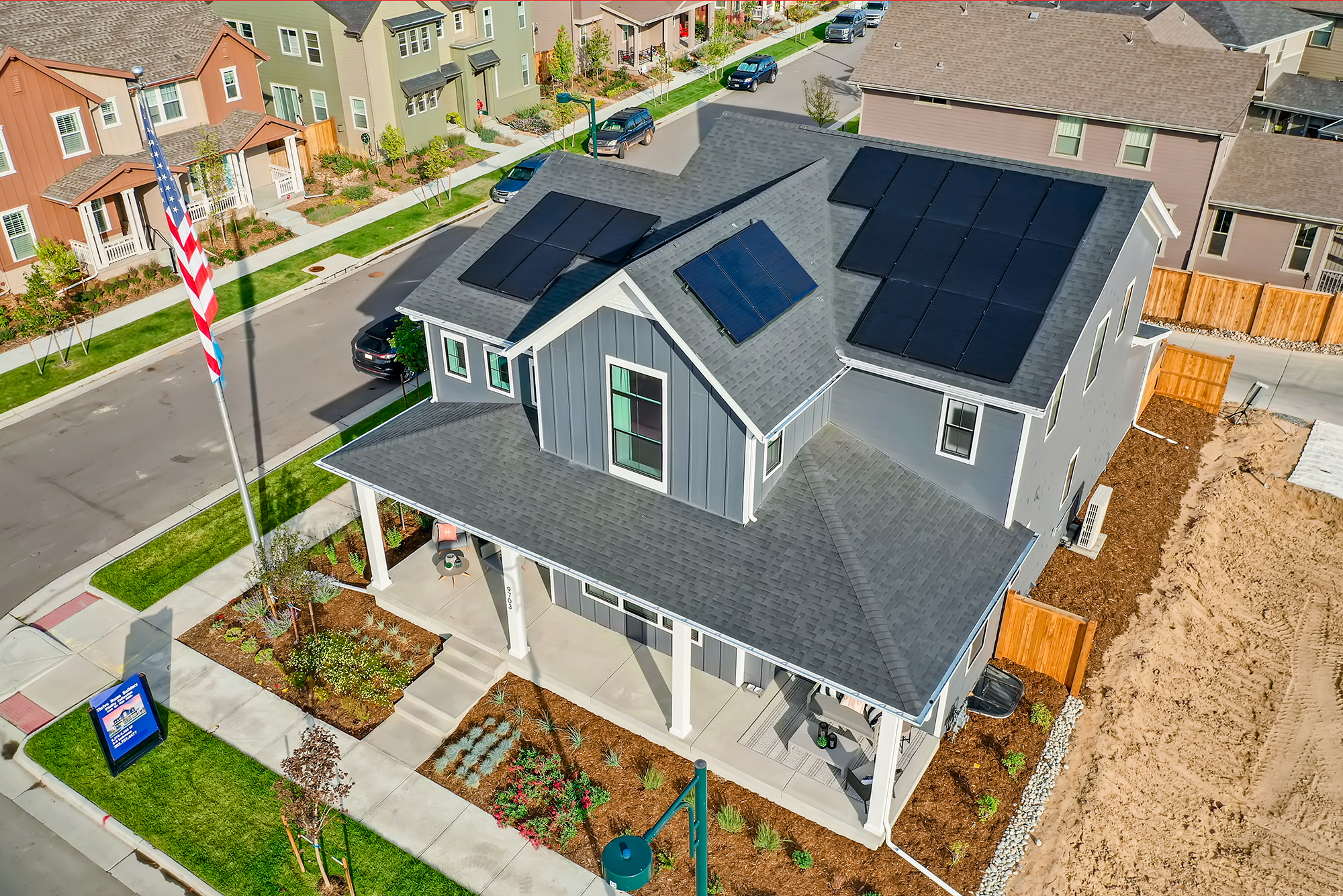
Photovoltaics (PV) are becoming more common today on the rooftops of homes to capture and convert solar energy into electricity, thereby reducing total energy costs for the homeowner. These may be large PV panels that are assembled into an array or PV shingles that are used in place of standard roofing shingles. Solar thermal systems for heating water are installed on the roof in the same way the PV panels are installed.
When adding any type of solar array on the roof of a newly constructed house, it is important to choose an appropriate and well-designed racking and mounting system that can provide structural support to the solar modules and to properly flash the mounting blocks and integrate the flashing with the roof underlayment and roof covering to ensure the integrity of the roof.
Several types of roof racking and mounting systems are available on the market by various manufacturers. Although each manufacturer has its own uniquely designed mechanisms, the systems generally have the same basic components. For PV modules, the racking and mounting system typically consists of the following: a two-railed track that is bolted into the rafters and onto which the panels are clamped, a flashing component for weatherproofing the penetrations, and all required hardware such as bolts and clamps. Some systems eliminate the need for the rails, thereby removing those additional connections. If integrated roof modules (e.g., PV shingles) are installed, no additional mounting system is needed. Photovoltaic shingles can be fastened directly to the roof deck like standard roofing shingles. This installation typically takes place when the roof covering is being installed and would require only one roofing contractor who is experienced in installing PV shingles.
Another factor is whether the roof slope will be suitable for the PV modules or if additional slope needs to be added via the roof mount system.
The PV panel layout must also address the requirements of IRC Section 324 Solar Energy Systems. These requirements specify firefighter access to the ridge with a 36-inch-wide clear path for the full length of the ridge and two paths from the eave to the ridge as well as a 36-inch-wide clear path from the eave to any egress windows that open to the roof; plumbing vent locations; structural requirements; and roof penetrations. See the Compliance tab for additional code-related details.
When choosing a rack and mounting system, factors such as the roof material, roof slope, weatherproofing, installation convenience, and wind and snow loads should be taken into account. Certain mounting systems may be specific to particular roofing materials or slopes or may be able to function with all roof types. Masonry roofs may require additional structural considerations because of the extra weight of the roof tiles.
Roof Penetrations, Flashing, and Roof Attachments
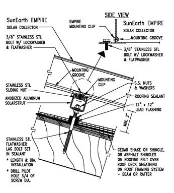
With the exception of raised-seam metal roofs, most roof types require penetrations for rack mounts. In the best installations, standoffs, lag screws, or bolts tie into structural members. All brackets should have butyl tape or a high-quality caulking such as polyurethane or polysulfide, to seal any bolt penetrations and under struts, brackets, or mounting feet.
If standoff mounts or other brackets can be installed before the roofers install the finished roof, roofers can more easily shingle or tile around the flashing and may install the flashing for the mounts. This approach helps to ensure that the roof warranty is intact. Solar installers need to coordinate with roofers prior to the installation to ensure warranty issues are addressed, proper flashing materials are on hand, and installation procedures have been worked out.
Weatherproofing is an extremely important element of a PV anchoring system. Because many penetrations will be made in the roof to secure the mounting system, it is critical to ensure that leaks do not develop from those penetrations. In the past, sealants alone were used to waterproof the penetrations, but this became problematic because the sealant often would break down from the impacts of the ultraviolet rays from the sun, oxidation, expansion and contraction, and wind and other vibrations. Therefore, a better practice is to have additional weatherproofing in place, including flashing. The IRC now specifically requires that roof penetrations for rooftop PV systems be flashed and sealed. See the guides Flashing of Penetrations in Existing Roofs and Roof Deck Valleys and Penetrations Sealed for flashing details for roof penetrations.
Wind Loads
There are two structural concerns: dead load, the weight of the systems bearing on the roof, and live loads, the intermittent loads created by wind, snow, and maintenance people. Collectors should never be supported by roof sheathing between structural members. The project structural engineer or truss designer should be involved early in the design process. Even if not needed to accommodate the load, additional framing may be added as blocking for installing the anchors even if structural loads are within limits. Design wind loads for PV panels and other structures are defined in the American Society for Civil Engineers Minimum Design Loads and Associated Criteria for Buildings and Other Structures, ASCE/SEI 7-16.
Dead loads are typically minimal in PV arrays, no more than 5 to 10 lbs/ft.2 However, the loads are often transferred to the rooftop through mounting devices that concentrate the array dead loads onto small surface areas of the roof or individual load-bearing members. These conditions can significantly add to the loading conditions of a single truss, rafter, joist, decking, or other roof component. Live loads can be large in magnitude, but are intermittent and are attributed to wind, snow, and maintenance personnel. Most PV modules are rated for a dead loading of 50 to 55 lbs/ft2 or equivalent to the pressure of constant 110 to120 mph winds (Barkasi and Dunlop 2001).
Designing mounting systems for wind uplift is more critical in areas subject to hurricanes and excessive wind speeds. Manufacturers of collectors, modules, and mounting systems typically have their mounting systems pre-engineered for worst-case wind loads (DEG 2005). In parts of the world that are vulnerable to hurricanes or extreme wind storms, the collector and its mounting structure need to be able to withstand intermittent wind loads from 115 to180 miles per hour depending on the wind zone in which the home is being built. This corresponds to a pressure of about 75 pounds per square foot (FSEC 2006). Rudin and Becerra (2006) describe approaches for analyzing severe wind loads.
Wind loads may be greater near the roof ridge. Mounting collectors or arrays near the ridge may increase wind loads on the equipment (FSEC 2006). Similarly, locating collectors and arrays in from eaves may reduce wind loads (Rudin and Becerra 2006).
Good engineering cannot make up for poor installation. It is easy to miss structural members when fastening mounting systems to the roof. Care must be taken to ensure that fasteners are correctly positioned. Failure of a bolt to torque down is a clear indication the structural member has been missed. Also, bolts shorter than those recommended by the manufacturer should not be used. Mounting systems can be secured to structural blocking placed between rafters/trusses if the layout of rafters/trusses does not align with the desired collector location. All bolts securing collectors or modules to racks or brackets must be securely tightened. Here are a few things to consider for PV anchoring systems in hurricane-prone regions:
- Specify double-nutting of the panel clamp bolts. For the first nut, specify nuts that are furnished with T-bolts. For the second nut, specify a stainless-steel lock nut with a nylon insert.
- Specify that all bolted connections are made with a calibrated torque wrench and torqued as specified by the PV system manufacturer.
- Specify that PV panels are not installed over roof drains and that walkways are provided to each drain so that drains can be easily checked for debris, and cleaned and maintained as appropriate. (FEMA Rooftop Solar Panel Attachment 2018).
For ensuring success, proper maintenance of the system is also necessary. The property owners or operators should have maintenance staff or a contractor annually check the tightness of the PV array’s bolted connectors with a torque wrench. All the panel clamps should be checked and spot checks should be made for bolts that connect rails to clip angles or posts. (FEMA Rooftop Solar Panel Attachment 2018).
Use a reputable contractor with experience in PV installation to help ensure that the installation is done correctly. Insist that PV installers meet with other trades to work out equipment compatibility, supply, and installations issues. For example:
- Roofers need to know what types of flashing to use, who will be installing it, and when. Roofers also need to know if PV tiles will be used that will replace sections of the roof.
- Trades requiring roof penetrations need to know what areas are off limits for vents or other elements that may shade the PV. This coordination issue was the number one area of difficulty identified by PV installers interviewed for this document.
- PV and solar thermal installers need to know what parts of the roof to use for their systems. Typically the truest southern exposure should go to the PV installation.
- For long-term performance, landscape designers and installers need to keep the southern exposure unobstructed from trees and outbuildings.
- Painters and stucco crews need to take all steps necessary to avoid overspray.
Be sure that the PV panel system is properly grounded.
Composition Shingle Roofs
Many efficiency programs recommend that on existing homes, roofs should have 10 or more years of useful life remaining (see for example the DOE Sustainable Energy Resources for Consumers program).
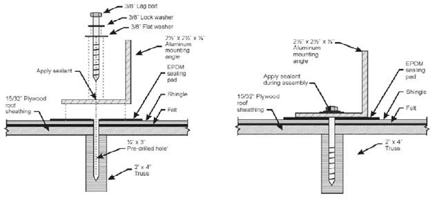
Stanchions and hanger bolts can be used with flashing at the mounting points. In new homes, it is best if both the bolt and the stanchion are applied before the roofing is installed. The lag screw end of the hanger bolt is threaded directly into the structure. The stanchion is lag-screwed to the roof structure (into a truss or rafter). After these are placed, a flashing is applied over the bolt or stanchion. Hanger bolts are preferred due to their low cost and quick installation but should not be used with solar thermal systems that use integrated collector storage for structural reasons. Stanchions may be flashed with roof boot type flashing.
Flat (Low Slope) Roofs
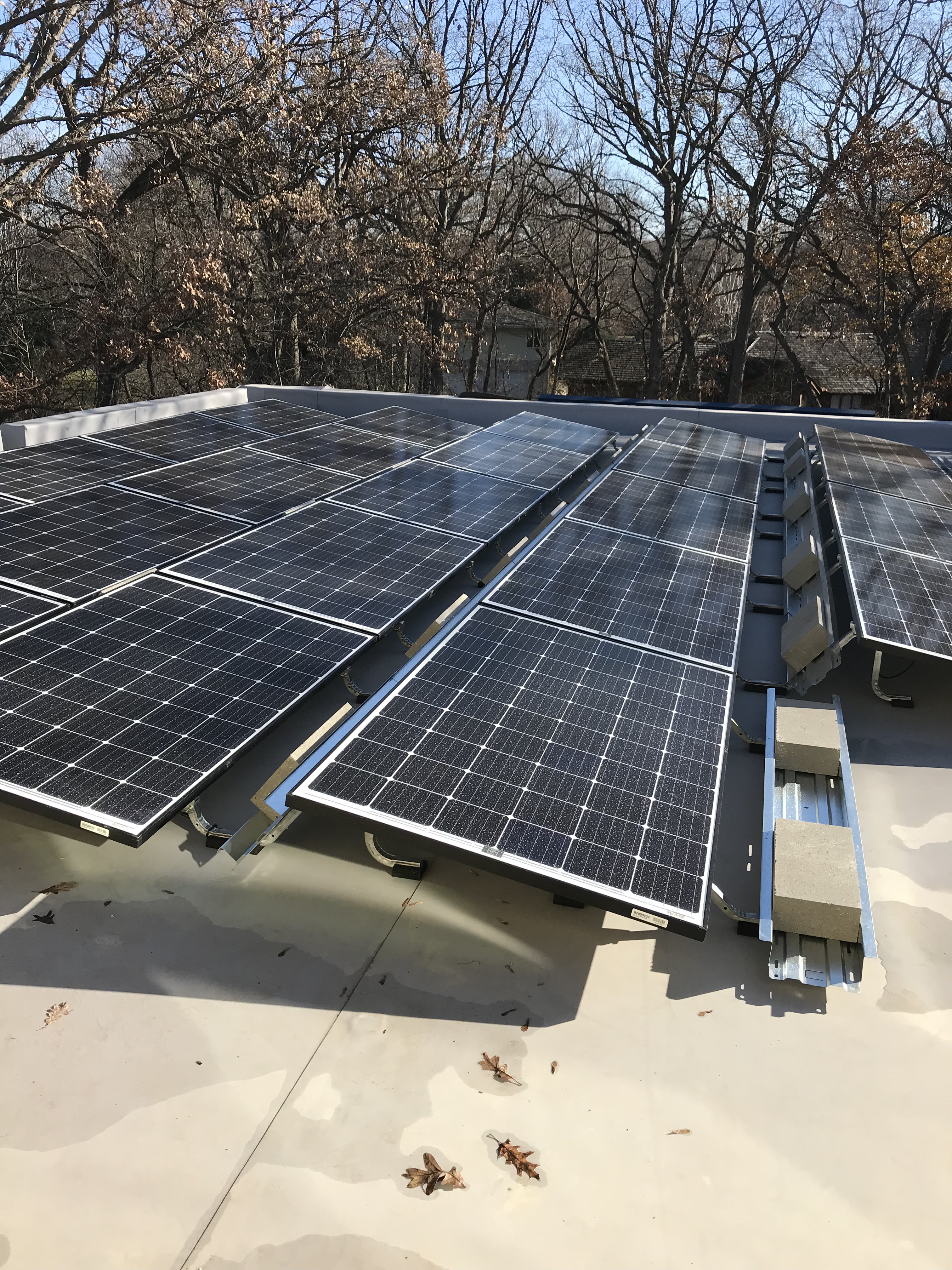
Curb mounts work well for flat or low-slope roofs. Elevated racks are often used on flat roofs to provide an appropriate angle for the collector or module. Racks may be mounted on curbs or standoff mounts. Another reason for using racks in colder climates is to place modules and collectors above snow levels. Curb systems are described in the Roofing and Waterproofing Manual by the National Roofing Contractors Association. To avoid putting penetrations in EPDM roofing membrane found on flat/low-slope roofs, other mounting systems are available, including a system that uses a heat gun to heat weld plastic flanges on the mounting brackets directly to the membrane using standard hot-air welding techniques.
Standing Seam Metal Roofs
Clips can attach to raised seam metal roofing that do not require a roof penetration and can be used to clamp racks to the seam (Christian 2006).
Structural Insulated Panel Roofs
As part of a study of affordable ZEH in Tennessee, a process was worked out for installing racks on roofs made with structural insulated panels (Christian 2006). PV attachment is a potential issue due to the lack of rafter framing in SIPS roofs, requiring attachment solely to OSB sheathing. A more recent article in Home Power describes an approach using a toggle bolt (Sughrue 2013). Follow SIP manufacturers instructions. Another potential solution is an engineered “spreader plate” to distribute the point load. Follow SIP manufacturers’ instructions.
Low-Profile Mount
Many PV systems come with arrays, racks, and clips that are designed to mount together. One method of reducing the visual effect of a solar array is to make the mounting system as close to the roof, and as small, as possible. All major PV manufacturers produce PV modules that can be mounted in low-profile racks.
Thin Film Solar Panels
Thin film solar cells use layers of semiconductor materials only a few micrometers thick. Thin film technology has made it possible for solar cells to now double as these materials:
- Rooftop or solar shingles
- Roof tiles
- Building facades
- Glazing for skylights or atria.
- Thin-film rooftop or solar shingles, made with various non-crystalline materials, replace typical roofing materials and do not require roof anchors or racks.
Some PV systems are designed to be integrated into roof designs, i.e., to replace roofing rather than be mounted above it. Integrated systems in the U.S. include PV modules that are sized and mounted to replace shingles or concrete roofing tiles. Since these products are replacing roofing material and are the first line of defense against the elements, they should be compliant with local and national roofing requirements.
How to Choose an Appropriate Roof Racking and Mounting System for the most common PV Modules
The following provides a general description of the steps that should be taken to choose the most appropriate roof racking and mounting system for the specific type of PV module being installed on the roof of a house. Standardized design packages with pre-engineered mounting systems and integrated components can substantially reduce installation costs (Ventre et al. 2001). These systems tend to include documentation such as drawings and instructions that aid with permitting and inspections.
Identify the roofing material and slope. The first step in choosing a roof-mounted PV anchoring system is to identify the type of roofing material that will be installed and the slope of the roof. These parameters will affect the type of anchoring system because the systems differ, based on these elements.
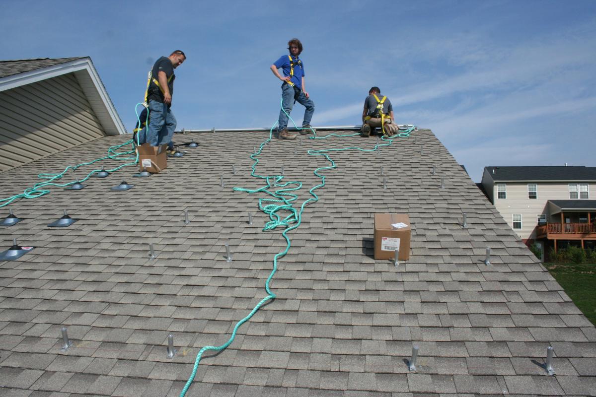
Figure 2. Roofing material and slope. (Source: IBACOS.) Identify the type of PV module being installed - panels or integrated tiles (e.g., PV shingles) Some PV shingles do not require any additional mounting hardware, making the following steps irrelevant. Follow the manufacturer’s installation instructions.
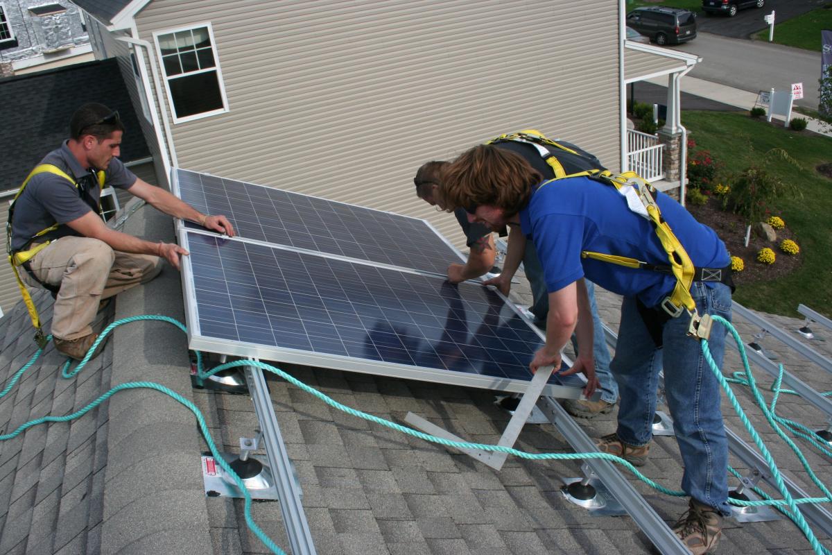
Figure 3. PV module installation. (Source: IBACOS.) Choose the most appropriate anchoring system for the project. Once the roof type (material and slope) and the type of PV module have been identified, choose the mounting system. When choosing a system, make sure that it includes the necessary components (as discussed above). Also, consider the efficiency of the installation process and the potential additional loads on the system from wind and snow. Reference the manufacturer’s documentation for the exact product to ensure that the anchoring system will integrate properly with the chosen PV module. Mounting bracket configurations are shown in Figures 6, 7, and 8.
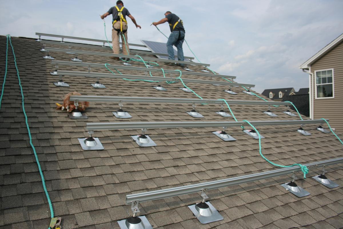
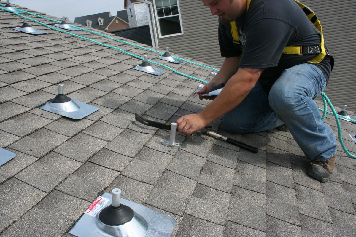
Figure 4. Anchor system installation. (Source: IBACOS.) Verify that installation of the PV modules and anchoring system was completed correctly, according to best practices. When the first row of PV modules has been installed on the anchoring system, check the installation to verify that it was completed to a high standard of quality. Implement quality control and quality assurance procedures to ensure that the design intent is met. This may help to prevent future costs related to weather damage or rework.
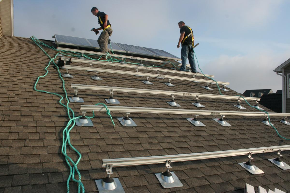
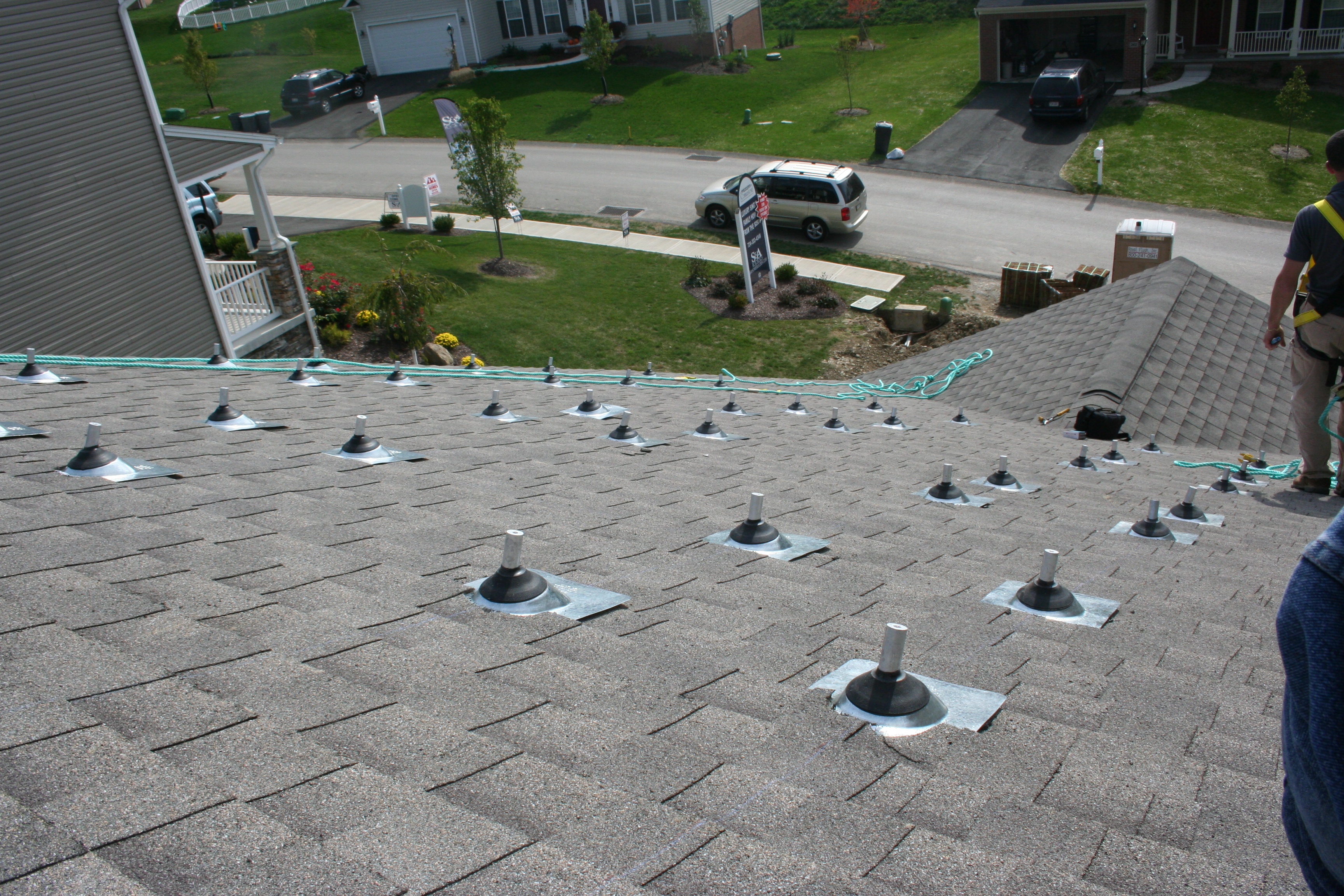
Figure 5. PV panel anchors are installed and flashed before installing racks and panels. (Source: IBACOS.)
Ensuring Success
Early in the design process, ensure that the correct type of mounting system will be used to integrate the PV modules on the roof and verify that the chosen mounting and racking system will be compatible with the PV panels. This can be done by considering the roof material, roof slope, weatherproofing, ease of installation, and wind and snow loadings. Closely examine the manufacturer’s product documentation for all of the systems involved, both early in the design process and throughout the installation.
Early in the project, confirm with local code officials that the mounting and racking system will meet all code requirements. Most jurisdictions require that PV installations are properly flashed and waterproofed according to roofing codes.
Inform the home owners that proper maintenance of the system is also necessary. The home owners should have a contractor annually check the tightness of the PV array’s bolted connectors with a torque wrench. All the panel clamps should be checked and spot checks should be made for bolts that connect rails to clip angles or posts (FEMA Rooftop Solar Panel Attachment 2018).
Region
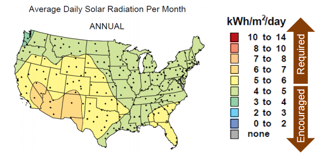
The DOE Zero Energy Ready Home PV-Ready Checklist (Revision 07) is required only under the following condition related to climate (See the Compliance Tab for other exceptions):
- The home's location, based on zip code, has at least 5 kWh/m2/day of average daily solar radiation based on annual solar insolation using the PVWatts online tool. See map below.
When choosing a racking and mounting system, factors such as the roof material, roof slope, weatherproofing, installation convenience, and wind and snow loads must be considered, particularly in hurricane-prone regions or other high-wind areas. Refer to Chapter 3 of International Residential Code (IRC 2018) for design wind load and other loading conditions. Some local jurisdictions may have additional requirements or require specific product approval. See the Compliance tab for more details. PV array installers and designers can use ASCE/SEI 7-16 Minimum Design Loads for Buildings and Other Structures for determining dead, live, soil, flood, tsunami, snow, rain, atmospheric ice, earthquake, and wind loads, and their combinations for general structural design.
Designing mounting systems for wind uplift is more critical in areas subject to hurricanes and excessive wind speeds. Manufacturers of collectors, modules, and mounting systems typically have their mounting systems pre-engineered for worst-case wind loads (DEG 2005). In parts of the world that are vulnerable to hurricanes or extreme wind storms, the collector and its mounting structure need to be able to withstand intermittent wind loads from 115 to180 miles per hour depending on the wind zone in which the home is being built. This corresponds to a pressure of about 75 pounds per square foot (FSEC 2006). Rudin and Becerra (2006) describe approaches for analyzing severe wind loads.
Wind loads may be greater near the roof ridge. Mounting collectors or arrays near the ridge may increase wind loads on the equipment (FSEC 2006). Similarly, locating collectors and arrays in from eaves may reduce wind loads (Rudin and Becerra 2006).
Design Guidance
Here is design guidance for anchoring PV systems in hurricane-prone regions: (from FEMA Rooftop Solar Panel Attachment: Design, Installation, and Maintenance 2018).
As an initial step in the design process, it is recommended that designers calculate wind loads on PV arrays in accordance with ASCE 7- 16 or the local building code, whichever procedure results in the highest loads. It is recommended that the design criteria in SEAOC PV2- 17 also be considered. Note, the Risk Category for rooftop PV is required to be not less than that for the building on which the equipment is located, nor that for any other facility to which the equipment provides a necessary service (ASCE 7-16, C29.3.1).
Hurricane-Prone Regions
- Recommend mechanically anchored PV rails or racks be specified, rather than ballasted racks, or rails/racks that are attached to the roof surface with adhesive.
- Specify panels that have a VSH rating per FM 4478.
- Recommend using microinverters where appropriate. Although these generally cost more than central or string inverters; they have several advantages. Unlike string inverters, microinverters have a greater chance of allowing undamaged panels of a PV array to continue to produce electrical power even if one panel is blown away or damaged by wind-borne debris. In an array using string inverters, if one panel is damaged, all the panels on the string will be offline.
- Recommend configuring PV power systems such that they can provide power to the building even if the municipal power is not operational.
For all regions:
- Specify PV panels that have sufficient uplift resistance to meet the calculated wind loads. Also specify the panel attachment to rails/racks, specify the attachment of rails/racks to clips or posts, and design the attachment of the clip or post to the roof support structure and/or the roof deck. If attachment is to the roof deck, verify that the deck has adequate attachment to resist the additional uplift load imparted by the clips or posts.
- Specify PV panels and rail/rack systems that have UL 1703 and UL 2703 listing (as applicable), and an ICC AC 428 evaluation report. If the building is insured by FM Global, specify that the PV system have an FM 4478 approval.
- Specify double-nutting the panel clamp bolts. For the first nut, specify nuts that are furnished with T-bolts. For the second nut, specify a stainless-steel lock nut with a nylon insert.
- Specify that all bolted connections be made with a calibrated torque wrench and torqued as specified by the PV system manufacturer.
- Specify that PV panels are not installed over roof drains and that walkways be provided to each drain so that drains can be easily checked for debris, cleaned and maintained as appropriate.
- Specify a walkway between rows of PV panels so that bolted connections can be checked annually.
Wind-Borne Debris
Neither ASCE 7, IBC, IRC, ICC AC 428, nor FM 4478 has wind-borne debris requirements for solar panels. In hurricane-prone regions, it is recommended that designers specify solar panels that have a damage rating of “VSH” (very severe hail) per FM 4478.
For seismic considerations, see the Structural Engineers Association of California (SEAOC) report, Structural Seismic Requirements and Commentary for Rooftop Solar Photovoltaic Arrays (SEAOC PV1-2012).
Training
Right and Wrong Images
Source
Source
Presentations

Videos

Compliance
ENERGY STAR New Homes and Apartments
International Residential Code (IRC)
Standards
Several associations are involved in standards development and best practices for roofing, including roofing systems for PV modules:
- The National Roofing Contractors Association (NRCA) produces manuals that discuss best practice guidelines for all aspects of roofing systems, including PV module installation.
- The Center for Environmental Innovation in Roofing (CEIR) attempts to improve communication between the roofing and PV industries. To do this, it created the Center PV Taskforce, which has developed best practices and guidelines for PV roof installation.
- The Tile Roofing Institute (TRI) is well known for its best practice guidelines for tile roofing systems and is a major player in the development of legislation and codes.
- The Sheet Metal and Air-Conditioning Contractors National Association (SMACNA) focuses on flashing details and building envelope metals. It produces manuals about flashing, with the focus on preventing building moisture intrusion.
ASCE/SEI 7- Minimum Design Loads for Buildings and Other Structures
Structural Engineers Association of California Wind Design for Solar Arrays (SEAOC PV2-17)
Retrofit
Installation and flashing of PV system anchors is similar for both new and existing homes.
More Info
References and Resources
*For non-dated media, such as websites, the date listed is the date accessed.
Contributors to this Guide
The following authors and organizations contributed to the content in this Guide.
Sales
Solar Electric Ready Home = Solar Electric Ready Home
Technical Description
As solar photovoltaic (PV) panels have significantly come down in price, many homeowners are installing them to produce clean power and reduce their electric bills. Many more homeowners are likely to want this option for the future. Solar electric-ready homes make this possible with minimal to no disruption or cost penalty using simple no-cost/low-cost details and best practices integrated during construction. This includes ensuring adequate unshaded roof space for the PV panels, installing conduit from the attic to the electric service panel, securing documentation that the roof is designed to support the extra weight of the PV array, and providing adequate space near the electrical panel for balance of system components.
Questions? Comments? Contact our webmaster.