

Scope
When reroofing a home or doing a renovation that creates a new penetration in the roof, inspect and replace or add flashing and sealing around all roof penetrations, such as vents, flue stacks, chimneys, sky lights, mounting brackets for solar panels, etc., to provide a continuous water control layer across the roof assembly, as follows:
- Inspect all of the penetrations through the roof to determine if proper flashing and other water management details are in place to prevent water leaks.
- Install flashing where missing around all new and existing roof penetrations through the roof.
- Install the water control materials in shingle fashion .
For more on roofs, see the U.S. Department of Energy’s Standard Work Specifications.
See the Compliance Tab for links to related codes and standards and voluntary federal energy-efficiency program requirements.
Description
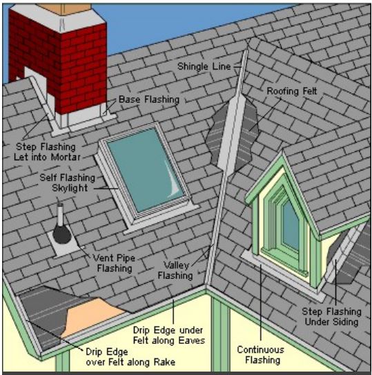
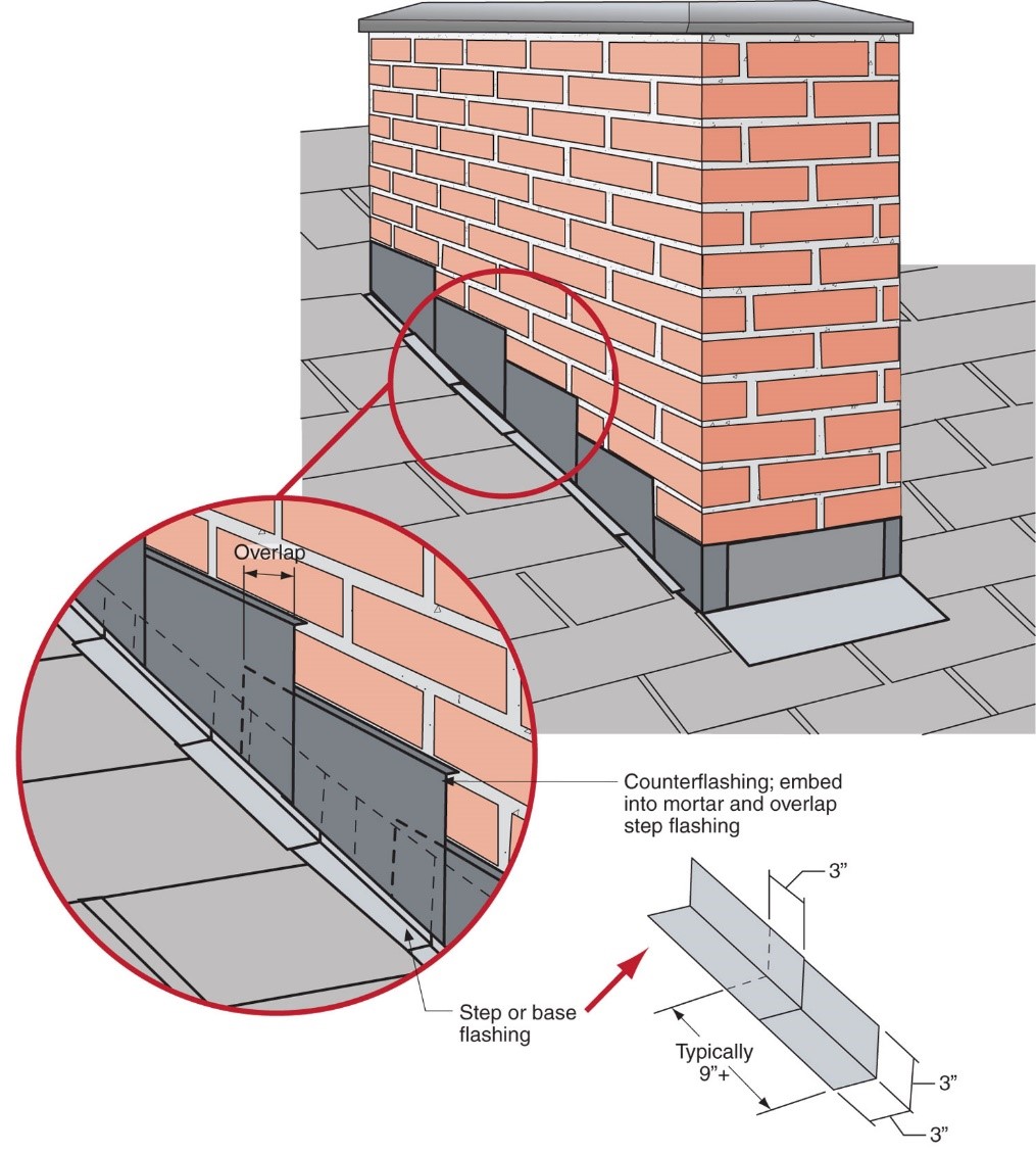
Vents, flue stacks, chimneys, sky lights, mounting brackets, etc., are all penetrations through a roof’s water control layer, which is the roof covering together with the roofing felt, synthetic underlayment, or other weather-resistant barrier installed over the roof decking. Any of these penetrations represent a weak spot in the roof’s armor where water could leak into the building, with the potential to cause significant damage over time. Whenever a new hole is cut in the roof, for example to install a flue, a skylight, an exhaust fan duct, or a brackets for solar panels, make sure that installation of proper flashing is part of the job. When the roofing on an older home is replaced, take the opportunity to inspect all of the flashing and repair or replace missing, damaged, or poorly installed flashing at all roof penetrations as well as at roof-wall joints and at valleys.
Controlling rainwater is the single most important factor in the design and construction of durable roof assemblies. The fundamental principle of water management is to shed water by layering materials such that water is directed down and out away from the building. The key to this fundamental principle is drainage.
Roofs should slope to drain water away from the top of buildings - the steeper the slope, the better. Any roof penetrations must be properly flashed to prevent water entry. The materials that form the water control layer should overlap each other in shingle fashion or be sealed so that water drains down and does not collect on the roof.
Membranes or formable flashings around roof penetrations should be integrated into the roof’s water control layer (or drainage plane) in a continuous manner and minimize the risks of water intrusion.
“Flat” roofs should never be truly flat—they should have some slope. A minimum slope of ¼:12 is recommended. Therefore, they could more accurately be called “low-slope roofs.” All low-slope roofs must be sloped to roof drains, scuppers, or edge details that carry rainwater off the roof.
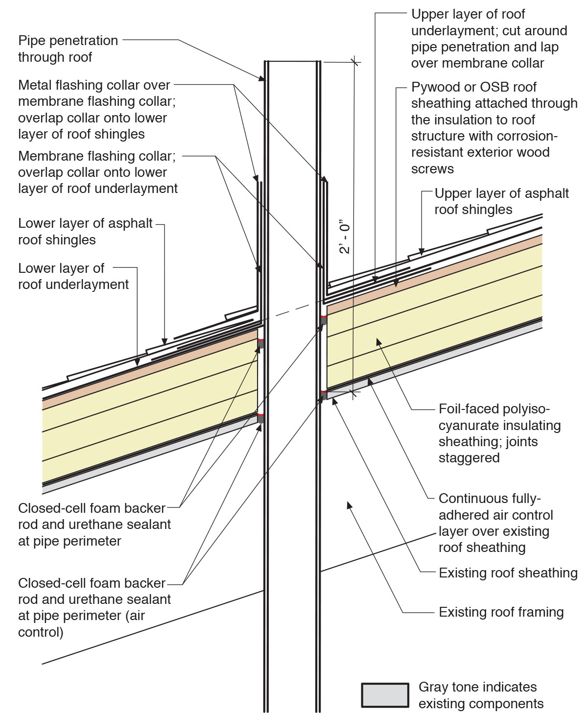
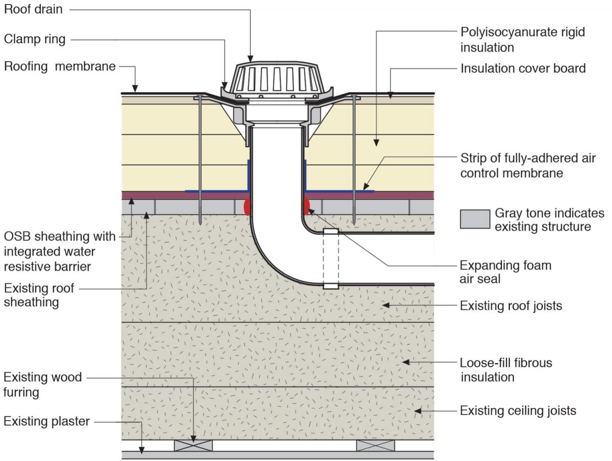
Figures 1 through 4 show examples of water management details around four common roof penetrations – a plumbing vent pipe through an insulated sloping roof, a roof drain, a skylight curb, and a solar panel mounting bracket through a low-slope roof. The figures show the water management details integrated with rigid foam insulation that has been installed above the roof deck and beneath the cladding as part of a roof insulation upgrade. However, in most aspects, these details also apply to roofs that do not have rigid foam installed on the roof deck.
Further details for sealing around a pipe in a sloping asphalt shingle roof are described in the how-to steps.


How to flash around a vent pipe roof through a sloping roof with rigid foam installed above the decking.
This sequence of steps shows a plumbing vent pipe penetration through a sloping roof with insulation retrofitted on top of the roof deck. The attic in this detail is conditioned interior space.
- Inspect the integrity of the roof system (roofing membrane and/or cladding). Check for any deficiencies, water damage, active leaks, etc. Proceed with re-flashing only if required repairs have been performed.
- Inspect the structural integrity of the roof. Check the roof framing for any deficiencies, rot, insect damage, etc. Proceed with re-flashing only if required repairs have been performed. Based on the findings, review specific detailing, and revise the roof assembly plans as needed. Follow the minimum requirements of the current adopted building code regarding the wood roof framing construction.
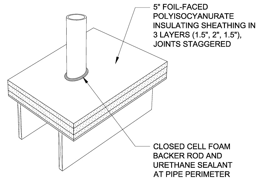
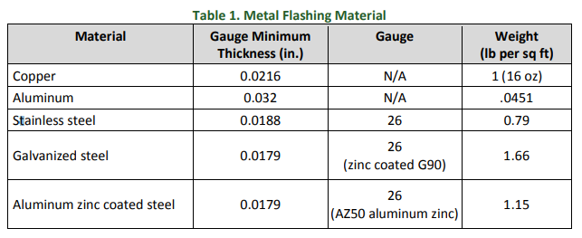
Cut a hole through the roofing that is 0.5 inches larger than the pipe and install the pipe. Extend the pipe 2 feet above the roof sheathing. Install closed-cell foam backer rod and urethane sealant in the hole around the pipe as an air control layer.

- Install insulating sheathing in multiple layers with joints staggered and taped. Install closed-cell foam backer rod and urethane sealant at the pipe perimeter.
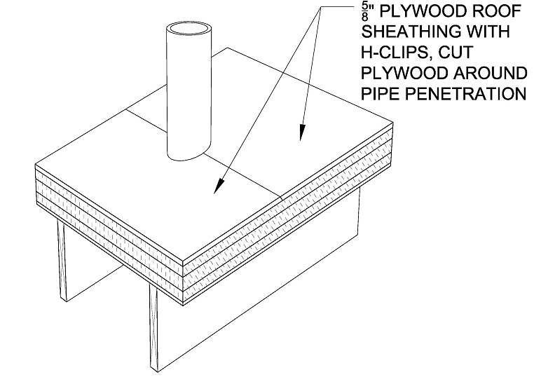
- Install 5/8 in. plywood roof sheathing over the layers of rigid foam using H-clips and screw fasteners that extend through the foam to the structure. Cut the plywood to fit snuggly around the pipe.
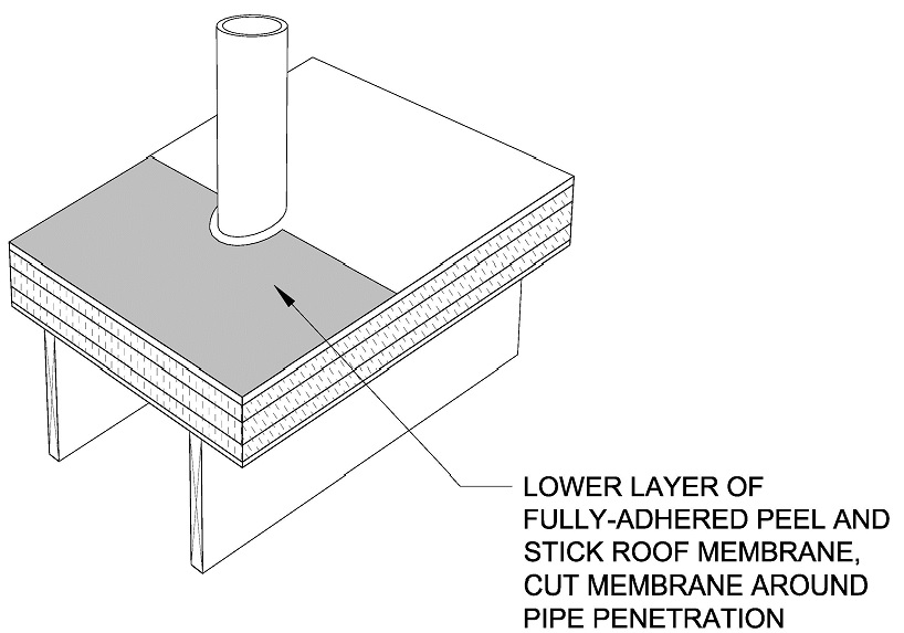
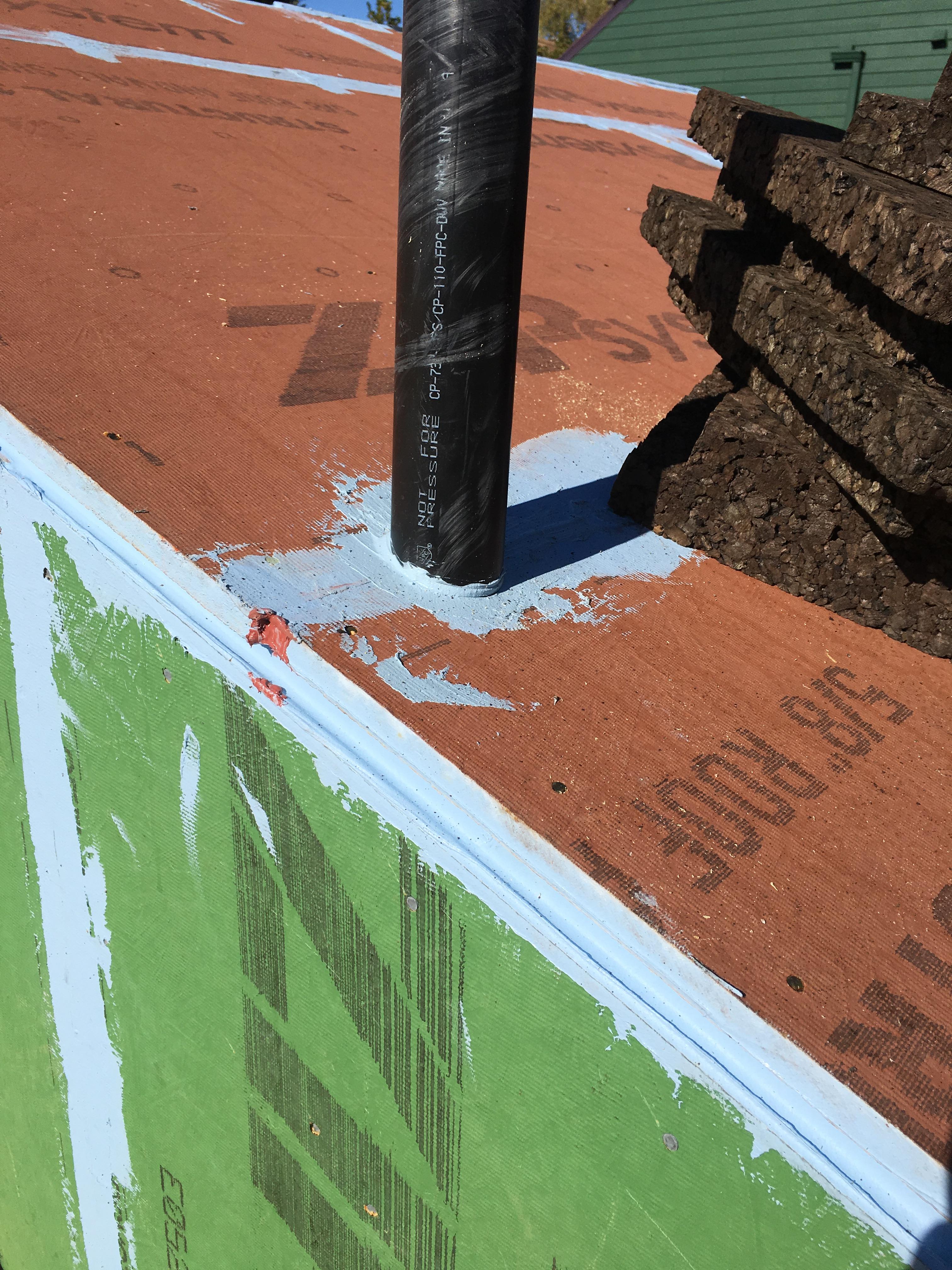
- Cut two sections of peel-and-stick roof membrane that will each extend out from the vent pipe for 18 inches. Cut a half-circle notch out of each section so the membrane will lay flat around the pipe. Install the section of membrane on the downhill side of the pipe first, to fit around the pipe penetration and lay flat.
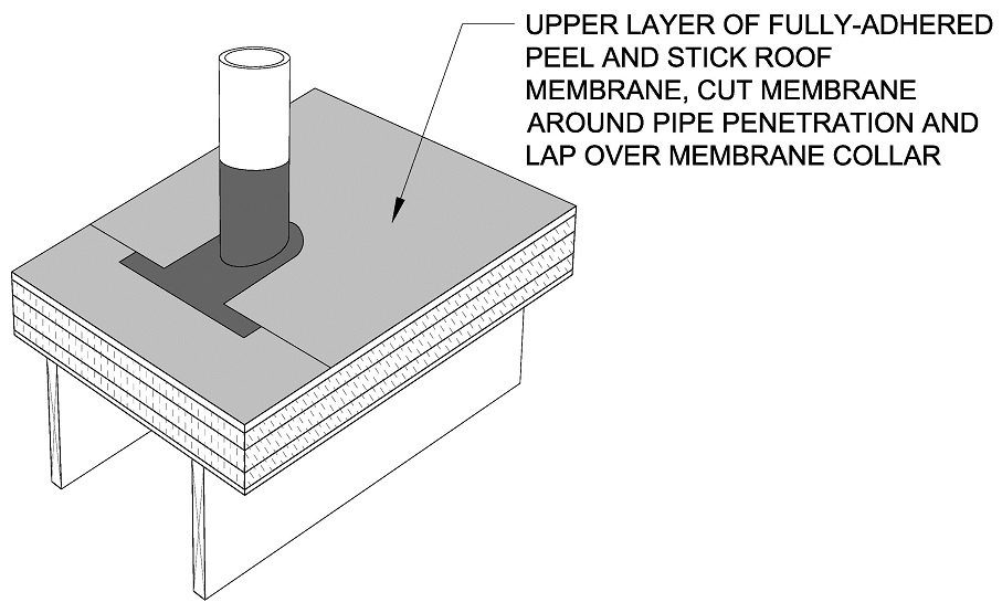
- Install a piece of formable self-adhered flashing membrane around the pipe like a collar, This collar will overlap the down-slope piece of fully adhered roof membrane.

- Install the upper layer of the fully adhered roof membrane. Cut the membrane around the pipe penetration and lap it over the pipe collar and over the edge of the lower layer of membrane. A flexible-type membrane is ideal for flashing around pipes.
- Install asphalt shingles, stopping just below the pipe.
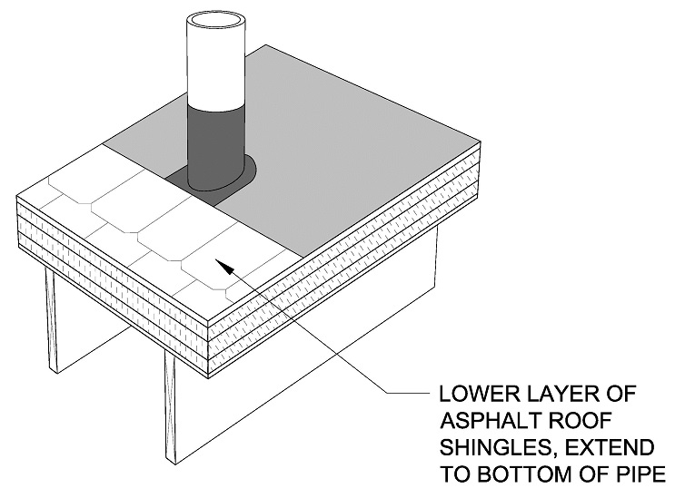
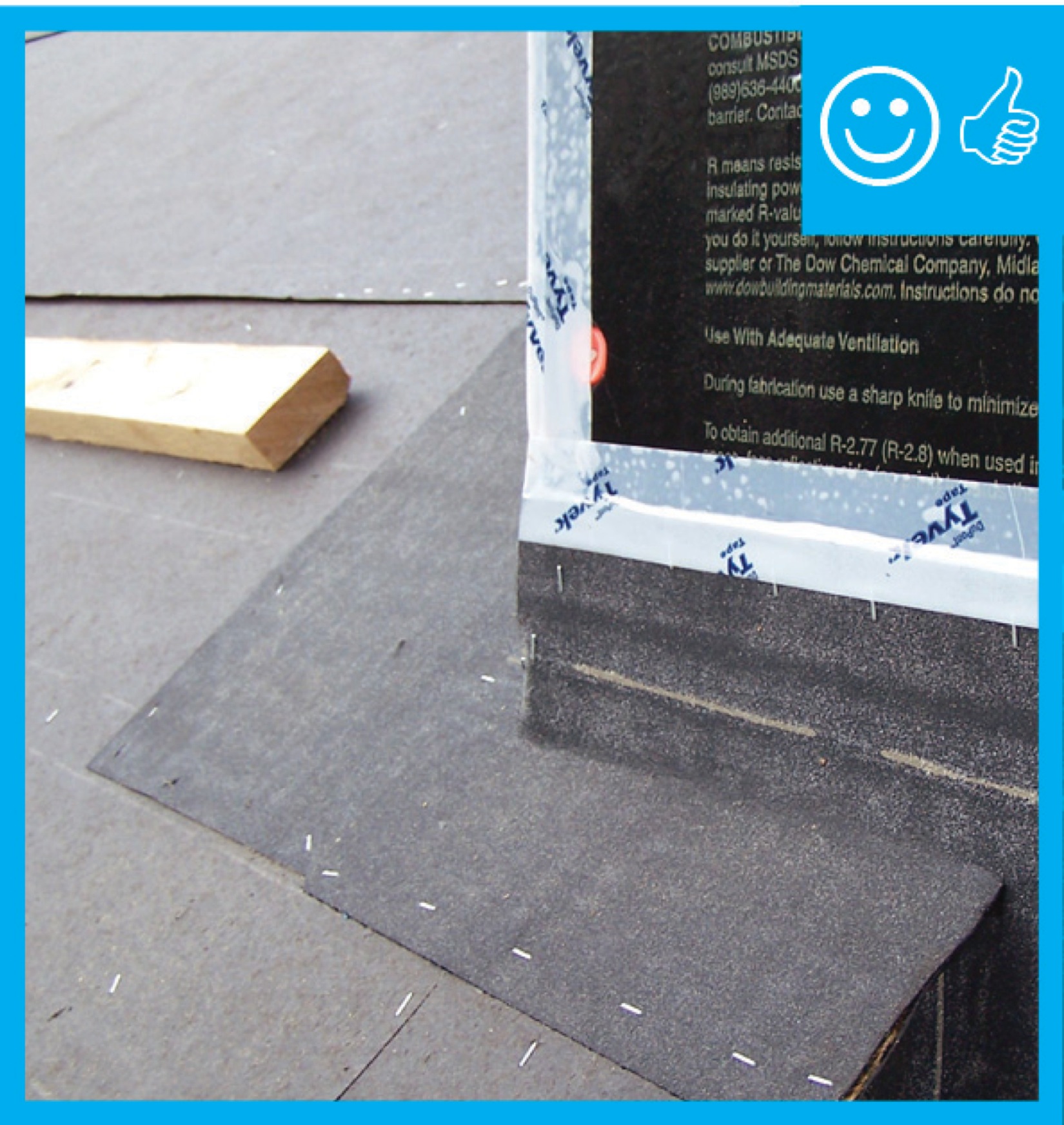
- Install the metal/rubber flashing collar over the membrane flashing collar. Overlap the metal collar onto the lower layer of the asphalt shingles.

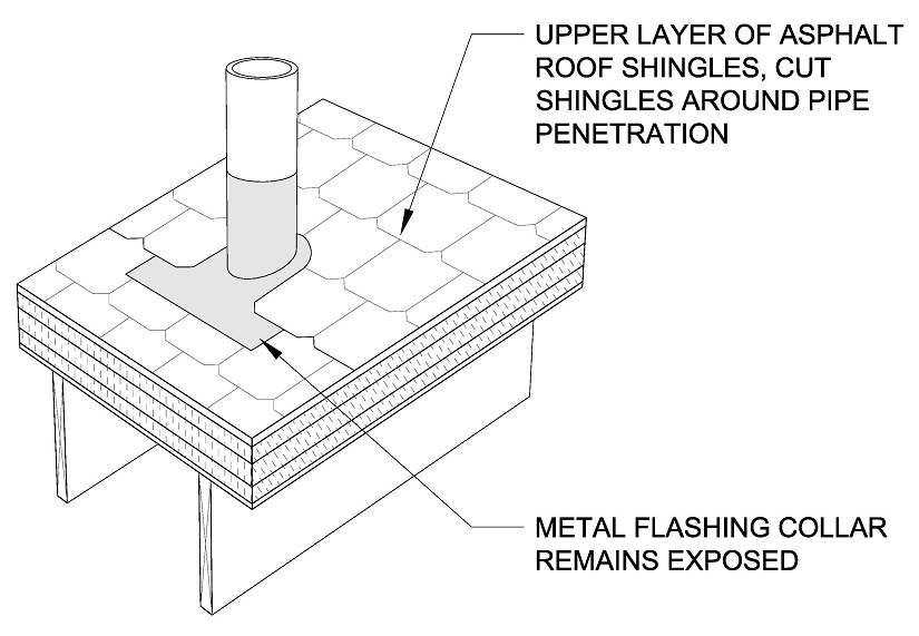
- Continue installing shingles around and above the pipe. These shingles will cover the upper edge of the metal flashing collar. Cut the shingles around the pipe penetration.
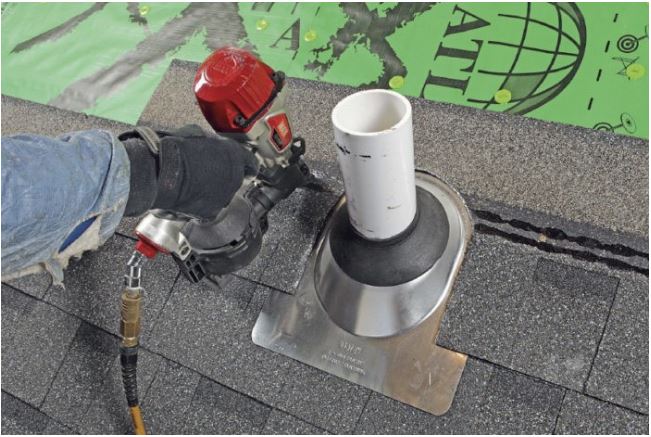
Regarding the metal pipe flashing, the Insurance Institute of Building and Home Safety (IBHS) Fortified Home program recommends the following in its General Flashing Guidelines for Steep-Sloped Roofs:
- Use corrosion-resistant metal flashing with a thickness of not less than designated in local building code or the metal flashing material table, Table 1 (excerpted from the IBHS Fortified General Flashing Guidelines for Steep-Sloped Roofs).
- Unless otherwise noted to be more restrictive, fasten all metal flashing at a maximum of 6 in. on center at the edges with approved compatible corrosion-resistant fasteners.
- Prime metal surfaces receiving approved flashing cement with ASTM D41 primer.
Use approved flashing cement in compliance with the roof system manufacturer’s installation instructions.
Ensuring Success
Inspect the existing roof framing for any deficiencies and make any corrections if necessary.
Ensure that the water control layers of the roof system overlap each other in shingle fashion.
Region
Hurricane-Prone Regions
The IRC does not have additional requirements for sealing and flashing roof penetrations in hurricane-prone regions or other high-wind areas. Some local jurisdictions may have additional requirements or require specific product approval. Building codes establish minimum requirements, but products must also be installed in accordance with manufacturer’s instructions. This is important because codes typically do not provide all the detailed information for a durable installation. Assessments by FEMA after hurricanes commonly find that water intrusion and structural building failures are due to improper installation of building components. So, even where the IRC does not require additional measures, proper installation is more critical in hurricane-prone regions. See flashing details in the Insurance Institute of Building and Home Safety (IBHS) Fortified Home program General Flashing Guidelines for Steep-Sloped Roofs.
Training
Right and Wrong Images
Source
Source
Guide describing details that serve as a visual reference for each of the line items in the Water Management System Builder Checklist.
Source
Fact sheet describing flashing of roof penetrations to make a home more resistant to high winds, hurricanes, and rainwater intrusion.
Source
Fact sheet describing flashing of roof penetrations to make a home more resistant to high winds, hurricanes, and rainwater intrusion.
Source
Source
Source
Videos


CAD Files

More Info
References and Resources
*For non-dated media, such as websites, the date listed is the date accessed.
Contributors to this Guide
The following authors and organizations contributed to the content in this Guide.
Questions? Comments? Contact our webmaster.