

Scope
To retrofit the roof of an existing home for high-wind or seismic resistance:
- Install a two-part spray-applied polyurethane foam adhesive to the underside of the roof to increase the uplift strength and rigidity between the roof sheathing and the trusses or rafters.
- Install structural screws or metal straps to connect the roof and wall top plate framing to increase the strength of the roof trusses or rafters against uplift.
- Install skylights and windows with impact-resistant glass in regions that experience high winds and hurricanes. Or, provide coverings for non-impact-resistant skylights and windows.
See the following Building America Solution Center guides for more information:
- Pre-Retrofit Assessment of Attics, Ceilings, and Roofs
- Pre-Retrofit Assessment of Hazardous Materials
See the U.S. Department of Energy’s Standard Work Specifications (SWS) for more on installing spray polyurethane foam in unvented attics.
See the Compliance tab for links to related codes and standards and voluntary federal energy-efficiency program requirements.
Description
Today’s building codes already incorporate stringent requirements to help protect new homes from catastrophic failures during high winds, hurricanes, or seismic events. However, older homes built to the weaker building codes of the past are at risk.
These older homes are likely to lack the metal connectors that make a home far more resistant to uplift forces during high winds or the necessary braced wall paneling to resist shear forces during an earthquake. Older, unreinforced homes can incur extensive damage when subjected to high winds or a seismic event, threatening the safety and security of the occupants. Fortunately, an arsenal of retrofit solutions exists for strengthening existing homes. Additionally, insurance companies sometimes provide significant financial incentives to homeowners to perform such retrofit strengthening work.
Retrofit bracing and strengthening a roof consists of strengthening the connections of the roof decking to the rafters or trusses, , the rafters/trusses to the top plate, and the wall studs to the top and bottom plates, and increasing the shear strength of the wall. The last point is covered in-depth in a separate Solution Center guide, Bracing of Roofs for Hurricane, High Wind, and Seismic Resistance.
Retrofit Strengthening of the Roof Decking to Rafter/Truss Connection without Roof Cover Replacement Using High-Density Spray Adhesive
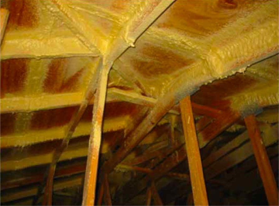
The roof decking to roof rafter/truss connection strength can be doubled without replacing the roof covering by applying a two-part, spray polyurethane foam adhesive to the underside of the roof deck as shown in Figure 1 (ASC 2008). At approximately $1.65 per square foot of roof deck, this method is an economical option for strengthening the roof sheathing to rafter/truss connection when the roof does not need to be replaced (Personal communications with Jimmy Burgess at FoamSeal, August 18, 2020). For cathedral ceilings, any interior wall finish such as drywall and cavity insulation will need to be removed to perform this task.

The spray adhesive used must meet the following minimum requirements:
- The product must be tested and evaluated in accordance with either ASTM E330, Standard Test Method for Structural Performance of Exterior Windows, Doors, Skylights and Curtain Walls by Uniform Static Air Pressure Difference (applied to roof sheathing), or TAS 202-94, Criteria for Testing Impact and Non-Impact-Resistant Building Envelope Components Using Uniform Static Air Pressure. The minimum allowable design uplift pressure must be greater than or equal to 110 psf and the proof test pressure achieved without failure or structural distress must be greater than or equal to 165 psf.
- The adhesive must be a two-component spray polyurethane foam system with a minimum core density of 1.5 to 3.0 pcf in accordance with ASTM D1622, Standard Test Method for Apparent Density of Rigid Cellular Plastics.
- Spray polyurethane foam adhesive systems must be installed by a properly trained and qualified applicator in accordance with the manufacturer’s maintenance and installation guidelines.
The spray adhesive is applied to the underside of the roof in the attic in a 1.5- to 3-inch-deep layer to all joints between sheathing, all intersections between roof sheathing and roof framing members, and all valleys. The adhesive has an added benefit of sealing the joints of the roof deck to help prevent water intrusion. While not as effective as installing an underlayment, the adhesive will help minimize water infiltration. Consult local building codes prior to using this adhesive method in high seismic risk locations because it may be too effective and cause the building to transfer loads to the foundation with a shorter period and higher amplitude, causing overloading of the foundation supports (Cushman 2009).
Retrofit Strengthening of the Roof Decking to Rafter or Truss Connection with Roof Cover Replacement using Additional Nails
The best way to strengthen the connection between the roof decking and the rafters or trusses is to add nails to the roof decking and to ensure the nails penetrate into the rafters or trusses below. This requires access to the roof decking from above and thus this method can only be accomplished with a roof cover replacement. The Fortified Roof program (sponsored by the Insurance Institute for Business and Home Safety [IBHS]) recommends 8d smooth-shank nails spaced nominally at 4 inches on center (in. o.c.) along all framing members or 8d ring-shank nails at 6 in. o.c. along all framing members. See Fortified Home’s Re-Roofing Checklist and other roofing resources for guidance on making the home more hurricane and high wind resistant.
Retrofit Strengthening Wall to Truss or Rafter Connection with Metal Connectors
Although the Fortified certification program considers upgrading or verifying the connector hardware forming the continuous load path in an existing home to be very difficult, it is possible to strengthen the connections in an existing home. It may be cost prohibitive to remove enough finishes to add all of the metal connectors that would be required to meet the structural requirements of a new home; however, strengthening a home should not be viewed as an all-or-nothing task. Because it is challenging to retrofit, it is helpful to know what locations are the most critical to strengthen and to know about innovative products that can make the task easier.
The areas that experience the highest wind uplift loads on a roof are the outside corners and the gable ends. Thus, the most important areas to retrofit are the 6 to 8 ft nearest the outside corners and the gable ends. This is not to say that there is no value to adding tie downs at every roof-to-wall connection. However, if time and finances are limited, these are the areas to prioritize. The prioritization is also driven by a requirement introduced in 2006 in Florida requiring single-family structures valued at $300,000 or more that are in the wind-borne debris region to receive an inspection of their roof-wall connections (FBC 2006). If they are found to be inadequate, there is a mandate to retrofit the roof-to-wall connections by installing new hardware or adding nails to existing hardware, starting with reinforcing the corners. (The Florida legislatures put a cap on the retrofits of no more than 15% of the total cost of re-roofing the home.)
The installation of metal roof-to-wall connectors can be accomplished in three ways in a retrofit application. Sometimes multiple methods are needed in one home due to the home’s layout.
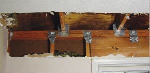
The metal connectors can be installed from the inside. A few square inches of drywall at the top of the wall and the ceiling will need to be cut and removed to expose the wall top plates, the truss or rafter, and a few inches adjacent to allow working room for the metal connector to be installed, as shown in Figure 2. A stud finder can sometimes locate the truss or rafter location while other times it might be easier to locate the rafter or stud by using a reference point locator tool with the transmitter placed on the truss or rafter from the attic. If the attic insulation is a blown-in variety such as fiberglass or cellulose, a rake can be used in the attic to move the insulation out of the way so it doesn’t fall into the room when the drywall is cut. The drywall is patched after the connectors have been installed.
The metal connectors can be installed from the outside by accessing the roof-to-wall connection through the soffits. Depending on the soffit material, some nails may need to be pulled and care must be taken as vinyl soffit panels may crack when being removed. As a result, installing the metal connectors this way may result in some soffit material needing replacement. If the soffit material can be reused, label each piece so they can be replaced in the same way. In hurricane zones, it is recommended that vinyl soffit vent covers that rest in J channels be replaced with mechanically fastened metal soffit vent covers that provide greater resistance to displacement in heavy winds.
Metal connectors can also be installed during reroofing. The roof sheathing at the eaves is removed to expose the roof-to-wall connection, allowing straps, clips, or right-angle brackets to be installed. This is the most economical option if a new roof is already needed. For more details about retrofit procedures, please see the Wood Frame Roof-to-Wall Connections page in the Hurricane Retrofit Guide (2010) by the Florida Division of Emergency Management.
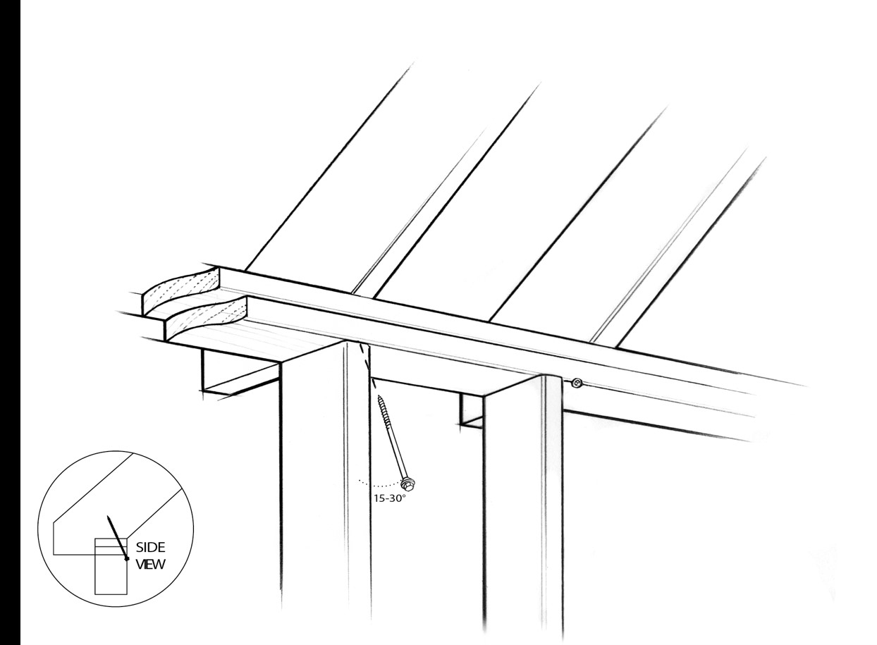
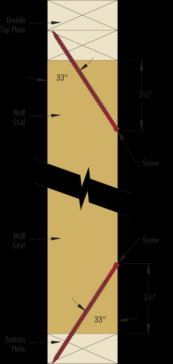
New products can help make the task of increasing the uplift strength of the roof to wall connection easier. The connection of studs to their top and bottom plates can be strengthened with engineered structural screws specifically designed for this purpose. These engineered structural screws can offer resistance to uplift and lateral loads comparable to a hurricane tie while being easier to install in retrofit applications, as shown in Figure 3. If interior wall finishes such as drywall are present, a minimum amount will need to be removed to expose the wood connections for installation of the screws. By comparison, a metal connector would require that enough drywall be removed to allow room for nails to be installed from the side. Structural screws are usually 6 inches long and they are driven using an angle guide from the bottom corner of the double top plate through the top plates and into the rafter or truss. Please check with your local building code officials to see if these designed structural screws are acceptable alternatives to metal connectors.
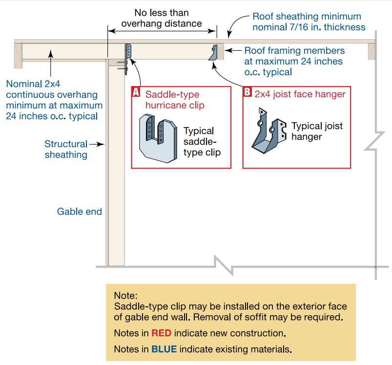
Retrofit Strengthening of the Gable Overhang-to-Gable End Wall
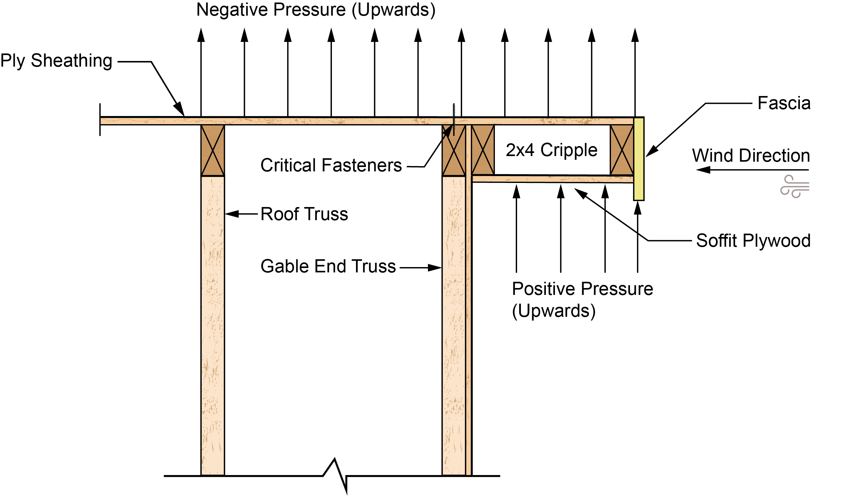
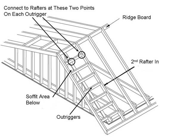
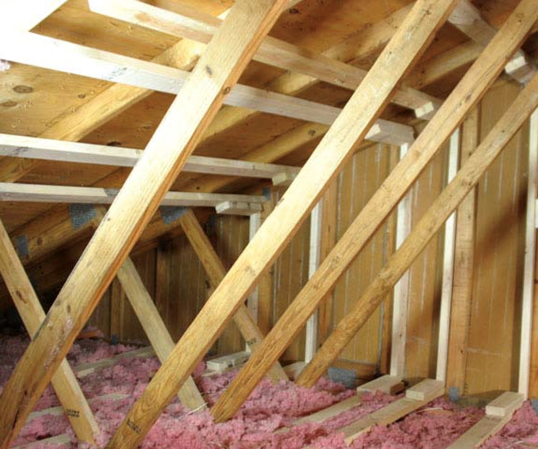
The most frequent building failure in hurricanes is due to a weak gable overhang-to-gable end wall connection. The failure due to uplift wind forces causes the roof sheathing and gable end wall to also fail. The gable overhangs in older homes are sometimes built using what is known as the attached ladder detail. This gable construction method, shown in Figure 4, consists of framing dimensional lumber into a ladder shape and then nailing it to the gable end wall. This is a much weaker method for constructing an overhang compared to the lookout or outrigger framing method shown in Figure 5, especially for deep overhangs. (Both figures are based on figures from the Gable End Overhangs section of the Hurricane Retrofit Guide by the Florida Division of Emergency Management, 2010.) The lookout/outrigger framing method provides two points that can be strengthened with metal connectors, one where the lookout/outrigger connects with the second rafter/truss and the other where the lookout/outrigger connects with the top of the gable end wall, as shown in Figure 5. The ladder framing method provides no such place to add strength.
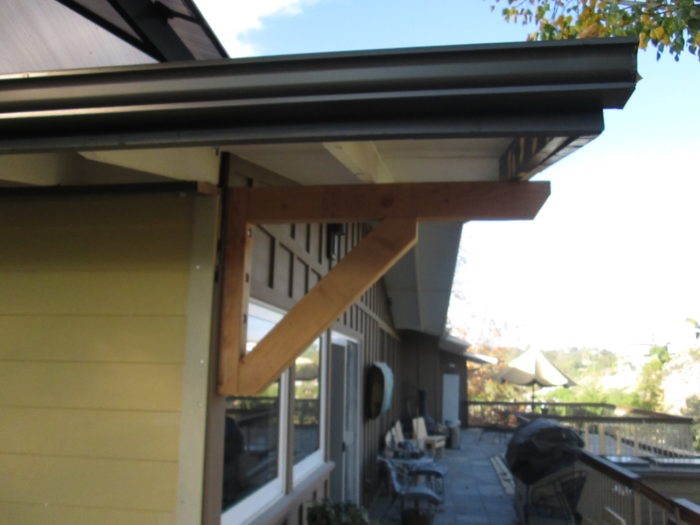
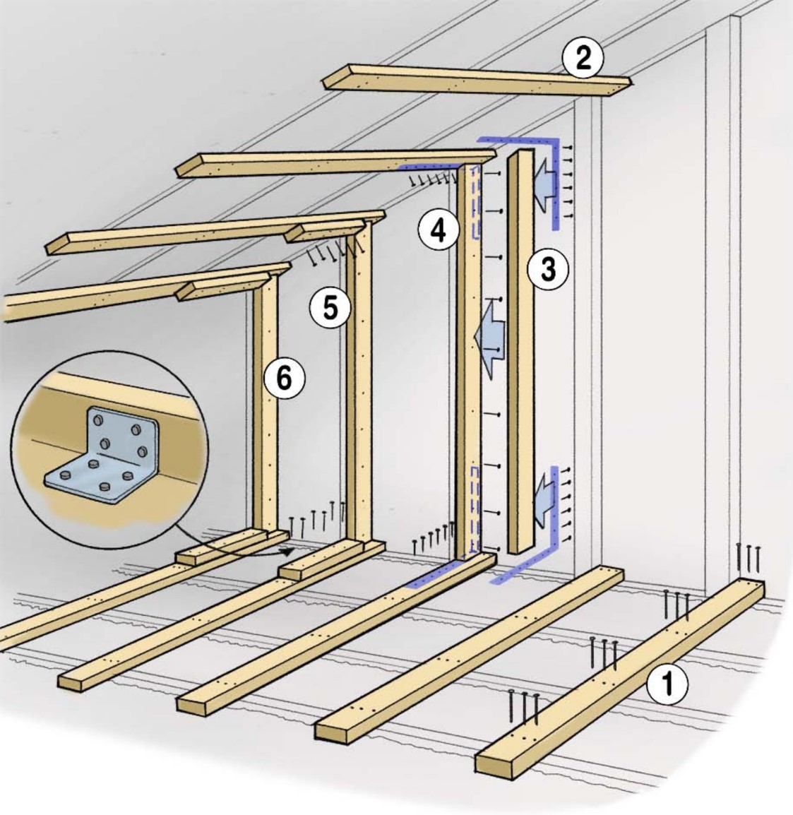
There are a few ways you can strengthen a gable overhang that was originally framed using the ladder method such as by adding angle support framing underneath, as shown in Figure 6. This greatly strengthens the overhang-to-gable end wall connection. The second step is to strengthen the gable end against wind pressures that push and pull the wall out by bracing it to the second, third, and fourth rafter truss using metal connectors and dimensional lumber. There are two commonly accepted methods to do this, called the L-Bent Straps and the U-Bent Straps methods. Please refer to this Gable End Retrofit Guide by the Florida Division of Emergency Management (2011) for detailed instructions. Note the exterior angle overhang support framing needs to be constructed using lag bolts screw, not nails, because this support needs to resist large uplift forces.
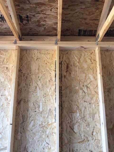
Retrofit Strengthening Stud to Top and Bottom Plate Connections in Gable End Walls
Gable end walls are the triangular walls that enclose the home beneath the peak end of a gable roof; they rest on top of a rectangular wall. Gable end walls often enclose a vented attic; however, they can also enclose an unvented attic or the home could have a cathedral ceiling. In the latter case, the rectangular part of the wall seamlessly transitions to the triangular section. The gable end walls that enclose a finished attic or a cathedral ceiling are often built stronger than a gable wall that encloses a vented attic.
Regardless of what the gable end wall encloses, the gable end wall should be carefully examined because that wall is often the tallest and largest vertical surface in a home. Homes that were built before 2002 and certainly homes built before 1997 should be examined to look for significant strength deficiencies. Due in part to poor construction and in part to their size, gable end wall failures are the most frequent wall failures in hurricanes. In a hurricane, some roof-to-wall connectors could experience an uplift force of up to 1,200 pounds. The stud-to-top and bottom plate connections need to be able to transfer this force to the ground without pulling apart. This is why it is important to ensure that all of the load paths that connect to the roof are adequately strong.
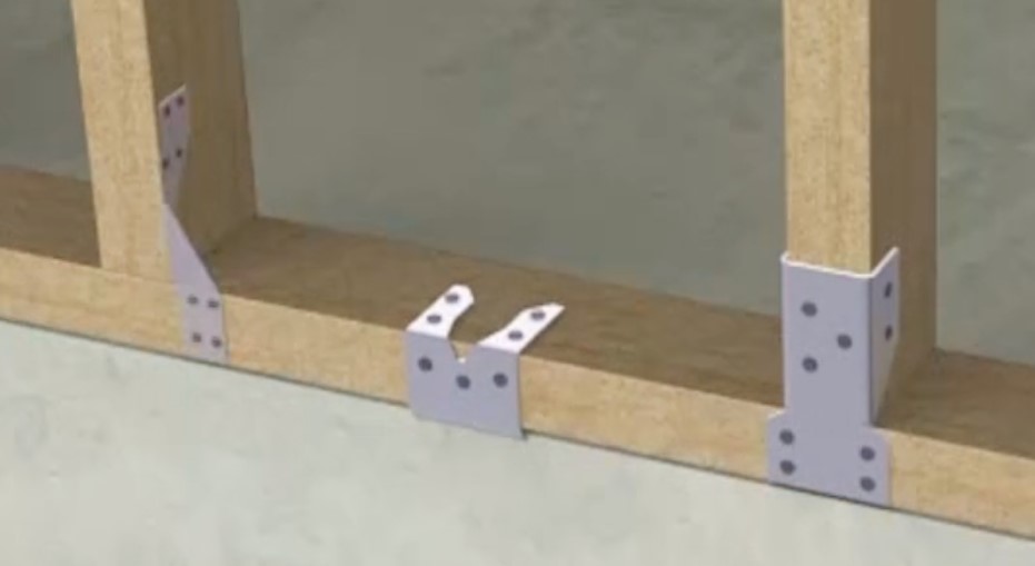
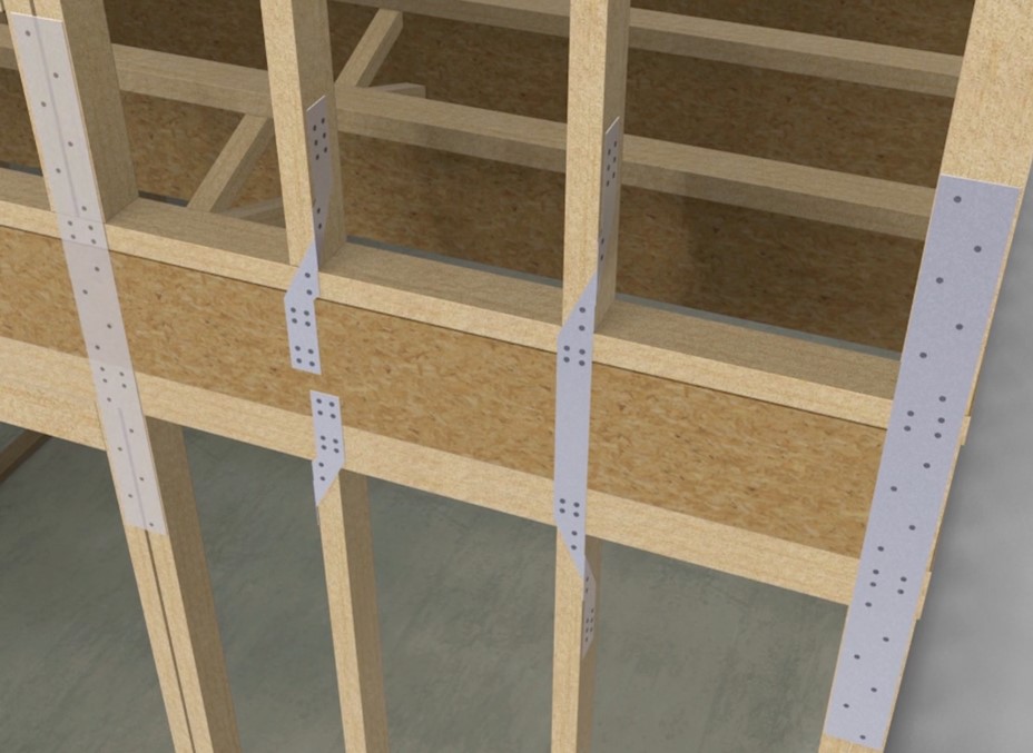
Similar to retrofit strengthening of the roof-to-wall connection, strengthening the stud-to-top and bottom plate connections can be challenging and messy to do. Unlike the roof-to-wall connection, there are not multiple ways to access this connection. The metal connectors used to provide uplift strength at these connections in new construction are shown in Figures 7 and 8. As you can see from the locations of these metal connectors, they are not accessible without removing the siding and weather-resistive barrier of the home. Fortunately, metal connectors provide the same strength regardless of whether you place them on the inside or outside face of a wall as long as you are consistent. Adding these connectors by removing some drywall wall that can subsequently be patched is often a much simpler approach than removing the siding.
Similar to the roof-to-wall connection, it may be time and cost prohibitive to retrofit an existing home with enough metal connectors to make the stud-to-top and bottom plate connections meet the structural requirements of a new home; however, strengthening a home should not be viewed as an all or nothing task. Thus, one has the opportunity to prioritize which walls to strengthen first. Due to their large size, gable end walls experience the greatest wind pressures and simultaneously need to manage the uplift forces transferred to them from the roof. For homes with gable end walls, these walls should take priority when retrofitting for wind uplift resistance.
Like the roof-to-wall connection, while the standard method is to use metal connectors, in a retrofit situation, time and cost constrains may dictate the use of alternative hardware and approaches that would result in getting more than halfway to the uplift strength of a new home. If the interior method was selected to perform the roof-to-wall connection strengthening, the stud-to-top plate connection should be done in concert as shown in Figure 2.
As an alternative to metal connectors, the connection of studs to their top and bottom plates can be strengthened with engineered structural screws specifically designed for this purpose. These engineered structural screws can offer resistance to uplift and lateral loads close to the strength of a metal connector while being easier to install in retrofit applications, as shown in Figure 9. If interior wall finishes such as drywall are present, a minimum amount will need to be removed to expose and access the wood connections for installation of the screws.
The connection between the second floor and first floor can be strengthened by connecting the bottom plate and the first-floor top plate using a threaded rod and metal hold downs, as shown in Figure 10. A bit more drywall will need to be removed to gain enough working room to drill and install the threaded rod and metal hold downs. Strengthening the connection between the first and second floor is beneficial for homes in both high wind regions and seismic regions. Please consult an engineer to help determine the best hold downs to use and the best location to place the hold downs.

Retrofitting Skylights and Windows to be Impact-Rated
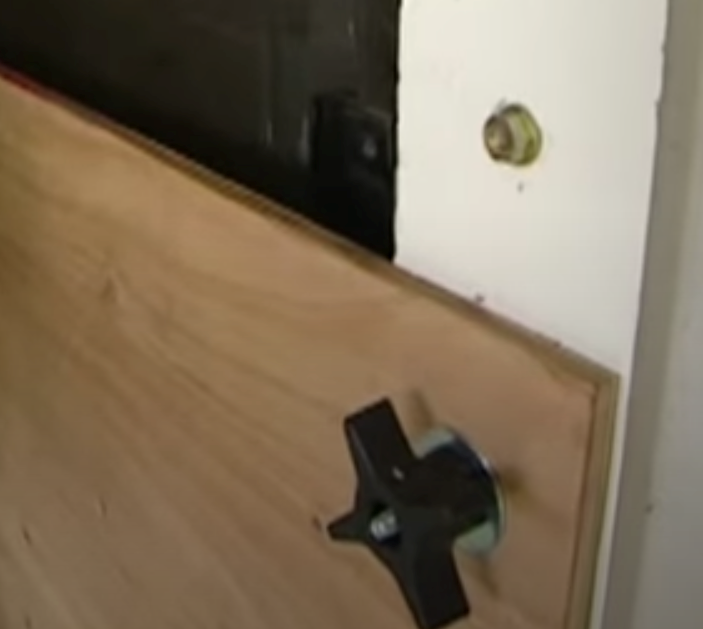
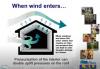
Hurricane force winds can easily lift large heavy objects and turn them into high-velocity projectiles that can strike windows and skylights. A breach in the building envelope can not only cause severe water damage, it can significantly increase the wind loads on a structure. A breach in the building envelope on the windward side of the building will result in a significant positive internal pressure increase, which contributes to the uplift force on the roof. Homes are normally not designed to withstand these pressurization loads from within; they can cause a roof to blow off. This progressive failure can be prevented by protecting the glazing in the building envelope from being breached. While replacing windows with ones that have impact-rated glazing is an option, it is a rather expensive option. A more economical option may be to purchase or construct window coverings. One way to make the windows easy to board up is to precut and label plywood pieces sized for each window and to install threaded rod fittings into the window frame. When the windows need to be boarded up, threaded rods can be fitted into the fittings and the plywood boards secured using female threaded knobs as shown in Figure 11 and the video Hurricane Retrofit a Home (Holigan 2014).
Ensuring Success
Retrofitting a home to increase structural strength and resistance to the forces of hurricanes, high winds, and earthquakes requires creative solutions and building science knowledge. Most structural upgrades require that a structural permit be obtained from the local building codes jurisdiction. Getting the structural upgrades approved prior to the work being performed and then inspected allows a third-party to help ensure success.
If a two-part spray-applied polyurethane foam adhesive is applied to the underside of the roof sheathing to strengthen its connection to the roof rafters or trusses, request the installer or manufacturer to provide evidence that the product has been approved for use to adhere roof decking to roof rafters. Alternatively check the product to see if it has been approved by the Florida Department of Business and Professional Regulations, which maintains a searchable database of approved products for a specific application. As of this writing, there are at least six products approved for this application.
If the roof decking to roof rafter or truss connection is strengthened during re-roofing, write the address and date on the decking and take pictures of the decking to have a record of the nail pattern. These pictures can be used for permit inspection approvals, to help get a Roof certification, and to add value to the home when it is sold. Even in jurisdictions where it is not required, re-roofing is an excellent opportunity to remove the sheathing along the roof eaves to inspect the hold-down connections between the roof rafter and truss walls. If found to be insufficient, this is the most economical time to add metal connectors.
If your home was built before 1997, it is recommended that the gable overhangs be inspected to see how they were framed. If they were framed using the ladder method and the house is in a location that experiences high winds, it is strongly recommended that the overhangs be strengthened. Consult your local building codes jurisdiction to see if a permit is required for this work. If a contractor is hired to perform the work, refer the contractor to the Gable End Retrofit Guide by the Florida Division of Emergency Management (2011) for detailed instructions on the L-Bent Straps and the U-Bent Straps method of strengthening the gable overhang. If an exterior angle overhang support is added be sure to use structural lag bolts or screws, not nails, for the task.
If the stud to top and bottom plate connections are strengthened, consult an engineer to help you determine (1) where this upgrade would produce the most performance for cost in the home, and (2) which metal connectors or structural screws to use. Obtain the necessary permits to do the work. Document the work with photos and keep notes on where in the home the work was performed. This documentation will be valuable if one is seeking a Fortified Home certification and will certainly add value to the home when it is sold.
If windows and skylights are replaced, replace them with units that have impact-rated glass if the house is in a location where they are required. However, even if a building is outside the required zone, it may be a good idea to have impact-resistant glass windows if the home is located in a region that experiences high winds or hurricanes. If the windows and skylights are not in need of replacement, consider purchasing or constructing window covers that can be easily installed before the next hurricane.
Region
Climate significantly impacts the design requirements and the shear and uplift forces that the various connections in a home must resist. The first step is to know what the ultimate wind speed and seismic design category are for the location of the home. Your local building code jurisdiction will have zoomed-in versions of the national wind maps presented in IRC Figure R301.2(4)A and R301.2(4)B and the national seismic map in IRC Figure 301.2(2). Alternatively you can find the ultimate wind speed for your address by entering it in the online ASCE 7 Hazard Tool. Be sure to select the correct ASCE 7 version that matches the ASCE 7 version used in the IRC adopted by your local building codes jurisdiction. The seismic design category of your building address can also be found using the Seismic Design Map Tool by the Structural Engineers Association of California (note, this tool works nationally not just in California). The 2018 and newer IRC uses ASCE 7-16 whereas the 2015 version of the IRC uses ASCE 7-10.
Training
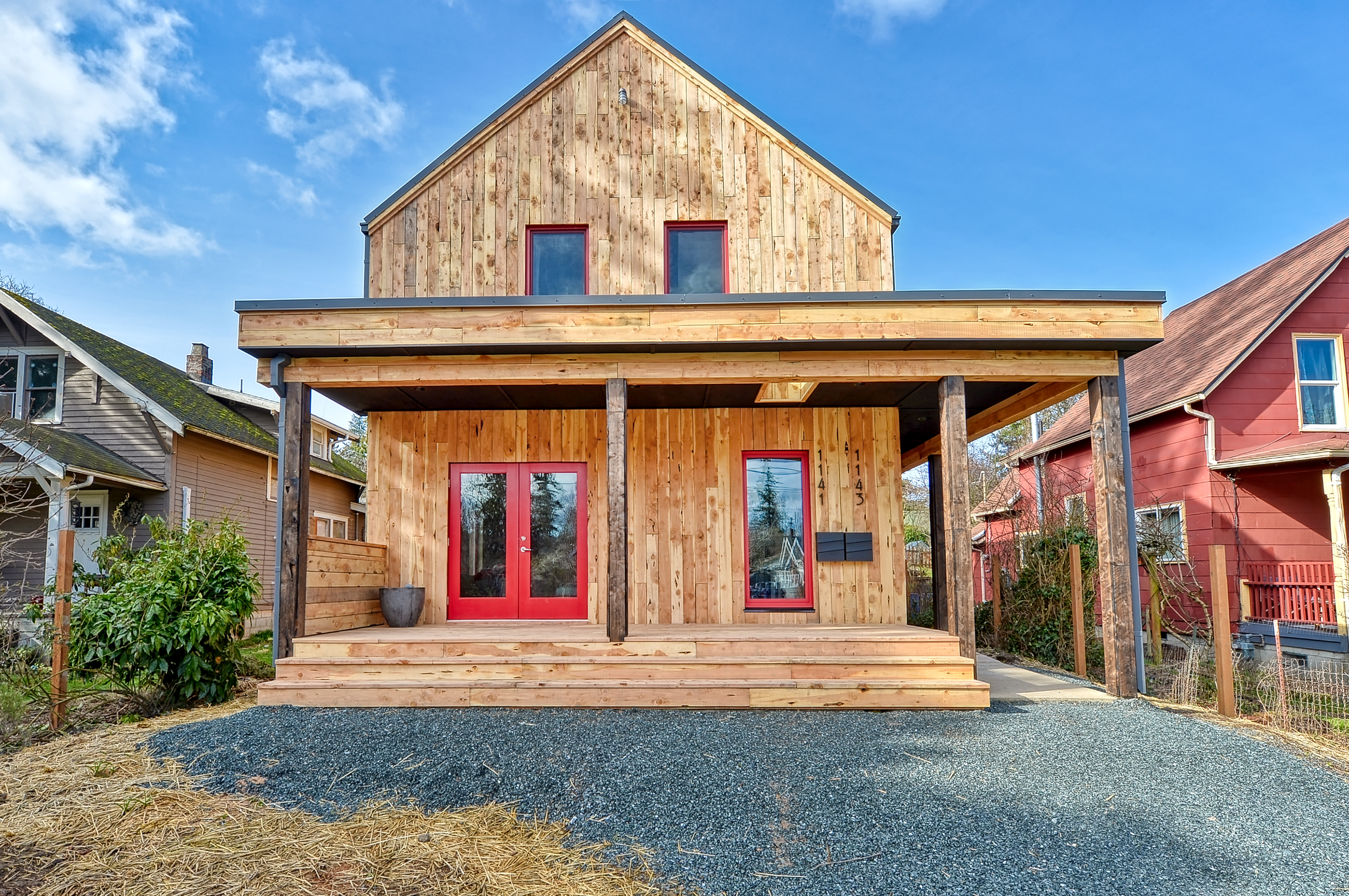
Right and Wrong Images

Source
A builder's guide describing hurricane-resistant reinforcements for gable ends.
Source
A builder's guide describing hurricane-resistant reinforcements for gable ends.
Source
A builder's guide describing hurricane-resistant reinforcements for gable ends.
Source
Report providing guidance on how to improve the wind resistance of existing residential buildings in Mississippi and across the Gulf Coast.

Source
A builder's guide describing hurricane-resistant reinforcements for gable ends.
Source
Source
Videos


More Info
References and Resources
*For non-dated media, such as websites, the date listed is the date accessed.
Contributors to this Guide
The following authors and organizations contributed to the content in this Guide.
Questions? Comments? Contact our webmaster.