

Scope
Roofs, roof projections, and dormers in new and retrofit construction can be strengthened by bracing with steel connectors and strapping to increase their resistance to uplift caused by high winds, hurricanes, and seismic conditions. Builders should consider installing the following:
- Install steel connectors, strapping, or screws at roof-to-wall connections to increase the uplift resistance along the load path.
- Secure roof sheathing to rafters or trusses using dense screw patterns, clips, and straps to increase the uplift resistance.
This guide will focus on the products and techniques relevant to new construction. Please refer to the Solution Center guide Retrofit of Existing Roofs for Hurricane, High Wind, and Seismic Resistance for products and techniques that are more relevant to retrofitting existing homes.
See the Compliance Tab for links to related codes and standards and voluntary federal energy-efficiency program requirements.
Description
For homes located in areas that experience high winds, hurricanes, and high levels of seismic activity, roofs, dormers, skylights, and other elements that project above the roof profile are vulnerable to damage. To protect a roof from the uplift forces, builders should consider installing the following: 1) metal structural connectors at framing joints, 2) sufficient bracing of walls and roof trusses, 3) increased fastening of roof sheathing, and 4) impact-rated glazing.
This guide will focus on the products and techniques relevant to new construction. Please refer to the Solution Center guide Retrofit of Existing Roofs for Hurricane, High Wind, and Seismic Resistance for products and techniques that are more relevant to retrofitting existing homes.
This guide will provide a discussion on dormer bracing because these structures are popular but they add many loads and stresses to the roof and structure of a home.
Metal Structural Connectors
For homes in high-wind areas, gone are the days when framing consisted simply of toe nailing and end nailing dimensional lumber together. Analyses of damaged buildings post-disaster have revealed that framing connections are usually the weak link causing a building to unravel during a storm or earthquake (FEMA 2010, 4.1). As a result, new standards have been developed requiring the use of steel structural connectors in the form of straps, ties, and screws to resist these extreme lateral, torsional, and uplift loads. In high-wind regions, special steel hardware connectors are used for most framing connections.
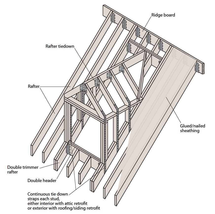
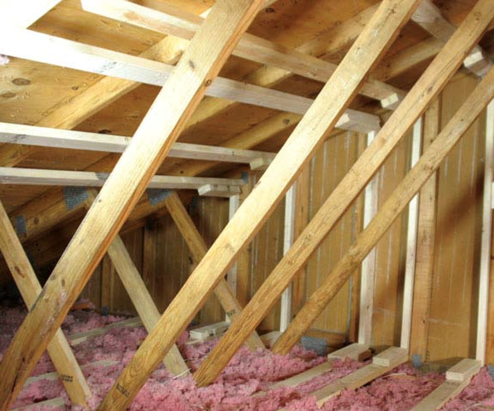
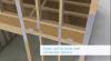
The use of steel connectors applies equally to the walls and roof of a dormer, which experiences extreme forces from wind pressures during a storm. An example of a dormer framed with steel connectors and strapping is shown in Figure 1 below. Additionally, dormers can add significant additional uplift and torsional loads to the main roof and the rest of the house. Turbulence and vortices from wind shedding off of a dormer can add additional forces to a building in addition to wind pressure (Cushman 2009).
The forces a structure is likely to experience are very region and location specific; therefore, it is imperative to research the building design conditions specific to the geographic location of the site and any special building codes that apply. Expected wind and earthquake loads impact the strength needed by the structural elements to withstand these loads and affect the required nail spacing patterns, wood sizing, and the number and types of structural connectors needed. The location also determines the level of corrosive weather exposure, such as salt spray, a connector will experience. This impacts the material and/or material coating selection.
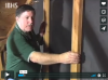
There are hundreds of different steel connectors, brackets, ties, straps, and screws, each designed to resist forces from specific directions and magnitudes. While there are likely multiple connectors suitable for a specific connection, care should be taken to ensure an appropriate one is selected. The connectors in concert with the framing members must form a continuous load path, transferring the loads to the ground. Refer to this 2015 IBHS video for examples of the metal connectors used to form a continuous load path. A general illustration of the type of metal connector used for a particular situation can be found in FEMA P-499, Home Builder's Guide to Coastal Construction: Technical Fact Sheet Series. Specific diagrams and descriptions illustrating the correct connector for a particular situation can be found on manufacturer’s websites. The metal connectors must be installed according to the manufacturer’s or engineer’s specifications.
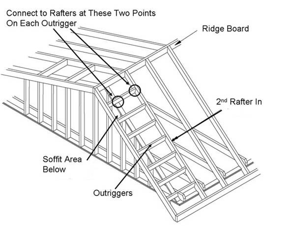
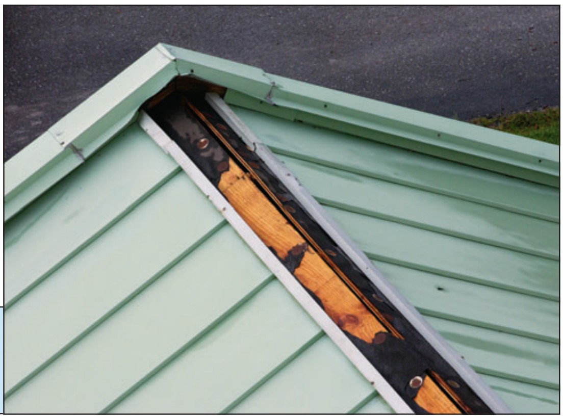
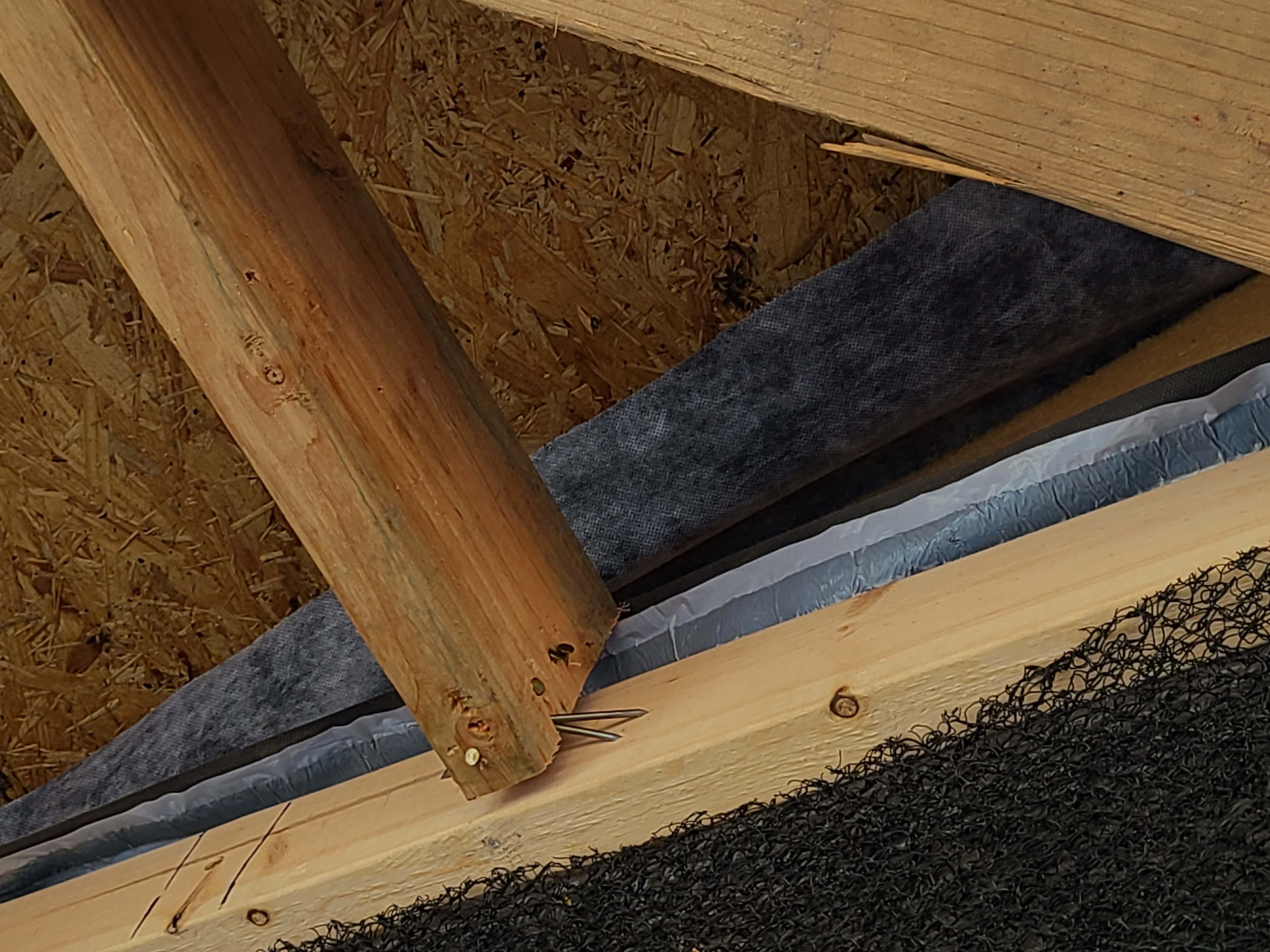
New connections are continuously being developed to strengthen connections that have been under-attended in the past. An example is the transition between the dormer roof and the main roof, which is framed with short jack rafters to create a valley. The compound miter angles of these rafters in the roof transition area necessitate a different kind of connector than straight rafters; thus, traditional rafter hangers cannot be used. Often there aren’t engineering specifications for the connection in this area or attention to ensure it is as strong and robust as all other roof connections. Because these rafters don’t have bearing/seat support, the lower nail fastener must provide that bearing. As a result, it is not uncommon to see split wood at this connection. Steel connectors have now been developed to address this connection and planning ahead can ensure a dormer is framed utilizing these connectors (Simpson Strong-Tie 2016). In high wind and hurricane regions, it is especially important to ensure that all parts of the roof are sufficiently strong since a partially damaged roof can result in significant water damage.
Since dormers add significant additional uplift and torsional loads to the main roof, care must be taken to ensure the roof framing around the dormer opening has sufficient strength to resist these loads. The 2015 International Residential Code (IRC 2015) provides framing guidelines for a roof or ceiling opening. It allows openings up to 4 ft to be created without needing extra framing members; thus, the header joist is permitted to be a single member the same size as the ceiling joist or rafter. A single header joist can be carried by a single trimmer joist if the header is located within 3 feet of the trimmer joist bearing. However, when the header joist span exceeds 4 feet, the trimmer joists and the header joist need to be doubled and of sufficient cross section to support the ceiling joists or rafter framing into the header. When the header joist span exceeds 6 feet, approved hangers are required for the header joist-to-trimmer joist connections. Tail joists over 12 feet long need to be supported at the header by framing anchors or on a ledger strip no less than 2 inches by 2 inches in cross-sectional area (IRC 2015 Section R802.9).
These guidelines should be treated as the minimum guidelines. For homes in locations with high wind, hurricane, and seismic conditions, adding additional bracing such as doubling the trimmer and/or headers may be required even for a small opening. The use of adhesives and metal strappings may be required to add strength and stiffness to framing. An engineer and local building codes should be consulted for location-specific guidance.
Source
Fact sheet describing how to install bracing to retrofit roof dormers for increased wind resistance.
Roof and Wall Bracing
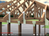
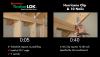
An increasing number of roofs are constructed using manufactured engineered trusses. These trusses can be designed with high heels to allow full insulation depth to be achieved along the eaves. However, raised heel trusses have been found in laboratory testing to experience high top cord and rotational displacement compared to low heel trusses during lab-simulated seismic events (NAHB Research Center 2011). The installation of blocking and continuous sheathing around the raised heel mitigated these effects, pointing to the need to ensure that these measures to brace raised heel trusses are implemented in the field.
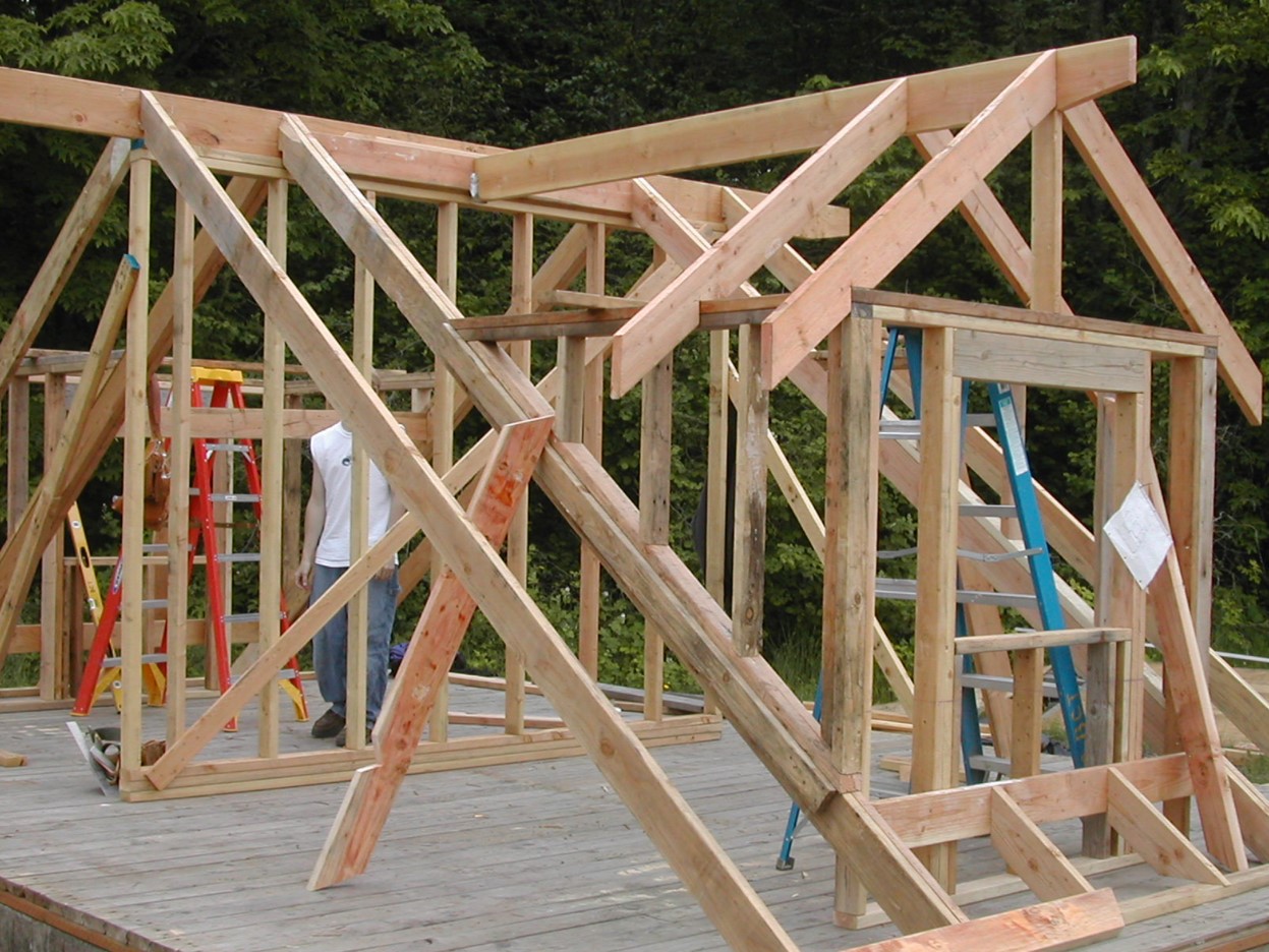
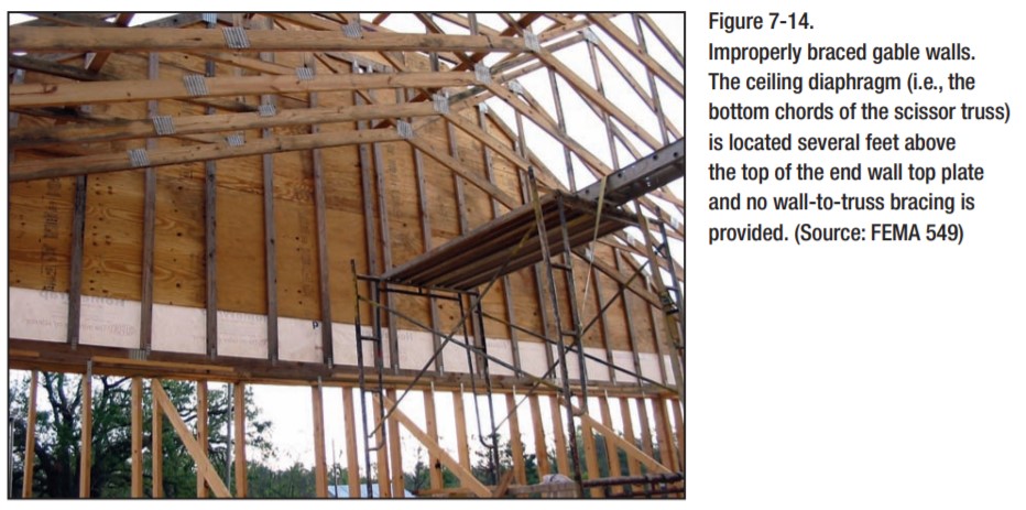
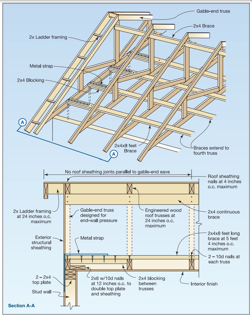
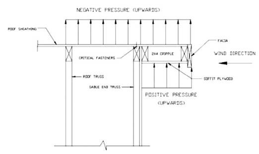
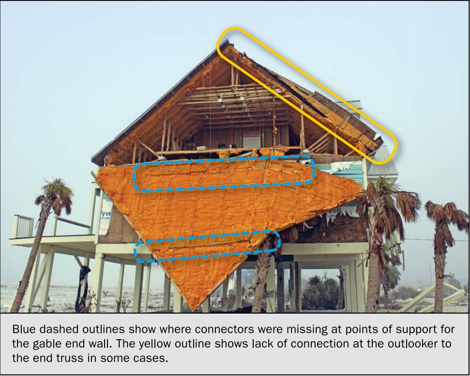
Trusses also need to be properly braced during installation to ensure safety and to ensure the trusses are installed straight and vertical. Trusses that are bowed or out of plum beyond the tolerances allowed by the manufacturer will fail to provide their designed strength because a truss is only strong when loads are applied in the directions it is designed for. To prevent trusses from buckling due to wind pressures, trusses need to be braced at the top and web cord with diagonal bracing. This bracing is especially important for securing the truss at the ends of a gable-style roof. Every truss package will include specifications and installation guides on where to place the required bracing.
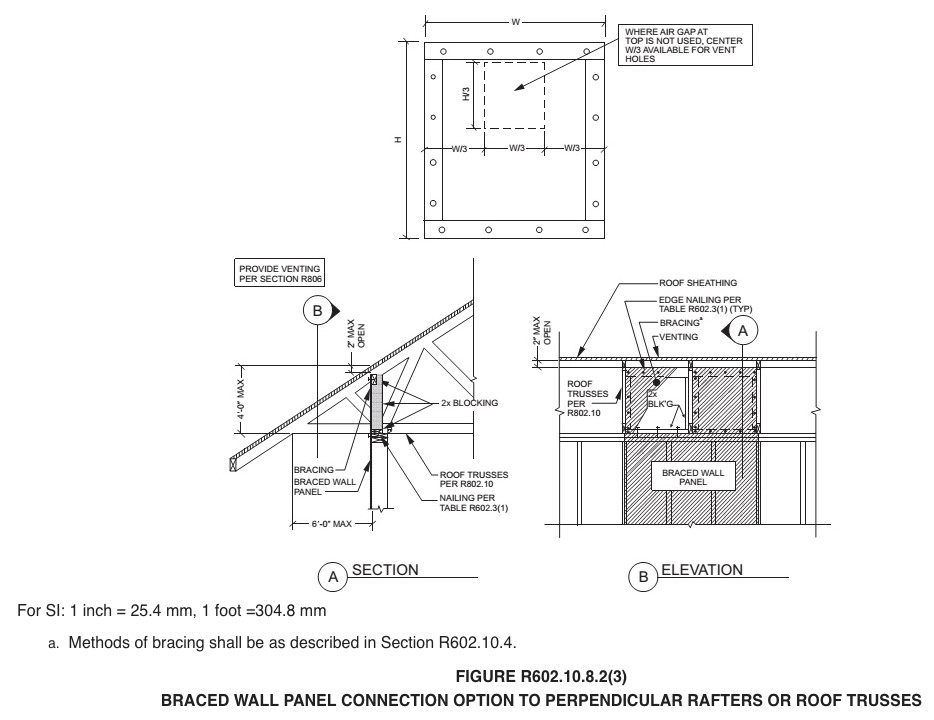
Wall bracing keeps a rectangular wall from shearing into a parallelogram shape when subjected to high winds and seismic loads. The amount of wall bracing needed, and the bracing method used is highly dependent on the location and shape of the building. Although a dormer only has to resist the forces imparted on its walls and roof, due to its height above the ground, it is subjected to higher wind speeds. The minimum length of qualifying braced wall is calculated based on seismic loads and then calculated again based on wind loads. The greater of the two values is selected. For a dormer with large window openings, there may be scenarios where there is not enough qualifying braced wall to satisfy the minimum requirements. If that is the case, an engineered design method is required. An engineer can specify specific steel connectors and braces that would result in the wall satisfying the required shear strength. The choice of wall bracing method is highly dependent on local codes. The International Residential Code (IRC) for example offers over a dozen choices, while the Wood Frame Construction Manual Guide to Wood Construction in High Wind Areas restricts the choice down to 3/8 in. or thicker OSB or plywood (IRC 2015; AWC 2015).
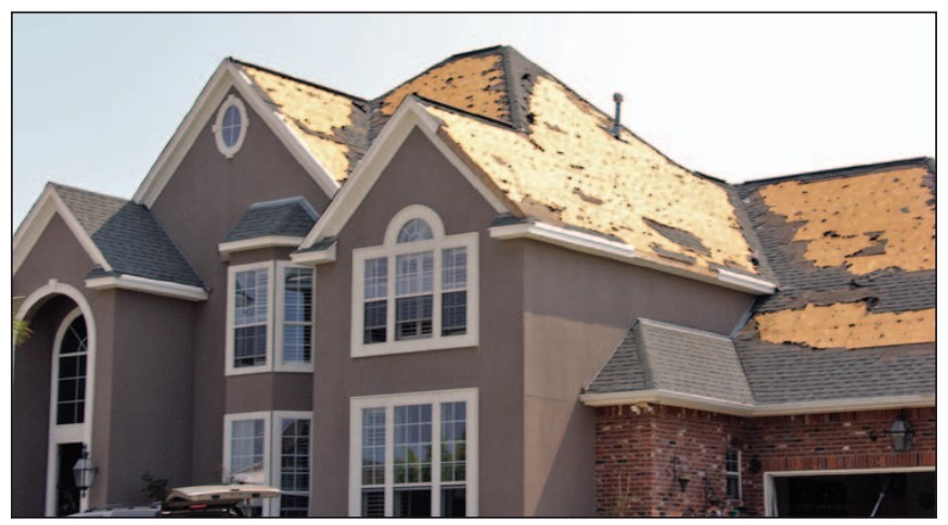
Secure Roof Sheathing
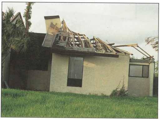
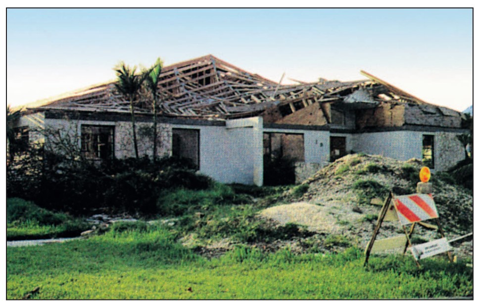
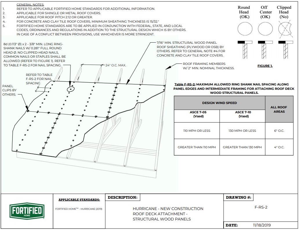
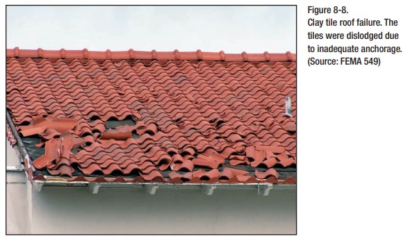
High winds lift a roof upward. This uplift force is transferred from the roofing material to the roof sheathing, then from the roof sheathing to the roof truss/rafters. Sheathing loss is one of the most common structural failures in hurricanes (FEMA 7 2010). To mitigate this problem, roofs in high wind locations typically use thicker sheathing panel, a tighter fastener spacing, and ring shank nails. It is extremely important to use the level of sheathing quality and fastener spacing specified for the design conditions for small roof sections such as dormer and porch roofs.
Generic building code specifications for roof assemblies in high wind regions that factor in shear and uplift forces can be found in Chapter 7, Roof Assemblies, of the Standard for Residential Construction in High-Wind Regions (ICC 2014).
Impact-Rated Skylights and Windows
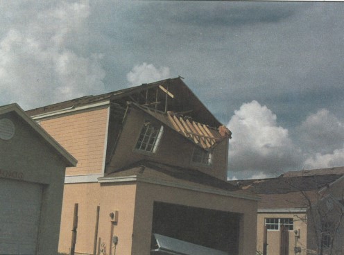
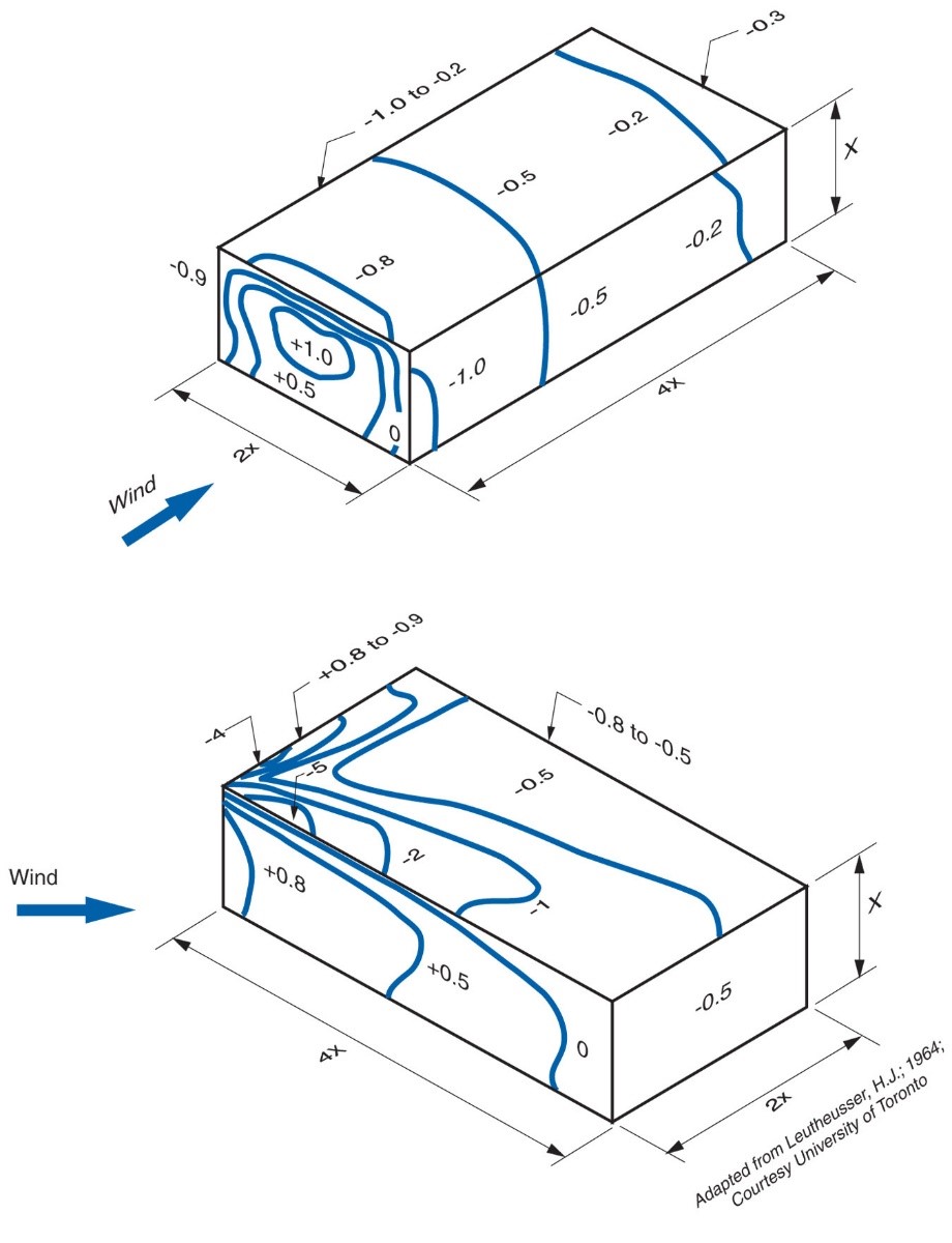
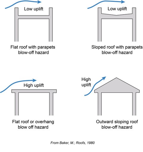
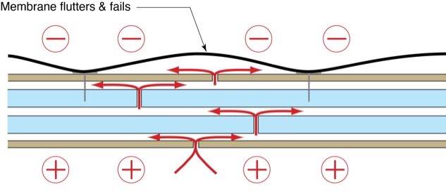
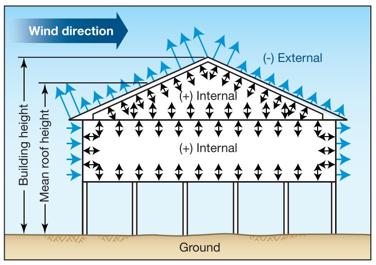
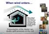
Hurricane-force winds can easily lift large heavy objects and turn them into high-velocity projectiles that can strike windows and skylights. A breach in the building envelope can not only cause severe water damage, it can significantly increase the wind loads on a structure. A breach in the building envelope on the windward side of the building will result in a significant positive internal pressure increase, which contributes to the uplift force on the roof. Homes are normally not designed to withstand these pressurization loads, which can cause a roof to blow off. This progressive failure can be prevented by protecting the glazing in the building envelope from being breached.
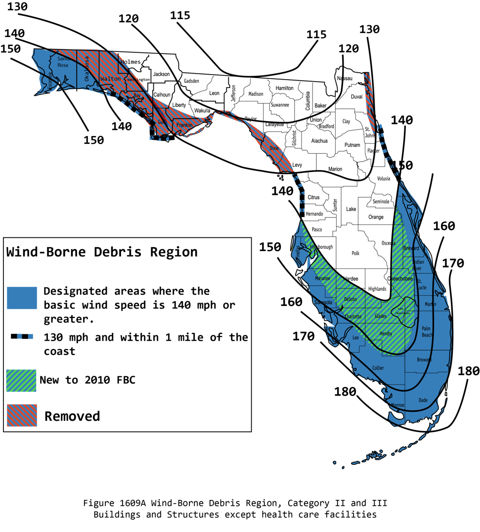
To protect against these flying projectiles, glazed openings (windows and skylights) should be protected by shutters or impact-resistant glass. The state of Florida for example requires storm shutters or impact-rated glass for homes located
- Within the “wind-borne debris region” where design speeds are greater than 120 MPH or
- Greater than 110 MPH if within one mile of the coast,
- Except the Florida panhandle where the region lies within 1 mile of the coast, and
- The “high velocity hurricane zone” of Miami-Dade and Broward counties.
The wind-borne debris region is defined as the “portions of hurricane-prone regions that are within 1 mile of the coastal mean high-water line where the basic wind speed is 110 mph (49 m/s) or greater; or portions of the hurricane-prone region where the basic wind speed is equal to or greater than 120 mph (54 m/s); or Hawaii” (FEMA P-762 2009).
However, even if a building is outside the required zone, it may be a good idea to have impact-resistant glass windows if it is located in a region that experiences high winds or hurricanes.
Glazed openings in buildings located in the windborne debris regions must be protected from windborne debris and that protection must meet the requirements of the Large Missile Test of an approved impact-resisting standard such as ASTM E1996 and ASTM E1886.
Impact-resistant glazing provides protection through the use of laminated glass or polycarbonate glazing systems. The use of physical-opening protection systems such as shutters, screens, or structural wood panels (as allowed by the IBC and IRC in certain hazard areas) is also a common means of achieving protection for glazing. Laminated glazing systems typically consist of assemblies fabricated with two (or more) panes of glass and an interlayer of a polyvinyl butyral (or equivalent) film laminated into a glazing assembly. After impact testing, the laminated glazing systems must resist the cyclic pressure tests of ASTM E1886 (FEMA P-762 2009).
How to Design and Specify Roof Connections in Locations Subject to High Winds, Hurricanes, and Earthquakes
Proper preconstruction design and specification is an essential step to success in designing a roof and roof projections that can withstand hurricane-force winds and seismic loads. This step includes:
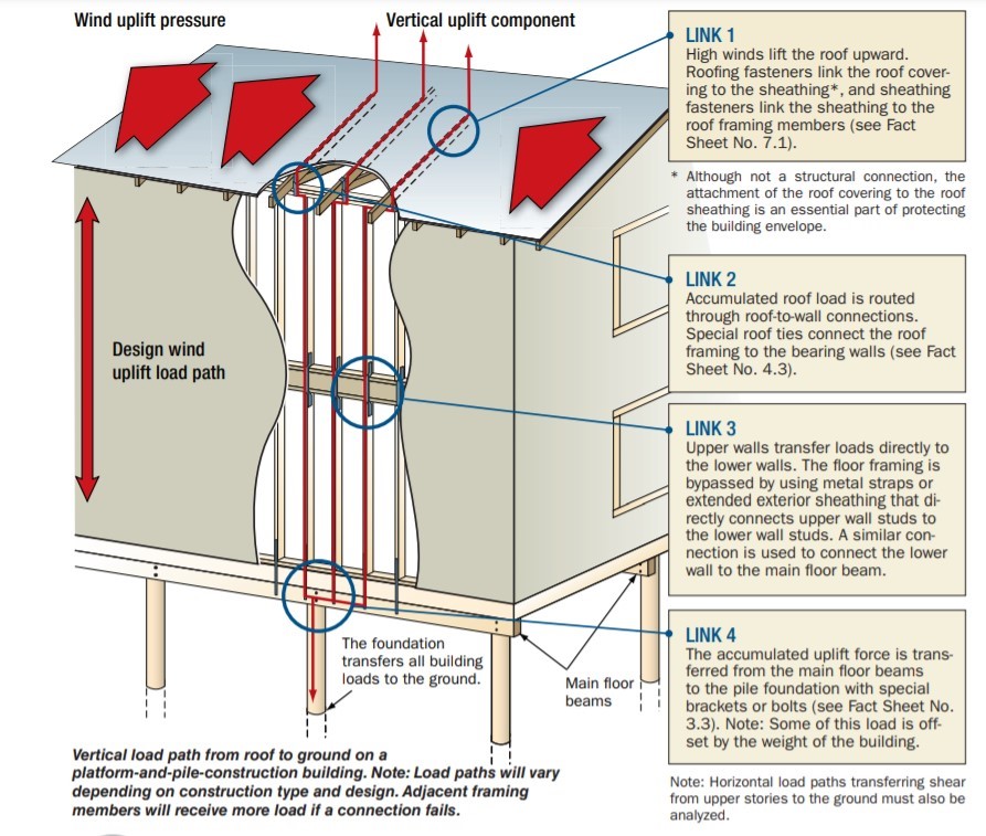
- Ensure proper load path analysis and specification of framing and hardware capable of resisting those loads. Load paths must successfully transfer the uplift, torsional, and shear loads created by high winds from the roof to the foundation. Each connection and structural member can be thought of as a link in a chain; the chain must be continuous and is only as strong as the weakest link. See the Climate tab and the Compliance tab for more explanation on determining wind loads for your location per the IRC.
- Ensure adequate qualifying braced/shear wall paneling to keep rectangular walls from turning into parallelograms. Refer to the Wall Bracing guide for more details on wall bracing.
- Mark up the plans to specify the sheathing nail patterns and connectors to control uplift forces in the load path.
- Ensure all metal connectors used are fit for purpose and the correct fasteners are used for each metal connector. Fasteners specifically designed to be used with metal connectors are colored coded or have numbers stamped into the nail head to allow post-installation verification. The fasteners must go into the designed locations in the metal connectors. If a pneumatic nailer is used, it must be fit for purpose such as a positive placement metal connector nailer that has a probe/guide tip to ensure the nails are placed in the designed locations.
How to Construct a Dormer in High Wind and Hurricane Regions:
- Frame the roof opening for the dormer such that it has sufficient strength. Refer to engineering design specifications and local building codes for guidance. In the absence of these specifications, refer to the local adopted version of the IRC.
- Ensure the dormer walls are sufficiently connected to the main roof using metal straps to reinforce the studs in a dormer wall to the roof framing. Refer to engineering design specifications and local building codes for guidance.
- Ensure the dormer roof-to-wall connections are sufficiently strong using hurricane ties or other suitable metal connectors. Refer to engineering design specifications, local building codes, and the manufacturer’s specifications for details on the installation spacing. In the absence of further restrictions refer to IRC Table R802.11, Rafter or Truss Uplift Connection Forces from Wind (allowable stress design) (pounds per connection).
- Ensure the roof sheathing is sufficiently secured to the rafters through the use of adhesives, metal clips, and a dense nailing pattern that is in conformance to engineering design specifications or local building codes.
- Install skylights and windows that are impact-rated.
Ensuring Success
Generic residential building plans often lack specifications on sheathing nail patterns and connectors to control uplift forces in a load path. This is because the plans are designed to be applicable for a wide variety of geographic locations. Care must be taken to mark up the plans to specify these elements for a home built at a location susceptible to high winds, hurricanes, and earthquakes. Many building codes offices have spreadsheets on their websites available for download for calculating wall bracing requirements for seismic and wind conditions. Since the 2012 version, the IRC has included Table R802.11, which details the pounds of uplift force a roof truss or rafter connector must withstand for a given design wind speed, roof pitch, and rafter/truss spacing.
During construction, it is essential that there is adequate inspection and supervision for work quality. Site supervisors should inspect the construction to ensure that the fastener schedule and materials specified are adhered to and that all fasteners connect with framing members.
Region
Generic residential building plans often lack specifications on sheathing nail patterns and connectors to control uplift forces in a load path. This is because the plans are designed to be applicable for a wide variety of geographic locations. Care must be taken to mark up the plans to specify these elements for a home built at a location susceptible to high winds, hurricanes, and earthquakes. Many building codes offices have spreadsheets on their websites available for download for calculating wall bracing requirements for seismic and wind conditions.
High Wind Areas
Since the 2012 version, the IRC has included Table R802.11, which details the pounds of uplift force a roof truss or rafter connector must withstand for a given design wind speed, roof pitch, and rafter/truss spacing. During construction, it is essential that there is adequate inspection and supervision for work quality. Site supervisors should inspect the construction to ensure that the fastener schedule and materials specified are adhered to and that all fasteners connect with framing members.
Wind speed maps contain contours specifying the wind speed a building must be designed to withstand for a specific location. Homes located within the wind-borne debris region have special design requirements. These maps occasionally change due to new data stemming from lessons learned from storms. For example, the wind speed map of Florida shown in Figure 1 shows the expanded region of homes that are subject to the design requirements of the wind-borne debris region shaded in green; buildings located in the area shaded in red were removed from being subjected to the designs requirements of the wind-borne debris region.
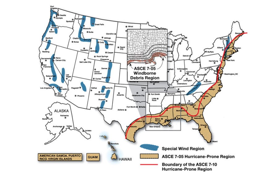
Expanding the range of the wind speed map to the entire United States shows many regions that have special design requirements due to high winds as shown in Figure 2.
Source
Report providing guidance on how to improve the wind resistance of existing residential buildings in Mississippi and across the Gulf Coast.
To give some background to Figure 2, ASCE 7-05 defines windborne debris regions as hurricane-prone regions located within 1 mile of the coastal mean high water line where the basic wind speed is equal to or greater than 110 mph (and in Hawaii) and inland in hurricane-prone regions where the basic wind speed is equal to or greater than 120 mph. In ASCE 7-10, the windborne region is defined as locations where the wind speed is greater than 130 mph within 1 mile of the coast or any location inland where the wind speed is 140 mph or greater. Beginning in the 2012 International Building Code and International Residential Code, ASCE 7-10 is required for calculating the wind uplift pressures on buildings and other structures. Rather than using one design wind speed for all buildings, ASCE 7-10 assigns one of three design wind speeds for a location depending on the building's importance classification. Although ASCE 7-10 is more precise, the result is an actual reduction in geographic area that is subject to the building requirements of the hurricane-prone zone as shown in Figure 2.
Seismic Areas
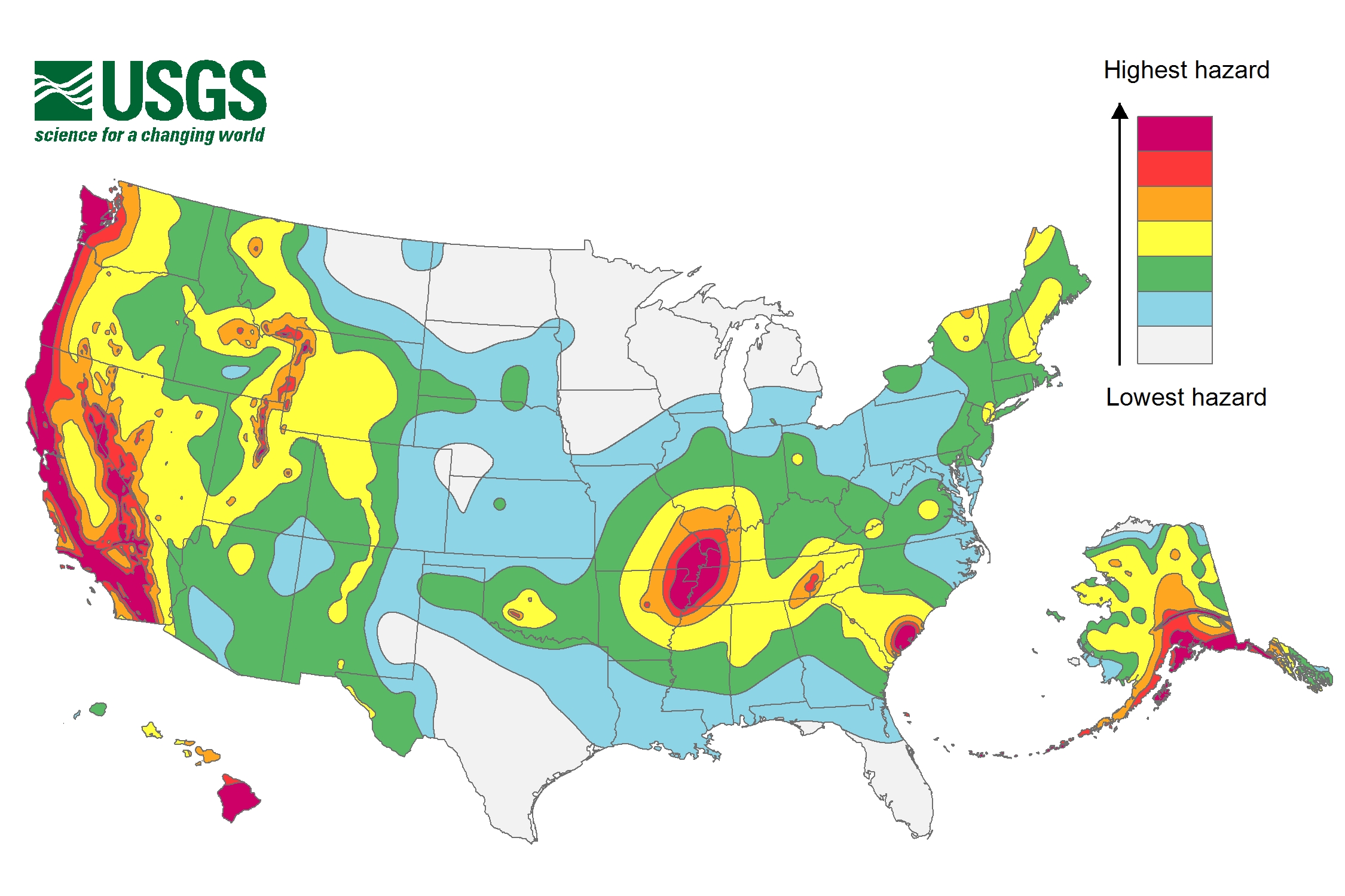
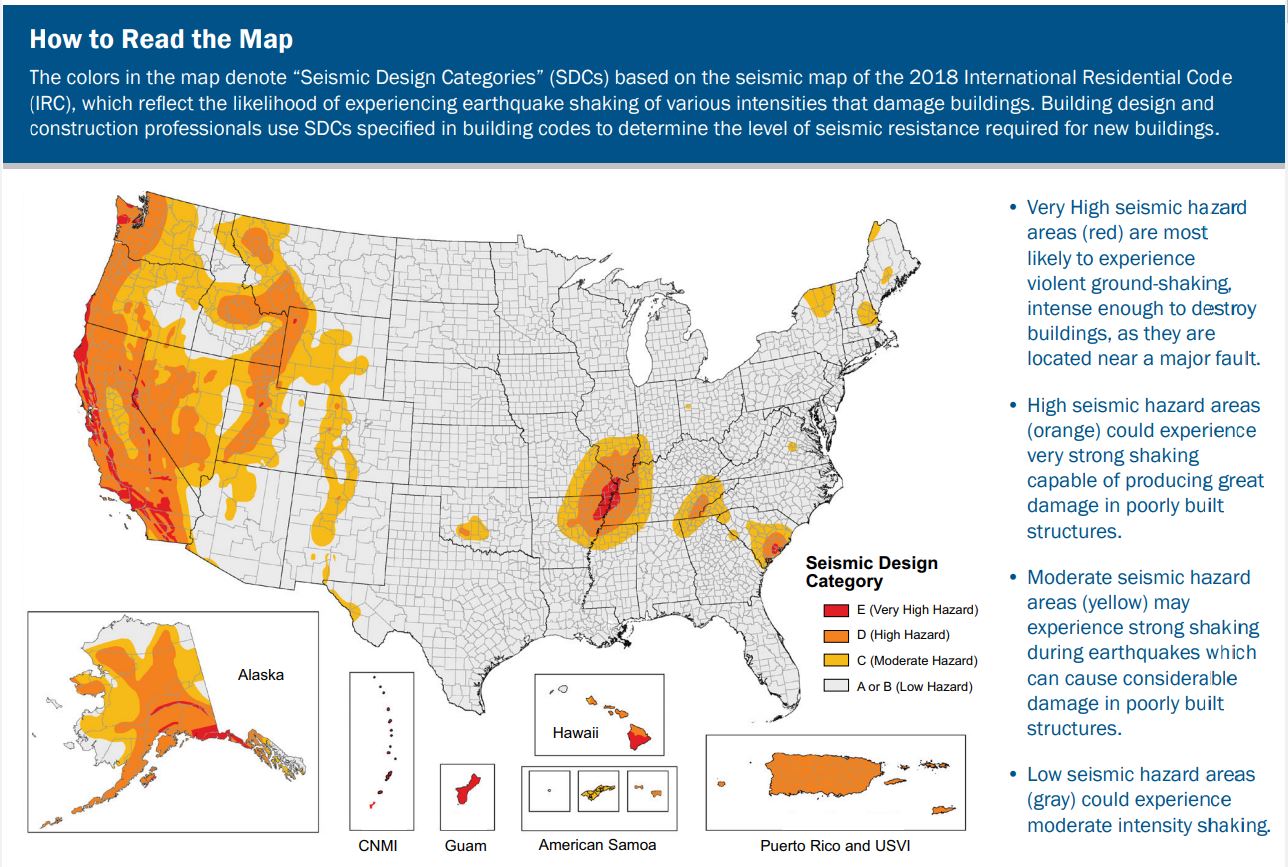
In addition to designing a building that can withstand high winds, the prescriptive design guidelines in the International Residential Code (IRC) also take a building’s seismic risk into account as shown in Figure 3. The International Code Council (ICC) assigns the seismic design category designation for a location based on research by the U.S. Geological Survey, which is summarized into probabilistic maps of the expected number of damaging earthquakes around the United States as shown in Figure 3. The IRC contours the United States into seismic design categories, from low risk to high risk as shown in Figure 4, which designates the categories by letter: A, B, C, D0, D1, D2, and E, with A designating the lowest risk and E designating areas with the highest risk. The IRC has design guidelines for categories A through D2 as well as scenarios for when a building in design category E can be reassigned to category D2. If a building located in design category E cannot be reassigned to category D2 then it must be designed using the International Building Code (IBC), not the IRC.
Source
A colored map showing seismic zones across the United States, ranging from lowest to highest seismic hazards.
Source
2018 edition of code for residential buildings that creates minimum regulations for one- and two-family dwellings of three stories or less, bringing together all building, plumbing, mechanical, fuel gas, energy and electrical provisions for one- and two-family residences.
Training
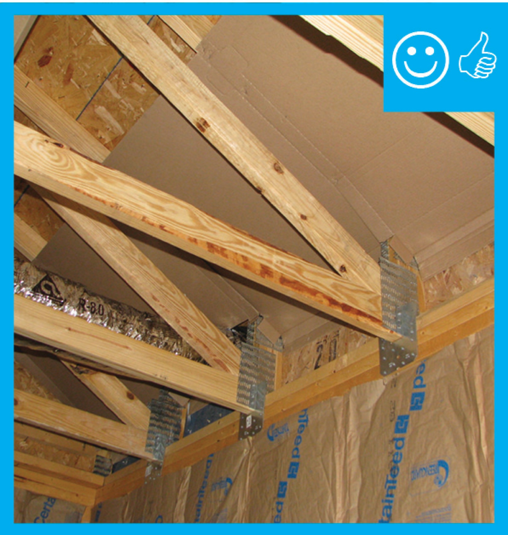
Right and Wrong Images

Source
Source
Source
Guide describing details that serve as a visual reference for each of the line items in the Thermal Enclosure System Rater Checklist.
Source

Source
Document containing recommendations on how to brace roofs and gable end walls based on lessons learned from analyzing the destruction from hurricane Andrew.
Source
Report providing guidance on how to improve the wind resistance of existing residential buildings in Mississippi and across the Gulf Coast.
Source
A builder's guide describing hurricane-resistant reinforcements for gable ends.
Source
Guide discussing observations, recommendations, and technical guidance as a result of Hurricane Katrina
Source
A builder's guide describing hurricane-resistant reinforcements for gable ends.
Source
Volume II of a two-volume report providing a comprehensive approach to design, construction, and renovation of homes located in coastal environments.
Source
Document containing recommendations on how to brace roofs and gable end walls based on lessons learned from analyzing the destruction from hurricane Andrew.
Source
Source
Source
Volume II of a two-volume report providing a comprehensive approach to design, construction, and renovation of homes located in coastal environments.
Source
Source
Website describing the Insurance Institute for Business & Home Safety (IBHS)'s Fortified Home program which offers home builders standards and guidance for constructing and renovating homes for increased disaster resistance.
Source
Volume II of a two-volume report providing a comprehensive approach to design, construction, and renovation of homes located in coastal environments.
Source
Report containing 37 fact sheets that provide technical guidance and recommendations concerning the construction of coastal residential buildings.
Source
Report containing 37 fact sheets that provide technical guidance and recommendations concerning the construction of coastal residential buildings.
Source
Document containing recommendations on how to brace roofs and gable end walls based on lessons learned from analyzing the destruction from hurricane Andrew.
Source
2018 edition of code for residential buildings that creates minimum regulations for one- and two-family dwellings of three stories or less, bringing together all building, plumbing, mechanical, fuel gas, energy and electrical provisions for one- and two-family residences.
Source
A builder's guide describing hurricane-resistant reinforcements for gable ends.
Source
Article describing construction best practices to help reduce the wind-induced pressure loads on a low-rise building during a hurricane.
Source
A builder's guide describing hurricane-resistant reinforcements for gable ends.
Source
Source
Report containing 37 fact sheets that provide technical guidance and recommendations concerning the construction of coastal residential buildings.

Source
Guide describing the requirements by FORTIFIED Home™ for improving the home's resistance in severe thunderstorms, straight-line wind events, and high winds at the outer edges of tornadoes.
Source
Guide describing sound mitigation measures to lower building natural disaster vulnerability to assist local officials and community decision makers in coastal areas.
Source
FEMA Mitigation Assessment Team Report describing damages from Hurricane Michael in Florida in Oct. 2018 and recommendations for future hurricane preparedness.
Source
Volume II of a two-volume report providing a comprehensive approach to design, construction, and renovation of homes located in coastal environments.
Source
Source
Source
Videos


Compliance
International Residential Code (IRC)
Metal Connector and Fastener Manufacturer’s Manuals
Retrofit
Information regarding bracing roofs in existing homes can be found in the guide Retrofit of Existing Roofs for Hurricane, High Wind, and Seismic Resistance.
More Info
References and Resources
*For non-dated media, such as websites, the date listed is the date accessed.
Contributors to this Guide
The following authors and organizations contributed to the content in this Guide.
Questions? Comments? Contact our webmaster.