

Scope
Measure mechanical system airflow rates using reliable accurate equipment and methods.
- Select a recommended location to make flow measurement that will result in acceptable accuracy.
- Select an airflow measurement device with acceptable accuracy for the application.
- Determine whether alternative airflow methods and tools not covered in test standard ANSI/RESNET/ICC 380-2019 are suitable.
To see test standard ANSI/RESNET/ICC 380-2019, which covers whole-house mechanical ventilation airflow measurement methods, see the Standard for Testing Airtightness of Building, Dwelling Unit, and Sleeping Unit Enclosures; Airtightness of Heating and Cooling Air Distribution Systems; and Airflow of Mechanical Ventilation Systems.
For an overview of whole-building ventilation systems and airflow requirement guidelines, see the description tab of the Building America Solution Center guides Whole-House Ventilation Strategies for New Homes and Whole House Ventilation Strategies for Existing Homes guides.
See the Compliance tab for links to related codes and standards and voluntary federal energy-efficiency program requirements.
Description
Verifying the delivery of adequate ventilation in a whole-house mechanical ventilation (WHMV) system is critical to the function of the WHMV system as well as to the health of the building occupants. Several studies in different parts of the country have consistently shown that many homes with WHMV systems fail to deliver adequate ventilation (Sonne et al. 2016, Eklund et al. 2014, and Lubliner et al. 2002). Poor design of the WHMV is one of many common causes of inadequate ventilation.
Energy conservation efforts have resulted in tighter homes with better control over air leakage, which has led to reduced natural ventilation to the point where WHMV is needed to ensure adequate indoor air quality. WHMV can be provided through four common styles: exhaust only, supply only, central fan integrated supply (CFIS) (a form of supply only), and balanced, which include energy recovery ventilators (ERV) or heat recovery ventilators (HRV). More details, including the pros and cons of each of these different systems, can be found in the Solution Center guide Whole House Ventilation Strategies for New Homes.
Whole-House Mechanical Ventilation Measurement Methods
ANSI/RESNET/ICC Standard 380-2019 identifies several methods and equipment types used to measure the volumetric airflow rate. These include:
- Air capture flow hood
- airflow resistive device
- in-line airflow measurement station
- inserted air velocity device
- integrated diagnostic tool
- bag inflation.
ANSI/RESNET/ICC Standard 380-2019 specifies accuracy requirements for each type of measurement method and where on the WHMV system it may be used. More details on Standard 380 may be found online. For detailed information on accessing ventilation equipment to conduct airflow tests using any of the equipment described below, see the guide: Testing of Mechanical Ventilation Systems.
Airflow Capture Hood - An airflow capture hood is a hand-held device that has an enclosure with two open ends through which airflow is directed past an airflow sensor. These devices may be passive or powered.
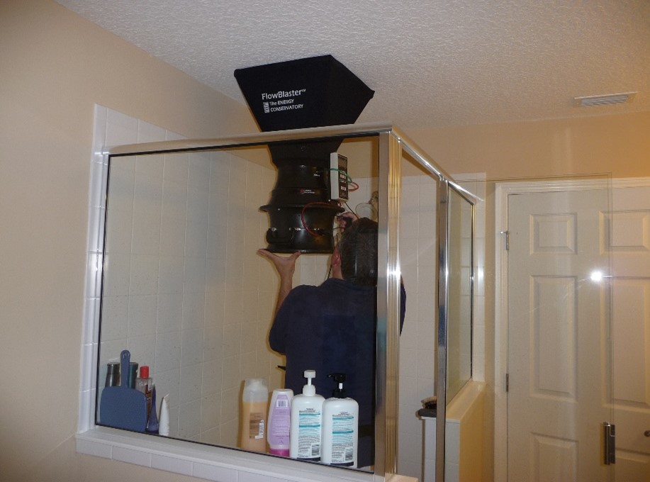
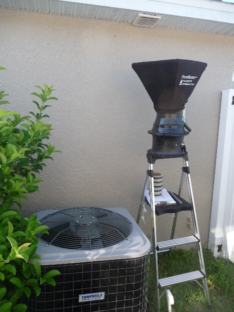
Passive Air Capture Flow Hood - A hood that is applied at an air terminal or grille that transfers air through a metering device capable of measuring volumetric airflow (Figure 1). This type of hood has no motor or fan and air moves through it due to the mechanical force of air being measured at the terminal.
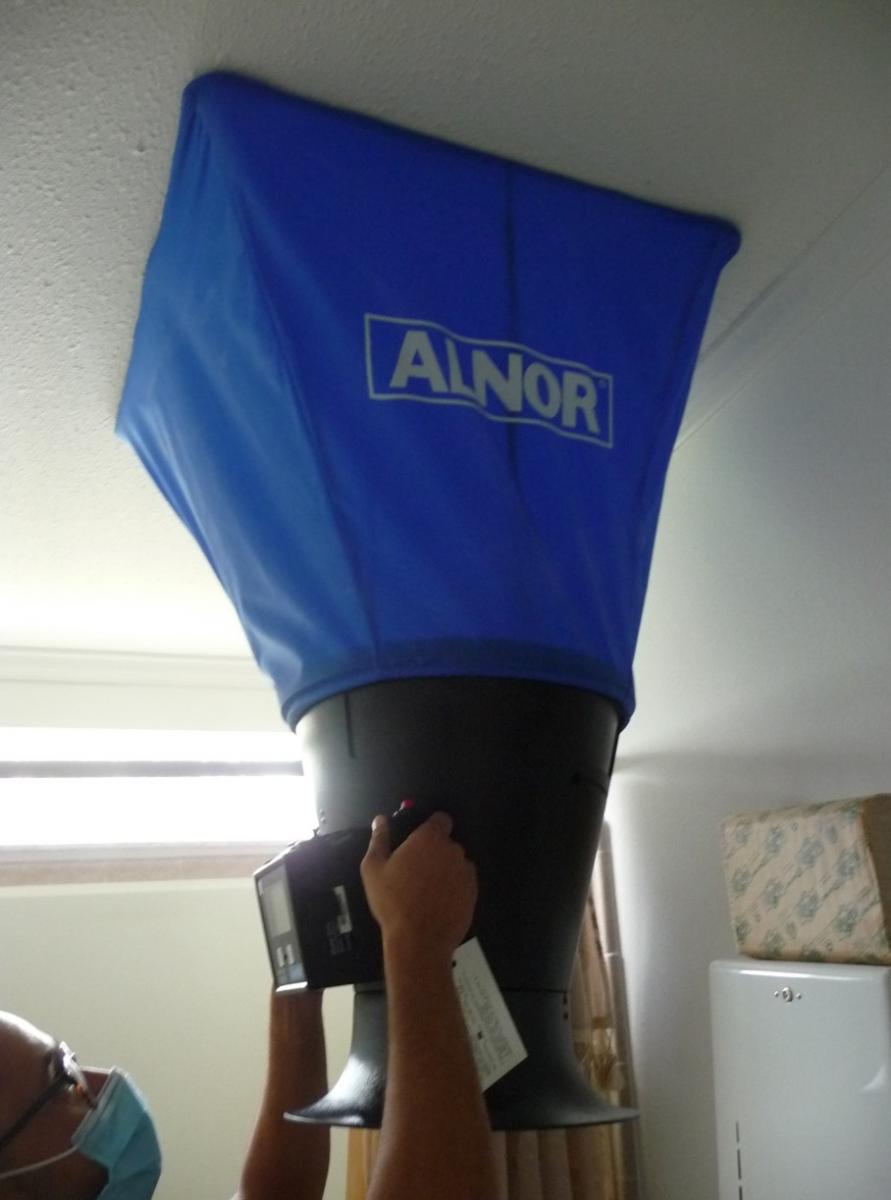
Powered Air Capture Flow Hood - This device is similar to a passive flow hood except that it has a speed-adjustable fan attached that eliminates changes in static pressure within the WHMV that are caused by taking the flow measurement and it is therefore more accurate in most cases (Figure 2).
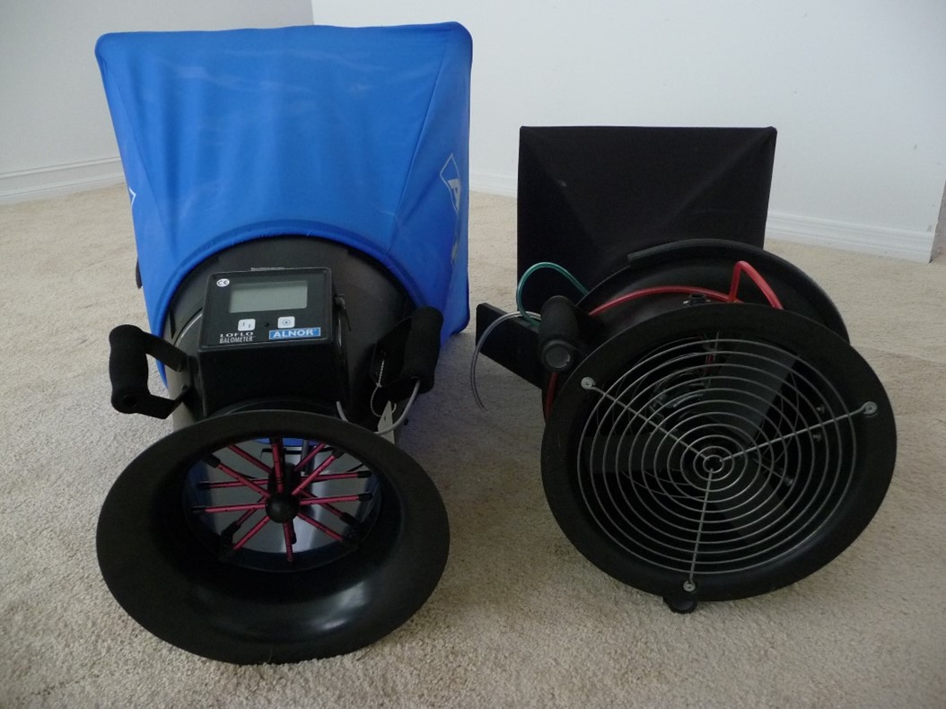
Figure 3 shows the passive and powered flow hoods side by side for comparison.
Airflow Resistive Device
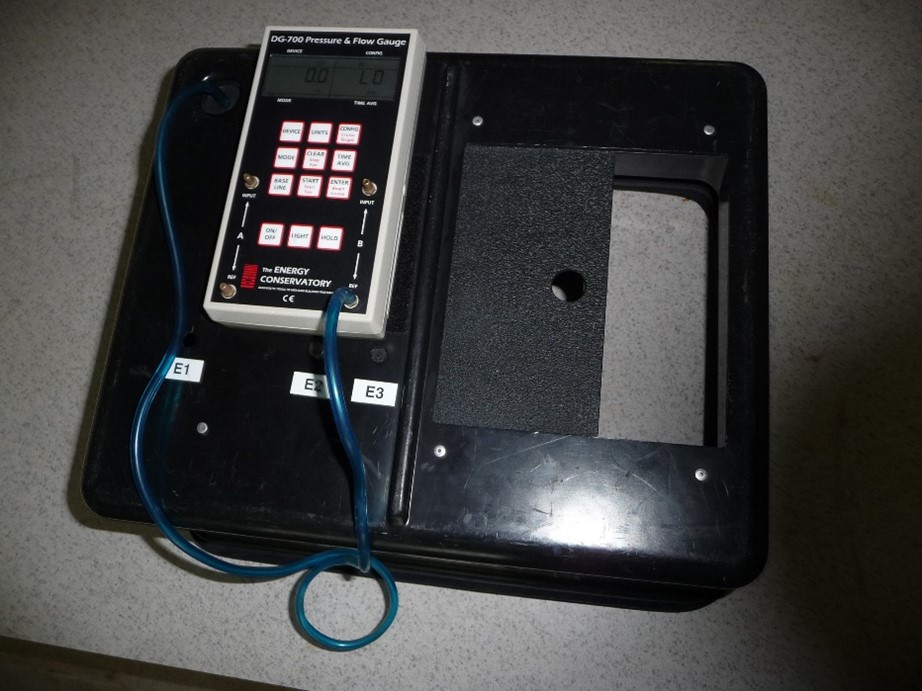
This airflow measurement device may also be referred to as an “airflow box.“ The airflow box is essentially a box with an adjustable opening of known dimensions on one side and at least one air pressure port. ANSI/RESNET/ICC Standard 380 only permits this device to be used at the air terminal inlets of WHMV systems having only one air inlet terminal. With the device secured around the terminal, air is pulled into the box through the movable opening. The static pressure difference inside the resistive device, with reference to the surrounding room or space, is measuredusing a manometer (Figure 4) and used to calculate the airflow rate using the device manufacturer calibration or an equation that correlates the airflow rate to the differential pressure measurement.
Do not use this type of device when more than one inlet terminal is connected to the WHMV system. The pressure inside the capture box with reference to the room should be measured. This method should be limited to meet the pressure range specified by the manufacturer or between 1 to 8 Pa (0.032 in. water) if no manufacturer limit is stated.
ANSI/RESNET/ICC Standard 380-2019 Inline Installed Airflow Measurement Station
There are different types of in-line airflow stations that can be integrated into the WHMV duct to measure the WHMV air flow. Each station type requires an air pressure measurement and uses a unique calibration equation to calculate airflow based on the duct cross-sectional area specific to the particular station where the measurement is taken. Standard 380-2019 is written for devices that represent the average velocity pressure across the entire WHMV duct cross-section. These types of airflow stations would have several pressure sample points that manifold to two pressure ports that would measure average velocity pressure and average static pressure. A manometer with maximum error of 1% of reading or 0.25 Pa, whichever is greater, is used to measure one port with reference to the other.
Static Pressure Differential Inline Airflow Measurement Stations
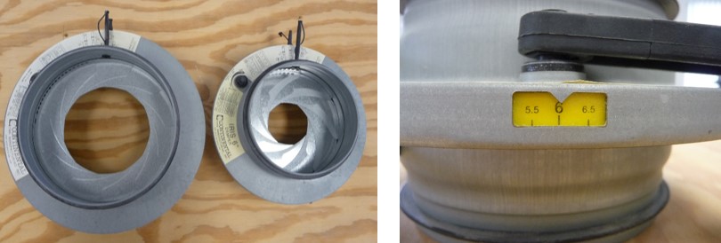
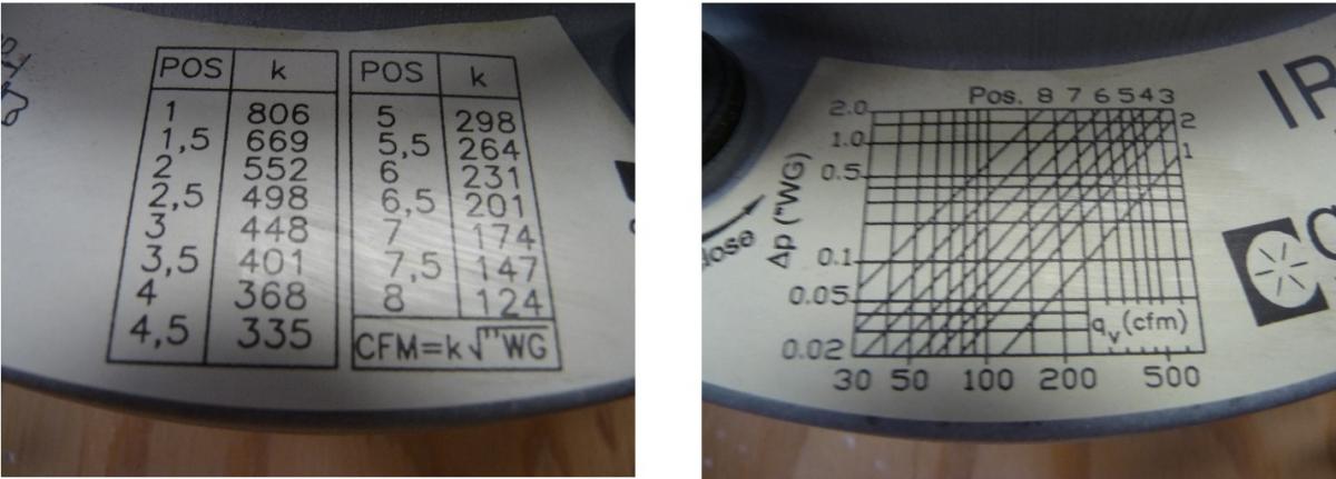
Some flow stations take a simple static pressure measurement across an in-line aperture of known area. Manufacturers of such stations provide calculations to convert the pressure to airflow. One example is an iris damper. The damper can be adjusted to open and close much like the iris of an eye. This type of device operates somewhat like an in-line airflow restrictive device. Figure 5 shows an example of two different sized flow dampers and a close-up view of the aperture setting window, which indicates the size of the damper opening and is part of the airflow calculation. Figure 6 shows a close-up of the manufacturer calibrations for different aperture setting positions (shown as POS on the label). The label on the left can be used to calculate airflow when POS and static pressure in inches water gauge (W.G.) are known. The label on the right side of Figure 6 shows a chart that can also be used to determine airflow rate.
Anemometer Velocity-Based Measurement - Air velocity can also be measured with small-profile anemometers that can be inserted into a mid-stream duct section (Figure 7). Anemometers may be of a rotating vane or hotwire design. These instruments are not recognized by Standard 380-2019. This method requires several measurements at very specific locations within a duct cross-section (i.e., duct traversing) and should only be used by experienced professionals. Measurement error greater than the manufacturer’s stated accuracy can occur when the anemometer is not oriented correctly, is not placed at appropriate traverse measurement locations, or is placed too close to duct bends. More information on how to conduct measurements with these instruments can be found below in the section “How to Calculate Airflow Rate from a Velocity Probe Measurement.”
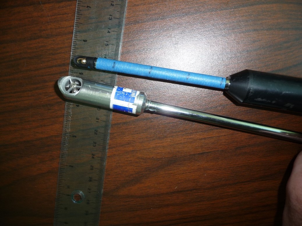
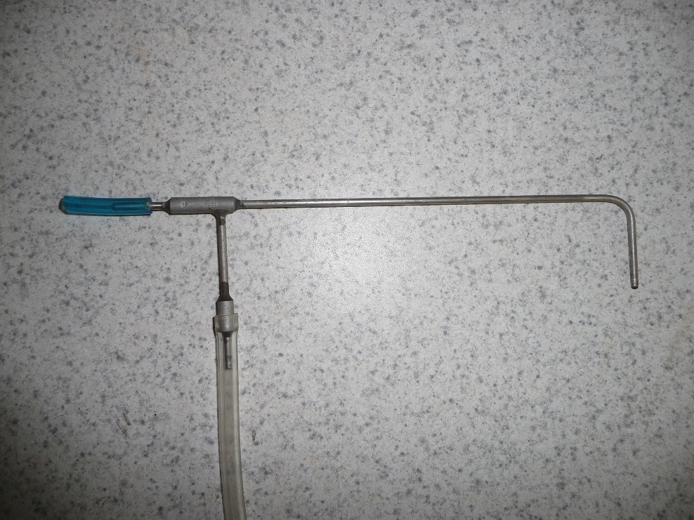
Pitot Tube Pressure-Based Measurement
A pitot tube is a device that operates based on pressure measurements and can be used to determine airflow (Figure 8). The pitot tube is not specifically recognized in Standard 380-2019, but it is commonly used by test and balance practice in commercial building ducts. This method requires at least 12 measurements at very specific locations within a duct cross-section (i.e., duct traversing) and should only be used by experienced professionals. Significant error greater than 30% of the reading can easily occur if measurement locations and the orientation of the pitot tube probe into the air stream are not correct. Even under best-practice and maximum manometer errors of 1% of reading or 0.25 Pa (0.0010 in WG), the error of the manometer reading could result in an error of airflow of about 13%. This error example assumes a round 6-inch duct with true airflow of 50 cfm and 255 ft/min velocity. The velocity pressure is very low for this common duct arrangement and would only be about 1 Pa (0.00040 in WG). The maximum manometer error allowed by Standard 380-2019 is 1% of reading or 0.25 Pa, whichever is greater. In this specific case, the maximum permitted manometer error would be 0.25 Pa. For reference, an under-measurement error of 0.25 Pa would result in a 0.75 Pa reading, which would equate to only 43 cfm instead of 50 cfm.
Factors that May Affect WHMV Flow Accuracy
There are various potential factors that can affect the accuracy of airflow measurements. Flow test equipment should be maintained and calibrated at required intervals and should only be used for the application it was designed for. Factors that may impact airflow accuracy include the following:
- Windy conditions
- The air velocity vector (direction and magnitude) going into a flow measurement device such as a flow hood or other air pressure-sensing device.
- A flow device that causes air to flow through an area undersized for the flow rate being measured causing restriction to the WHMV flowrate.
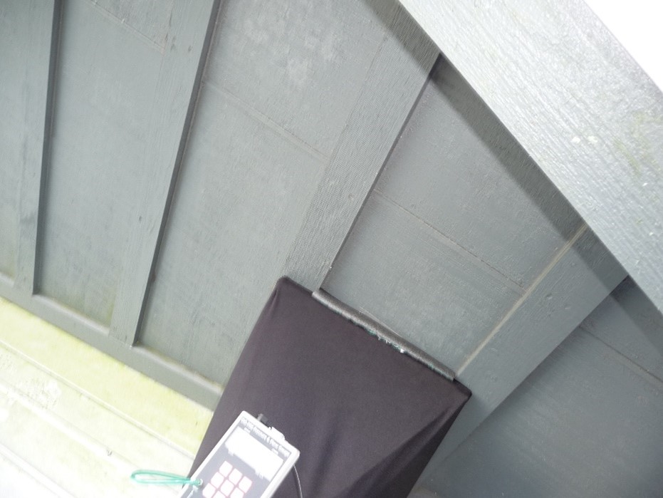
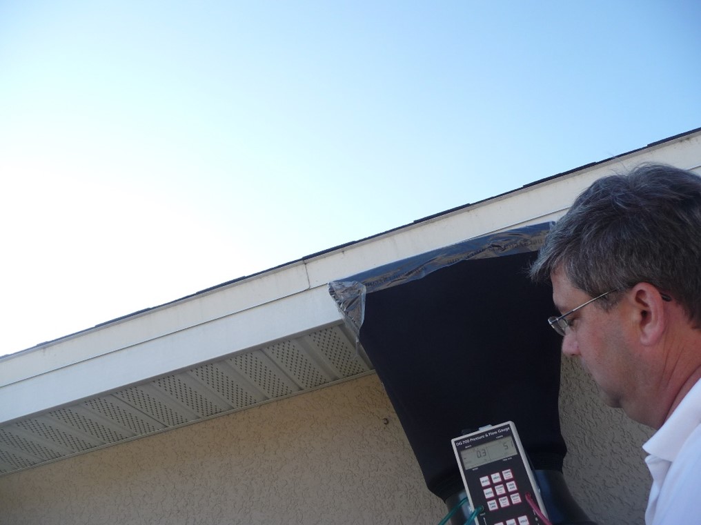
- Poor fit of airflow hood around the grille, particularly on an uneven backing surface or vented surface such as a vented soffit.
- Measuring airflow rates at or beyond the boundaries of the designed flow rate or velocity.
- Damaged equipment or sensor drift.
- Improper use of equipment (i.e., not following manufacturer instructions) or measurements being done by untrained technicians.
- Using equipment that is out of calibration or uncalibrated.
Selecting a WHMV Airflow Measurement Method
- Determine which air flow measurement method to use based on the ventilation system installed, weather conditions, and accessibility of measurement locations. Look for indoor grille locations that are sheltered from wind affects and inclement weather. If indoor grille locations are not available, make outdoor measurements when there is little to no wind, if possible.
- If already installed, use an airflow measurement station. Such devices should be capable of measuring airflow with an accuracy of 10% of reading or 5 cfm, whichever is greater. Do not use such devices if the airflow measurement station is not installed in accordance with manufacturer specifications or ANSI/RESNET/ICC 380-2019. There should be a smooth, straight section of duct ideally equal to 8.5 duct diameters upstream and 1.5 diameters downstream of the measurement station. This requirement can make it difficult to find a suitable measurement location. Some manufacturers may only require 4 duct diameters upstream and 1 duct diameter downstream.
- Only use an airflow resistive device at inlet grilles (such as an indoor exhaust grille). Do not use this type of device when more than one inlet terminal is connected to the WHMV system. The pressure inside the capture box with reference to the room should be measured. This method should be limited to meet the pressure range specified by the manufacturer or between 1 to 8 Pa (0.032 in. water) if no manufacturer limit is stated.
- Powered flow hood measurement accuracy is typically better than passive flow hood accuracy, particularly at higher flow rates and at outlet terminals; however, both hoods still have limitations on the range of flowrates and neither type of flow hood should be used outdoors during very gusty winds or wind greater than about 10 miles per hour. Passive flow hood accuracy may be impacted by the air velocity vector and backpressure created during measurement. For instance, passive flow hoods are more susceptible to error at outlet terminals compared to an inlet terminal due to more turbulent airflow from outlets compared to inlet terminals. Powered flow hood accuracy is not as susceptible to air velocity vector and does not alter the WHMV static pressure and flowrate during measurement.
- When there is no suitable inlet/outlet terminal or installed flow station available, use of an air velocity device designed for insertion into a small hole placed in the WHMV duct is recommended. An airflow instrument duct penetration should not be made into flexible (or non-rigid) ducts. The liners of flexible ducts can develop long tears from the hole that will result in duct leakage. If there is no rigid section of duct available, a contractor should cut out approximately 5 feet of flexible duct and replace with rigid, straight smooth duct. ANSI/RESNET/ICC Standard 380-2019 does not provide guidance on how to make manual velocity measurements using probes. Further details on how to conduct this flow method are detailed in the next section.
How to Calculate Airflow Rate from a Velocity Probe Measurement
ANSI/RESNET/ICC Standard 380-2019 requires that air velocity measurement devices limit measurement error to 10% or 5 cfm, whichever is greater. Standard 380-2019 does not specifically address use of small anemometers or provide other important details on how temporarily inserted velocity devices are to be applied or how they are used to calculate an airflow rate. Air velocity should never be measured by a single measurement because velocity is quite variable across a cross-section of duct. In straight sections of duct, the air velocity is generally lower near the walls of the duct and higher towards the middle. Air velocity is much more irregular just before and after duct turns. Therefore, several measurements at one cross-section are necessary to limit error. Relying on poor sampling location at only a few points can result in an error greater than 20%.
Air velocity probe measurements may be taken directly using an anemometer. Small vane anemometers typically use air blades that turn an impeller or rotor as air moves through. Hotwire anemometers are another device that measures air velocity using a very small wire in which electrical resistance varies depending on the velocity acting upon the wire. It is important to use an anemometer designed for the expected range of velocity. Examples of vane and hotwire anemometers are shown in Figure 7 above.
Table 1 shows the expected average velocity for different diameters and areas at two different flow rate examples. The shaded area represents the range most likely to be encountered for WHMV systems. An anemometer designed to measure between 200 ft/min and about 2,000 ft/min should adequately cover the potential range needed for most homes.
| Round Diameter (in) | Duct Area (ft2) | Velocity (ft/min) at 50 cfm | Velocity (ft/min) at 150 cfm |
| 3 | 0.049 | 1019 | 3057 |
| 4 | 0.087 | 573 | 1720 |
| 5 | 0.136 | 367 | 1101 |
| 6 | 0.196 | 255 | 764 |
| 7 | 0.267 | 187 | 562 |
| 8 | 0.349 | 143 | 430 |
The airflow rate in cubic feet per minute (Q) is calculated by multiplying the velocity in feet per minute (V) times the air duct area in square feet (A):
Q = V x A
Therefore, two things must first be determined before calculating the airflow rate:
Determine the air duct flow profile area (A). Only the dimensions of the air duct at the point of measurement should be considered. If the duct is insulated, do not include the thickness of the insulation. Figure 9 shows the formulae to calculate area for a rectangular or circular duct cross-section shape, as well as a few examples:
Example calculation for a round duct with a 6-inch diameter:
A = 3.14 x r2
The radius is half of the diameter: r = 1/2 x (6 inches); r = 3 inches.
Converting inches to feet: 3 inches x 1/12 (ft./inch) = 0.25 ft.
Area = 3.14 x (0.25 ft2); A = 3.14 x 0.0625 ft2; A = 0.20 ft2
Example cross-section area calculation of rectangular duct 4 inches wide (0.33 ft) by 5 inches high (0.42 ft): A = W x H; A = 0.33 x 0.42 = 0.14 ft2.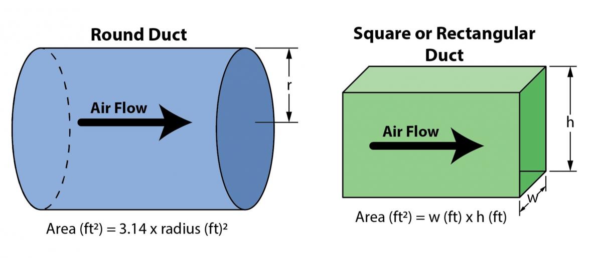
Figure 9. Equations for calculating duct cross-sectional area for round and rectangular ducts; area is used with measured velocity to calculate airflow (Source: FSEC). - Measure the duct cross-sectional air velocity. Since air velocity is not the same across a cross section, several velocity measurements must be made across the area and then averaged together into a single representative value. The measuring/averaging of the velocity measurements for round and rectangular ducts is broken down below:
- First, determine the depths into the duct that the measurements are to be made.
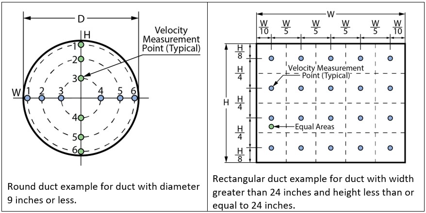
- For the round duct, as seen in Figure 10, the measurement locations are not equally spaced apart. The spacing shown results in velocity measurements at equal areas of duct. Table 2 provides the required spacing for velocity measurements for round ducts of specific diameters. The insertion depth is the same for horizontal plane and vertical plane measurements. Overall, twelve velocity measurements should be made.
| Diameter (in) | Insertion Depth in Inches at Measurement Location # | |||||
|---|---|---|---|---|---|---|
| 1 | 2 | 3 | 4 | 5 | 6 | |
| 3 | 1/8 | 7/16 | 7/8 | 2-1/8 | 2-9/16 | 2-7/8 |
| 4 | 3/16 | 9/16 | 1-3/16 | 2-13/16 | 3-7/16 | 3-13/16 |
| 5 | 3/16 | 3/4 | 1-1/2 | 3-1/2 | 4-1/4 | 4-3/4 |
| 6 | 1/4 | 7/8 | 1-13/16 | 4-1/4 | 5-1/8 | 5-3/4 |
| 7 | 5/16 | 1 | 2-1/16 | 4-15/16 | 6 | 6-11/16 |
| 8 | 3/8 | 1-3/16 | 2-3/8 | 5-5/8 | 6-13/16 | 7-5/8 |
- Average all twelve velocity readings into one representative value (V).
- Determine traverse point locations for rectangular or square ducts. Sixteen total measurement points are suitable for duct dimensions likely to be used for WHMV systems with height and width equal to or less than 24 inches. Table 3 shows the traverse insertion depths for three example sized rectangular ducts. The insertion depth into the duct is shown for four width locations (W1-W4) and four height locations (H1-H4). The next section “Online Calculators” provides guidance for specific duct dimensions different from these examples.
4 x 3 (in) | 6 x 5 (in) | 6 x 8 (in) | |||
|---|---|---|---|---|---|
| W1= 1/2 | H1= 3/8 | W1= 3/4 | H1= 5/8 | W1= 3/4 | H1= 1-0 |
| W2= 1-1/2 | H2= 1-1/8 | W2= 2-1/4 | H2= 1-7/8 | W2= 2-1/4 | H2= 3-0 |
| W3= 2-1/2 | H3= 1-7/8 | W3= 3-3/4 | H3= 3-1/8 | W3= 3-3/4 | H3= 5-0 |
| W4= 3-1/2 | H4= 2-5/8 | W4= 5-1/4 | H4= 4-3/8 | W4= 5-1/4 | H4= 7-0 |
- Calculate WHMV airflow by multiplying the average velocity times the cross-sectional duct area:
Q = V x A
Online Calculators
There are easy-to-use online calculators that will calculate the measurement locations based on duct type and dimensions. The links here are subject to change over time and free access over time cannot be guaranteed. A web search may find others besides the examples here:
Online help calculating measurement locations
Pitot-tube traverse airflow calculator
How to Use a Pitot Tube to Measure Airflow Rate
ANSI/RESNET/ICC Standard 380-2019 does not recognize the pitot tube measurement method. It is however used by trained professionals in commercial buildings for supplemental verification or when performing “test and balance” work on the HVAC system. This method is prone to large error if not done correctly and should only be used by trained professionals.
- Determine the air duct flow profile area (A). This was covered above in the section “How to Calculate Airflow Rate from a Velocity Probe Measurement”.
- Make correct tubing connections between the probe and the manometer to measure velocity pressure. Tubing should be connected so that total pressure is connected to the manometer input and the static pressure is connected to the reference manometer port. The pitot tube photo in Figure 8 shows the total pressure tube on the left with a short piece of blue tubing. The static pressure is the longer tube that turns downward from the total pressure tube. The static pressure tube runs parallel to the inserted probe sensing end and can be used to determine the orientation of the inserted sensing end.
- Choose a smooth straight rigid duct section that is about 8 ½ duct diameters downstream of any duct turns and about 1 ½ duct diameters upstream of turns.
- Determine the twelve locations inside the duct where measurements are to be made (see “How to Calculate Airflow Rate from a Velocity Probe Measurement” above).
- Insert pitot tube into duct so that the inserted tip is pointing into the upstream flow and be sure to keep it oriented parallel to the walls of the duct.
- Average all velocity pressure (Vp) readings into one representative value.
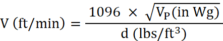
- Convert velocity pressure Vp into velocity (V) (for air at standard air conditions 70°F, 29.92 in Hg barometric pressure) using the following equation:

Note: equations are shown here, but velocity pressure calculators can usually be found online that will quickly convert Vp to V, adjust for air test conditions, and calculate airflow rate with just a few inputs. One example can be found at: (http://www.dwyer-inst.com/flowcalc/) - For non-standard air conditions, first calculate air density (d) using:
d = 1.325 x Pb / T
Where d is density (lbs/ft3) and is determined by measuring absolute air temperature, T, (°F + 460) and the barometric pressure, Pb, (in Hg) - Then calculate air velocity (V) using:
- Finally, calculate WHMV airflow rate (Q) by multiplying the average velocity times the cross-sectional duct area.
Q (cfm) = V (ft/min) x A (ft2)
Ensuring Success
There are different equipment and methods available to measure mechanical ventilation; however, each method has its own strengths and weaknesses, specific to the application, that must be considered in order to make acceptably accurate airflow measurements.
Additionally, in order to ensure a successful and accurate airflow measurement, the contractor, certified rater, or other qualified agent will:
- Refer to ANSI/RESNET/ICC 380-2019 standard for mechanical ventilation flow rate test methods and equipment accuracy.
- Be familiar with other flow measurement techniques not listed in Standard 380-2019.
- Select measurement equipment and methods capable of measuring flowrate within acceptable accuracy.
- When selecting airflow equipment and measurement methods, consider expected weather conditions and locations where measurements are to be made (i.e., indoors/outdoors, inlet/outlet terminal, or in-line).
- When flow must be measured at outdoor grilles, be aware of air velocity impacts from other equipment like outdoor heat pump units. Make sure any such equipment that is very near to the outdoor grille being accessed is turned off during WHMV airflow measurements.
Region
No climate-specific information applies.
Training
Right and Wrong Images
Source
Report describing the results of a 21-home field study investigating the effectiveness and failure rates of whole-house mechanical ventilation systems installed in Florida homes over the last 15 years.
Compliance
Retrofit
Guidance for the measures described in this guide is applicable to both new and existing homes.
For more information about specific mechanical ventilation airflow measurement methods and types of equipment needed, see ANSI/RESNET/ICC 380-2019 Standard for Testing Airtightness of Building, Dwelling Unit, and Sleeping Unit Enclosures; Airtightness of Heating and Cooling Air Distribution Systems; and Airflow of Mechanical Ventilation Systems
For more information on assessing existing ventilation systems, see the Solution Center information guide Pre-Retrofit Assessment of Ventilation Systems
See the Solution Center guide Whole House Ventilation Strategies for Existing Homes for an extensive discussion on the topic.
More Info
References and Resources
*For non-dated media, such as websites, the date listed is the date accessed.
Contributors to this Guide
The following authors and organizations contributed to the content in this Guide.
Questions? Comments? Contact our webmaster.