

Scope
Install lateral bracing in gable end walls to ensure the building will resist design wind pressures. This guide provides an overview of lateral bracing in gable end walls with a focus on applications in hurricane-prone regions or other high-wind areas.
- If the house is in a hurricane-prone region or other high-wind area, strengthen the gable end wall connection to the wall below, in accord with the requirements of the IBHS Fortified Home Hurricane and High-Wind Standards.
- Install 7/16 in.-structural sheathing (OSB or plywood) on the vertical face of the gable end wall.
- Brace gable end walls taller than 48. inches in height to resist wind forces by installing a framing assembly at each gable wall stud. The framing assembly incudes horizontal braces, vertical retrofit studs, and compression blocks.
See the Compliance tab for links to related codes and standards and voluntary federal energy-efficiency program requirements.
Description
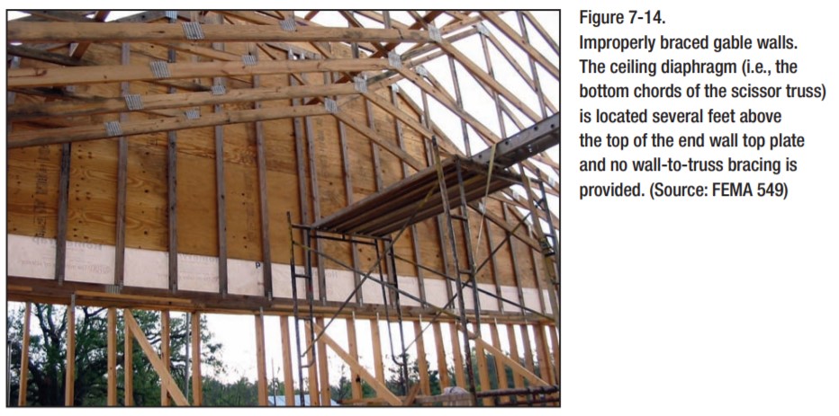
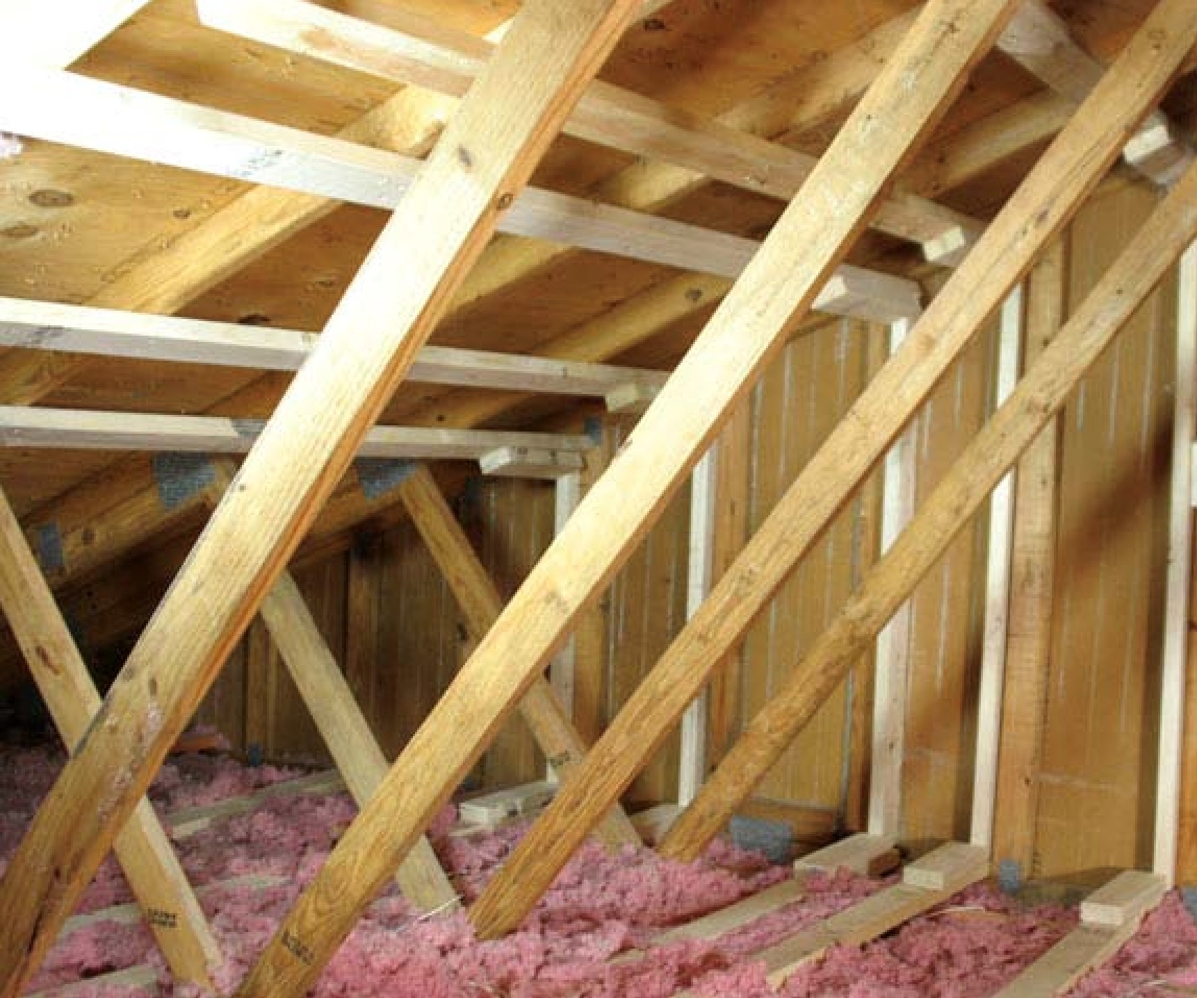
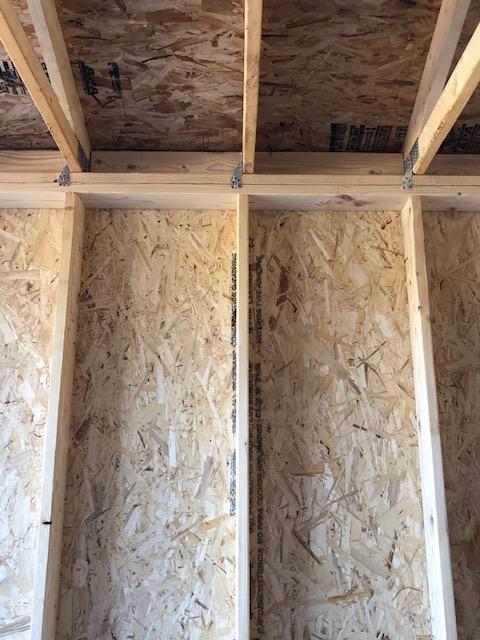
Gable end walls are the triangular sections of wall that extend above the top plate at the gable ends of houses with gable roofs. Gable end walls that are inadequately braced or improperly anchored are vulnerable to collapse during high winds.
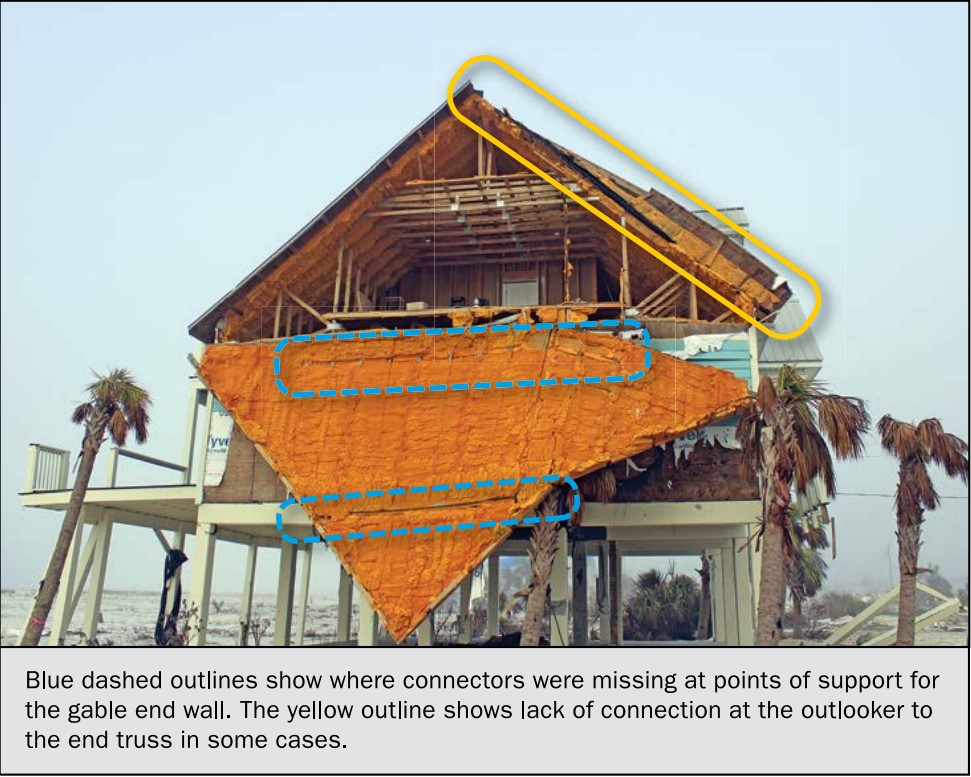
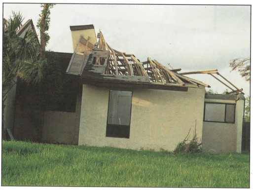
During a hurricane, tornado, or high winds, gable end walls can be damaged or detached from the rest of the structure, leading to severe damage to the roof and other structural members of the house (Figures 1 and 2). A compromised gable end wall can allow rainwater to enter the building causing severe damage, including saturation of insulation and ceiling drywall, potentially leading to collapsed ceilings and extensive damage to the interior of the home and its contents.
Wind forces both push (inward acting) and pull (outward acting) on houses, so it is critical to brace the gable ends to resist wind pressures in both directions. The potential critical failure points are the gable end wall connections at the roof framing and sheathing above and the wall below, gable wall framing members, and gable wall sheathing.
The International Residential Code (IRC 2018) requires exterior building components and their attachments to be capable of resisting design wind pressures. For some high-wind regions, the IRC requires wind design in accordance with other methods including the International Building Code (IBC 2018).
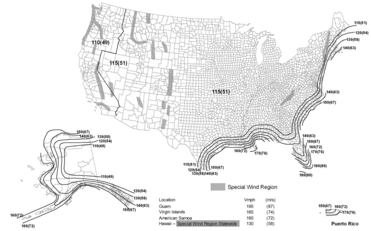
Homes located in coastal high-wind areas including Hurricane-Prone Regions generally require enhanced attachment that can withstand greater wind speeds than the rest of the country. The IRC defines Hurricane-Prone Regions as areas along the Atlantic and Gulf Coasts where wind velocity is >115 mph, and Hawaii, Puerto Rico, Guam, the Virgin Islands, and American Samoa (see the IRC wind map in the Climate tab). Confirm with the local building department if the house is in a hurricane-prone region and if local requirements exceed those of the IRC.
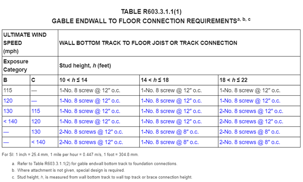
The IRC does not specify requirements for bracing gable end walls for wood framing but has minimum requirements for continuous roof sheathing at gable end walls, including fastener (nail) type, spacing, and penetration depth into structural members (see the Compliance tab for details). Section R603.3.1.1 of the 2018 IRC specifies gable end walls with heights greater than 10 feet (3,048 mm) are to be anchored to foundations or floors in accordance with IRC Table R603.3.1(1) or R602.3.3.1.1(2). IRC Section R603.3.2.1 specifies stud size and thickness for the gable end walls.
The Insurance Institute for Business and Home Safety® (IBHS) offers guidance, best practices, and voluntary construction standards and programs for building in disaster-prone areas including hurricane and high-wind zones. The IBHS FORTIFIED HOME™ standard is designed to make homes more resilient and durable; guidance is available for New Construction and Existing Homes in Hurricane zones and High-Wind zones There are three levels of FORTIFIED Home: FORTIFIED Roof™ focuses on the roof; FORTIFIED Silver focuses on roof overhangs, opening protection, gable ends, and attached structures; FORTIFIED Gold focuses on tying all of the components of the structure together.
The IBHS FORTIFIED Home Hurricane Standard requires gable walls subjected to high winds to have structural sheathing attached to the vertical face consisting of 7/16-in. OSB or plywood. The IBHS FORTIFIED Home High Wind Standard requires gable end walls to have a structural wall sheathing that is a minimum of 3/8-inch plywood or OSB or equivalent.
How to Install Lateral Bracing in Gable End Walls
- Strengthen the gable end wall, as required:
- Minimum 3/8-inch thick structural wall sheathing over the entire gable end wall
- Maximum 24-inch spacing between studs on gable end walls.
- Strengthen the gable end wall connection to the wall below using metal bracket connectors and one of the following methods:
- Attach the bottom chord of the gable end wall to the wall below using right angle gusset brackets consisting of 14-gauge or thicker material with a minimum load capacity of 350 pounds. Install the right-angle gusset brackets along the wall where the gable end wall height is greater than 3 feet at the spacing specified in the table below. Use a minimum of two fasteners specified by the manufacturer to attach the angle gusset bracket.
- For a conventionally framed gable end wall, attach each stud along the wall where the height of the wall is greater than 3 feet to the bottom plate using a stud-to-plate connector. Connect the bottom plate to the wall below using 4.5-inch, ¼-inch-diameter screws.
| Exposure Category | Wind Speed, mph Maximum 3-Sec. Gust | Maximum Spacing of Right Angle Gusset Brackets |
|---|---|---|
| C | 110 | 38 in. |
| C | 120 | 32 in. |
| C | 130 | 28 in. |
| C | 140 | 24 in. |
| C | 150 | 20 in. |
| B | 110 | 48 in. |
| B | 120 | 40 in. |
| B | 130 | 36 in. |
| B | 140 | 30 in. |
| B | 150 | 26 in. |
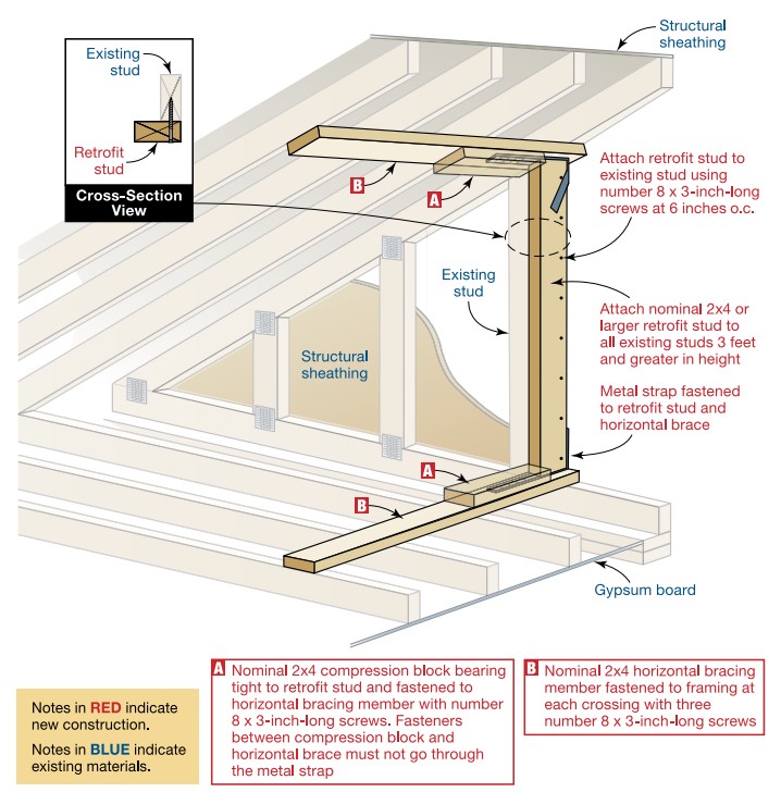
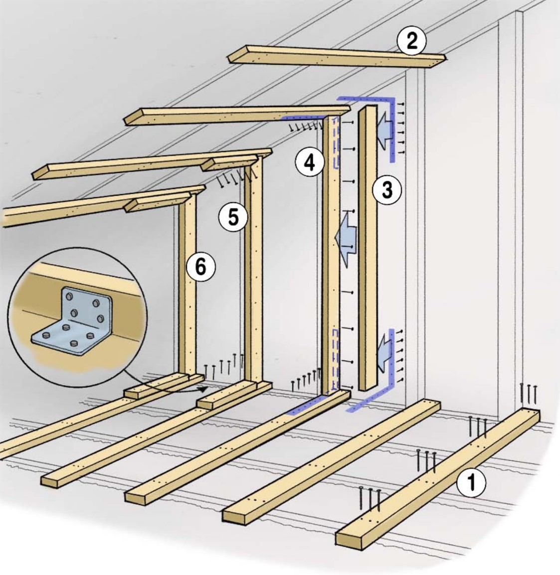
For steps 3 through 5, refer to Figure 3.
3. Install horizontal bracing, perpendicular to the gable wall, at the bottom chord or ceiling joist, and at the top chord or roof rafter, at each gable end wall stud greater than 3 feet high. Attach bracing using three #8 x 3-in. screws at each truss chord or rafter and joist.
4. Attach a vertical retrofit stud, between the upper and lower horizontal bracing, to each existing gable wall stud.
- Attach a retrofit stud to the upper and lower horizontal bracing using metal straps, minimum 20-gauge x 1-1/4-in. wide with pre-punched fastener holes, using #8 screws.
- Attach retrofit stud to existing stud using #8 x 3-in. screws at 6 inches on-center
- The maximum allowable gap between the retrofit stud and bracing is 1/8-in. at the lower brace and 1/2-in. at the upper brace.
5. Install compression blocks on horizontal bracing bearing tightly against the vertical retrofit stud, to restrain horizontal movement. Attach compression blocks using three #8 x 3-in. screws; screws must not go through the strapping.

Ensuring Success
Dimensional lumber used for braces, studs, and blocking should conform to applicable standards or grading rules. Metal plate connectors, straps, and anchors should have product approval and should be approved for connecting wood to wood. Straps and tie plates should be manufactured from galvanized steel with a minimum thickness provided by 20 gauge and have holes sized for 8d nails.
See if local building codes have specific requirements or ask the local building department. For disaster resistance, comply with the roofing requirements defined by the IBHS Fortified Home Program.
Region
The International Residential Code does not have specific requirements for gable end wall bracing but general requirements for wood wall framing are provided in Section R602.
Homes located in coastal high-wind areas including Hurricane-Prone Regions generally require enhanced attachment that can withstand greater wind speeds than the rest of the country. The IRC defines Hurricane-Prone Regions as areas along the Atlantic and Gulf Coasts where wind velocity is >115 mph, and Hawaii, Puerto Rico, Guam, the Virgin Islands, and American Samoa.
The Insurance Institute for Business and Home Safety® (IBHS) offers guidance, best practices, and voluntary construction standards and programs for building in disaster-prone areas including hurricane and other high-wind zones. The IBHS FORTIFIED Roof™ program includes guidance on sealed roof decks, flashing, and shingle attachment.
Training
Right and Wrong Images
Source
Guide discussing observations, recommendations, and technical guidance as a result of Hurricane Katrina

Source
Guide describing the requirements by FORTIFIED Home™ for improving the home's resistance in severe thunderstorms, straight-line wind events, and high winds at the outer edges of tornadoes.

Source
Report containing 37 fact sheets that provide technical guidance and recommendations concerning the construction of coastal residential buildings.
Source
Report providing guidance on how to improve the wind resistance of existing residential buildings in Mississippi and across the Gulf Coast.
Source
Report providing guidance on how to improve the wind resistance of existing residential buildings in Mississippi and across the Gulf Coast.
Source
A builder's guide describing hurricane-resistant reinforcements for gable ends.
Source
A builder's guide describing hurricane-resistant reinforcements for gable ends.
Source
Videos

Retrofit
The FEMA Wind Retrofit Guide for Residential Buildings (FEMA P- 804) has information for retrofitting existing gable end walls in residential buildings.
Step 1: Check the stud spacing and wall connections for the existing gable end walls.
- Conventionally framed gable end walls can be strengthened by using straps or right-angle brackets to anchor each stud longer than 3 feet to the upper and lower framing members (frequently existing studs are only toe-nailed).
Step 2: Vertical framing members can be strengthened by installing retrofit studs that are adjacent to the gable end wall stud and extend from the top of the lower horizontal brace to the bottom of the upper horizontal brace.
- The retrofit stud is a nominal 2-inch lumber member used to structurally supplement an existing gable end wall. A maximum gap of 1/8 inch is permitted between the retrofit stud and the bottom horizontal brace and ½ inch is permitted between the top edge of the retrofit stud and the horizontal brace.
- Fasten each retrofit stud to the top and bottom horizontal brace members with a minimum of a 20-gauge, 1 ¼ inch wide flat metal strap with pre-punched fastener holes. The strap should be fastened using #8 wood screws or 8d nails. They should also be fastened to the side of the vertical gable end wall studs with #8 wood screws or 10d nails spaced at 6 inches o.c.
Step 3: Follow the steps in the Description Tab to install lateral bracing as required.
Step 4: Ensure the sheathing thickness is at least 3/8 inch and re-nail sheathing if required.
More Info
References and Resources
*For non-dated media, such as websites, the date listed is the date accessed.
Contributors to this Guide
The following authors and organizations contributed to the content in this Guide.
Questions? Comments? Contact our webmaster.