

Scope
Install continuous top plates or blocking at the tops of walls adjacent to unconditioned space to minimize air leakage.
- Design walls with top plates. Do not specify balloon framing.
- Install a continuous top plate at all full height walls.
- Where walls of varying heights meet, install blocking if needed in any wall cavities that are open to an unconditioned attic or other unconditioned space. Use rigid blocking material such as lumber, plywood, OSB, or rigid foam, caulked or sealed at edges.
See the Compliance Tab for links to related codes and standards and voluntary federal energy-efficiency program requirements.
Description
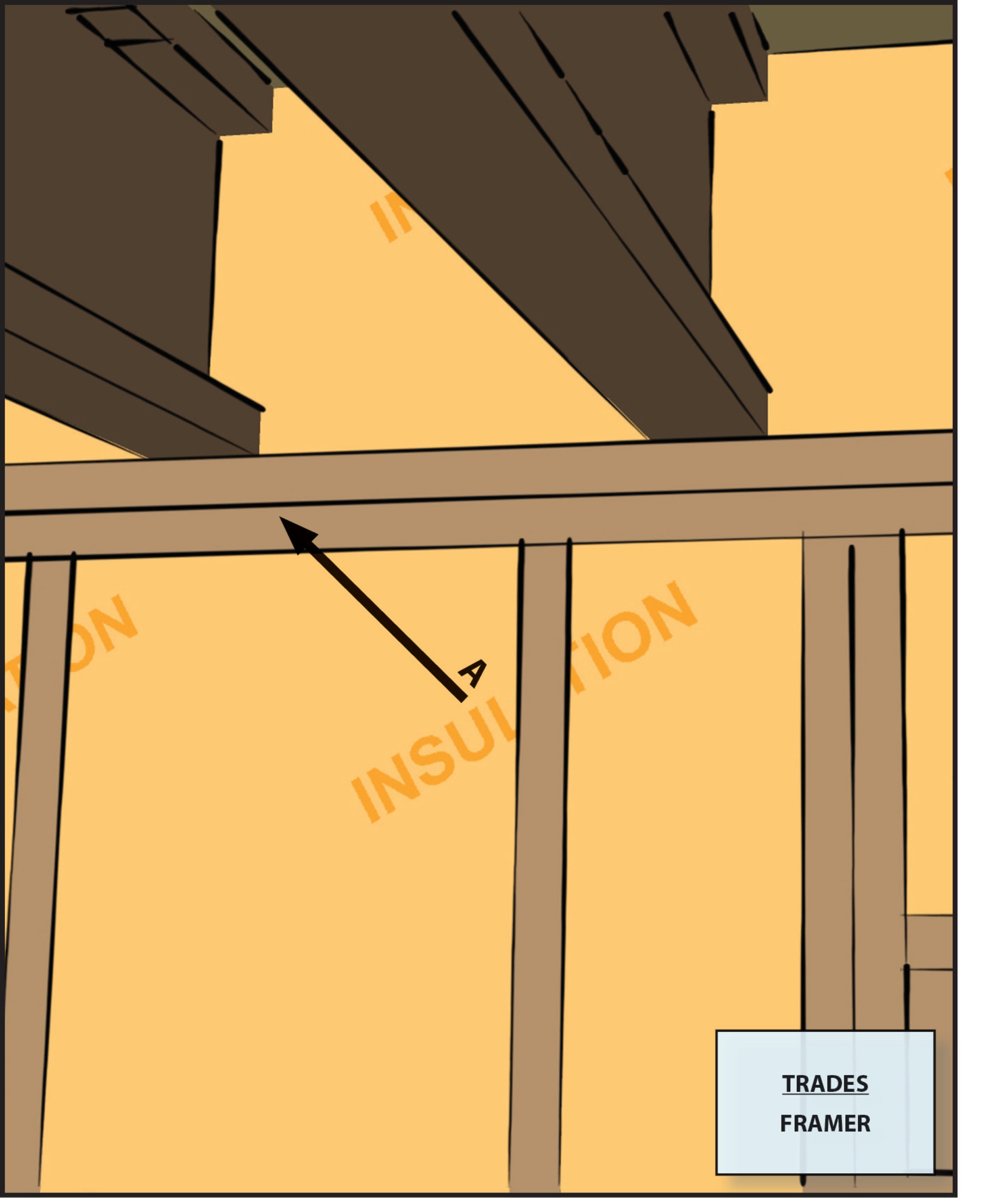
Most wall cavities are composed of a horizontal top plate, a horizontal bottom plate, and the vertical studs. When gypsum board and wall sheathing are caulked and fastened to the inside and exterior faces of these components, they create an air-tight six-sided wall cavity. If one element is missing from this assembly or is not adequately air sealed to the other elements, air will flow through the cavity, potentially robbing any insulation present of its insulating value. Some wall designs have no top plate so the wall cavity is open to the area above, which may be an unconditioned attic or other unconditioned space. This opening can become a pathway allowing unconditioned air from the attic to flow down into the wall cavity and conditioned air from the wall to flow up into the attic. The result is unwanted heat loss or heat gain, cold spots in walls, and an increased potential for moisture problems in the wall or attic.
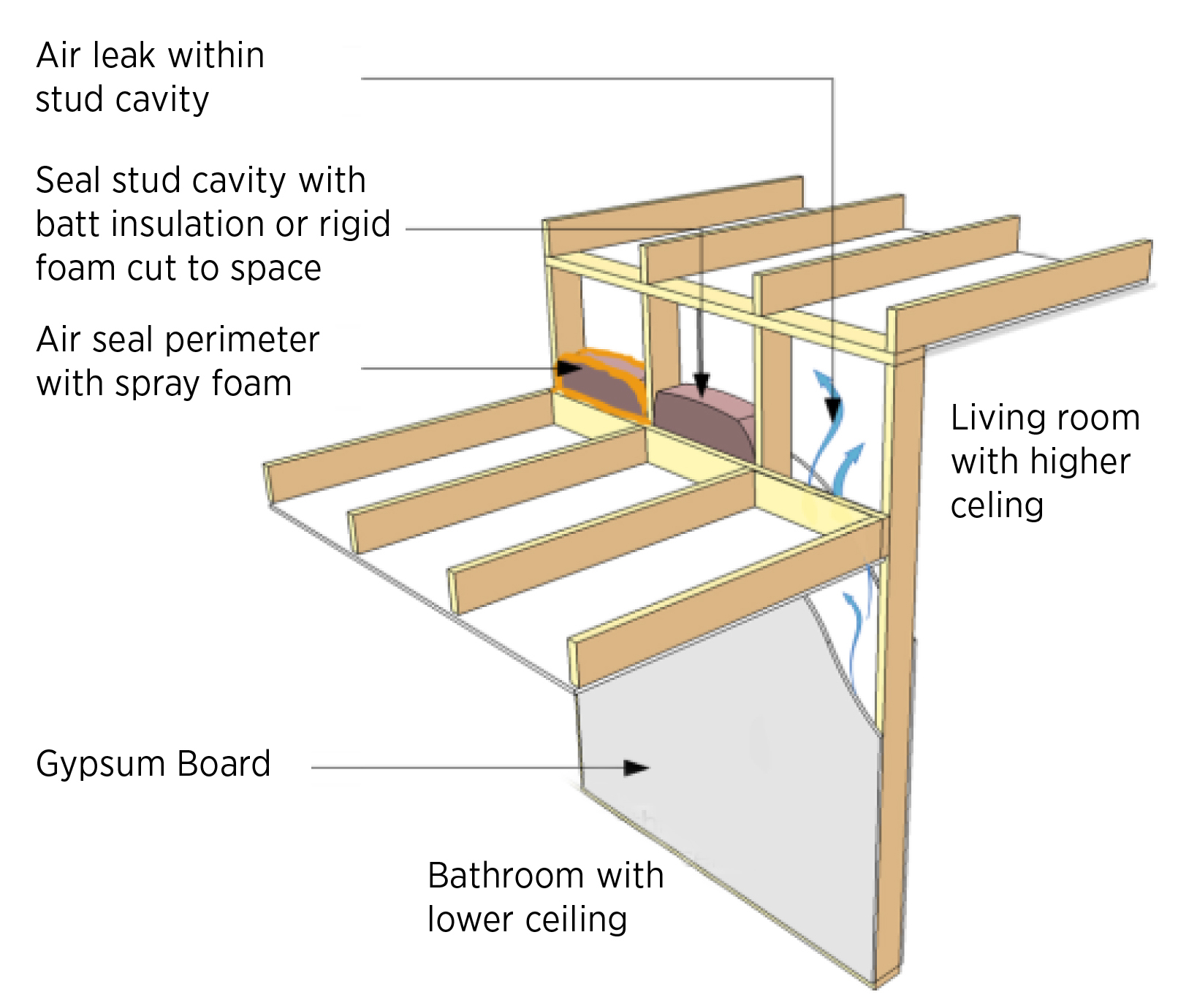
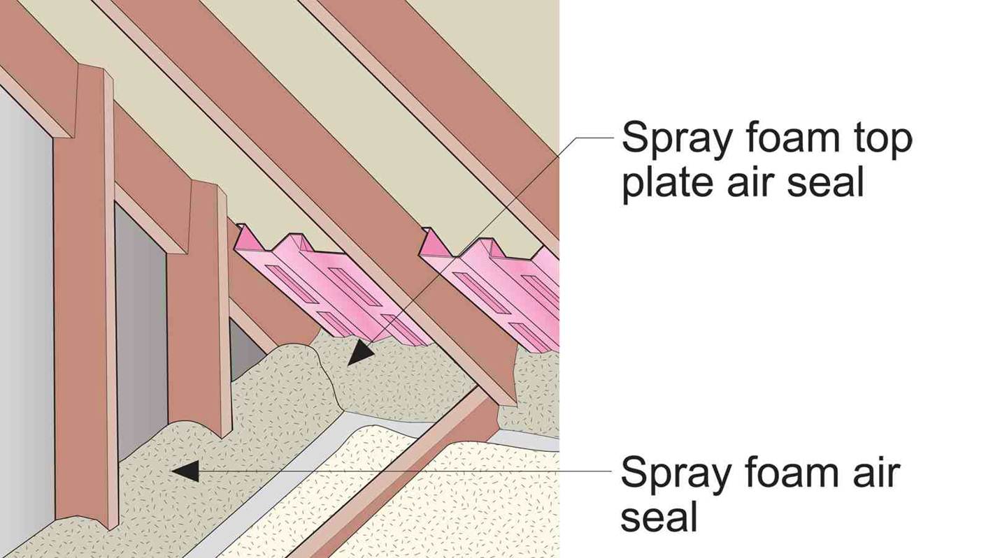
Missing top plates can sometimes occur when a room of one ceiling height abuts a room of a taller ceiling height. They can also occur when buildings are designed with balloon framing. Designers should not specify balloon framing. If the house design includes varying ceiling heights, blocking should be specified where the top of the lower wall meets the side of the higher wall if no top plate is present. This blocking material could be rigid foam, plywood, OSB, or lumber that is cut to fit. Alternately, the open stud cavities can be filled with fiberglass batting that is rolled and tucked into the cavity opening then covered with spray foam.
How to Air Seal a Wall with a Missing Top Plate
- Identify missing top plates in adjoining walls with different ceiling heights.
- Select a rigid air-blocking material (rigid foam insulation, plywood, OSB, lumber). Cut into pieces to fit each stud bay. Wrap a thin piece of strapping around the board to hold it in position while you nail each piece in place, then seal edges with caulk or fire-blocking spray foam. Pull the strap out and glue the remaining two sides.
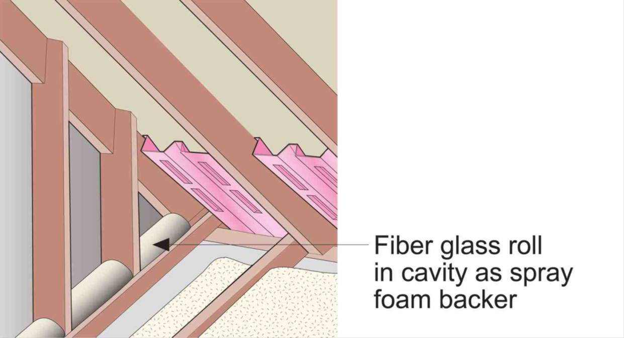
- Or, roll a piece of unfaced fiberglass batt insulation for each cavity. Pressure fit the fiberglass batt roll into the top of the stud cavity. Cover the top with fire-blocking spray foam to air seal the roll and hold it in place.
How to Air Seal Open Wall Cavities in Balloon-Framed Walls
- Identify open wall cavities in balloon-framed walls. Note, balloon-framed walls are walls that have no top plates so wall cavities are open from the bottom plate to the attic. This style of construction is not recommended.
- Roll a piece of fiberglass batt and stuff it into place at the top of the wall where the top plate is missing.
- Cover the roll of fiberglass batt with fire-stopping spray foam to air seal it in place.
- Fill the attic with additional insulation.

Ensuring Success
Design homes so that all full-height walls have a continuous top plate. If the house plan has some area where a top plate cannot practically be included in the framing design, such as where a room with a lower ceiling height abuts a room with a higher ceiling height, indicate on the plans that air-blocking material should be installed, then inspect that it is properly installed and sealed in place with caulk or spray foam.
Region
Colder climates will increase the potential for heat loss and air leakage, and the impacts of that heat loss, if the top plates are not properly insulated and air sealed. Heat loss into the attic can warm the underside of the roof deck which can contribute to snow melt and ice dam formation. Significant air leakage from the house into the attic increases the potential for condensation and frost formation in the attic, if warmer vapor-laden conditioned air is allowed to escape into a wintertime attic with cold surfaces.
Training
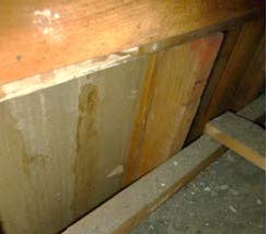
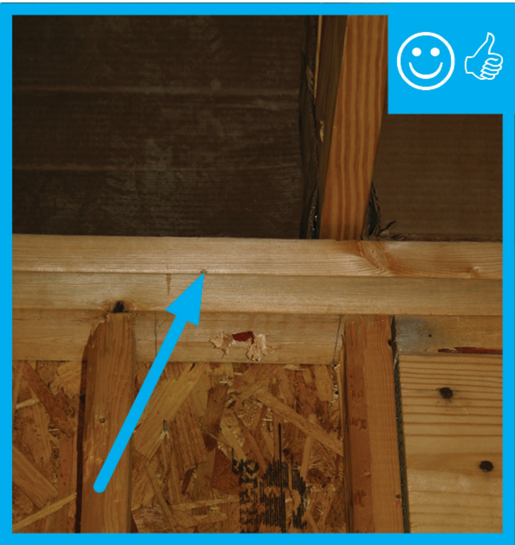
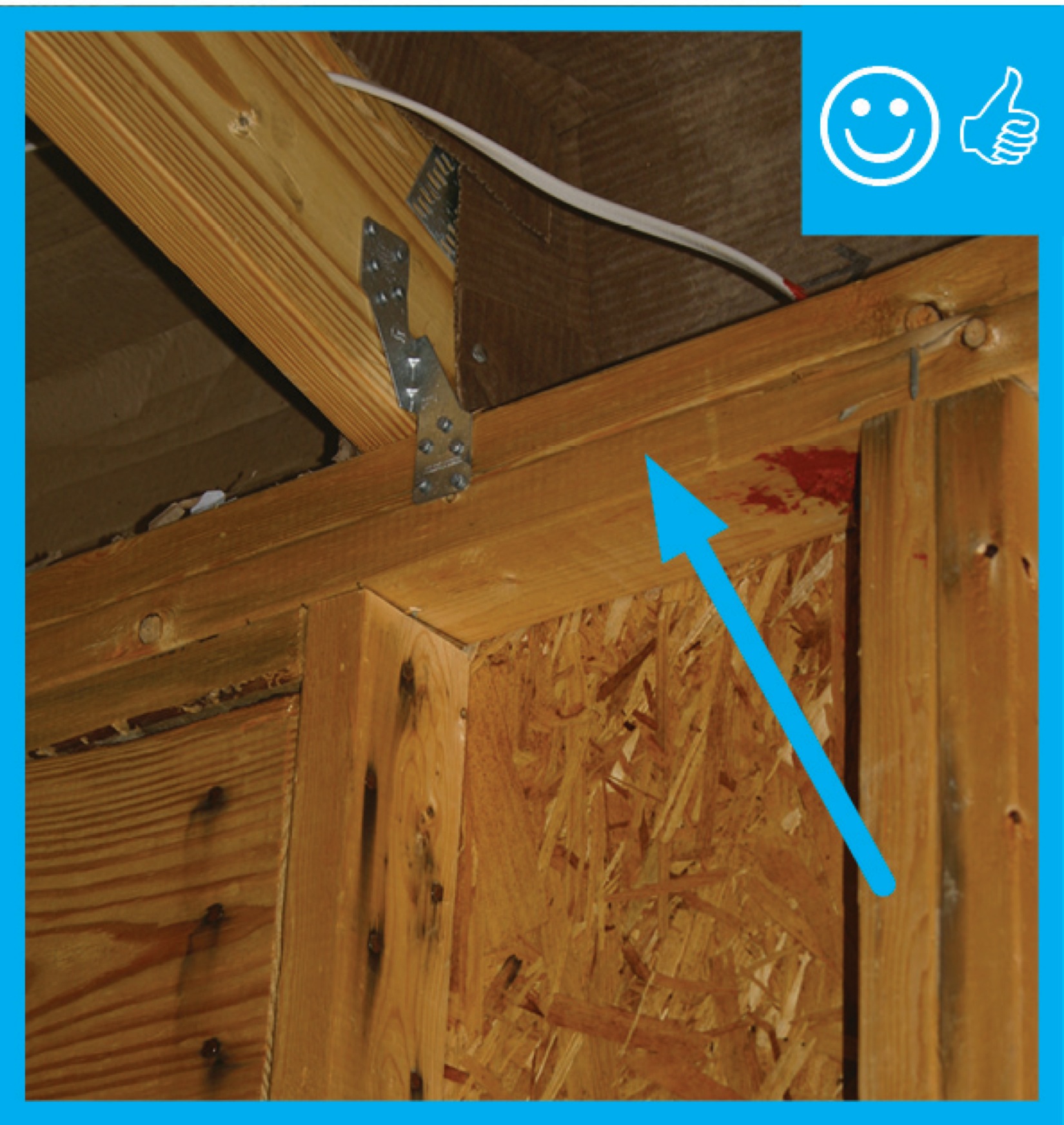
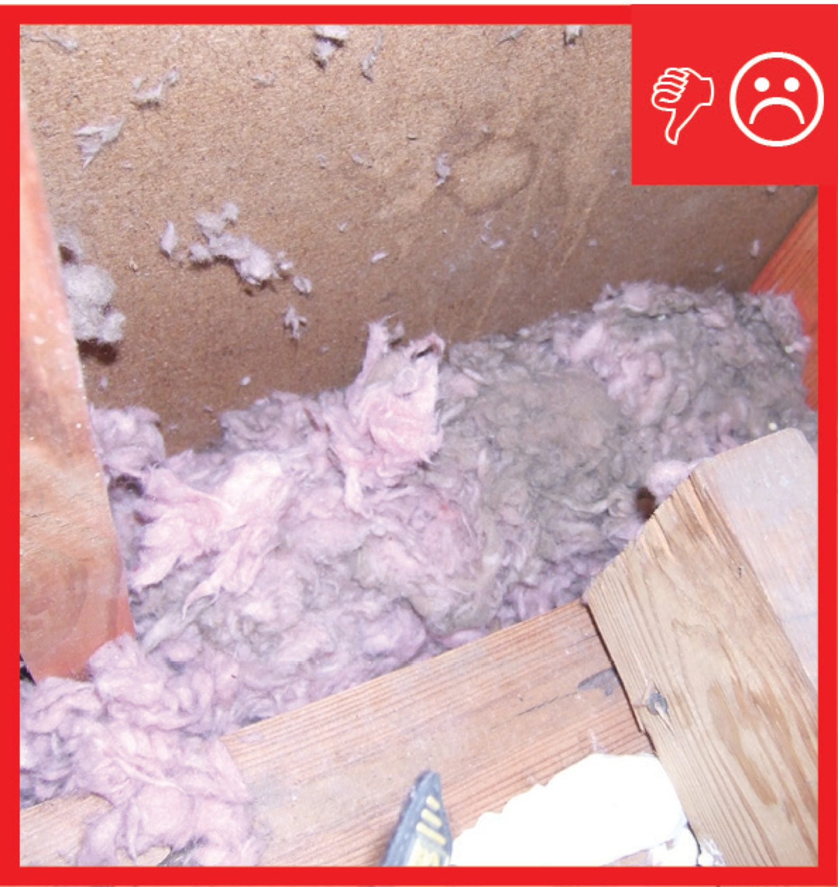
Right and Wrong Images
Source
Guide describing details that serve as a visual reference for each of the line items in the Thermal Enclosure System Rater Checklist.
Source
Guide describing details that serve as a visual reference for each of the line items in the Thermal Enclosure System Rater Checklist.
Source
Guide describing details that serve as a visual reference for each of the line items in the Thermal Enclosure System Rater Checklist.

Source
Guide describing details that serve as a visual reference for each of the line items in the Thermal Enclosure System Rater Checklist.
Source
Guide describing details that serve as a visual reference for each of the line items in the Thermal Enclosure System Rater Checklist.
CAD Files


Compliance
Retrofit
SCOPE
See the techniques described in the Description tab of this guide, which apply well to existing homes.
- Use precautions when accessing attics, as described below.
- If this work is part of an effort to insulate an attic, consider this and other attic air-sealing measures before installing the insulation.
The U.S. Department of Energy’s Standard Work Specifications (SWS) define minimum requirements to ensure that the work performed during home energy upgrades is effective, durable, and safe. The Standard Work Specifications include specifications for the following topics, which may be applicable to air sealing walls at missing top plates.
- global worker safety.
- worker health and safety specifications related to air sealing.
- general air sealing of attics.
- insulating attic ceilings.
- soffit ventilation and baffles.
- combustion safety, which may be impacted by air sealing.
DESCRIPTION
The techniques described for air sealing at missing top plates in the new home tabs for this guide apply well to existing homes.
It may be difficult to access the top plates or the areas where top plates should be. These attic areas may be most accessible when other projects are underway, such as when roofing is being installed, when insulation is being installed (reroofing is also a good time to add insulation), or when a wall is being repaired.
Some attic areas, such as over porches or in isolated sections of the attic, may not have access panels or doors. If comfort or energy bills are being impacted, then adding an access panel may be justified; however, steps must be taken to control dust when cutting through existing walls or ceilings in homes built before 1978, which may contain lead paint. Old plaster may contain asbestos. See the assessment guide on hazardous materials and the EPA Healthy Indoor Environment Protocols for Home Energy Upgrades (2014) for more information.


To minimize crumbling of plaster when cutting through existing plaster and wood lathe surfaces, use high-speed cutting tools such as powered multi-tools or an angle grinder with a diamond blade, to make clean cuts through the plaster and lathe. Protect surfaces, hang tarps to isolate the area, and operate a shop vac to capture the dust. Another trick is to apply a sealing compound to the back side of the lathe, if it is accessible, prior to cutting to minimize flexing. Apply masking tape to the lines to be cut to help hold the plaster together. Wetting may also help reduce dust generation.
If this work is being undertaken as part of a project to insulate the attic, consider other attic air-sealing activities before insulation is installed. (See the Attic Air Sealing Guide and Details). Air sealing should be done before insulation is installed. Once in the attic space, look for duct work that needs air sealing and insulation. (There are many guides on this topic in the Solution Center).
To avoid durability issues and hazardous conditions, use the pre-retrofit assessment guides for attics and walls.
The approaches used for air sealing may depend on whether the unconditioned space will be ventilated or treated as a conditioned space. See the guides on insulating existing attics or roofs in the Existing Homes tool.
Air sealing may impact the amount of air available for combustion appliances. If combustion appliances are present in the home, before starting the air sealing, see the Pre-Retrofit Assessment of Combustion Appliances guide for ways to ensure that there is adequate fresh air for combustion appliances. In ventilated attics, ensure there is adequate ventilation as described in the guide on Calculating Attic Passive Ventilation.
COMPLIANCE
See Compliance tab.
More Info
References and Resources
*For non-dated media, such as websites, the date listed is the date accessed.
Contributors to this Guide
The following authors and organizations contributed to the content in this Guide.
Steven Winter Associates, lead for the Consortium for Advanced Residential Buildings (CARB), a DOE Building America Research Team
Building Science Corporation, lead for the Building Science Consortium (BSC), a DOE Building America Research Team
Sales
Tight Air Sealed Home = Comprehensive Draft Protection
Technical Description
Poorly air-sealed homes are less comfortable and cost more to maintain because they provide a pathway for drafts, cold spots, moisture, and insects into the home. Comprehensive draft protection includes a continuous air barrier around the whole house along with caulking and sealing in all holes and cracks. This includes around wiring, plumbing, ducts, and flues; where wall framing meets flooring; around windows; where drywall meets top plates and sill plates; where rim joists meet foundation walls and subfloors; etc. Spray foam insulation can be used at rim joists, floors above unconditioned space, and in attics to insulate and air seal at the same time.
Questions? Comments? Contact our webmaster.