

Scope

Integrate high-thermal-mass construction, along with passive heating and cooling strategies, to reduce heating and cooling energy consumption and to help regulate the indoor temperature of the home during extreme heat conditions, cold snaps, and power outages.
- Determine your IECC Climate Zone.
- Determine if high-thermal-mass construction would be beneficial in your climate, considering length of cooling season, length of heating season, and typical daytime-nighttime (diurnal) temperature swings during the cooling season.
- Select high-thermal-mass construction materials like concrete masonry units (CMU), poured concrete, insulated concrete forms (ICF), stone, brick, or other masonry materials for interior and exterior wall construction.
- Select a high-thermal-mass construction material for floors like concrete slab or tile.
- Consider incorporating phase change materials (PCMs).
- Provide external insulation to minimize external heat absorption by the thermal mass walls and maximize the lag and damping effect of thermal mass.
- Minimize thermal bridging at joints and projections.
- Integrate passive heating and cooling techniques to take advantage of the building-integrated thermal mass.
See the Compliance Tab for links to related codes and standards and voluntary federal energy-efficiency program requirements.
Description
Building construction, design, and operation strategies can be employed to conserve heating and cooling energy and to improve the resiliency of buildings and safety of occupants during extreme heat events, winter weather, and power outages. One such strategy is to use building-integrated thermal mass, or high-thermal-mass construction, for temperature regulation as part of passive heating and cooling strategies. See the Passive and Low-Energy Cooling guide for more information on passive strategies.
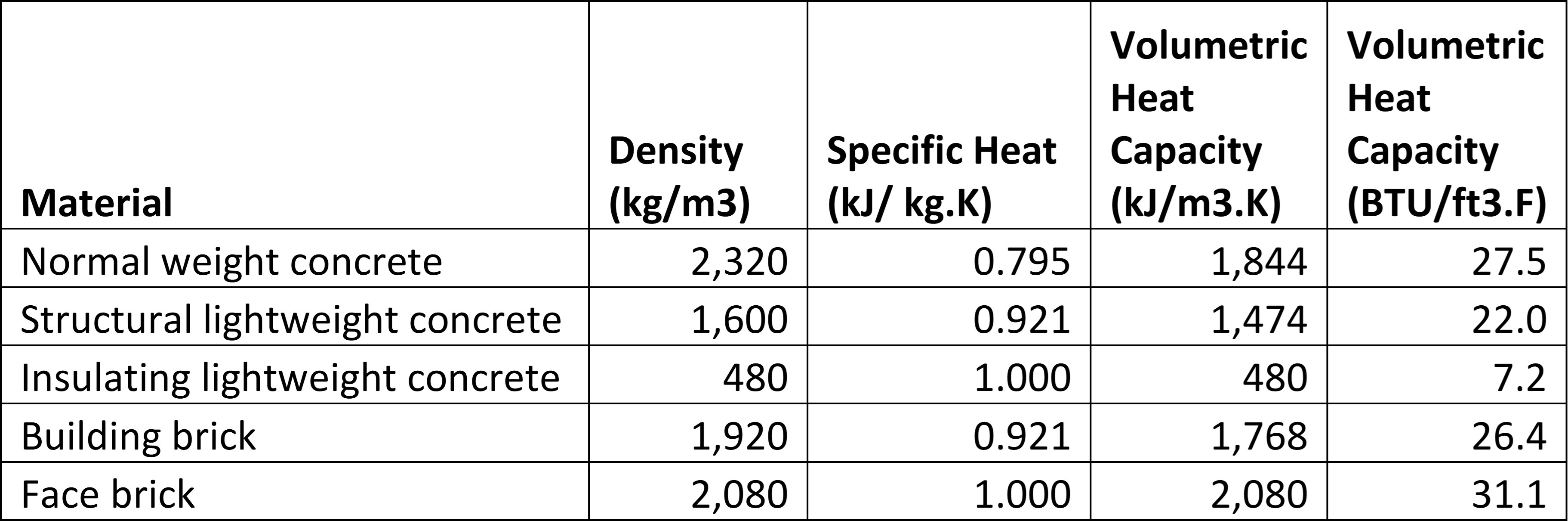
Thermal mass, also known as heat capacity, is the ability of a material to store heat – the higher the thermal mass of the material, the higher its ability to store heat. Some examples of construction materials with higher thermal mass are listed in Table 1. Masonry materials tend to have high thermal mass as shown in this table which lists the density, specific heat, and volumetric heat capacity (in metric and in English units) of various construction materials.
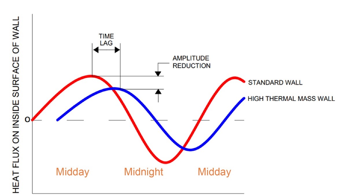
Thermal mass construction can stabilize internal temperatures by creating a heat sink that provides a time-lag in the transfer of heat between inside and outside and a damping effect to indoor temperature swings. While the outdoor temperature peaks at midday, the interior temperature in a home with high-thermal-mass walls will peak a few hours later (time lag). Further, the temperature increase will be less overall (thermal damping) (Habian 2015). Figure 1 illustrates the time lag and thermal dampening (called amplitude reduction in the figure) of heat transfer through a high-thermal-mass wall as compared to a standard wall. The thermal damping effect is greater in locations that experience a larger daytime-nighttime temperature difference. During periods of extreme heat or cold and loss of electrical power, thermal mass construction can help to provide indoor comfort for longer durations compared to standard construction (Staszczuk and Kuczynski 2021).
For thermal mass to be effective in dampening interior temperatures, it should be distributed over a large area throughout the house. Entire floors and walls work well, while individual columns or more compact masonry features are less effective. In order to contribute meaningfully to a passive heating or cooling strategy, the large area of thermal mass must also be exposed to the indoor air. A concrete wall that is insulated on the inside will not aid a passive solar heating or a night flush cooling strategy. Insulated concrete forms (ICF) and CMU block walls with rigid foam on the inside are two examples of wall types that are insulated on the inside. Thus, their ability to dampen indoor temperature swings is greatly reduced.
Thermal mass that is not exposed to the indoor air still has value, however. Extreme outside temperatures are moderated as heat travels through the thermal mass of the wall, so heat gains and losses through the wall are evened out over time.
While building-integrated thermal mass can contribute to passive cooling strategies and combat the effects of extreme heat, it has to be coupled with correct design considerations to be effective. For example, poor window placement could increase solar heat gain in summer, warming the indoor concrete slab with direct sunlight during the day, resulting in storing more heat during the day and releasing it during the night, thus increasing the nighttime indoor temperature (Reardon 2013).
Building with high-thermal-mass materials has pros and cons. Concrete walls are bulky, reducing interior space and require curing time. Building with concrete can contribute to a tighter building envelope, which is good for energy efficiency and occupant comfort, but can contribute to high indoor humidity early on as the concrete cures. Compared to wood-framed walls, masonry walls may cost more, be more difficult to renovate in the future, have a higher carbon footprint, and be less seismically resilient if not properly reinforced. However, masonry walls are more resistant to termites, hurricanes, and fire.
High thermal mass materials like stone and rammed earth have been used to construct homes throughout history but more common materials in the present time are blocks made of concrete that are more energy and labor efficient.
When combined with passive heating and cooling strategies like building orientation, insulation, appropriate glazing, shading, and reflective surface materials, high-mass construction can help to regulate indoor temperatures during extreme heat, extreme cold, and power outages. Descriptions of several high-mass construction methods, including Trombe walls which are primarily used for passive heating, are provided below.
High-Thermal-Mass Construction Materials
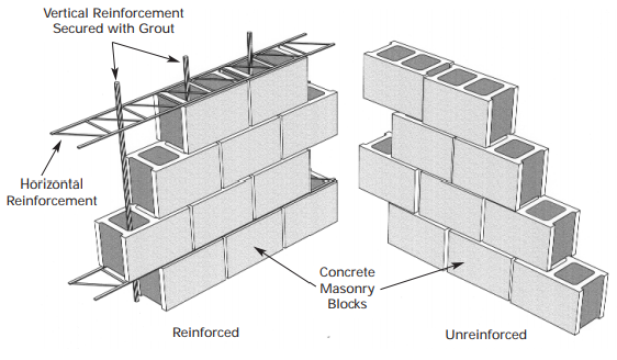
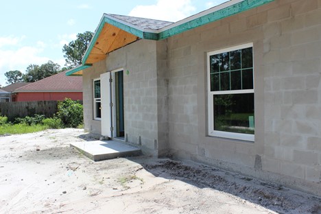
Concrete Masonry Unit (CMU) Construction uses hollow-core concrete blocks that are stacked in an offset pattern like bricks. CMU walls can be reinforced as required with horizontal steel mesh between courses, or vertical steel rebar through the hollow core which is then normally filled with concrete (Figures 2 and 3). The CMUs can be lightweight, normal-weight, or heavy-weight. Normal-weight and heavy-weight units are used for load-bearing walls and lightweight units are used for non-load bearing walls. The CMUs can be manufactured to different dimensions but typically have a face height of 8 inches and a width of 16 inches.
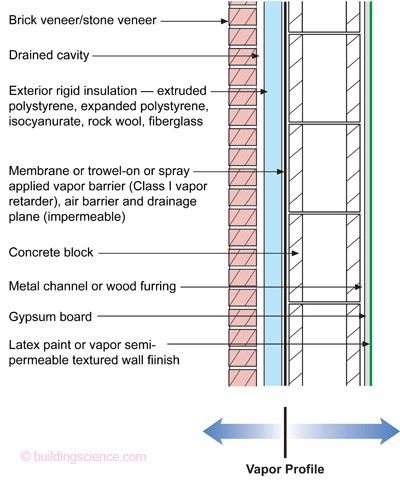
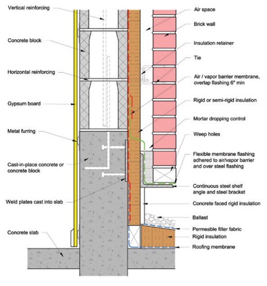
CMU walls require insulation, which can be installed on the interior or exterior. Insulation should be placed on the exterior to take advantage of the thermal mass properties of CMU walls (see Figure 4). In areas where termite activity is a concern, careful detailing of termite barriers is necessary to prevent the underside of the insulation from becoming an easy path for termites to reach wood-framed structure above. CMU cavities, where not already filled with concrete, can be filled with insulation to reduce heat transfer or with concrete to increase thermal mass.
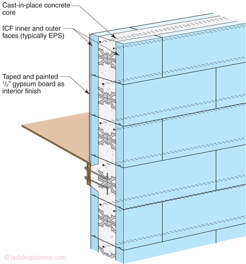
Insulated Concrete Form (ICF) Construction uses insulated “blocks,” which serve as forms for poured concrete. The insulated blocks remain in place after the concrete is poured. The ICF block consists of two layers of expanded polystyrene (EPS) rigid insulation separated by integral plastic or metal spacers. The spacers maintain the gap between the inner and outer insulation panels and are also integrated with tabs that provide attachment points for interior drywall and exterior cladding. See Figures 5 and 6.
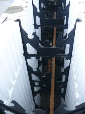
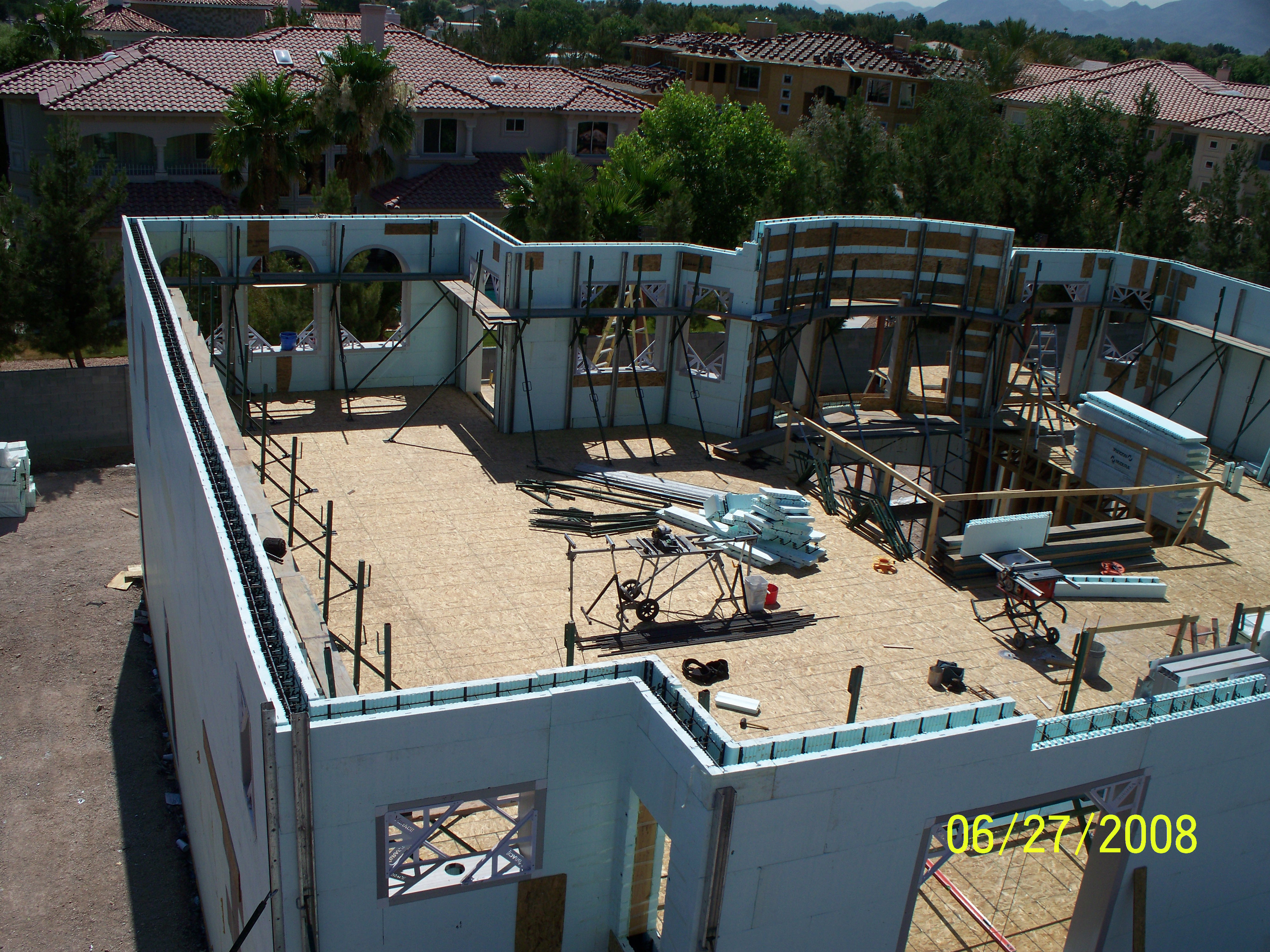
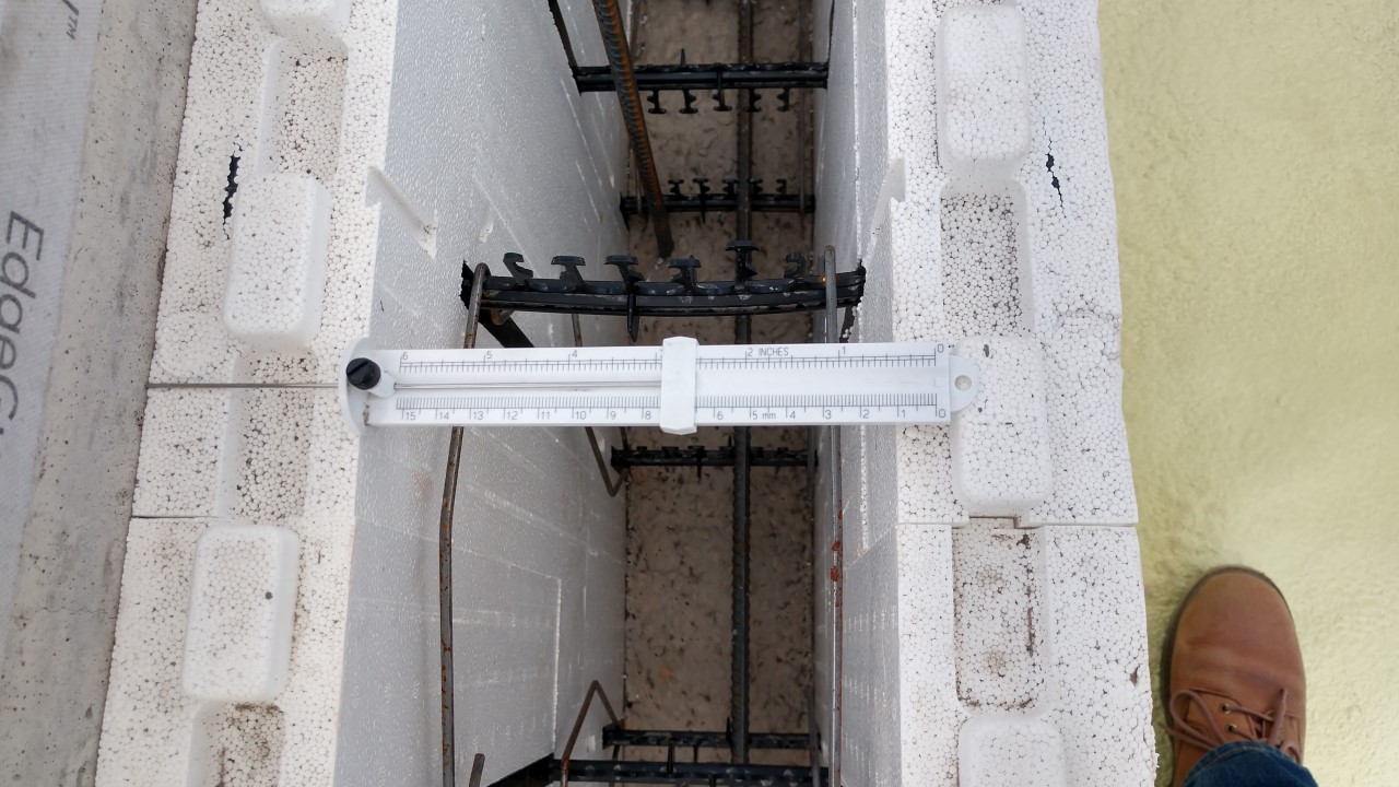
The ICF blocks are designed to interlock with one another. As the blocks are stacked, any required steel reinforcement is installed. Mechanical wall penetration sleeves and electrical conduits are also installed as the blocks are stacked. The ICF wall must be braced before being filled with concrete to keep the walls in place. See Figure 7. For more details on ICF construction, see the Insulated Concrete Forms (ICF) guide.
ICF walls are air-tight and contribute to a tight building envelope when air leakage around windows and doors and at the ceiling is addressed. Continuous insulation on both sides of the concrete is energy efficient with minimal thermal bridging. ICF blocks are available with varying levels of insulation and should be specified to meet energy code requirements.
Note that the inner layer of insulation will significantly diminish the thermal mass value compared to a concrete wall with all insulation on the exterior. ICF construction limits the benefits of passive heating and cooling strategies such as night flush, as these strategies require the thermal mass to be directly exposed to the inside air. See the Passive and Low-Energy Cooling guide for more information.
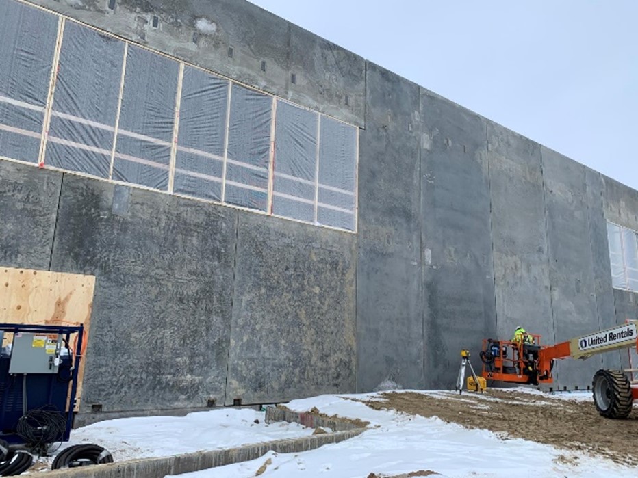
Poured Concrete Wall Construction provides very high thermal mass, with the flexibility to leave the thermal mass exposed to the inside and distributed throughout the home. Careful attention to detail is required for setting and preparing forms and installing steel reinforcement. Rebar must be installed as required for the region and wall size. Concrete forms require ties, pins, and wedges to be in place before pouring concrete, to avoid concrete leakage at seams and wall shifting during the pour. Applying oil on the forms can ease form removal. It is important to order concrete from the batching plant with the correct mix for the project and conditions. During placement in the forms, concrete should be compacted to avoid any voids in the finished wall. As with CMU wall construction, installing insulation on the exterior will provide the most benefit from thermal mass construction. See Figure 8.
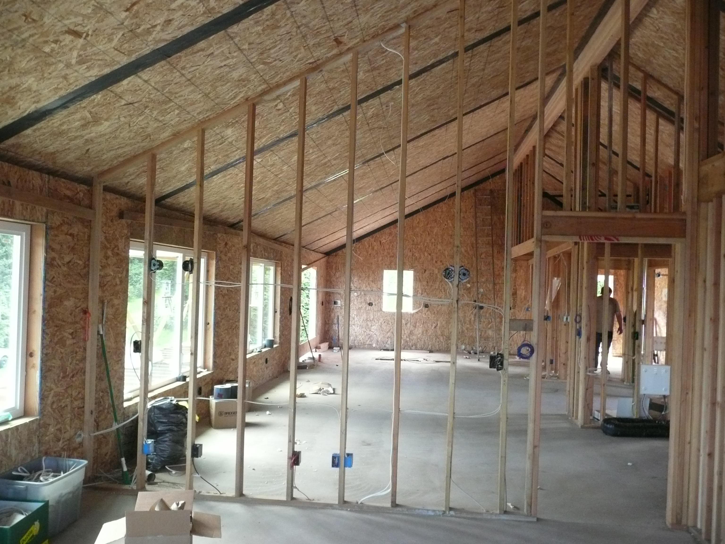
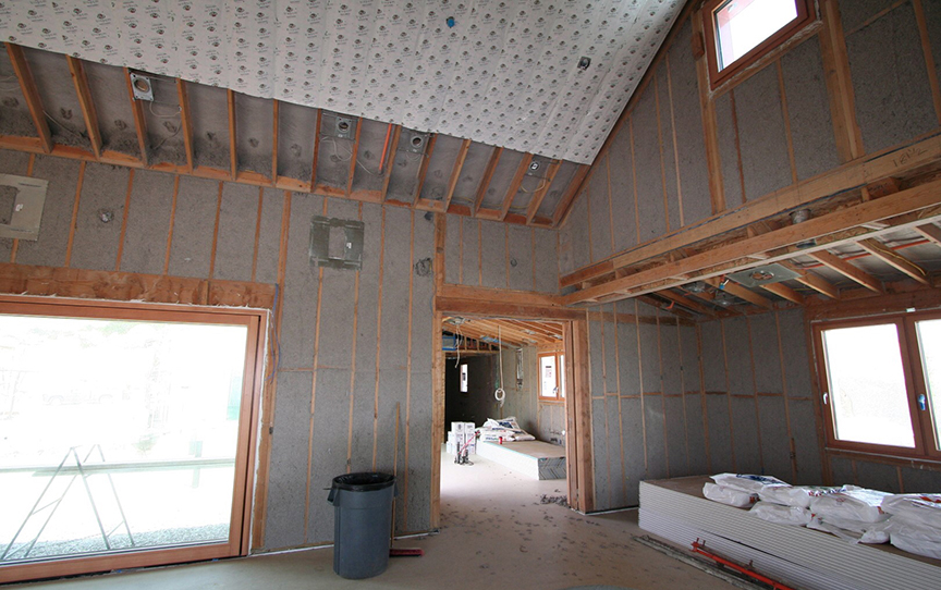
Poured Concrete Slab Floors can provide substantial thermal mass to masonry or wood-framed homes. Concrete slab floors are usually poured at or near grade, forming the lowest floor in the house. They can also be poured as the floor for upper stories as well. When poured on-grade, the slab should be insulated per code both under the slab as well as at the slab edges. Significant thermal bridging can occur when a slab is not insulated vertically at its edge. Slab floors may be reinforced using rebar, mesh, or reinforcing fibers mixed with the concrete before pouring. A vapor retarder should be placed under the slab to prevent moisture from the ground from migrating upwards into the conditioned space. As with all thermal mass, the floor must be exposed to the interior air in order to be useful in passive heating or cooling strategies. Stained and sealed concrete floor finishes allow the concrete to readily transfer heat to and from the indoor air, while carpet or wood flooring over the slab will diminish this benefit significantly. Figure 9 shows a second-floor slab in a wood-framed home.
Rammed Earth Wall Construction is an old technique of building walls using compacted natural raw materials like earth, chalk, lime, or gravel. Building with rammed earth requires a solid knowledge of soil type and an understanding of the construction process. This method may not be appropriate for wet environments. It is also a labor-intensive process that may be expensive compared to more conventional methods. It is particularly important to receive approval from the local building code authority, mortgage lender, and insurance company before proceeding with construction. Rammed earth has inherent insulation value; depending on the wall thickness, additional insulation may or may not be required.
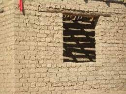
Adobe Wall Construction is an ancient construction method that traditionally consisted of sun-dried bricks made from a mix of soil, clay, and sand. Kiln-dried adobe bricks are now commercially available. Adobe construction requires close attention to detail for selecting suitable mortar, lintels for wall openings, and bond beams. Adobe construction has good thermal and acoustic properties, but it performs poorly during earthquakes. In earthquake prone areas, the design should consider adequate vertical and horizontal reinforcement, small wall openings, and lightweight roofing, and be approved by a design professional and the local building authority. See Figure 10.
Trombe Wall Construction is a method used for passive heating. A Trombe wall is a masonry wall designed to absorb heat during the day and release it to the building at night. A dark, heat-absorbing material is placed on the exterior of the mass wall and glass is placed over that, typically 1 to 6 inches away, to create an airspace. During the day, the solar radiation from the sun is absorbed by the dark surface and stored in the mass wall. During the night, the heat is conducted slowly inward through the mass wall and into the house. Ideally, the Trombe wall should face the direction of maximum solar radiation and can be used in conjunction with window placement and other design elements for passive heating.
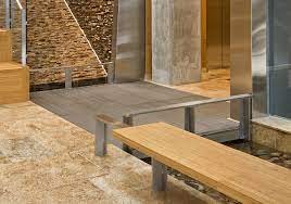
High-Mass Interior Finishes can increase the benefits of high thermal mass construction in all homes, including lightweight wood-framed structures. High-mass interior finishes have the advantage that they can easily be exposed and distributed. Examples include double layers of drywall, interior stucco, plaster on interior walls, tile flooring with concrete backer board, and concrete or granite countertops. See Figure 12.
Phase Change Materials (PCMs) are a relatively new alternative to masonry thermal mass construction that can be incorporated into various building components. PCMs are materials that undergo a change of phase from solid to liquid to absorb heat and from liquid to solid to release heat. They are a light-weight alternative to masonry construction that can be useful for passive cooling and passive heating, but this technology is not common in residential construction because it can be expensive and complex to integrate with other building components. See Figure 13.
Each PCM has a melting point temperature or temperature range. PCMs provide effective temperature regulation when the space temperature fluctuates above and below this melting point, but they provide very little value if the space stays above or below this temperature or range. In an extreme heat or extreme cold situation without adequate air-conditioning or heating, the space temperature may drift beyond the PCM’s melting point for an extended period of time. At this point, the PCM will be fully melted or solidified and will not help regulate temperature in a meaningful way. It has been shown that thermal mass construction using poured concrete performs better than PCMs under these conditions (Staszczuk and Kuczynski 2021).
When incorporating PCMs into a building’s construction, select suitable PCM material that is tested and approved for use in building envelopes. Select one of the following methods of incorporation of PCMs (Frigione, Lettieri, and Sarcinella 2019).
- Direct incorporation: add PCM in powder or liquid state directly to the construction material, like gypsum mortar, cement mortar, and concrete mixtures. While this is the easiest and most cost-effective method, its drawbacks include leakage of PCM during melting phase (which can increase risk of fire) or weakening of construction material properties.
- Immersion: Immerse porous construction material into the liquid PCM. This method can be incompatible with construction and can cause leakage or corrosion of reinforced steel when incorporated with reinforced concrete.
- Use PCMs that are microencapsulated (covered with shells, tubes, channels, and thin plates) or microencapsulated (micronized PCM is covered by unique polymeric material).
- Use shape-stabilized or form-stable PCMs (PCMs that have been modified to reduce or prevent leakage).
How to Integrate Thermal Mass Construction for Energy Savings and Resistance to Extreme Heat and Cold
- Determine the climate zone and the year-round weather conditions of the building site. If the area is well-suited to the use of high-mass construction, select materials with high thermal mass for walls or floors but ideally both. See the Climate tab for information on climates that can make the best use of high thermal mass.
- Ensure that you comply with all national and local building codes, any selected above-code programs, and manufacturer installation instructions.
- Select a wall construction type that provides high thermal mass.
- If using CMU or formed-concrete construction, install wall insulation on the exterior to take the most advantage of the wall’s thermal mass properties. CMU cavities can be filled with concrete to increase thermal mass.
- If using ICF construction, select the ICF block with the amount of insulation that meets local code.
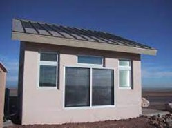
- In warmer climates, select exterior wall cladding such as light-colored stucco to help reflect solar radiation and reduce heat gain. The stucco will help to improve the thermal mass of the wall assembly, even where it is separated from the mass wall with insulation.
- Install interior wall finishes, such as double layers of drywall, stucco, plaster, or tile to increase the thermal mass of the wall assembly.
- Select floor construction that provides high thermal mass, ideally a concrete slab.
- If slab insulation is required, locate the insulation to optimize the thermal mass properties of the slab. For example, exterior perimeter slab insulation, installed vertically (i.e., not horizontally below the slab) can reduce heating and cooling loads while maintaining the thermal mass effect of the slab and ground below it. Locating insulation (or carpet) on top of the slab will greatly reduce its thermal mass benefit.
- Install tile and cement backer board to provide additional thermal mass for wood-framed homes.
- Integrate passive heating and cooling designs like building orientation, window glazing, and shading, light-colored reflective surfaces, ventilation, and landscaping to reduce heat gain in summer and increase heat gain in winter as appropriate for your location and home design. See the Passive and Low-Energy Cooling guide for more information.
Ensuring Success
Confirm that building-integrated thermal mass is a suitable strategy for your location by considering the characteristics of your climate: length and severity of heating season, length and severity of cooling season, and summertime diurnal temperatures. See Climate tab for more details.
Incorporate as many passive cooling strategies as practical along with thermal mass construction to help maintain a comfortable indoor temperature during periods of extreme heat and power outages. Ensure the thermal mass is distributed over a large area and is directly exposed to the indoor space.
Region
The benefit of thermal mass construction differs depending on climate region. Climates that can make good use of thermal mass for a significant portion of the year include cold climates with long heating seasons, hot-dry climates with long cooling seasons, or mixed-dry climates with substantial heating and cooling seasons.
For passive cooling and resistance to extreme heat, thermal mass is most effective in regions where the average daily temperature swings are high, particularly where the outdoor temperature ranges well above the indoor temperature during the day and well below the indoor temperature at night. Ideally, the location will have an average 24-hour temperature swing of 25oF or more during the summer. Large day-night temperature swings are more common across the western United States than in the eastern U.S. Numerous locations in IECC climate zones 3B, 3C, 4B, and 5B (portions of the Hot-Dry, Mixed-Dry, Marine, and Cold-Dry climate regions) have both high cooling design outdoor temperatures and an average 24-hour temperature swing of 25oF or more during the summer. Examples of some of these locations are shown in Table 1. IECC climate zones are shown in Figures 1.
For passive heating and resistance to cold snaps, thermal mass is most valuable in regions with colder winters, including IECC Climate zones 4 and higher, with the highest climate zones gaining the most value.
Thermal mass is not recommended for houses relying on passive cooling strategies in warm-humid climate zones (IECC climate zones 1A, 2A, and much of 3A).
| State | City | 1% Cooling Design Temp. (°F)* | Average Summertime Daily Temp. Range (May-Aug) (°F) | Climate Zone |
|---|---|---|---|---|
| Arizona | Flagstaff | 93 | >26 | 5B |
| Nogales | 98 | >24 | 3B | |
| Kingman | 100 | >25 | 3B | |
| Prescott | 92 | >24 | 4B | |
| California | Barstow | 107 | >27 | 3B |
| Livermore | 95 | >24 | 3C | |
| Chino | 98 | >25 | 3B | |
| Nevada | Carson City | 91 | >26 | 4B |
| Tonopah | 93 | >28 | 4B | |
| Fallon | 97 | >29 | 5B | |
| Caliente | 97 | >32 | 4B | |
| Texas | Pampa | 97 | >24 | 4B |
| Dalhart | 97 | >26 | 4B | |
| Marfa | 91 | >25 | 3B | |
| * When designing an HVAC system for a building, the cooling load is typically calculated using the "1% design temperature" - the outdoor temperature that is only exceeded for 1% of the time during a typical year - and constant indoor temperature, normally 75°F. Although this design temperature can be higher for hotter regions, they may not have high daily temperature difference (daily range) and hence would not benefit from thermal mass construction. | ||||

Training
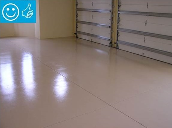
Right and Wrong Images
Source
Source
Source
Source
EPA guidance document providing information on moisture control in buildings.

Source
Compliance
Retrofit
It is best to incorporate thermal mass construction into a home when first built. However, there are a few opportunities to retrofit an existing home to incorporate thermal mass.
- Insulate the concrete walls on the exterior if they are uninsulated.
- Add an extra layer of drywall throughout the house.
- Add a plaster finish to interior walls.
- Add tile to walls and floors.
- Expose covered thermal mass in a slab by removing flooring and staining the slab to become the finished floor.
- Install high-mass countertops.
- Incorporate phase change material products.
More Info
References and Resources
*For non-dated media, such as websites, the date listed is the date accessed.
Contributors to this Guide
The following authors and organizations contributed to the content in this Guide.
Questions? Comments? Contact our webmaster.