

Scope
Install a continuous rigid air barrier or other supporting material to cap dropped ceilings or soffits.
- Rigid air barrier material could include rigid foam insulation, drywall, plywood, or OSB, among others.
- Install the air barrier flush with the surrounding ceiling.
- Seal all seams, gaps, and holes in the air barrier with caulk or foam before installation of attic insulation.
- Ensure that the air barrier is continuous and in full contact with the insulation.
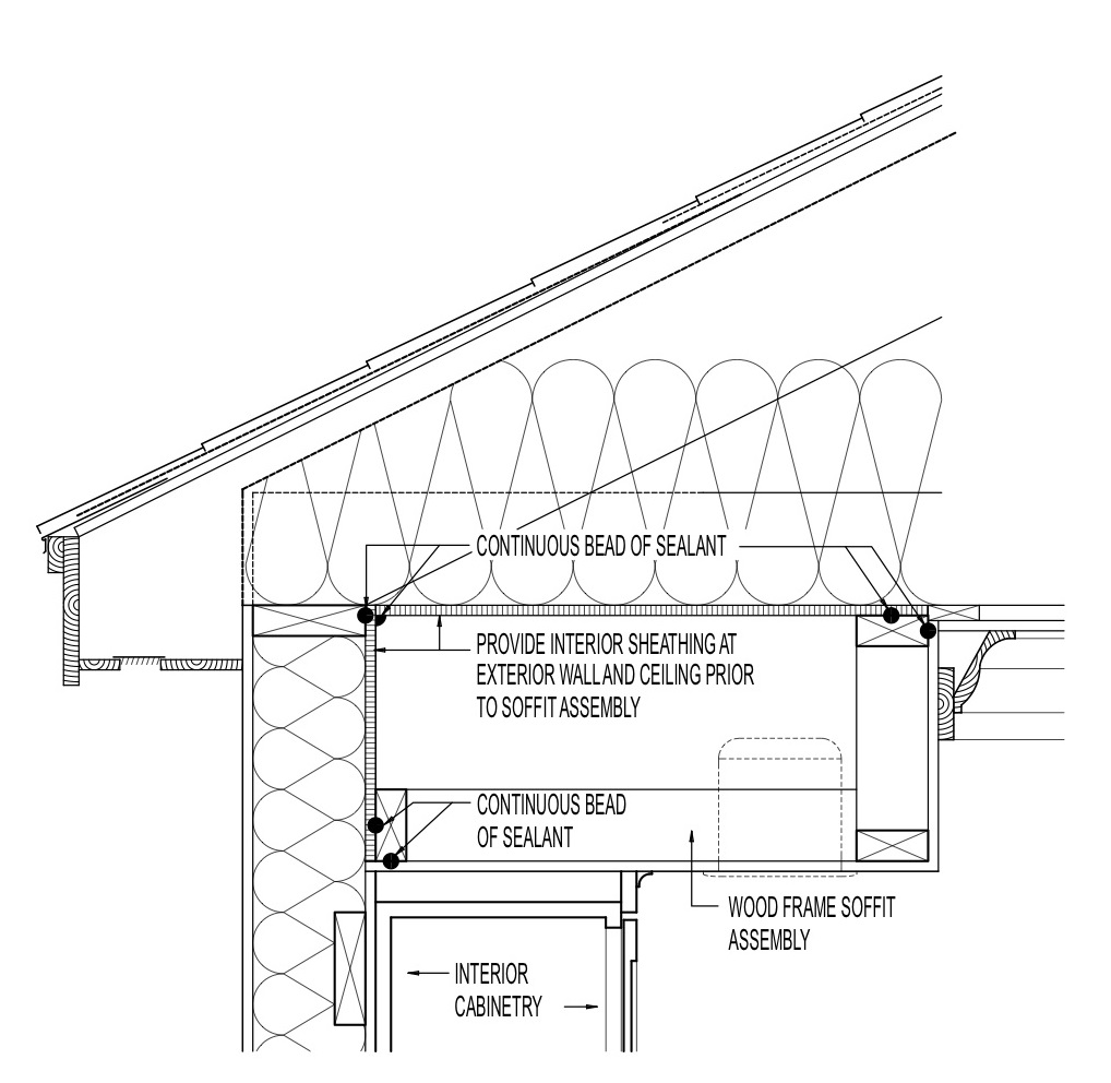
- If the dropped soffit runs along an exterior wall, ensure that an air barrier is installed on the interior side of the exterior wall insulation before installing the air barrier over the soffit.
See the Compliance Tab for links to related codes and standards and voluntary federal energy-efficiency program requirements.
Description
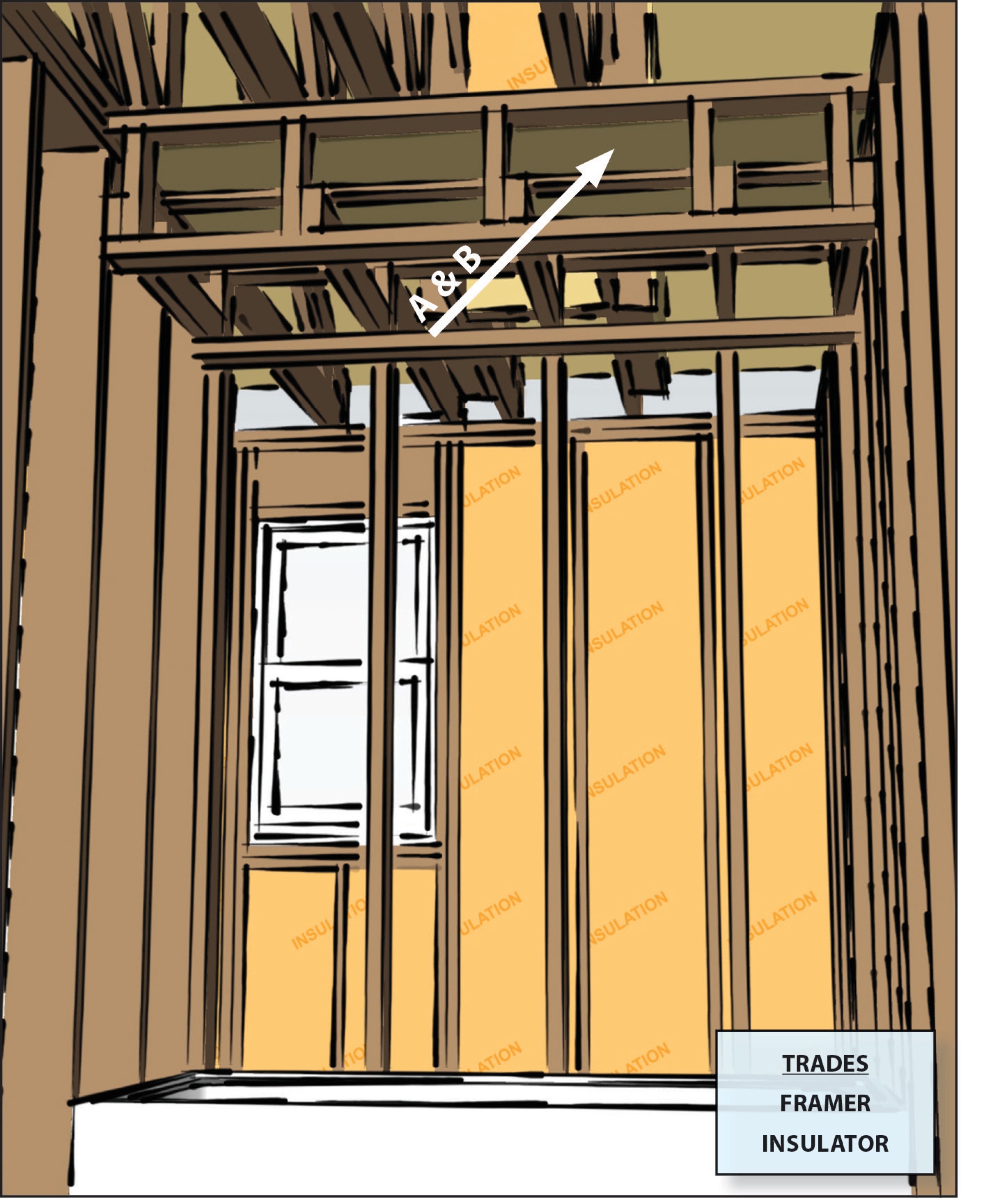
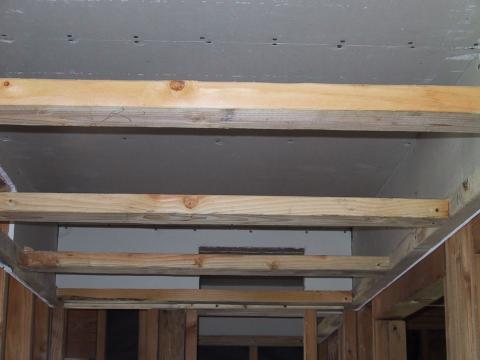
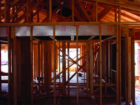
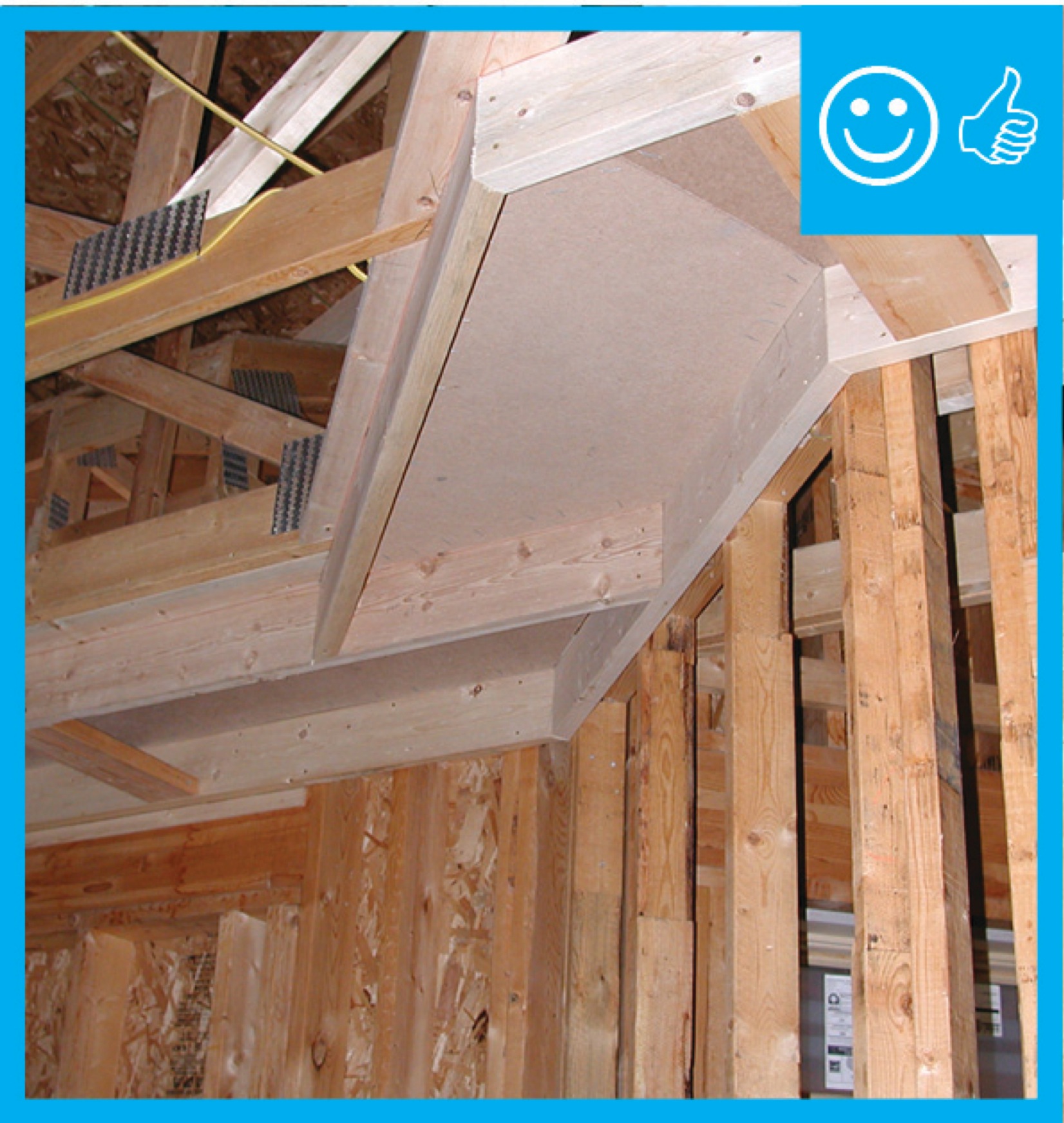
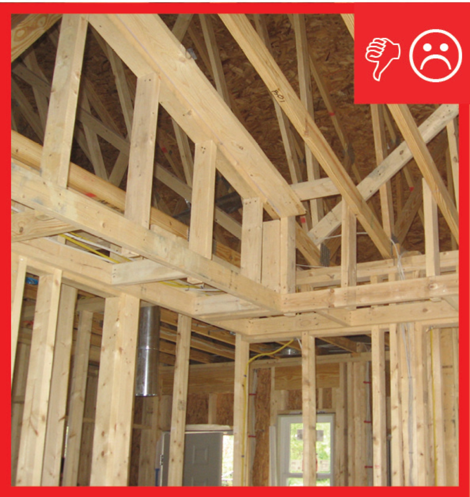
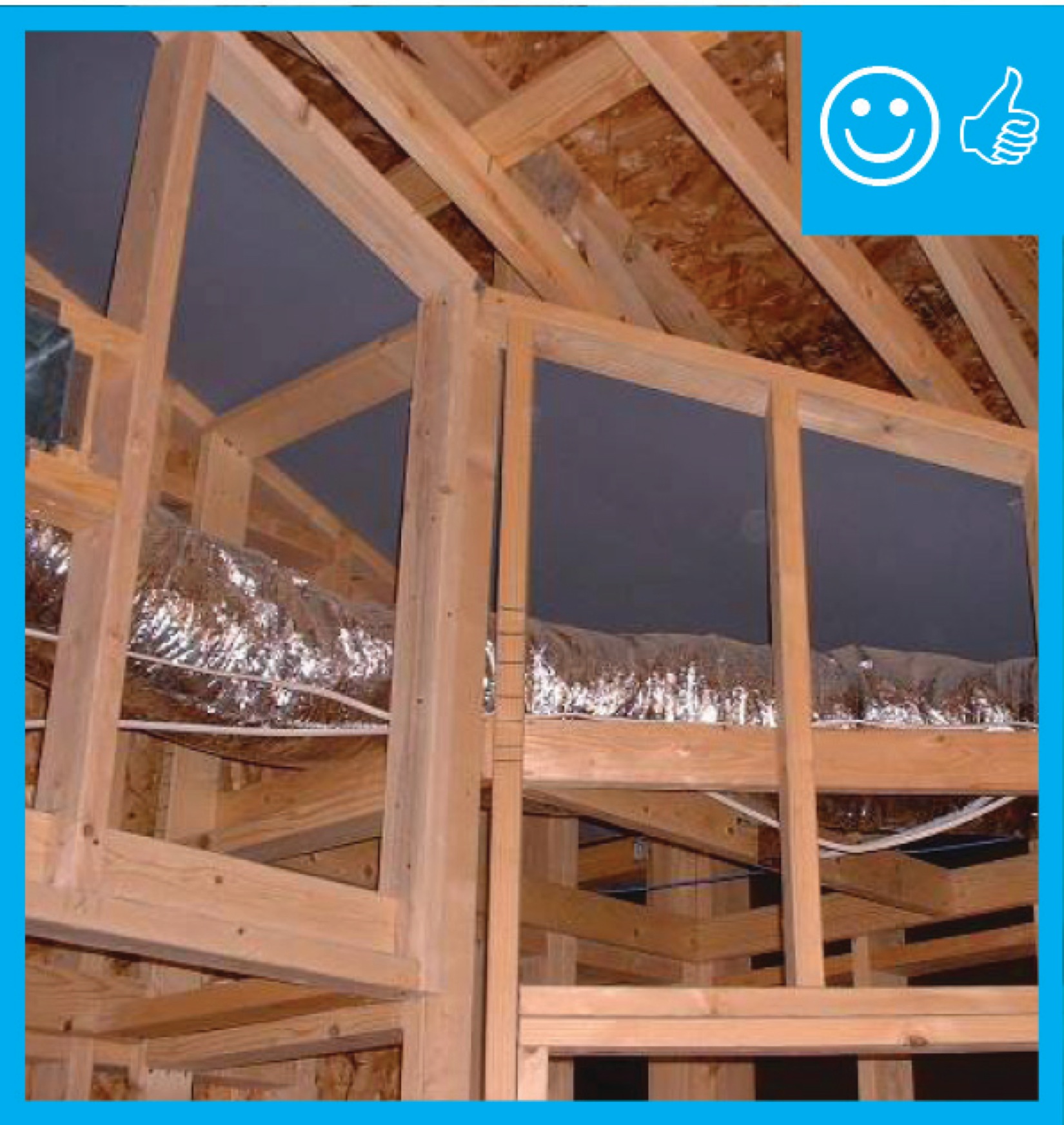
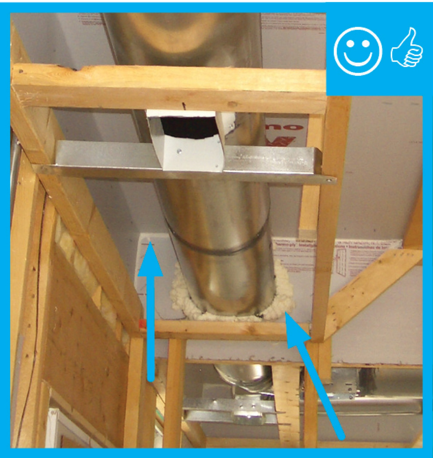
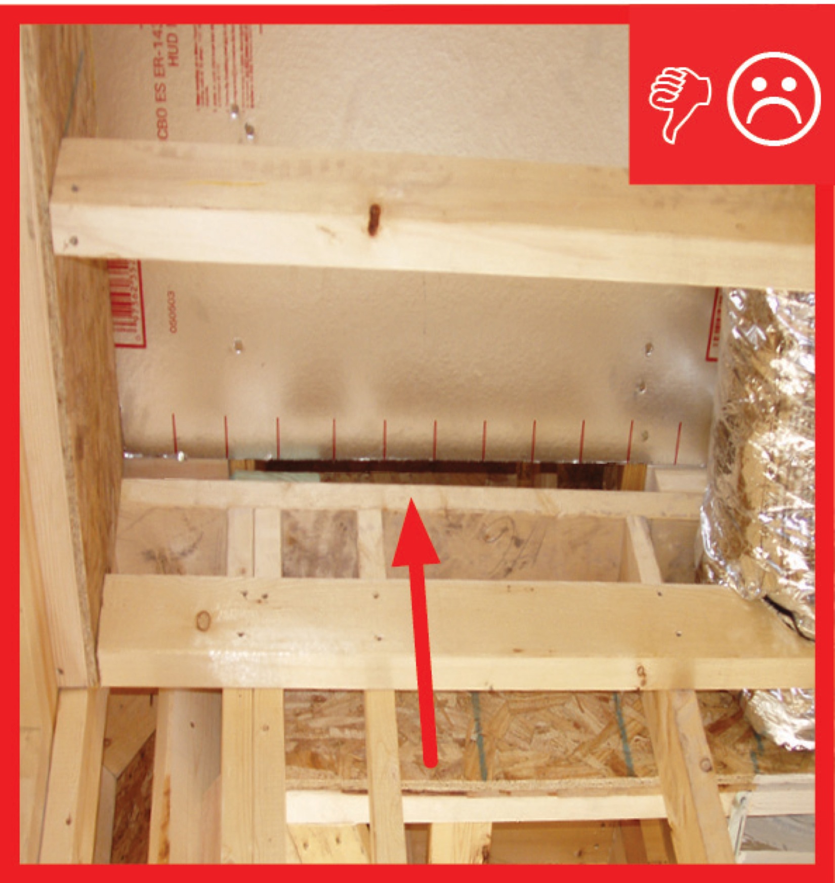
Soffits (dropped ceilings) found over kitchen cabinets or sometimes running along hallways or room ceilings as duct or piping chases are often culprits for air leakage. The space above the soffit should be covered with an air barrier material to stop conditioned air from escaping through the soffit and into the attic and to stop unconditioned air from a ventilated attic from coming through the open soffit into the home through air leaks in the soffit. If the soffit is along an exterior wall and there is no air barrier material covering the wall insulation, this unconditioned air can flow through the wall cavity robbing the insulation of its insulating ability. These air barriers are often overlooked due to a sequencing issue. The framer builds the soffit before the drywaller can get to the wall behind it, and when the drywaller installs gypsum board, the soffit is left open from above to install ducts or recessed can lights. An air barrier material like rigid foam, gypsum board, OSB or plywood should be installed over the top of the soffit framing, level with the rest of the ceiling drywall, and the edges of the material should be sealed with caulk. Then attic insulation can be installed above it to a level equivalent with that of the rest of the attic when the rest of the attic is insulated. If the soffit runs along an exterior wall, drywall or some other rigid air barrier material should be installed on the exterior wall, and air sealed to the top plate, before the soffit framing is installed.
These materials may be installed by insulators, framers, or drywallers. This task should be included in the contract for the appropriate trade depending on the workflow at the specific job site.
How to Air Seal a Soffit or Dropped Ceiling
For Ducts in an Interior Hallway
- Install the hallway framing for the sides of the soffit but not the bottom of the soffit.
- Install the air barrier for the ceiling and side walls of the soffit on the inside of the framing. Air barrier material may be gypsum board, OSB, plywood, or rigid foam. Caulk and fasten the air barrier to the framing. Caulk, mud, and tape to seal the seams between the top and sides of the soffit.
- Install ducts. Install framing for the bottom of the soffit. Caulk and fasten ceiling drywall for the bottom of the soffit.
- Install drywall on the hallway walls when the rest of the house is drywalled. Caulk, mud, and tape to airseal seams at the lower corners of the soffit to the hallway walls.
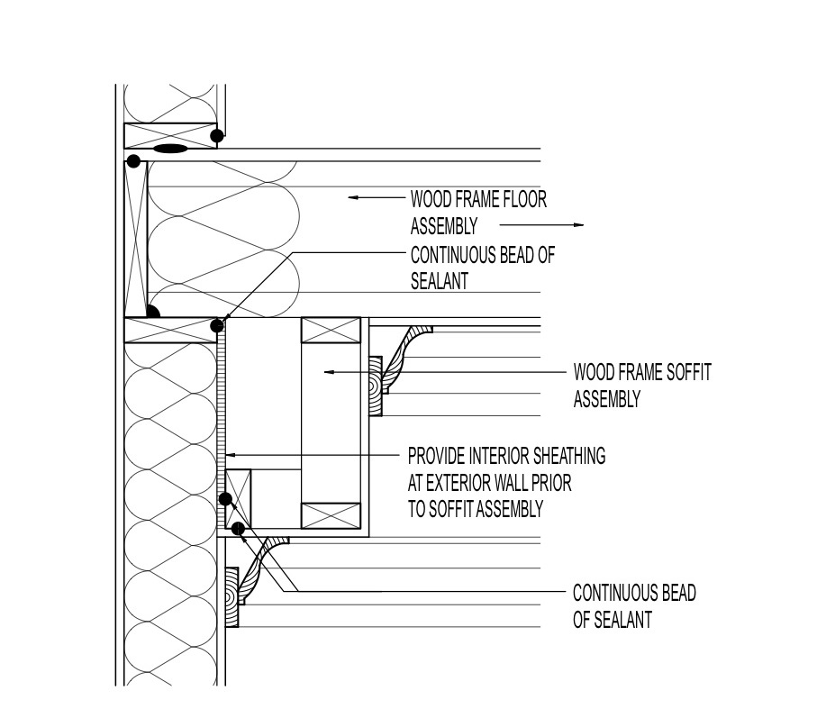
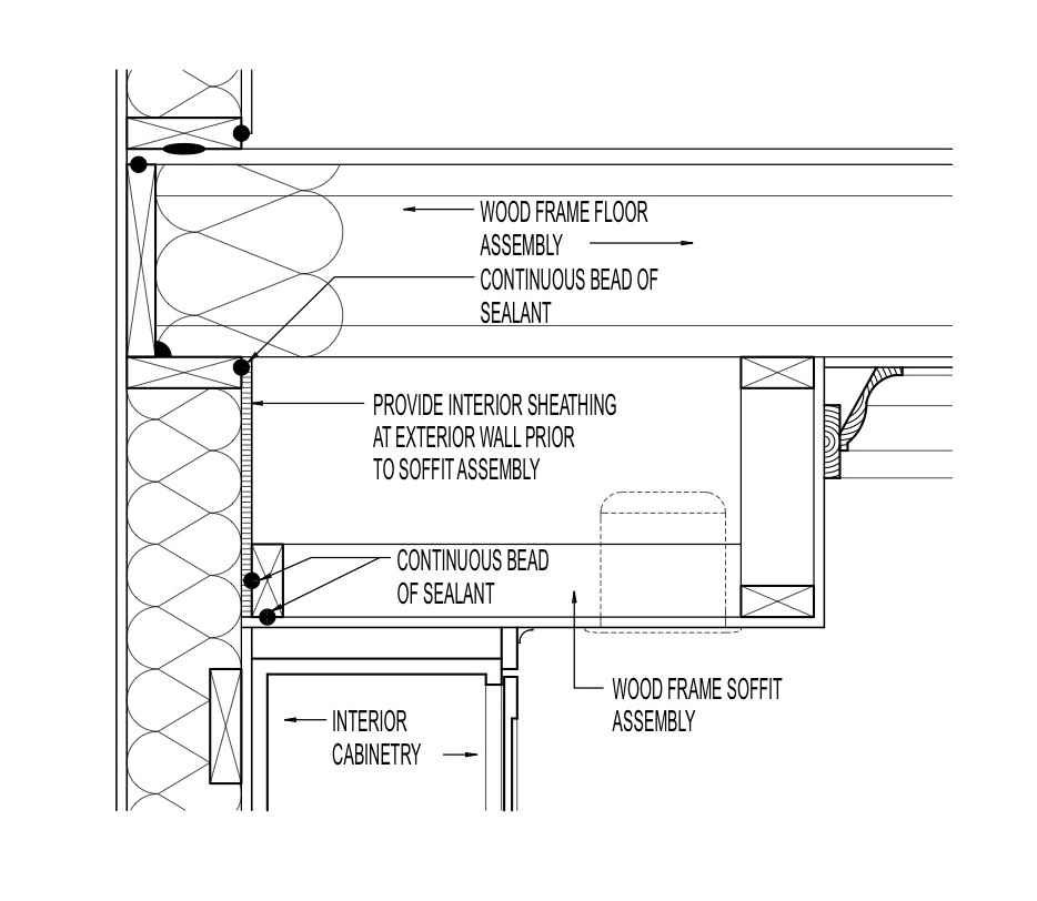
For Soffits on an Exterior Wall
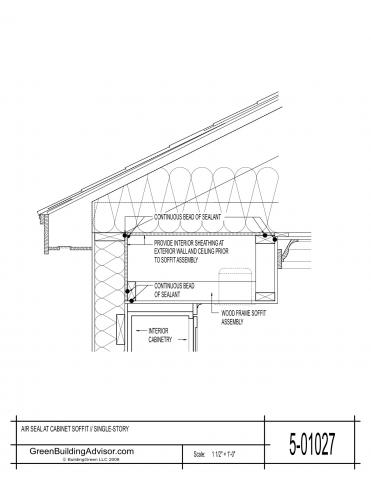
- Install cavity insulation in the exterior wall up to the top plate. Run a continuous bead of caulk along the top plate and install the drywall or other air barrier material on the wall and ceiling behind where the soffit will go. Caulk the seam where the wall and ceiling air barrier meet.
- Install framing for the soffit. Seal to the ceiling and wall air barrier material with a continuous bead of caulk.
- Install the drywall or other facing for the soffit. Seal to the soffit framing with a continuous bead of caulk. Install drywall on the remaining walls and ceiling. Caulk, mud and tape to seal the seams where these surfaces meet the soffit drywall. Install trim and cabinets if cabinets are being mounted under the soffit.
- In the attic, install insulation over the soffit as you would over the rest of the attic floor.
For Soffits with Recessed Can Lights
- If on an exterior wall, cover the exterior wall behind the soffit with an air barrier material first. Attach the air barrier with a continuous bead of caulk along the top plate and use screws or nails to secure in place.
- Install framing for the soffit.
- Attach drywall to the side(s) and bottom of the soffit with a bead of caulk and fasteners. Caulk, mud, and tape the drywall at the seams to air seal it.
- Install can lights. Do not fill the soffit with insulation; insulation will be installed above the soffit.
- Cut air barrier material to fit between joist bays on the attic side of the ceiling. Notch for wiring if necessary. Fasten the air barrier material in place over the soffit with caulk. Caulk edges and caulk around wiring. Cover with attic insulation.
Ensuring Success
Blower door testing, conducted as part of whole-house energy performance testing, may help indicate whether air leakage at soffits has been successfully sealed. Some building codes and high-performance home labeling programs require that builders meet specified infiltration rates at the whole-house level. See the “Compliance” tab for specified infiltration rates for several codes and program. An infrared camera may also be helpful in detecting air leakage at the soffit, if a sufficient temperature difference exists between the attic and the conditioned space of the house.
Region
Minimum Insulation Requirements for New Homes as Listed in the 2009, 2012, 2015, and 2018 IECC
Install insulation in amounts that meet or exceed code-required levels for your climate zone. Please see this table for the minimum insulation requirements for ceilings, walls, floors, and foundations in new homes, as listed in the 2009, 2012, 2015, and 2018 IECC and IRC.
The map in Figure 1 shows the climate zones for states that have adopted energy codes equivalent to the International Energy Conservation Code (IECC) 2009, 12, 15, and 18. The map in Figure 2 shows the climate zones for states that have adopted energy codes equivalent to the IECC 2021. Climate zone-specific requirements specified in the IECC are shown in the Compliance Tab of this guide.

Source
2012 edition of code establishing a baseline for energy efficiency by setting performance standards for the building envelope (defined as the boundary that separates heated/cooled air from unconditioned, outside air), mechanical systems, lighting systems and service water heating systems in homes and commercial businesses.

Source
2021 edition of code establishing a baseline for energy efficiency by setting performance standards for the building envelope (defined as the boundary that separates heated/cooled air from unconditioned, outside air), mechanical systems, lighting systems and service water heating systems in homes and commercial businesses.
Training
Right and Wrong Images

Source
Guide describing details that serve as a visual reference for each of the line items in the Thermal Enclosure System Rater Checklist.
Source
Guide describing details that serve as a visual reference for each of the line items in the Thermal Enclosure System Rater Checklist.
Source
Guide describing details that serve as a visual reference for each of the line items in the Thermal Enclosure System Rater Checklist.
Source
Guide describing details that serve as a visual reference for each of the line items in the Thermal Enclosure System Rater Checklist.

Source
Guide describing details that serve as a visual reference for each of the line items in the Thermal Enclosure System Rater Checklist.
Source
Guide describing details that serve as a visual reference for each of the line items in the Thermal Enclosure System Rater Checklist.
Source
Guide describing details that serve as a visual reference for each of the line items in the Thermal Enclosure System Rater Checklist.
Videos
CAD Files

Compliance
Retrofit
SCOPE
Cover and air seal dropped soffits to prevent air leakage into the attic.
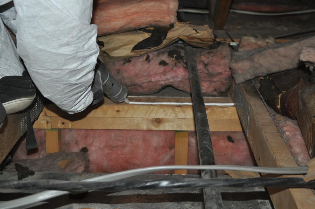
- Assess the attic for leaks, mold, rot, knob and tube wiring, and asbestos and remediate before air sealing.
- Remove insulation to expose the dropped soffit framing.
- Install a rigid air barrier of plywood, OSB, drywall, or rigid insulation over the open soffit.
- Air seal the edges of the rigid barrier and any seams in the barrier.
- Air seal around any penetrations.
- Install insulation over the soffit to match the adjacent attic insulation.
- Measure the insulation level in the attic and increase to code-required minimum or higher, as necessary or desired.
- If the dropped soffit runs along an exterior wall, check for, and install if needed, a solid air barrier along the exterior wall.
- See the Scope and Description tabs for additional guidance.
Guidance for mitigating asbestos-related issues from HUD, EPA, NIH, OSHA and FEMA is available in Homeowner's and Renter's Guide to Asbestos Cleanup After Disasters and Asbestos: Worker and Employer Guide to Hazards and Recommended Controls.
For more information on conditions that may be encountered when working in attics in existing homes, see the assessment guide on attics.
See the U.S. Department of Energy’s Standard Work Specifications for more on air sealing and working in attics. Follow safe work practices as described in the Standard Work Specifications.
DESCRIPTION
Many older homes have dropped ceilings or soffits as duct or piping chases or as architectural features within the home, for example soffits over cabinets or around the edges of a room, or sometimes constructed as decorative arches in doorways. These may or may not be filled with insulation, usually do not have a continuous air barrier, and often are a source of air leakage and heat loss (especially when installed along an exterior wall if no solid air barrier is installed along the exterior wall). Dropped ceilings and soffits can be identified from a walk-through of the home. The contractor can note these locations on a sketch of the home, then visit the attic for further inspection to see which soffits are missing air barriers on top, and along the side if located on an exterior wall. The soffits should be covered using a rigid air barrier material like plywood, OSB, drywall, or rigid foam that is caulked and fastened in place following the instructions listed below and in the Description tab. (See especially the section “For Soffits with Recessed Can Lights,” Steps 1 and 5.) This work will be performed inside the attic so use safe work practices and be aware of hazardous conditions as described in the attic assessment guide.
How to Air Seal and Insulate a Dropped Ceiling or Soffit
- Identify locations of soffits and dropped ceilings from inside the home.
- Assess ceilings, attics, and roofs for signs of leaks, mold, rot, knob and tube wiring, and asbestos and repair or remediate as necessary before proceeding with air sealing.
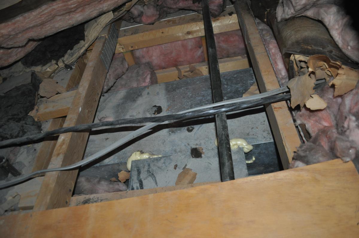
- Remove and set aside attic insulation to reveal the open cavity of the dropped soffit. See Figure 1.
- If the dropped soffit runs along an exterior wall, ensure that exterior wall insulation is covered with a solid air barrier before air sealing the top of the soffit. If no solid air barrier covers the exterior wall insulation, cut plywood, OSB, drywall or rigid insulation to fit; apply caulk to the surface of the framing; install the solid barrier with nails or screws; and caulk or tape the seams. See Figure 3 on the Description tab. Then proceed with air sealing the top of the soffit as described above.
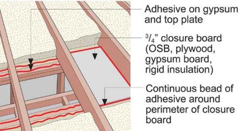
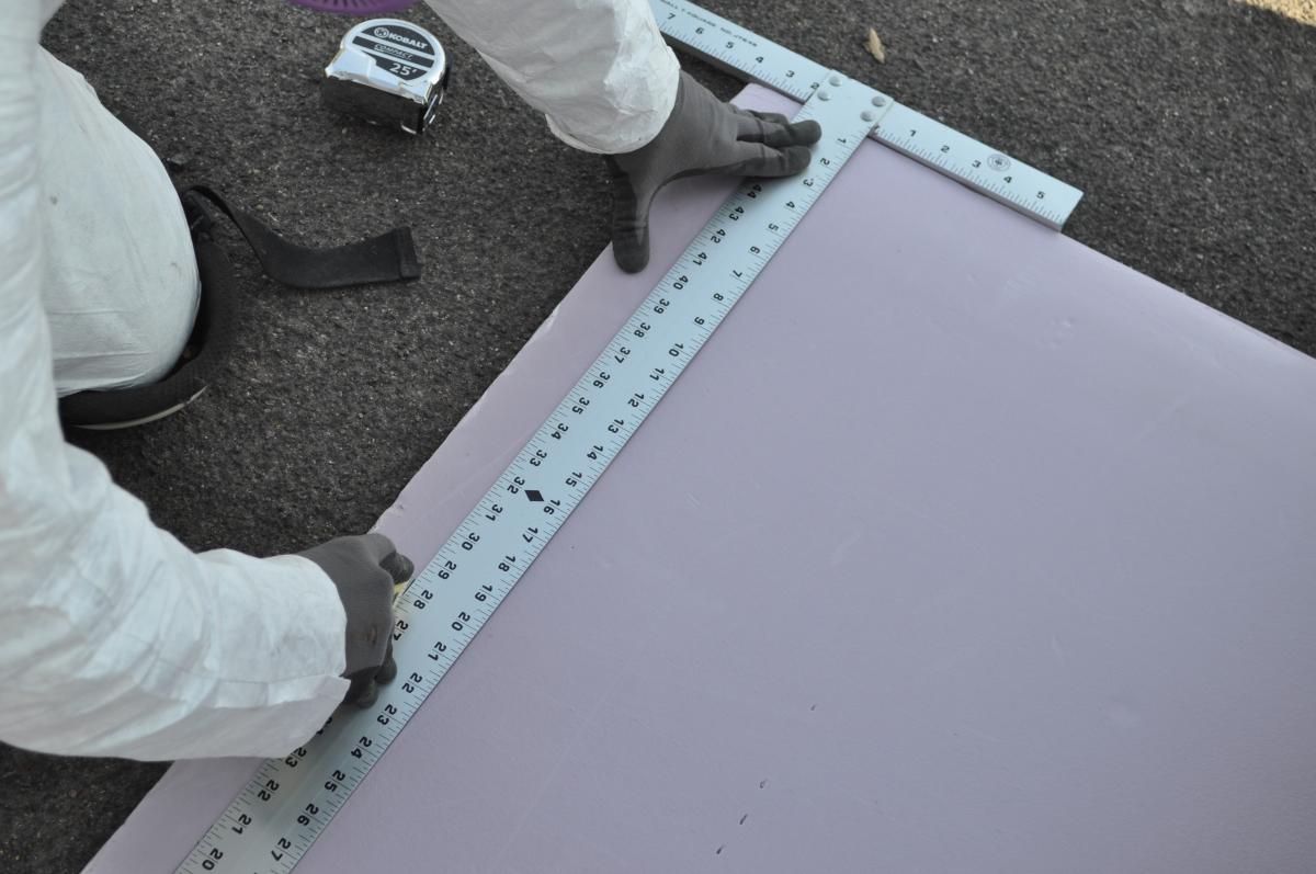
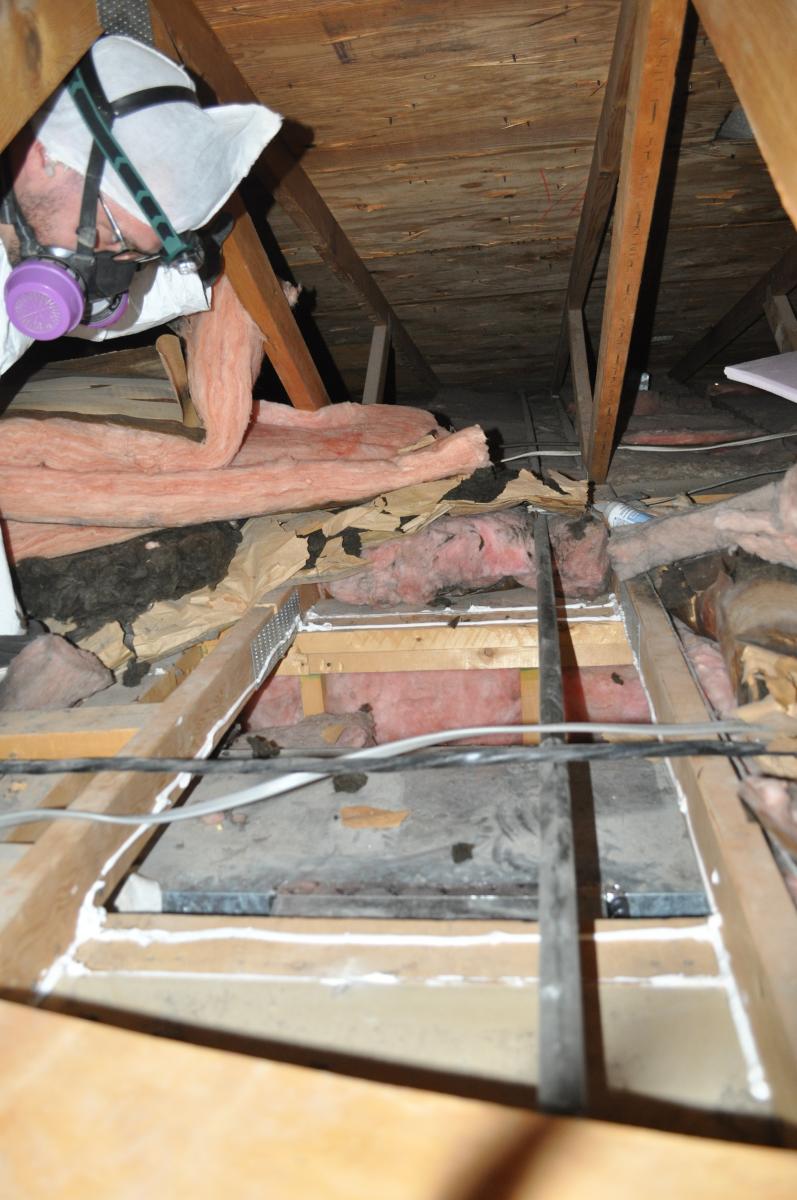
- Cut plywood, OSB, drywall, or rigid insulation to fit between the framing members forming the boundaries of the dropped soffit (see Figure 2 below and Description tab, Figure 4).
- Apply caulk to the top and side surfaces of the framing where the solid barrier material will be placed (Figures 3 and 4).
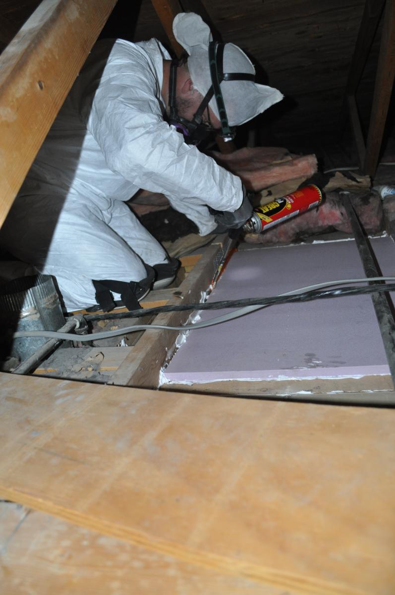
- Position solid material over the opening and fasten in place with sealant and nails or screws (Figure 5).
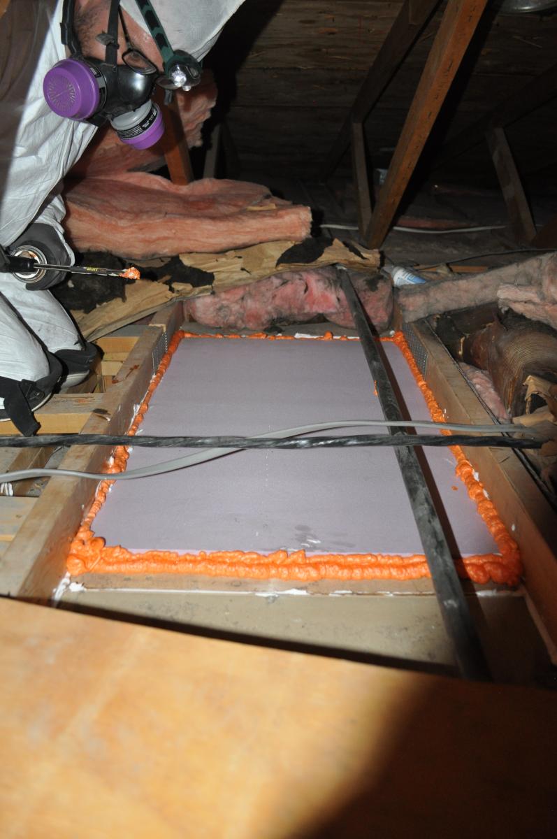
- Seal the edges of the plywood, OSB, or rigid insulation closure where it meets the framing with sealant (Figure 6). Seal joints in the plywood, OSB, or rigid insulation with sheathing tape or sealant. Caulk or foam around any penetrations (for lights and wiring, for example).
- Install insulation over the rigid board to match the adjacent attic insulation.
- Measure the insulation level in the attic and increase to code-required minimum or higher, as necessary.
- Note that it is not necessary to install insulation inside the soffit since insulation will be provided above the closure. Insulation should be removed from within the soffit if non-ICAT rated recessed lights are installed.
COMPLIANCE
See Compliance tab.
More Info
Case Studies
References and Resources
*For non-dated media, such as websites, the date listed is the date accessed.
Contributors to this Guide
The following authors and organizations contributed to the content in this Guide.
Pacific Northwest National Laboratory
Building Science Corporation, lead for the Building Science Consortium (BSC), a DOE Building America Research Team
Sales
Fully Aligned Air Barriers = Whole-House Draft Barrier
Technical Description
A whole-house draft barrier is a continuous layer of air-tight materials that block air leaks. This barrier can be integrated with other materials to also function as a water barrier, thermal barrier, and vapor barrier. For example, rigid foam insulation can be used to block thermal flow as well as air flow when seams are sealed with tape, caulk, adhesives, or liquid-applied sealants. Some rigid foams have an integrated water control layer as well. Additionally, drywall can serve as an interior air barrier when the seams are taped and spackled, and caulk, spray foam, or gaskets are used to seal around wiring, plumbing, and other penetrations. It also serves as the vapor barrier when finished with paint. Insulation should be in full contact with the air barrier layer.
Questions? Comments? Contact our webmaster.