

Scope

Provide a strong and continuous load path from the roof to the foundation to avoid structural damage and to keep the building intact during hurricanes and other extreme storms.
Best practice steps for new construction:
- Determine the wind design velocity and if the house is in a hurricane-prone region.
- For hurricane-prone regions, a licensed structural engineer must determine the continuous load path connections.
- For areas where design wind speed is less than that of hurricane-prone regions, a prescriptive design approach may be used:
- Ensure that roof framing, floor framing, wall framing, and foundations are constructed in accordance with all applicable building codes.
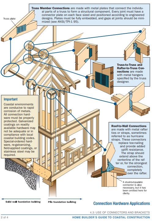
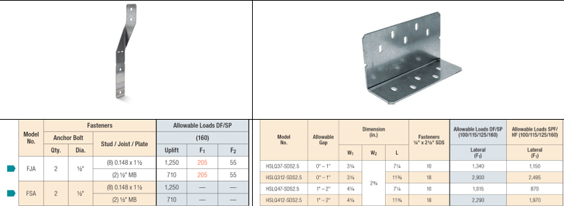
- Specify and install a continuous load path, such that the building has positive connections from the roof to the foundation to resist and transmit wind uplift and lateral shear loads to the ground (see Description tab for above-code connectors):
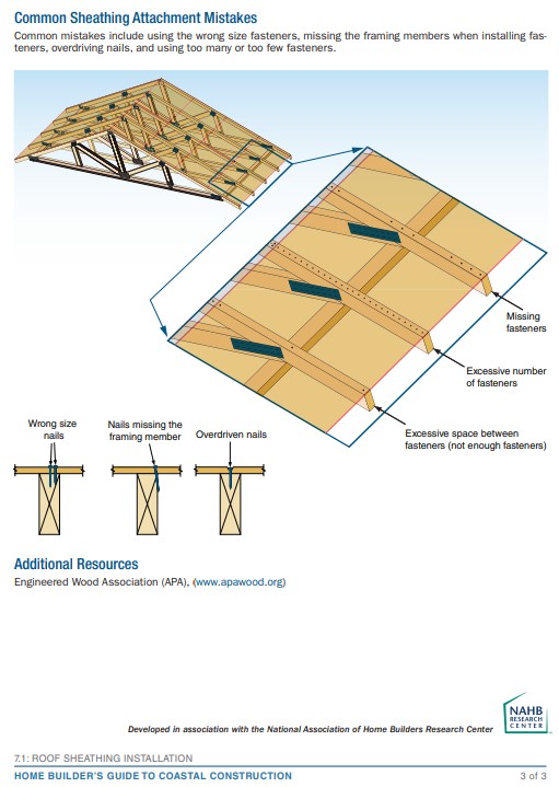
- Install roof sheathing-to-framing connections
- Install roof-to-wall connections
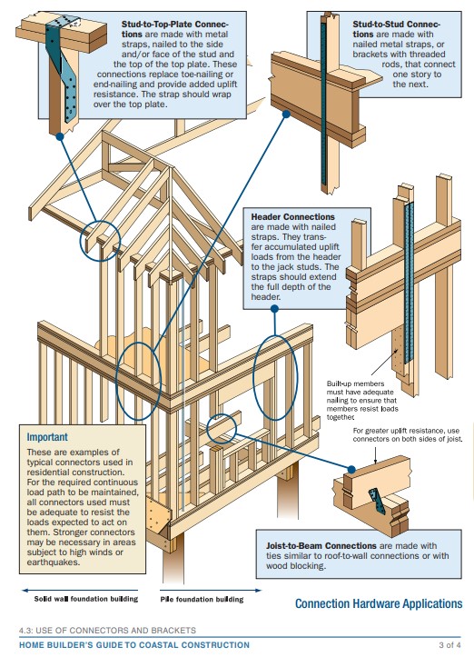
- Install wall above-to-below connections
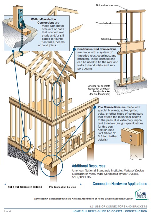
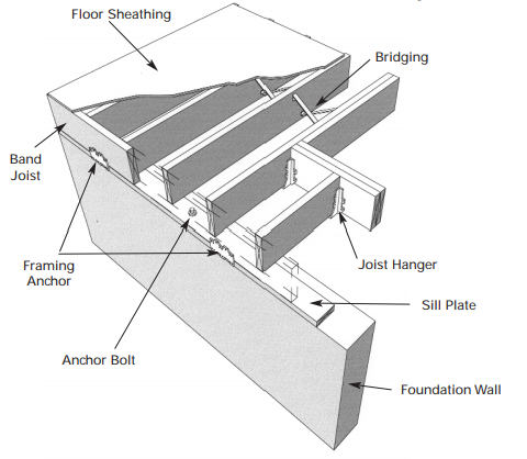
- Install wall-to-foundation connections
- Install any chimney-to-roof member connections.
See the Compliance Tab for links to related codes and standards and voluntary federal energy-efficiency program requirements.
Description
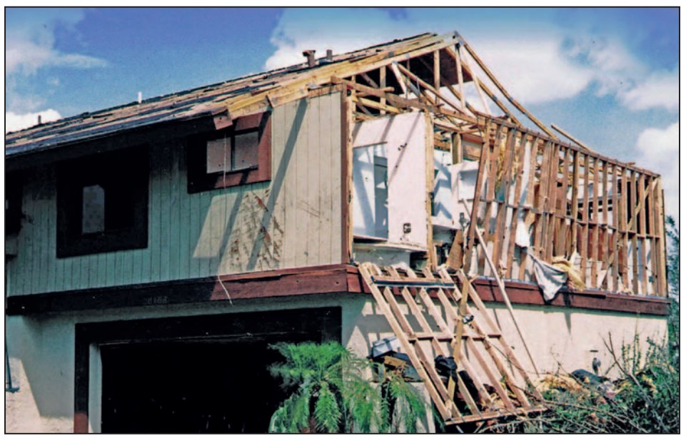
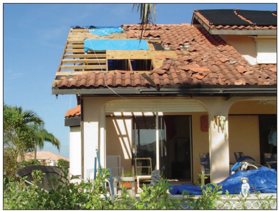
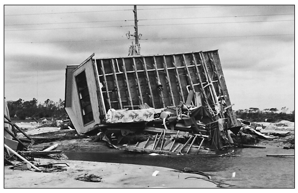
Load path failures can lead to the loss of parts or all of the building assembly (Figure 1). This guide presents an overview of the continuous load path, with a focus on connections between building component assemblies (roof, wall, foundation) for houses in hurricane-prone regions, high-wind areas, and earthquake-prone regions. Establishing a continuous load path is a requirement in the IBHS FORTIFIED Home Hurricane Standard and IBHS FORTIFIED Home High Wind Standard for the FORTIFIED Gold designation.
Source
Volume II of a two-volume report providing a comprehensive approach to design, construction, and renovation of homes located in coastal environments.
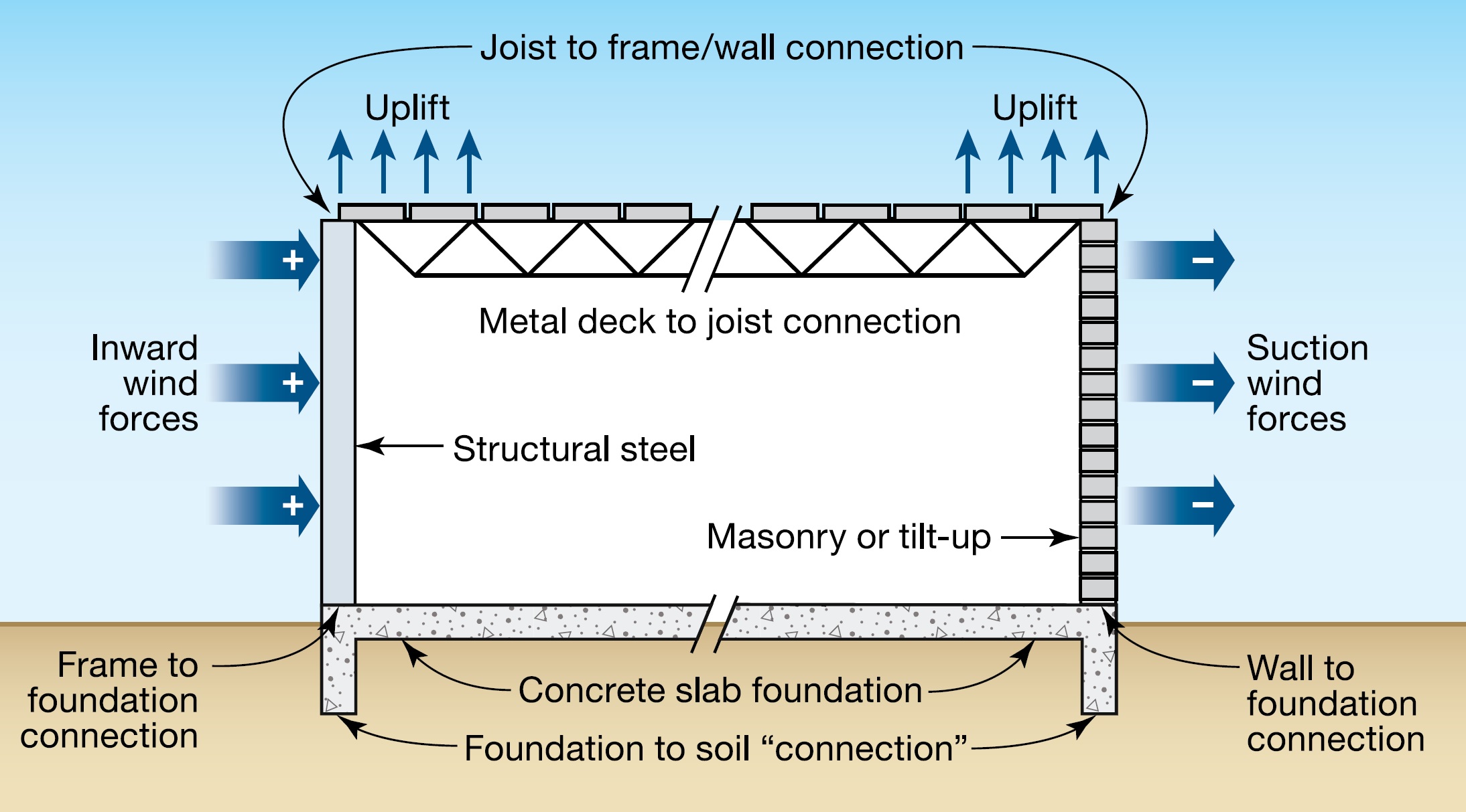
Buildings must be constructed with a strong and continuous load path from the roof to the foundation to avoid structural damage and to keep the home intact during hurricanes, high winds, and earthquakes (FEMA 232 2006).
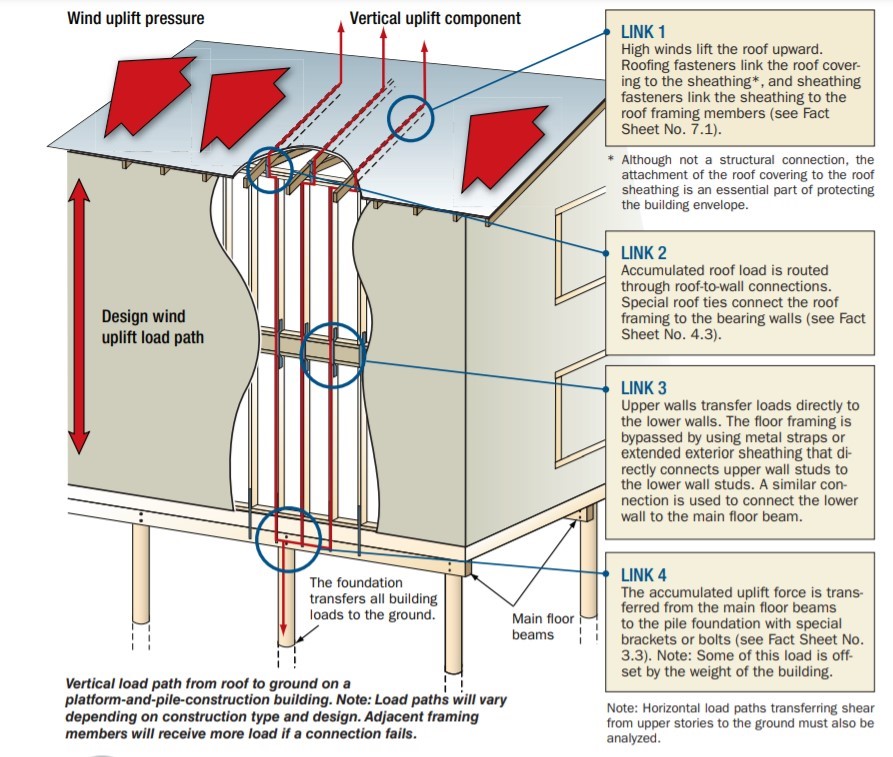
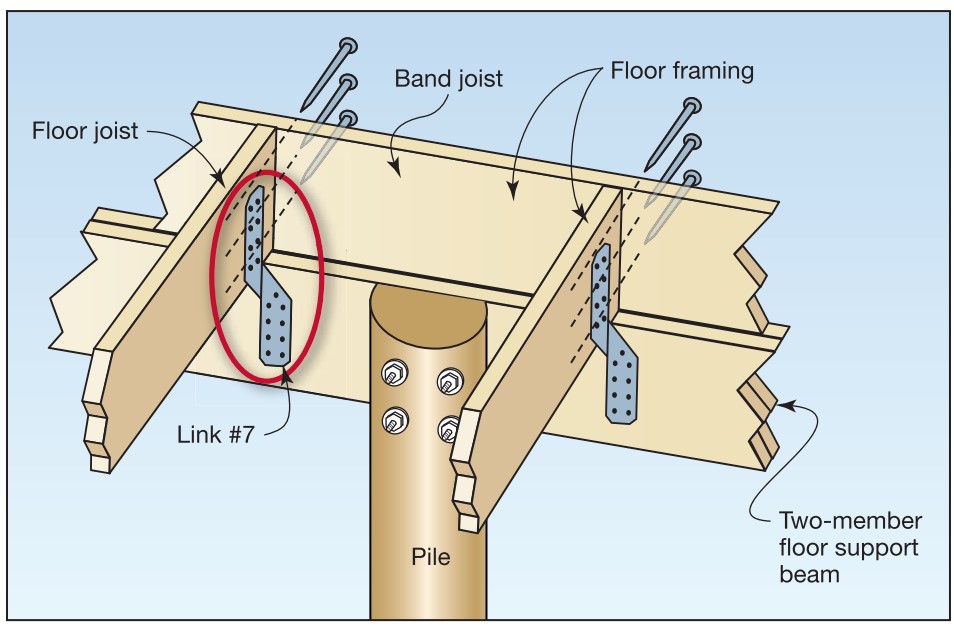
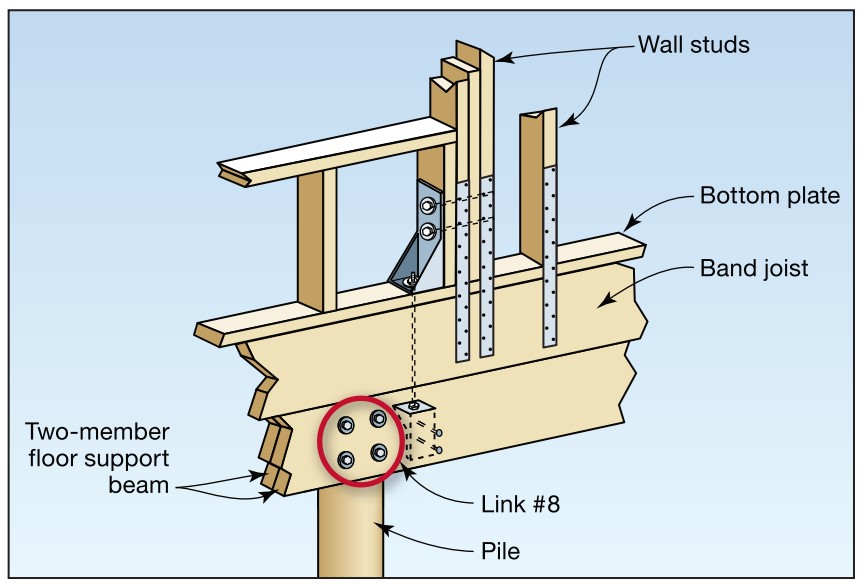
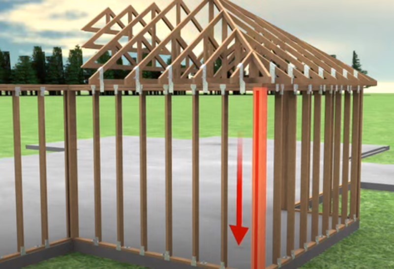
The term continuous load path describes the structural condition required to resist all loads acting on a building. Vertical loads include downward gravity forces (weight of the building) and uplift forces from wind. Horizontal (lateral) loads include wind loads perpendicular to a wall (out of plane) and parallel to a wall (in plane or shear). Flood and seismic events can present both vertical and horizontal loads. A continuous load path must transfer all vertical and horizontal loads to the ground. Figures 2, 3, and 4 below illustrate the concept of a continuous load path.
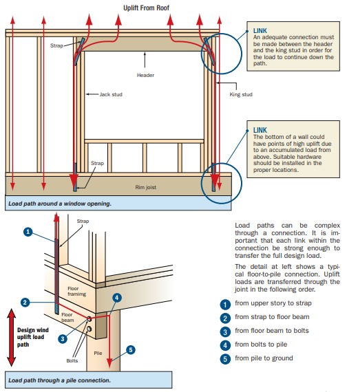
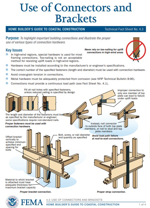
The connections between major building component assemblies (i.e., roof, walls, floors, and foundations) tend to be the weakest link within a load path. If a connection fails, an alternative load path will form. If the members and connections in the new load path are not strong enough, progressive failure can occur (Figure 1). Loads must be routed around openings such as windows and doors (Figure 4). Accumulated loads on headers are transferred to the studs on the sides of the opening. See the Training tab for several examples of connector details to transfer loads from one building component to another.
The International Residential Code (IRC) states that constructing buildings as prescribed by the code will result in a system that provides a complete load path for the transfer of loads from their point of origin through the load-resisting elements to the foundation (IRC R301.1). The IRC requires structural assemblies and their attachments to be capable of resisting design wind pressures. For some high-wind regions, the IRC requires design in accordance with other methods, including the International Building Code.
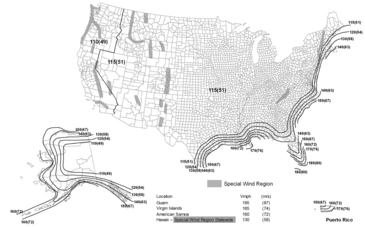
Homes located in coastal high-wind areas including hurricane-prone regions generally require enhanced attachment that can withstand greater wind speeds than the rest of the country. The IRC defines “hurricane-prone regions” as areas along the Atlantic and Gulf Coasts where wind velocity is greater than 115 mph, and Hawaii, Puerto Rico, Guam, the Virgin Islands, and American Samoa. (See the IRC wind map in the Climate tab). Confirm with the local building department if the house is in a hurricane-prone region and if local requirements exceed those of the IRC.
Source
Report providing guidance on how to improve the wind resistance of existing residential buildings in Mississippi and across the Gulf Coast.
Source
Report containing 37 fact sheets that provide technical guidance and recommendations concerning the construction of coastal residential buildings.
Source
Report containing 37 fact sheets that provide technical guidance and recommendations concerning the construction of coastal residential buildings.
Table R602.3(3) of the 2018 IRC specifies minimum fastening (nailing) requirements for various components of wood-framed construction, including roof rafter or roof truss to wall top plate; wall bottom plate to floor framing; floor framing to sill or top plate below; and wood structural panels for subfloors, walls, and roofs. Section R602.10 of the IRC provides prescriptive construction details and requirements for braced wall lines and braced wall panels for buildings exposed to different wind speeds.
Section 2304.10.6 of the International Building Code specifies requirements to a ensure continuous load path. It requires the members to be secured where the wall framing members are not continuous from the foundation sill to the roof.
The Insurance Institute for Business and Home Safety® (IBHS) offers guidance, best practices, and voluntary construction standards and programs for building in disaster-prone areas including hurricane and high-wind zones. The IBHS FORTIFIED HOME™ standard is designed to make homes more resilient and durable; guidance is available for new construction and existing homes in hurricane zones and high-wind zones. There are three levels of FORTIFIED Home: FORTIFIED Roof™ focuses on the roof; FORTIFIED Silver focuses on roof overhangs, opening protection, gable ends, and attached structures; FORTIFIED Gold focuses on tying all components of the structure together. The continuous load path is addressed in FORTIFIED Gold.
The IBHS FORTIFIED Home Hurricane Standard requires that a design professional registered in the state where the home is located must incorporate the continuous load path in the home’s design plan for new construction.
The IBHS FORTIFIED Home High Wind Standard provides prescriptive measures for a continuous load path for one-story or two-story buildings where the distance between shear walls is less than or equal to 2.5 times the building width. The measures are in addition to the normal fastening schedules specified in the IRC for new homes. For existing homes, the standard requires analysis by a licensed structural engineer for program certification, although the standard does provide some prescriptive retrofit measures.
Note that IBHS defines high wind areas as areas where the design wind velocity is less than or equal to 115 mph. The term high wind is not defined by the IRC. The IBHS definition of a hurricane-prone region is consistent with the IRC, that is, coastal locations where the design wind velocity is greater than 115 mph. So, in essence, the IBHS definition of high wind areas includes all areas of the continental United States that are outside of hurricane-prone regions.
The primary groups of prescriptive measures for the FORTIFIED Home High Wind Standard are shown here; see the Compliance tab for full details:
- Specify minimum, or better, roof sheathing thickness, roof sheathing attachment, and roof framing structure for trusses and rafter system.
- Anchor the roof structure to the exterior wall below using metal straps.
- Specify requirements for interior shear walls.
- Specify construction of exterior walls and interior shear walls.
- Install wall-to-wall connections for multi-story wood frame buildings.
- Specify strapping requirements for openings in wood frame exterior walls.
- Anchor floor system and exterior walls to foundation.
- Install hold-downs connecting exterior walls and interior shear walls to the foundation.
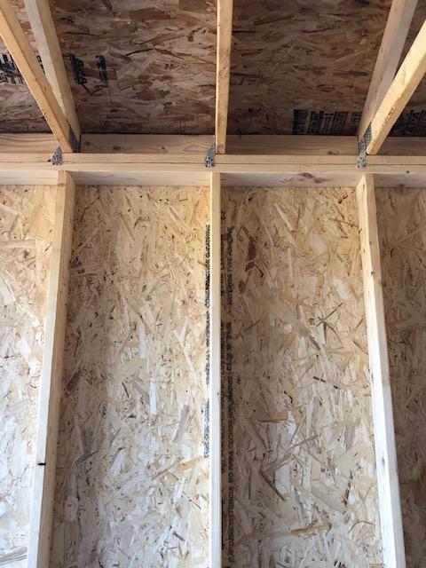
- Install blocking within floor assemblies as required.
- Specify gable end bracing requirements.
How to Provide a Continuous Load Path for New Construction
- Determine the wind design velocity and if the house is in a hurricane-prone region (See Climate Tab).
- For hurricane-prone regions, a licensed structural engineer must determine the continuous load path connections.
- For areas where design wind speed is less than that of hurricane-prone regions, a prescriptive design approach may be used:
- Ensure that roof framing, floor framing, and wall framing are constructed in accordance with all applicable building codes.
- Specify and install a continuous load path, such that the building has positive connections from the roof to the foundation to resist and transmit wind uplift and lateral shear loads to the ground (see Description tab for above-code connectors):
- Install roof sheathing-to-framing connections
- Install roof-to-wall connections
- Install wall above-to-below connections
- Install wall-to-foundation connections
- Install chimney-to-roof member connections
Example Details for New Construction from the Fortified Home High Wind Standard
- Requires metal straps to connect the roof to the wall to meet the load requirements shown below (Table 1):
Table 1. Roof-to-Wall Connector Minimum Capacities Based on Roof Span and 24-in. Spacing between Rafters and Trusses (Source: FORTIFIED Home High Wind Standard).
| Roof Span (ft) | 12 | 16 | 20 | 24 | 28 | 32 | 36 |
| Strap Capacity (lb) | 275 | 335 | 395 | 455 | 510 | 570 | 630 |
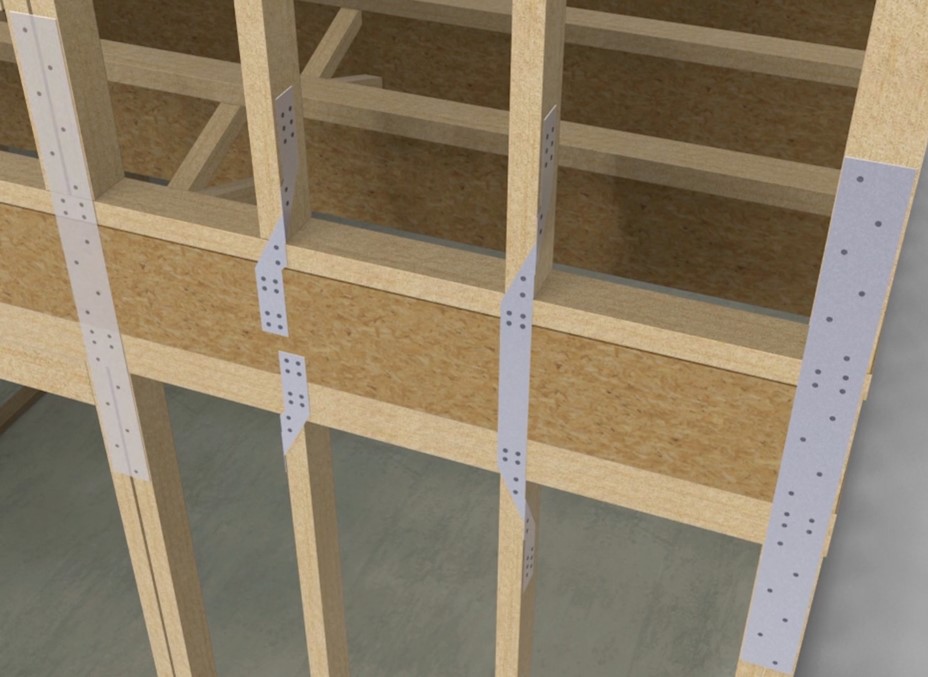
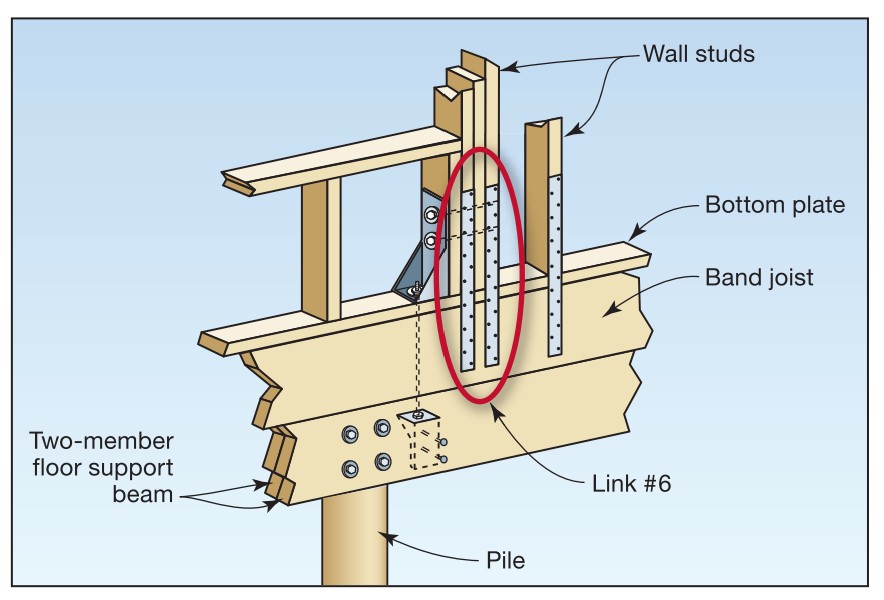
- Connect walls above-to-below to resist cumulative uplift and applicable shear forces using one of the following methods:
- Install metal straps for connecting wall studs from the wall above to the wall studs in the wall below or from the wall studs above to the rim board and from the rim board to the wall studs below. Straps can be installed on each stud or at some other convenient spacing not to exceed 8 ft.
- Use a minimum of 4 ft. continuous sheathing that spans across the floor depth to connect the upper wall to the lower wall with the specified number of nails (see Table 2) in the wall studs above the floor and wall studs below the floor. Nail spacing along the studs should not be less than 3 in.
Table 2. Number of 8d common, 10d box, or 8d ring-shank nails in each stud required to transfer
loads from studs in wall above to studs in wall below based on roof span indicated
and a stud spacing of 16 in. (Source: FORTIFIED Home High Wind Standard).
| Roof Span (ft) | 12 | 16 | 20 | 24 | 28 | 32 | 36 |
| Number of nails in each top and bottom stud for load transfer through continuous sheathing | 2 | 3 | 4 | 4 | 5 | 6 | 6 |
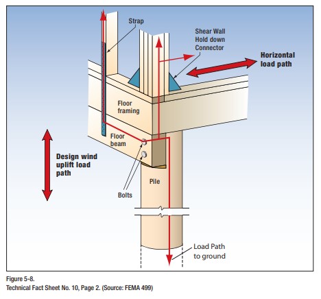
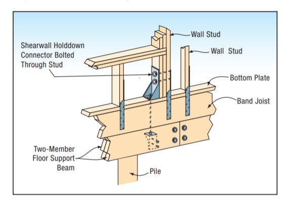
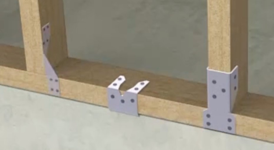
- Connect ground wall-to-foundation to resist cumulative uplift and applicable shear force.
- Bolt the shear wall hold-down connector through the stud. See Figure 5.
- Specify chimney framing and its connection to roof support members.
Source
Report containing 37 fact sheets that provide technical guidance and recommendations concerning the construction of coastal residential buildings.
Ensuring Success
For a durable continuous load path, it is recommended to hire a licensed structural engineer to specify all building connections, ensure compliance with local building codes, and comply with the requirements defined by the IBHS Fortified Home program.
Region
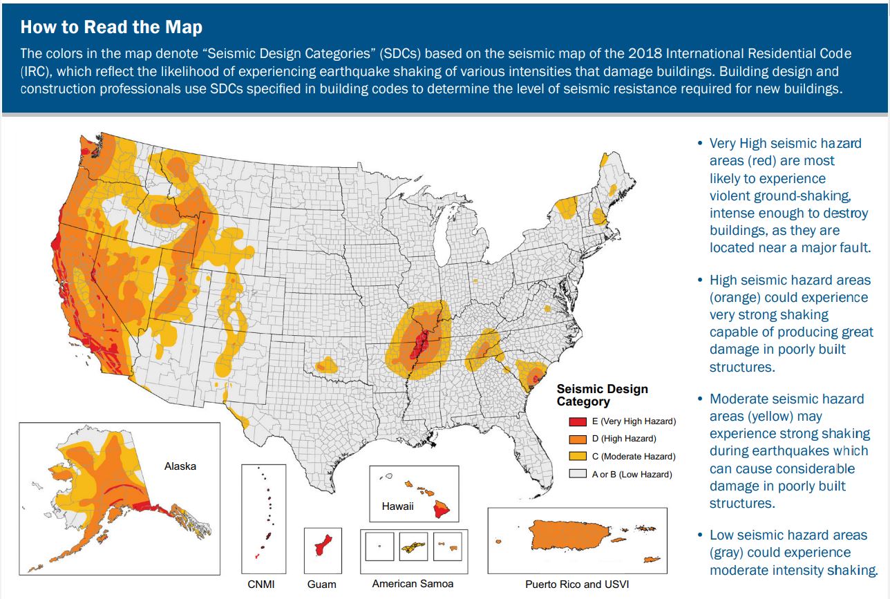
Continuous load path connections are important for all locations but are critical in regions prone to hurricanes, high winds, earthquakes, tornadoes, and floods to reduce the risk of structural damage and failure.
Source
2018 edition of code for residential buildings that creates minimum regulations for one- and two-family dwellings of three stories or less, bringing together all building, plumbing, mechanical, fuel gas, energy and electrical provisions for one- and two-family residences.
Source
2018 edition of code for residential buildings that creates minimum regulations for one- and two-family dwellings of three stories or less, bringing together all building, plumbing, mechanical, fuel gas, energy and electrical provisions for one- and two-family residences.
Training
Right and Wrong Images
Source
Report containing 37 fact sheets that provide technical guidance and recommendations concerning the construction of coastal residential buildings.
Source
Report containing 37 fact sheets that provide technical guidance and recommendations concerning the construction of coastal residential buildings.
Source
Report containing 37 fact sheets that provide technical guidance and recommendations concerning the construction of coastal residential buildings.
Source
Report containing 37 fact sheets that provide technical guidance and recommendations concerning the construction of coastal residential buildings.
Source
Report containing 37 fact sheets that provide technical guidance and recommendations concerning the construction of coastal residential buildings.
Source
Volume II of a two-volume report providing a comprehensive approach to design, construction, and renovation of homes located in coastal environments.
Source
Website describing the Insurance Institute for Business & Home Safety (IBHS)'s Fortified Home program which offers home builders standards and guidance for constructing and renovating homes for increased disaster resistance.
Source
Website describing the Insurance Institute for Business & Home Safety (IBHS)'s Fortified Home program which offers home builders standards and guidance for constructing and renovating homes for increased disaster resistance.
Source
Volume II of a two-volume report providing a comprehensive approach to design, construction, and renovation of homes located in coastal environments.
Source
Volume II of a two-volume report providing a comprehensive approach to design, construction, and renovation of homes located in coastal environments.
Source
Volume II of a two-volume report providing a comprehensive approach to design, construction, and renovation of homes located in coastal environments.

Source
Volume II of a two-volume report providing a comprehensive approach to design, construction, and renovation of homes located in coastal environments.
Source
Volume II of a two-volume report providing a comprehensive approach to design, construction, and renovation of homes located in coastal environments.
Source
Volume II of a two-volume report providing a comprehensive approach to design, construction, and renovation of homes located in coastal environments.

Source
Source
Report covering the planning, design, construction, and operation of residential and community safe rooms. Written for architects, engineers, building officials, local officials and emergency managers, and prospective safe room owners and operators.
Source
Document from IBHS explaining how to inspect homes for earthquake preparedness and retrofit solutions for homes that have suffered structural damage as a result of earthquakes.
Source
Source
Source
Videos


Compliance
Retrofit
IBHS Requirements for Compliance for Existing Homes / Retrofit
Determining if an existing home has a continuous load path is difficult since the connections that are required to meet the continuous load paths are concealed by finished materials including drywall, trim boards, exterior claddings, etc. FORTIFIED Home High Wind Standards require a licensed structural engineer to perform an analysis for an existing home to provide opinions about whether an adequate continuous load path exists.
Basic requirements for the retrofit of existing homes to meet the FORTIFIED Gold requirement include:
- Roof Construction and Framing
- Ensure truss framing does not exceed 24 in. o.c. The existing truss members should appear to be in sound condition. Wood members of any truss should not be damaged or deteriorated and all truss connector plates must be in good condition.
- Ensure the roof rafter and ceiling joist framing member size, spacing, span, and framing complies with the minimum requirements of the IRC.
- The roof rafter framing should either be braced rafter construction or collar ties or ridge strap construction.
- Wall Construction and Framing
- Fasten the bottom wall to the foundation and the top of the wall to the floor framing systems with sufficient horizontal diaphragm capacity.
- Protect the portions of the walls in contact with soil by water-resistant materials.
- Properly support the floor framing system and sufficiently connect to safely transmit all applicable gravity, uplift, and lateral forces to the structural support system below.
More Info
References and Resources
*For non-dated media, such as websites, the date listed is the date accessed.
Contributors to this Guide
The following authors and organizations contributed to the content in this Guide.
Questions? Comments? Contact our webmaster.