

Scope
Design or retrofit the chimney for adequate support and water protection.
- Provide adequate connection of the chimney to roof framing to make the chimney more resistant to toppling in strong winds and seismic activity.
- Install flashing that is properly integrated with the roof flashing to keep water out of the chimney and roof assemblies.
See the Compliance tab for links to related codes and standards and voluntary federal energy-efficiency program requirements.
Description
One of the largest penetrations in a residential roof assembly is a chimney. Chimneys typically have numerous requirements beyond that of venting products of combustion. They must be adequately connected to the roof structure to resist wind and seismic loads based on site design wind speed and exposure category. Chimneys must also be waterproofed to resist rainwater entry during high wind events such as hurricanes.
This guide provides guidance on securing and waterproofing chimneys to resist toppling rainwater entry during high wind events such as hurricanes. In addition, this guide also covers construction guidelines for chimneys built on homes in earthquake zones. The guidance is applicable to both new construction and the re-roofing of existing roof assemblies.
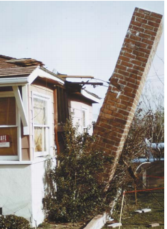
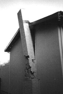
It is common for chimneys to significantly extend or protrude above roof surfaces in order to provide sufficient “draft” for the venting of products of combustion. This tends to expose the chimney surfaces to higher wind pressure differences than those acting on the field of the roof assembly. Chimneys, especially tall, narrow chimneys or those made of brick or stone that protrude high above the roof, are at an increased risk of damage and are prone to collapse under seismic forces. Not only will the collapse of a chimney damage the structural integrity of the roof and home, but they pose a significant risk of injury for occupants (FEMA P-530, 2020). These forces can be further increased when the chimney is located near the roof eave or rake edge. For these reasons, the chimney must be properly anchored. Waterproofing of the joint between the roof assembly and the chimney is significant in controlling rainwater entry during high wind events such as hurricanes.
In its Fortified Home program, the Insurance Institute for Building and Home Safety (IBHS) requires that the chimney be adequately connected to the roof framing to prevent the chimney from collapsing or breaking away during high winds. See the CAD tab of this guide for a detail from IBHS that specifies a retrofit method for providing adequate anchorage of an existing chimney to the roof members. IBHS requires that if the chimney is more than 5 feet above the roof, support detailing must be specified by an engineer or licensed design professional. See the IBHS Fortified Home Hurricane Standards (2019) for additional details. More guidance is provided on the Retrofit tab.
Waterproofing of the connection between the roof assembly and the chimney is also important for controlling rainwater entry during high wind events such as hurricanes. The fundamental principle of waterproofing the connection between the roof assembly and the chimney is to connect the water control layer of the roof assembly to the water control layer of the chimney.
In high wind zones, a fully adhered roof membrane underlayment should be installed over the roof deck sheathing. This underlayment water control layer needs to be connected to the water control layer of the chimney.
The water control layer of a chimney is most commonly the brick layer or other exterior cladding comprising the structural enclosure supporting the chimney flue. The following description pertains to brick chimneys. If the chimney is enclosed with lumber framing and siding see the guides Step and Kick-Out Flashing at Roof-Wall Intersections and Flashing of Roof-Wall Intersections in Existing Homes for additional guidance on flashing and water sealing.
The rainwater management of the brick layer is based on the rainwater shedding of individual bricks and the mortar connecting them to each other. This brick layer comprised of individual bricks and mortar needs to be connected to the fully adhered roof membrane underlayment.
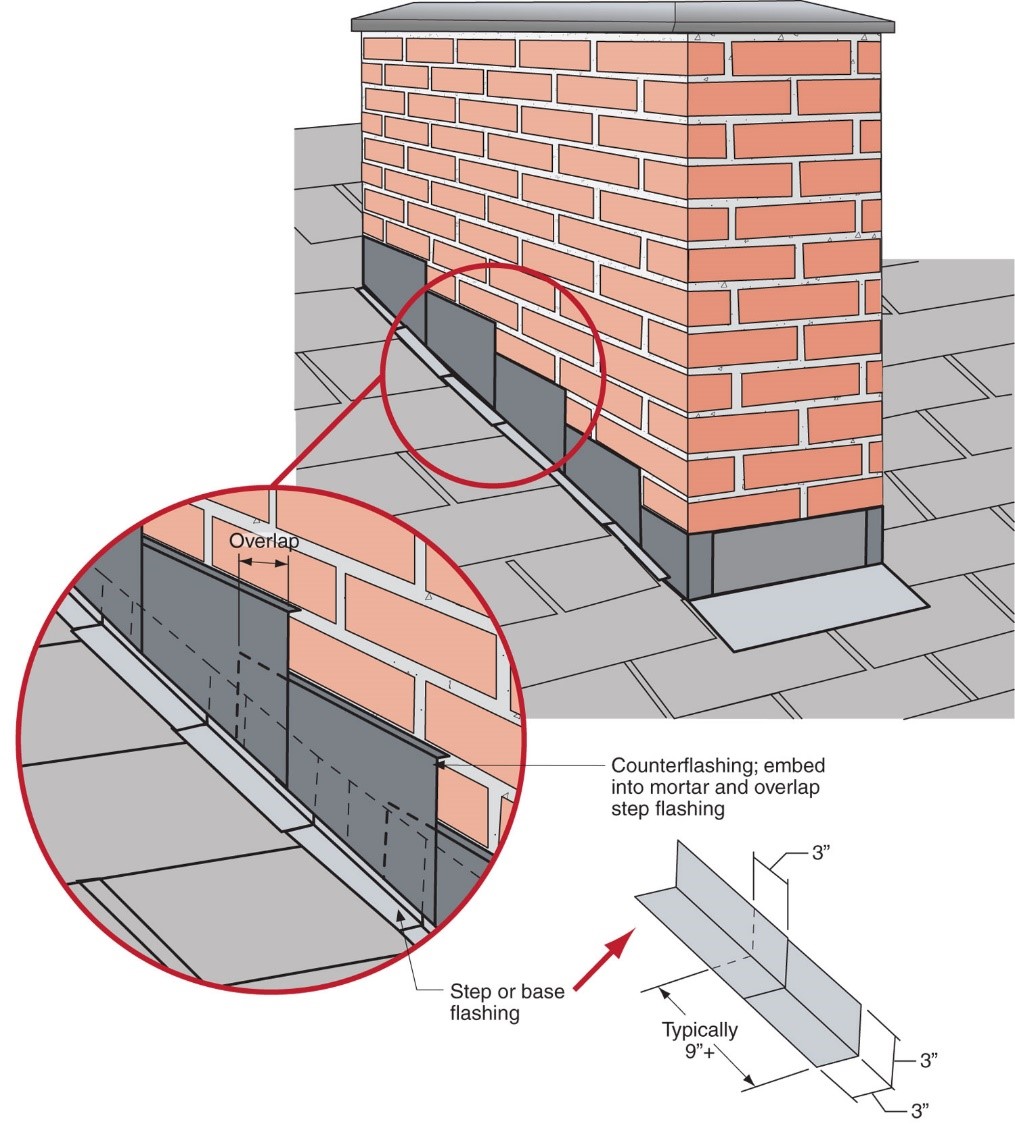
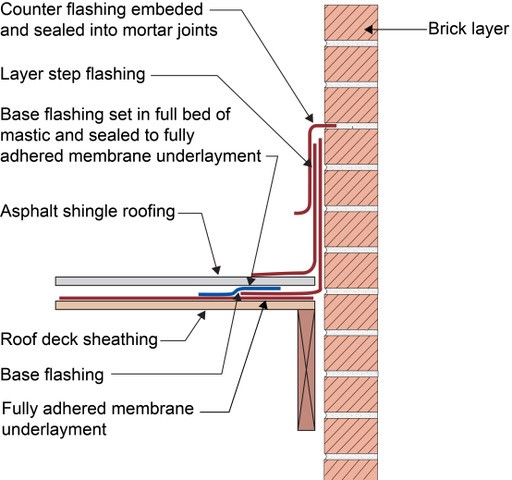
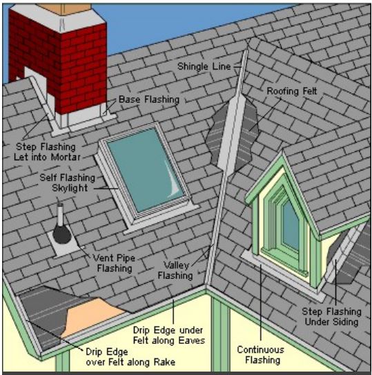
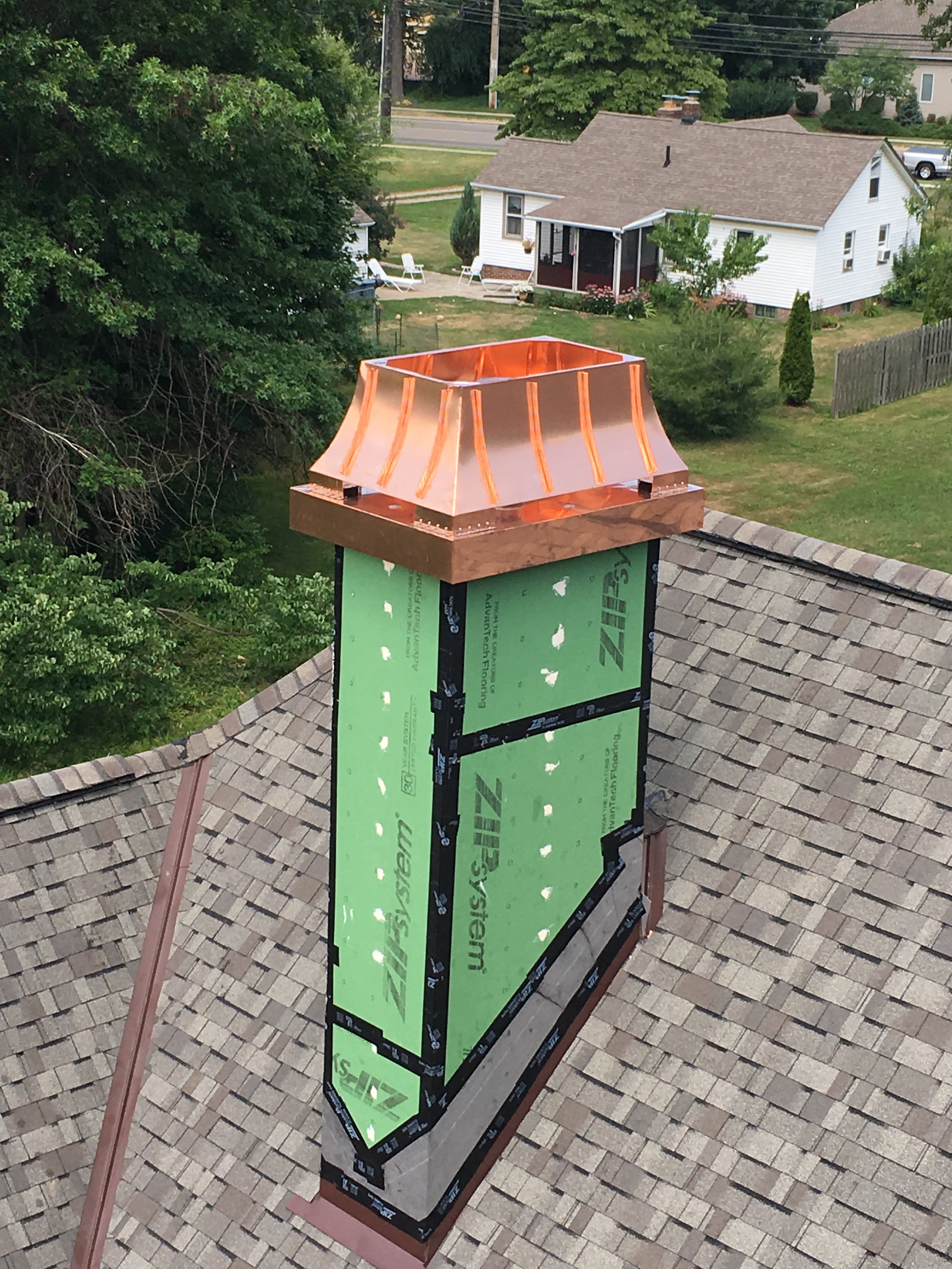
Metal flashing typically serves as a water control layer transition between the brick layer and the fully adhered roof membrane underlayment. The metal flashing consists of three elements – a base flashing, a step flashing, and a counterflashing.
The base flashing should be sealed with a full bed of mastic to the top surface of the fully adhered roof membrane underlayment. A step flashing is then integrated in a layered manner with the asphalt shingle roofing. Counterflashing is embedded into the mortar joints of the brick layer and overlaps the base flashing and the step flashing, completing the waterproofing transition connecting the brick layer to the fully adhered roof membrane underlayment (Figure 1 and Figure 2).
Source
If a fully adhered roof membrane is not installed over the entire surface area of the roof deck, alternative roof deck water control requirements are necessary to provide acceptable performance and acceptable risk in high wind zones. Alternative roof deck air sealing and water control requirements can be the IBHS Fortified Home Hurricane Technical Summary (2019).
If an alternative roof deck water control approach is used, the base flashing should be sealed to the alternative roof deck water control layer with a full bed of mastic and step flashing and counterflashing should be installed as described above and in the guide Step and Kickout Flashing.
Where sloping roofs intersect the upper vertical surface of the brick layer enclosing the chimney flue, a cricket or saddle flashing should be installed to redirect rainwater that is draining down the roof slope around the chimney (Figure 3).

Source
During an earthquake, chimneys are the part of the home most likely to experience damage. In the 1994 Northridge earthquake in Los Angeles, around 15,000 chimneys fell (SFGate 2014). Each of these failures can result in damage to the home, occupants, and the surrounding site. A simple preventative inspection can be taken to assess the risk of chimney failure.
Ensuring Success
The chimney must be adequately tied to the roof framing for structural support in high winds and earthquakes.
The fundamental principle of waterproofing the connection between the roof assembly and the chimney is to connect the water control layer of the roof assembly to the water control layer of the chimney.
Metal flashing typically serves as a water control layer transition between the brick layer and the fully adhered roof membrane underlayment. Metal flashing typically has three elements - a base flashing, a step flashing, and a counterflashing. The flashing elements need to be layered in a manner to shed and drain incident rainwater.
Where sloping roofs intersect the upper vertical surface of the brick layer enclosing the chimney flue, a cricket or saddle flashing should be installed to redirect rainwater that is draining down the roof slope around the chimney.
Install metal straps on existing masonry chimneys as reinforcement during earthquakes. If a professional engineer instead recommends retrofitting a chimney by capping, remodeling the chimney, or installing an entirely new firebox and chimney, follow their recommendations.
Region
Hurricane-Prone Areas
In its Fortified Home program, the Insurance Institute for Building and Home Safety (IBHS) requires that the chimney be adequately connected to the roof framing to prevent the chimney from collapsing or breaking away during high winds. See the CAD tab of this guide for a detail from IBHS that specifies a retrofit method for providing adequate anchorage of an existing chimney to the roof members. IBHS requires that if the chimney is more than 5 feet above the roof, support detailing must be specified by an engineer or licensed design professional. See the IBHS Fortified Home Hurricane Standards (2019) for additional details.
Waterproofing of the connection between the roof assembly and the chimney is also important for controlling rainwater entry during high wind events such as hurricanes. The fundamental principle of waterproofing the connection between the roof assembly and the chimney is to connect the water control layer of the roof assembly to the water control layer of the chimney.
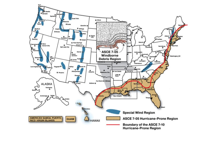
In high wind zones shown in Figure 1, a fully adhered roof membrane underlayment should be installed over the roof deck sheathing. This underlayment water control layer needs to be connected to the water control layer of the chimney. The water control layer of a chimney is most commonly the brick layer or other exterior cladding comprising the structural enclosure supporting the chimney flue.
Source
Report providing guidance on how to improve the wind resistance of existing residential buildings in Mississippi and across the Gulf Coast.
Earthquake-Prone Areas
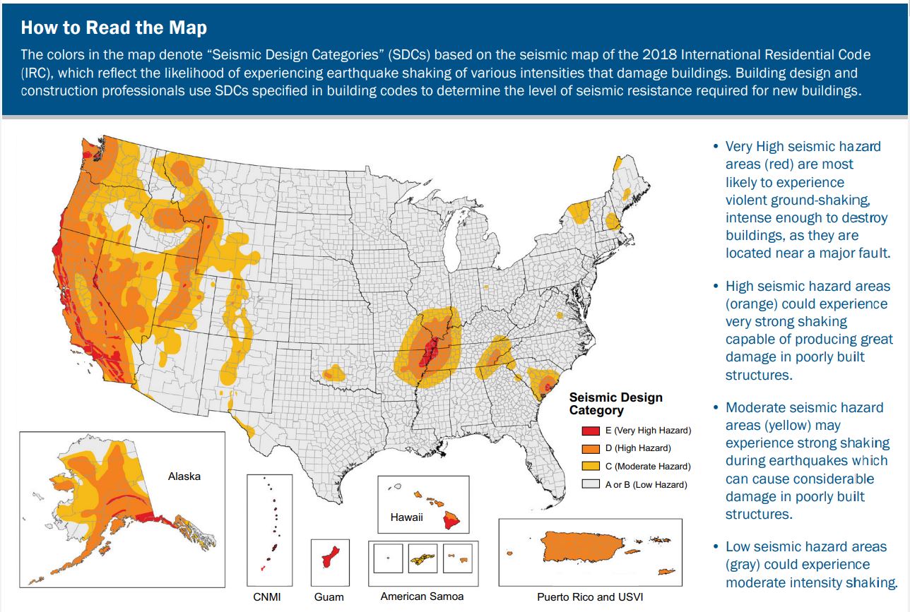
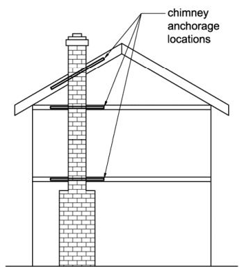
In areas at high risk of earthquakes, such as those shown in Figure 2 and in other areas where required by local building code, install metal strapping on existing masonry chimneys or retrofit the firebox, chimney, or both for seismic resistance.
Source
2018 edition of code for residential buildings that creates minimum regulations for one- and two-family dwellings of three stories or less, bringing together all building, plumbing, mechanical, fuel gas, energy and electrical provisions for one- and two-family residences.

Training
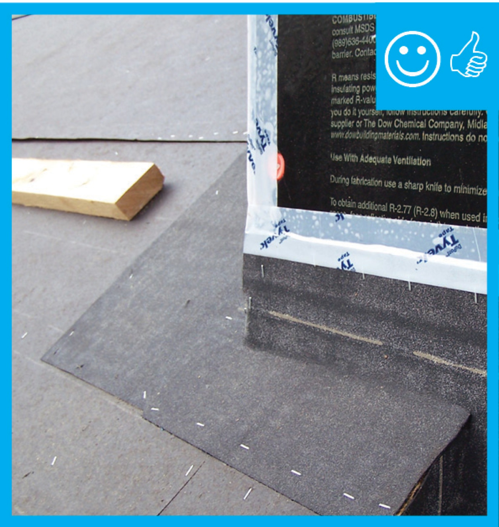
Right and Wrong Images
Source
Source
Fact sheet describing flashing of roof penetrations to make a home more resistant to high winds, hurricanes, and rainwater intrusion.
Source
Source
Guide describing details that serve as a visual reference for each of the line items in the Water Management System Builder Checklist.
Source
Fact sheet describing flashing of roof penetrations to make a home more resistant to high winds, hurricanes, and rainwater intrusion.
Source
Webpage from FEMA describing how to properly reconstruct masonry fireplace chimneys damages by earthquakes.
Source
Source
Report presenting seismic design and construction guidance for one- and two-family houses for homebuilders, knowledgeable homeowners, and other non-engineers.
Source
Document from IBHS explaining how to inspect homes for earthquake preparedness and retrofit solutions for homes that have suffered structural damage as a result of earthquakes.
Source
Report presenting seismic design and construction guidance for one- and two-family houses for homebuilders, knowledgeable homeowners, and other non-engineers.
Source
Report presenting seismic design and construction guidance for one- and two-family houses for homebuilders, knowledgeable homeowners, and other non-engineers.
Source
Webpage from FEMA describing how to properly reconstruct masonry fireplace chimneys damages by earthquakes.
Source
Webpage from FEMA describing how to properly reconstruct masonry fireplace chimneys damages by earthquakes.
Source
Videos


CAD Files
Compliance
Retrofit
In its Fortified Home program, the Insurance Institute for Building and Home Safety (IBHS) requires that the chimney be adequately connected to the roof framing to prevent the chimney from collapsing or breaking away during high winds and earthquakes. See the CAD tab of this guide for a detail from IBHS that specifies a retrofit method for providing adequate anchorage of an existing chimney to the roof members. IBHS requires that if the chimney is more than 5 feet above the roof, support detailing must be specified by an engineer or licensed design professional. See the IBHS Fortified Home Hurricane Standards (2019) for additional details.
Ensuring Chimneys are Adequately Anchored (The following is excerpted from FEMA P-804, 2010, Wind Retrofit Guide for Residential Buildings.)
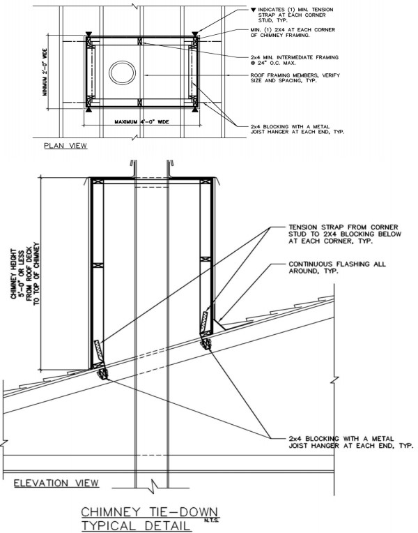
If a wood-frame chimney on a home collapses during a high-wind event, significant damage can occur to the home as well as surrounding buildings. Therefore, if a home undergoing a wind retrofit project has a chimney framed with wood, it should be anchored to the structure as part of the continuous load path retrofit so that loads applied to it are transmitted through the load path and adequately resisted. Wood-frame chimneys that are on the interior of the roof and extend 5 feet or less from the roof deck can be retrofitted using prescriptive requirements, described here.
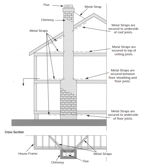
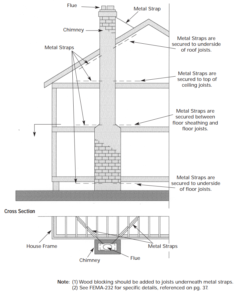
The following retrofits should be performed on wood-framed chimneys: 1. Tensions straps with a minimum tension capacity of 700lbs. at each end should be fastened to the stud at each corner of the chimney and to the roof framing members below the chimney. 2. Wood structural panels with a minimum nominal thickness of 7/16 inch should be applied to the chimney framing on all sides. 3. Continuous wood blocking supports should be fastened to roof framing members around the base perimeter of the chimney framing using joist hangers. Wood blocking should have minimum dimensions of 2 inches x 4 inches and should be continuous around the chimney framing.
For more information on this type of solution, consult retrofit programs such as the IBHS FEH program for prescriptive details. If the wood-frame chimney is on the interior of the roof, the entire chimney structure is supported by the roof framing members, which allows the use of the prescriptive solution described above. If the chimney is located along the roof edge, the chimney structure is supported by both roof framing members and a load-bearing wall on the exterior of the building, making a prescriptive retrofit more difficult. Similarly, larger chimneys may require a more detailed and less generic solution to adequately anchor the chimney to the structure. If a chimney extends farther than 5 feet above the roof deck or extends along the roof perimeter, a professional engineer should be consulted to develop a detailed solution. The solution should address the following:
- Chimney wall framing adequacy
- Overturning stability and base shear requirement
- Adequacy and bracing requirements for roof support members
- Attachment schedule of chimney structure to the roof structure.
A professional engineer will typically be required to complete the continuous load path retrofit portion of the Advanced Mitigation Package. An engineered solution may involve installing additional metal connectors at the roof level if the side wall framing members are continuous from the bearing wall framing. It may include altering the member size and spacing of roof framing members to support the load from the chimney, installing wood posts at each end of the wall if the chimney side wall framing members start from the top of the supporting wall, or setting posts at the interior side of the wall framing at each corner. A retrofit solution for a masonry chimney will be more difficult than for a wood-frame chimney, and would likely require rebuilding the chimney (at least for the portions above the roof line) (FEMA P-804, 2010).
Inspect the chimney to verify there is flashing where the chimney intersects with the roof. If flashing does not exist, install flashing as described in this guide, ensuring that it is properly connected to the connection between the roof assembly and the chimney is important for controlling rainwater entry during high wind events such as hurricanes. The fundamental principle of waterproofing the connection between the roof assembly and the chimney is to connect the water control layer of the roof assembly to the water control layer of the chimney. If the exterior cladding of the chimney is brick, step flashing, base flashing, and counter flashing should be installed as described in the Description tab.
In high wind zones, a fully adhered roof membrane underlayment should be installed over the roof deck sheathing. This underlayment water control layer needs to be connected to the water control layer of the chimney.
When retrofitting an earthquake-damaged chimney, start by changing the design from the pre-earthquake conditions that caused the failure. FEMA’s ‘Repair of Earthquake-Damaged Masonry Fireplace Chimneys’ describes four retrofit options intended to minimize the risk of future chimney problems. (FEMA 2015). Note that FEMA states it is generally considered infeasible to retrofit chimneys to meet up-to-date earthquake bracing requirements. (FEMA P-530, 2020). In cases in which a chimney retrofit is feasible, choose one of the four following retrofit options.
Repair of Earthquake-Damaged Masonry Fireplace Chimneys 2015
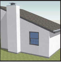
1. Good – Capping of Chimney at Roof Level (Alternative A)
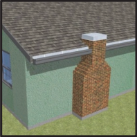
For a single-story dwelling, if all damage occurred at or above the roof level, the chimney can be permanently removed down to the roof level (Figure 1). This is only possible when use of the fireplace will be discontinued. This is the least costly of the alternatives, but also provides a lesser level of hazard mitigation.
Exterior appearance: The firebox and chimney will remain unchanged up to the roof level. The upper portion of the chimney will be removed.
Interior appearance: Fireplace and mantel will remain, but the fireplace can no longer be used and will need to be closed off.
Environmental: Fireplace can remain fuel-burning (note that the owner could also choose to convert to a more environmentally friendly gas-burning fireplace), although this option would require that a functioning flue be installed or retained through the original chimney.
Source
Webpage from FEMA describing how to properly reconstruct masonry fireplace chimneys damages by earthquakes.
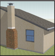
2. Better – Reconstruction from Top of Firebox, Maintaining Existing Fireplace (Alternative B)
Reconstruction can allow continued use of an undamaged masonry firebox in combination with a new metal flue and light-weight chimney enclosure (Figure 2).
Exterior appearance: The firebox at the bottom of the chimney will remain exposed brick. The reconstructed portion of the chimney is often finished with siding or stucco, but can also be finished with adhered brick veneer to preserve the original appearance.
Interior appearance: Remains unchanged.
Environmental: Fireplace can remain fuel-burning. (Note that the owner could also choose to convert to a more environmentally friendly gas-burning fireplace.)
Source
Webpage from FEMA describing how to properly reconstruct masonry fireplace chimneys damages by earthquakes.
3. Better – Reconstruction from Top of Firebox, Using Fireplace Insert (Alternative C)
Reconstruction of a masonry chimney allows continued use of an undamaged masonry firebox in combination with a new chimney. In addition, a factory‐built fireplace insert is installed inside of the fireplace (Figure 3).
Exterior appearance: The firebox at the bottom of the chimney will remain exposed brick. The reconstructed portion of the chimney is often finished with siding or stucco, but can also be finished with adhered brick veneer to preserve the original appearance.
Interior appearance: Fireplace and mantel will remain, but a fireplace insert will be visible inside of the original masonry fireplace.
Environmental: Fireplace can remain fuel‐burning. Fireplace inserts can be more energy efficient at producing heat in the home, can reduce emissions through more complete combustion of solid fuels, or can be converted to a more environmentally friendly gas‐burning fireplace.
Source
Webpage from FEMA describing how to properly reconstruct masonry fireplace chimneys damages by earthquakes.
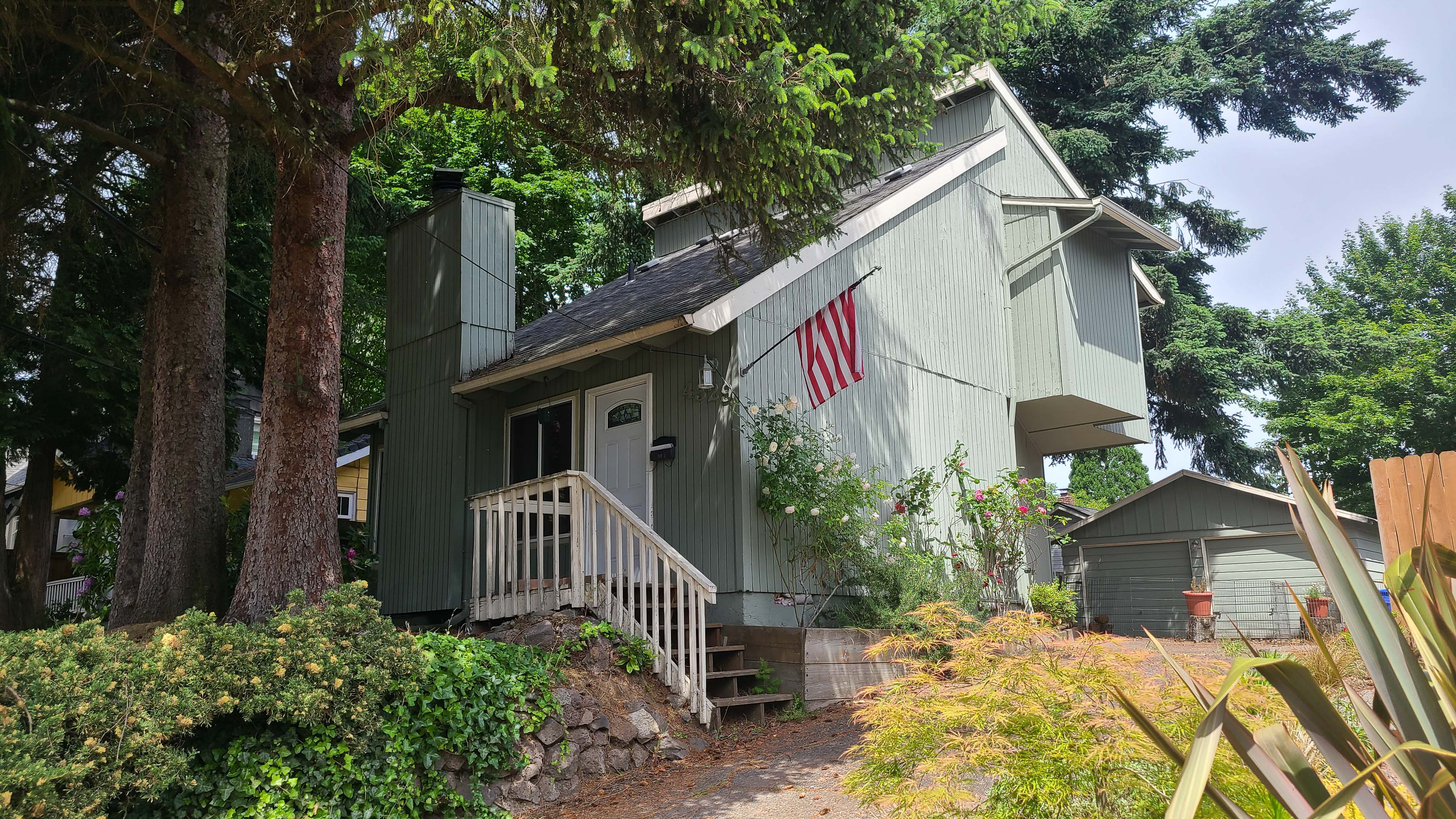
4. Best – Full Reconstruction of Firebox and Chimney (Alternative D)
Replacement of the entire firebox and chimney with light‐frame construction above the top of the foundation is necessary if earthquake damage extends below the shoulder of the firebox (Figure 4). It is also appropriate where complete removal of fireplace masonry is preferred.
Exterior appearance: The entire height of the firebox and chimney is reconstructed and is often finished with siding or stucco, but can also be finished with adhered brick veneer to preserve the original appearance. None of the original brick masonry remains.
Interior appearance: The fireplace and mantel will be removed and replaced with a factory‐built fireplace unit. This can provide an opportunity to change or modernize the interior appearance or enhance the use of the fireplace.
Environmental: The fireplace can remain fuel‐burning. Factory‐built fireplace units can be more energy efficient at producing heat in the home, can reduce emissions through more complete combustion of solid fuels, or can be more environmentally friendly gas‐burning fireplaces.
Source
Webpage from FEMA describing how to properly reconstruct masonry fireplace chimneys damages by earthquakes.
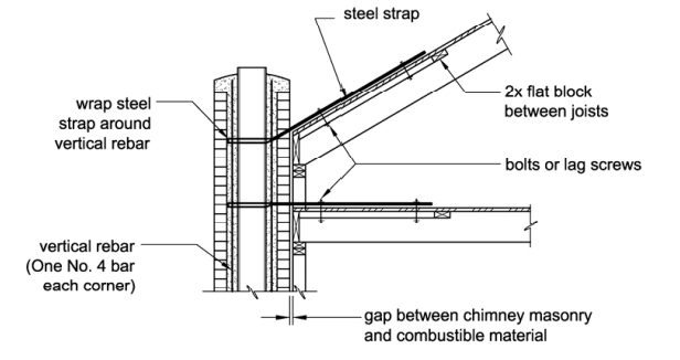
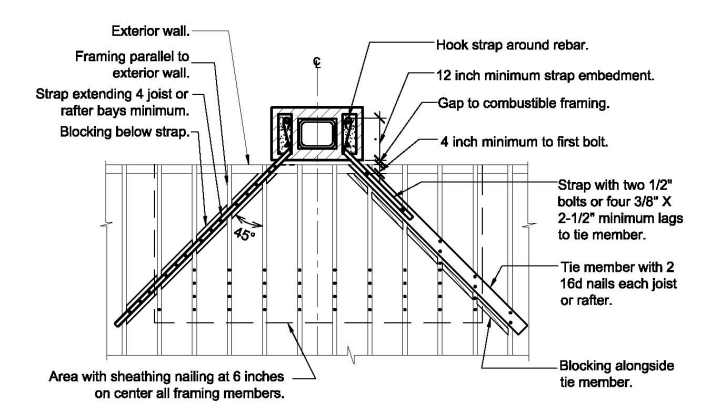
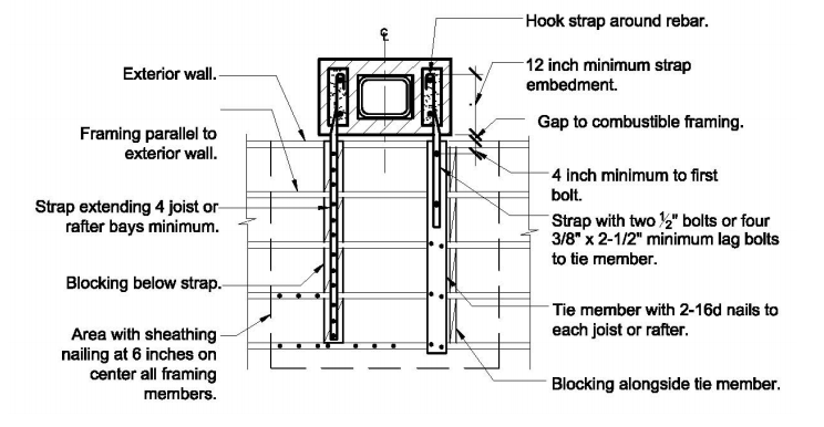
When examining a chimney structure for potential seismic problems, IBHS recommends checking for severe cracks, described as anything wider than the edge of a dime. These cracks usually occur in the area between the bricks in the mortar. Besides obvious problem areas such as cracks, other potential issues include chimneys that are tall and narrow that will sway and possibly fall or crack during an earthquake. Consider hiring a professional contractor who works on chimneys to shorten the chimney in cases where the structure is too tall. In some cases, chimneys are held to the side of the home using straps. If this is the case, inspect these fastenings for any evidence of rust on the fastenings or poor workmanship, such as large gaps between the fastenings and chimney structure. As with other roof structure components, if you are unsure of what to do, contact a professional engineer to add structural components such as bracing and metal strapping to anchor the chimney properly (IBHS 2001). IBHS recommends reinforcing masonry chimneys in earthquake zones with metal straps as shown in Figure 5 below.
Source
Document from IBHS explaining how to inspect homes for earthquake preparedness and retrofit solutions for homes that have suffered structural damage as a result of earthquakes.
California Earthquake Authority gives similar advice to homeowners. Their three reinforcement options are as follows:
- 1. Add layers of plywood to the roof around the chimney.
- 2. Remove the upper part of the chimney and replace it with metal.
- 3. Add a diagonal steel brace to the chimney.
The upfront cost of retrofitting a chimney to withstand an earthquake can be a barrier for homeowners. Table 1 illustrates that while the project cost of retrofitting a chimney as a preventative measure can be high depending on the specifics of the project, the cost of repairing earthquake damage caused by chimney failure is much higher (SCEC 2021).

Source
Webpage from Southern California Earthquake Center (SCEC) on identifying key problem spots on unreinforced masonry chimneys and how to retrofit them to withstand seismic forces.
More Info
References and Resources
*For non-dated media, such as websites, the date listed is the date accessed.
Contributors to this Guide
The following authors and organizations contributed to the content in this Guide.
Building Science Corporation
Questions? Comments? Contact our webmaster.