
Flashing of Roof-Wall Intersections in Existing Homes

    Scope
    Scope Images
    Image
    Existing wall-to-lower roof transition retrofitted with a new strip of fully adhered air control transition membrane, new step flashing, new roof underlayment, and new cladding
    Scope

    Install new step and kick-out flashing where an existing roof meets an existing wall as part of a roof replacement. It can also be done as a stand-alone retrofit measure or as an exterior wall upgrade. Install and properly integrate flashing at the intersection of an existing wall and roof, as follows:

    • Inspect the wall and roof framing to assess existing conditions and develop specific detailing for flashing the intersection of the wall and roof.
    • If there is no metal flashing installed at the wall-roof intersection, or if the existing flashing is damaged, improperly installed, or allowing water to damage the wall, remove the siding and any existing flashing to expose at least 8 inches of the wall. Repair any damaged sheathing and framing.
    • If the existing sidewall-roof intersection did not include a kick-out flashing, carefully inspect the side wall at the roof eave for possible deterioration from bulk water leakage and repair as needed.
    • Install a new adhesive membrane (ice and water protector) and metal step or continuous flashing that is properly integrated into the weather-resistant barrier and wall and roof coverings to provide continuous water, air, vapor, and thermal control layers on the walls and roof.

    For more on roof/wall connections, see the U.S. Department of Energy’s Standard Work Specifications.

    See the Compliance Tab for related codes and standards, requirements, and criteria to meet national programs such as DOE’s Zero Energy Ready Home programENERGY STAR Single-Family New Homes, and Indoor airPLUS.


    Description
    Description

    The fundamental principle of water management is to shed water by layering materials in such a way that water is directed down, out, and away from the building. The key to this fundamental principle is drainage. Drainage applies to assemblies such as walls, roofs, and foundations as well as transitions to those assemblies such as lower roofs, porch roofs, decks, balconies, railings, and dormers.
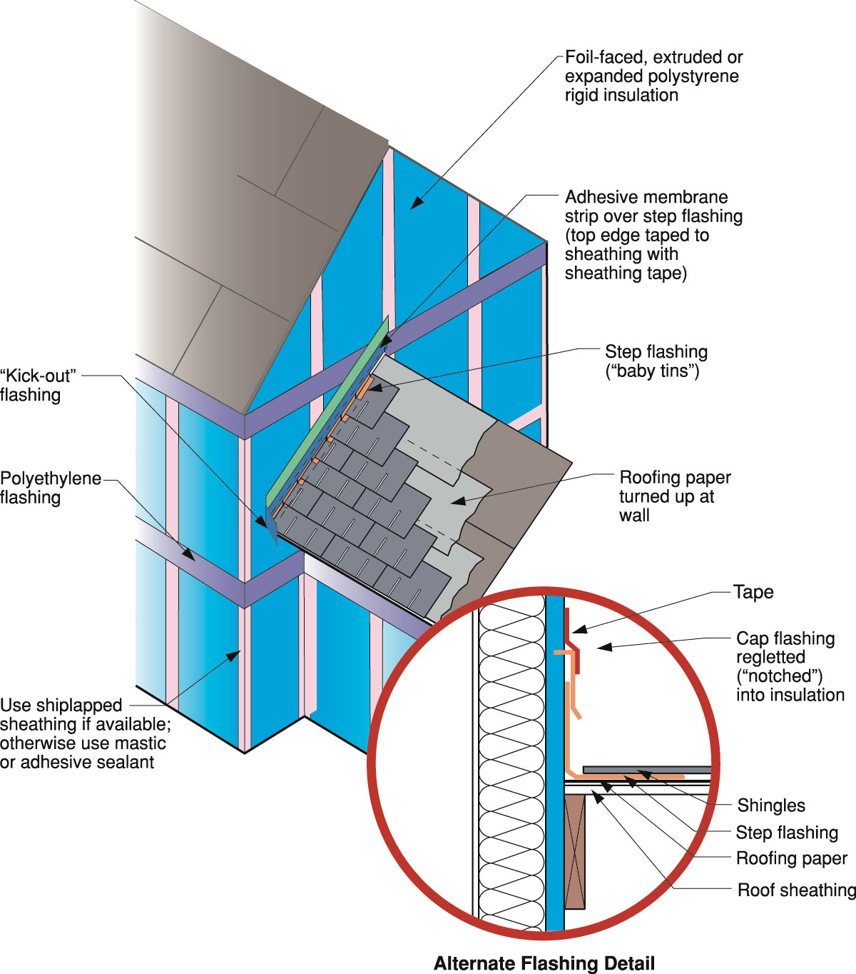
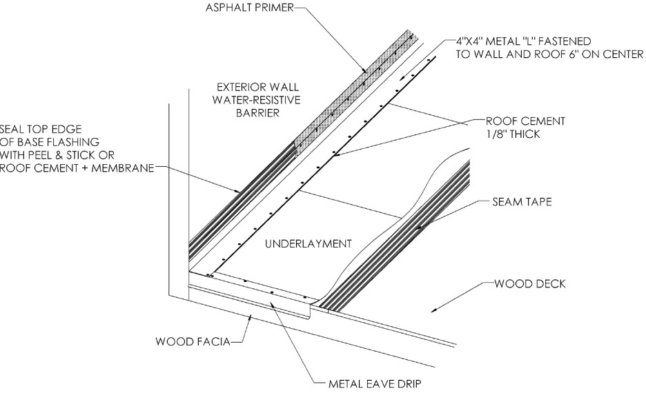
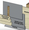
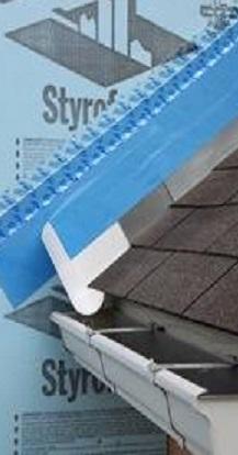
    The most elegant expression of the concept of drainage is flashing. Flashing is the most underrated of building enclosure components and arguably one of the most important. Metal flashing and self-adhesive flashing tapes protect vulnerable building components and help direct water down and out of the building (see Figure). Flashing should be integrated with roof and wall drainage planes, such as house wrap or building paper, in a shingle fashion where the top layer of the weather-resistant barrier (WRB) or flashing laps over the bottom layer to prevent water draining behind the bottom layer. These water control details are shown in Figures 4 and 5.

    The down and out approach to flashing – metal flashing directs water down and out of building assemblies.
    Figure 1. The down and out approach to flashing – metal flashing directs water down and out of building assemblies. (Source: Building Science Corporation.)


    When the roof covering is being replaced on an existing roof, new flashing should be installed at roof-wall intersections. This flashing may also be replaced as a stand-alone retrofit measure or as part of an exterior wall upgrade.

    Flashing is required at all roof-wall intersections. Either continuous L-metal flashing or step flashing is used to prevent water intrusion into the wall where a sloped roof intersects a vertical wall. Step flashing is used with shingle roofs; continuous flashing is used with metal and rubber membrane roofs.

    The metal flashing pieces are bent at a right angle, with half of the flashing against the wall and the other half interwoven with or underneath the shingles of the abutting roof. The upturned leg of the step flashing is behind the vertical drainage plane (house wrap) on the wall or sealed to it with an adhesive membrane and sheathing tape. Metal flashing must be corrosion-resistant and at least 0.19 inches thick (2018 IRC Section R903.2.1). For asphalt shingle roofs, the IRC requires the base flashing against the vertical sidewall to be continuous or step flashing that is at least 4 inches high against the wall and 4 inches wide above the roofing underlayment (2018 IRC Section R905.2.8.3). Note that step flashing is typically pre-formed individual metal pieces with 5-inch legs (5 inches high by 5 inches wide) and 7 inches long (referred to as 5 by 7 step flashing or base flashing). For metal or rubber membrane roofs, continuous flashing is an alternative to step flashing. The self-adhesive membrane should consist of a material like a butyl or acrylic (meeting AAMA 711). Refer to the manufacturer’s details for installation. See IRC 2018 for the testing requirements for all the materials used. (IRC 2018 Section R903.2 Flashing, Section R905.2.8.3 Sidewall flashing, R908.6 Flashings for reroofing).

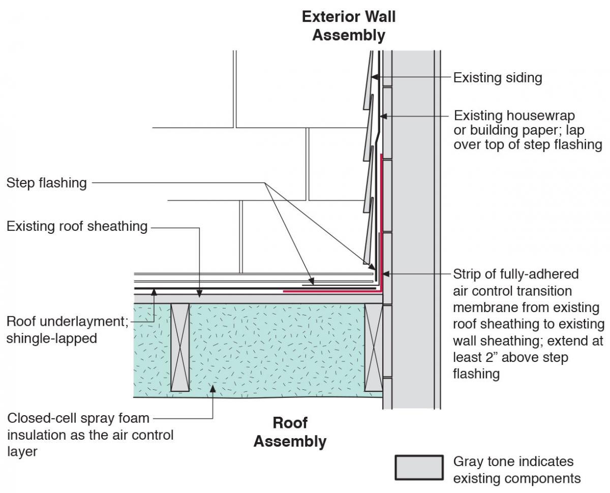
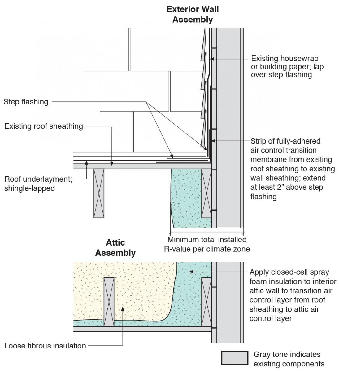
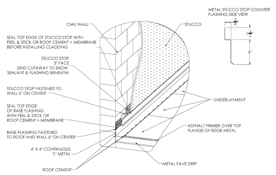
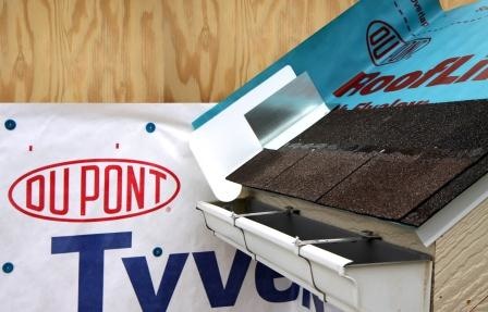
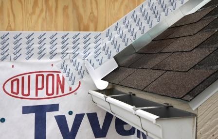
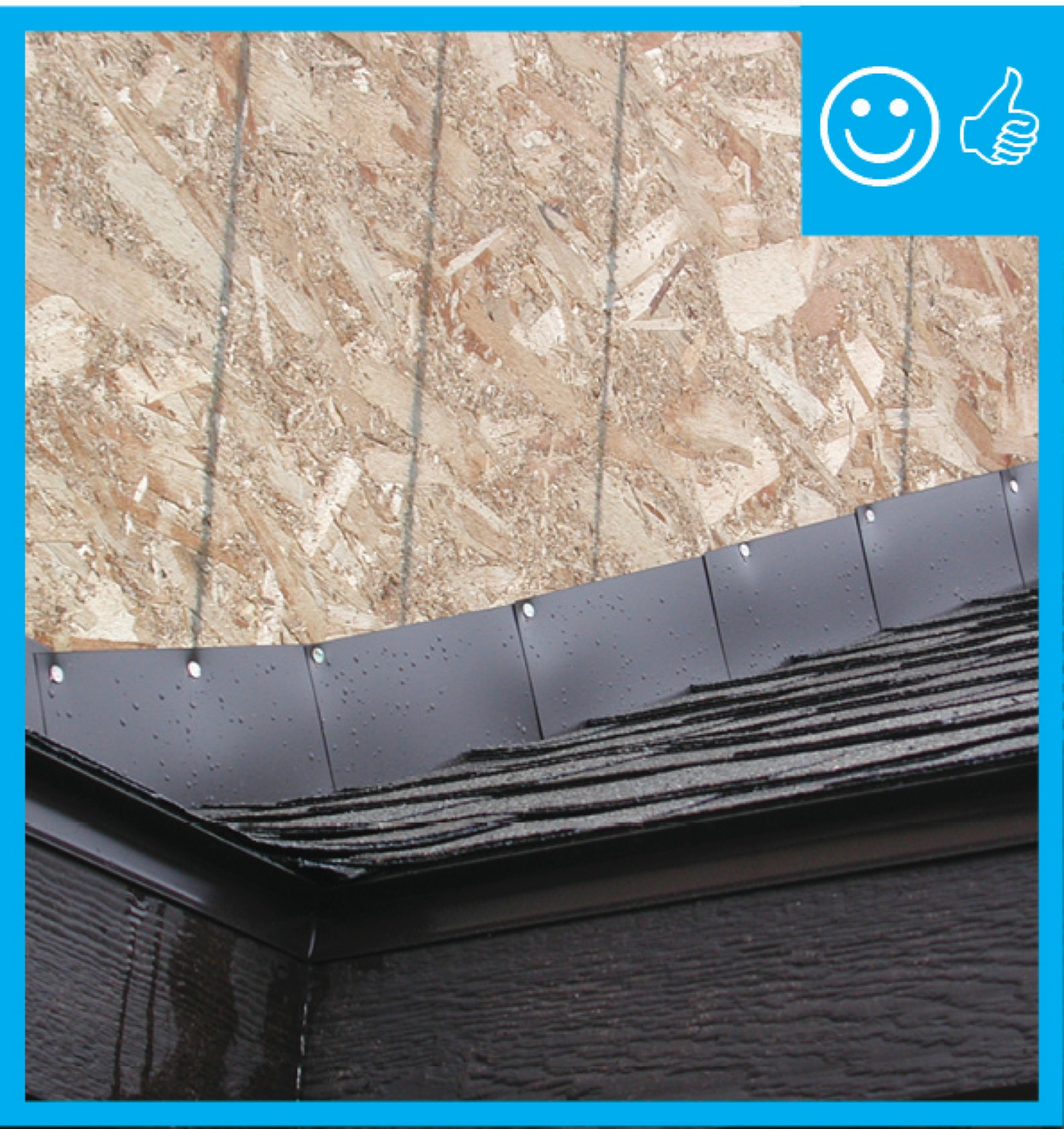
    Figures 2 and 3 show a front view of the integration of a new strip of fully adhered air control transition membrane, new step or continuous flashing, new roof underlayment, and new cladding with the existing house wrap and siding. Figure 4 shows continuous L-metal flashing integrated with underlayment at roof-wall intersections. Figure 5 shows flashing at a roof-wall intersection with a CMU wall. Note Figures 4 and 5 are from the Insurance Institute for Building and Home Safety (IBHS) Fortified Home program, which recommends that the metal drip edge be installed over the underlayment on roofs in hurricane and high-wind-prone regions. This is not consistent with shingle-fashion installation of roofing materials generally recommended as a good practice; however, IBHS reports that they have tested this with good results. Counter flashing could be installed to reduce disruption to the flow of rainwater off the roof here. Figures 6 through 11 show the installation of the step and kick-out flashing on a new home but many of the steps are similar.

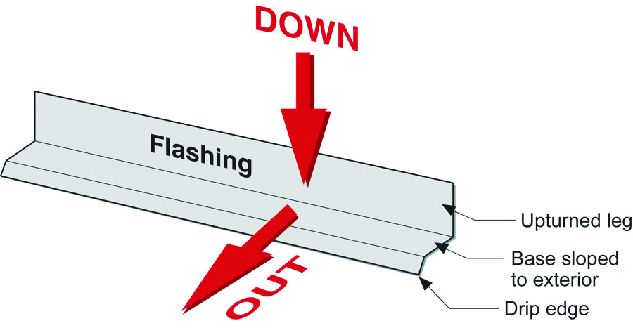
    Installation of kick-out flashing is a critical component of a step or continuous flashing. Kick-out flashing is a piece of flashing at the bottom of a section of the roof that adjoins a wall. It is installed to direct water runoff away from the adjoining wall and usually into a gutter. Kick-out flashing is sometimes fabricated on-site by the roofing contractor; however, seamless plastic flashing pieces specifically molded to serve as kick-out flashing pieces are available. These are sized to handle the larger volumes of water runoff that may be concentrated along the wall in rain storms. For more information, see the guide Step and Kick-out Flashing at Roof-Wall Intersec

    Existing wall-to-lower roof transition with a new strip of fully adhered air control transition membrane, new step flashing, new roof underlayment, and new cladding – view from eave.
    Figure 2. Existing wall-to-lower roof transition with a new strip of fully adhered air control transition membrane, new step flashing, new roof underlayment, and new cladding – view from eave. Closed-cell spray foam is installed at the underside of the lower roof deck as an air control layer. (Source: Building Science Corporation 2013.)


    Existing wall-to-lower roof with attic transition with a new strip of fully adhered air control transition membrane, new step flashing, new roof underlayment, and new cladding – view from eave.
    Figure 3. Existing wall-to-lower roof with attic transition with a new strip of fully adhered air control transition membrane, new step flashing, new roof underlayment, and new cladding – view from eave. Closed-cell spray foam is installed at the interior attic wall to transition the air control layer from the roof sheathing to the attic air control layer. (Source: Building Science Corporation 2013.)


    Continuous L-metal flashing integrated with underlayment at roof-wall intersections.
    Figure 4. Continuous L-metal flashing integrated with underlayment at roof-wall intersections. (Source: IBHS 2019.)


    Flashing at roof-wall intersection with CMU wall.
    Figure 5. Flashing at roof-wall intersection with CMU wall. (Source: IBHS 2019.)


    How to Install Flashing at the Transition of a Wall to a Lower Roof

    1. Remove roofing and enough siding on the wall above the roof-wall intersection to expose the existing house wrap or building paper.
    2. Inspect the structural integrity of the wall and the overhang. Check the framing for any deficiencies, rot, insect damage, etc. Proceed only after needed repairs are performed. Based on the findings, revise the wall and overhang assembly and review specific detailing as needed. Follow the minimum requirements of the current adopted local building code.
    3. Install a fully adhered air control transition membrane from the existing roof sheathing onto the face of the existing wall sheathing (Figure 6). Extend at least 2 inches above the future step flashing.
    4. Install the roof underlayment as the water control layer. Extend it to the existing wall and over the transition membrane; the underlayment should wrap up the sidewall at least 8 inches.
    5. Install new kick-out and step flashing, integrated with shingles as required (Figures 7, 8, 9). Best practice is to install counter flashing, using a self-adhered membrane, over the top edge of the step flashing (Figure 10). Integrate the vertical leg of the step flashing, and counter flashing, with the weather-resistive barrier of the wall. See the guide Step and Kick-out Flashing at Roof-Wall Intersections. Install the new shingles and step flashing over the roof underlayment.
    6. Lap the existing house wrap or building paper over the top of the step flashing (Figure 11).
    7. Re-install the siding over the house wrap or building paper. Ensure a minimum 1.5-inch reveal between the bottom of the siding and the shingles of the roof.
    Apply roof underlayment over roof deck and up the sidewall over house wrap.
    Figure 6. Apply roof underlayment over roof deck and up the sidewall over house wrap. (Source: Dryflekt 2010.)


    Install shingle starter strip then kick-out diverter; attach to roof deck but not sidewall wrap.
    Figure 7. Install shingle starter strip then kick-out diverter; attach to roof deck but not sidewall wrap. (Source: Dryflekt 2010.)


    Place first shingle and next section of sidewall flashing over upper edge of diverter wrap.
    Figure 8. Place first shingle and next section of sidewall flashing over upper edge of diverter wrap. (Source: Dryflekt 2010.)


    Install remaining sidewall flashing, counter flashing, and shingles wrap.
    Figure 9. Install remaining sidewall flashing, counter flashing, and shingles wrap. (Source: Dryflekt 2010.)


    Apply self-adhesive flashing over top edge of the wall flashing, diverter, and house wrap.
    Figure 10. Apply self-adhesive flashing over top edge of the wall flashing, diverter, and house wrap. (Source: Dryflekt 2010.)


    Install the house wrap. Cut house wrap to fit over diverter and tape top of cut wrap.
    Figure 11. Install the house wrap. Cut house wrap to fit over diverter and tape top of cut wrap. (Source: Dryflekt 2010.)


    Success
    Ensuring Success

    Inspect the existing wall and overhang framing and review specific detailing for any deficiencies or water intrusion damage and make any corrections, if necessary.

    Ensure the water control layer of the roof and wall assemblies is continuous.

    Ensure proper lapping of building layers to shed water away from the wall and overhang assemblies.

    Terminate the step flashing with a weather-lapped kick-out flashing.

    Climate
    Climate

    Water Management

    The IRC does not have additional requirements for roof-wall flashing in hurricane-prone regions or other high-wind areas. Some local jurisdictions may have additional requirements or require specific product approval. Building codes establish minimum requirements, but products must also be installed in accordance with the manufacturer’s instructions. This is important because codes typically do not provide all the detailed information for a durable installation. Assessments by FEMA after hurricanes commonly find that water intrusion and structural building failures are due to improper installation of building components. So, even where the IRC does not require additional measures, proper installation is more critical in hurricane-prone regions.   

    While typically, all water-protecting components on a roof should be installed shingle fashion, IBHS Fortified does recommend in hurricane and high-wind regions that the drip edge at the roof eaves be installed over, not under, the drip edge.

    Cold Climates

    In cold climates (zones five and higher), install self-adhered ice and water shield membrane over the roof sheathing at the eaves from the edge of the roof line to at least 2 feet up the roof deck from the interior plane of the exterior wall. (See the guide Heavy Membranes at Eaves in Cold Climates.)

    The map in Figure 1 shows the climate zones for states that have adopted energy codes equivalent to the International Energy Conservation Code (IECC) 2009, 12, 15, and 18. The map in Figure 2 shows the climate zones for states that have adopted energy codes equivalent to the IECC 2021. Climate zone-specific requirements specified in the IECC are shown in the Compliance Tab of this guide. 


    Figure 1. Climate Zone Map from IECC 2009, 12, 15, and 18.
    Figure 1. Climate Zone Map from IECC 2009, 12, 15, and 18. (Source: 2012 IECC)


    Climate Zone Map from IECC 2021.
    Figure 2. Climate Zone Map from IECC 2021. (Source: 2021 IECC)


    Training
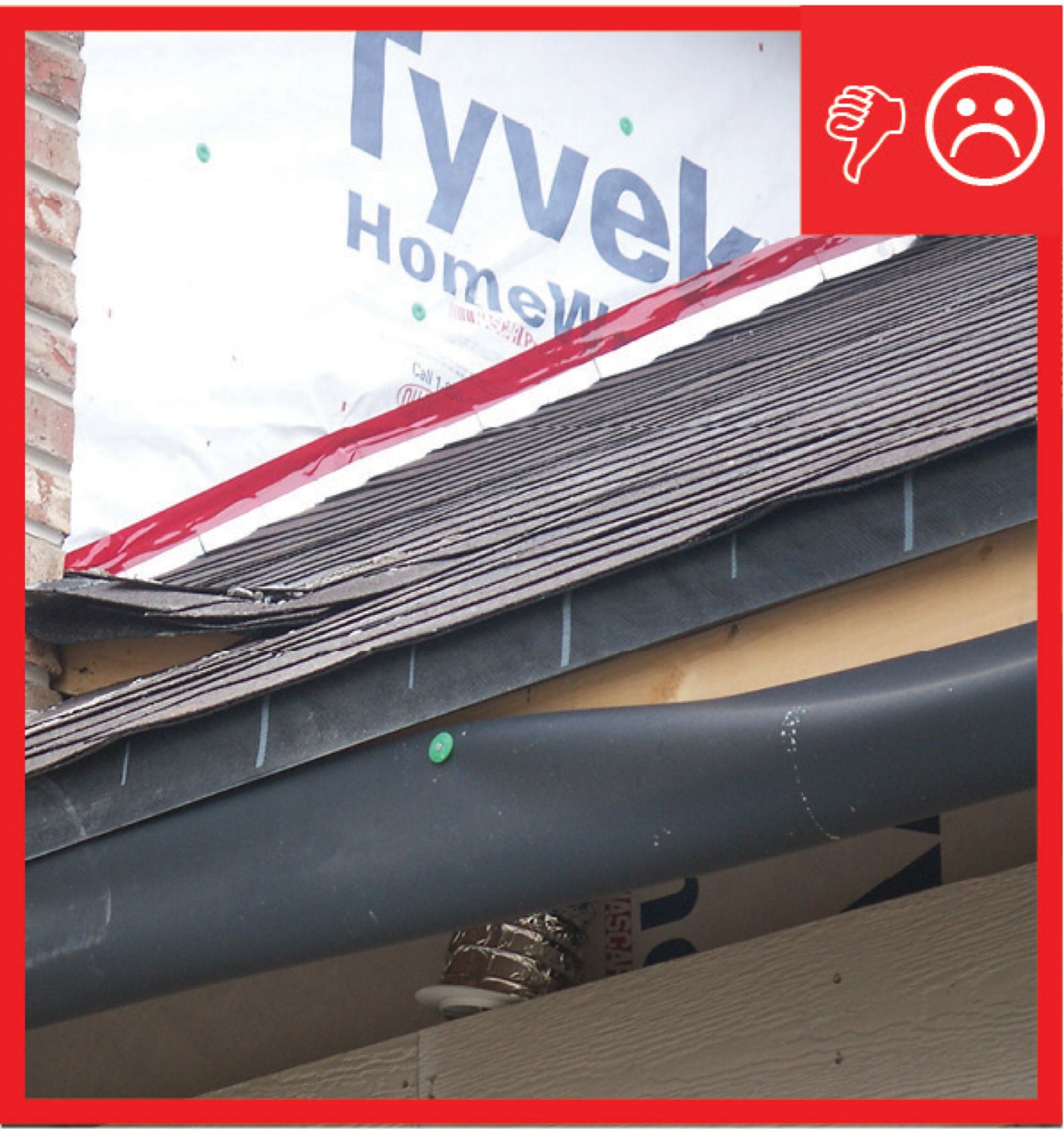
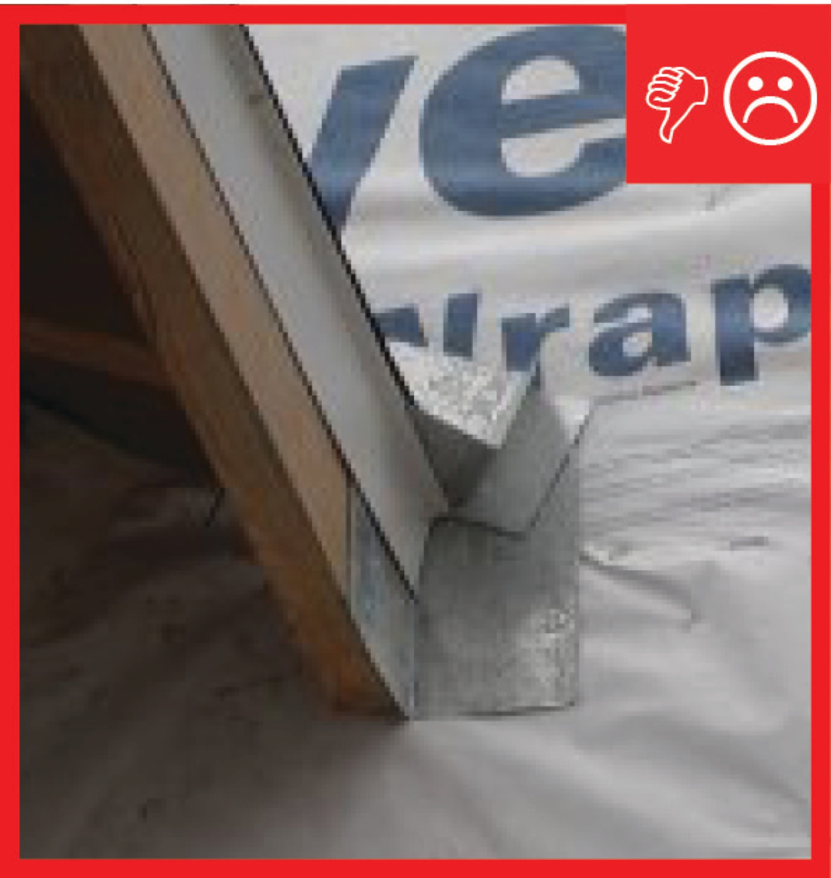
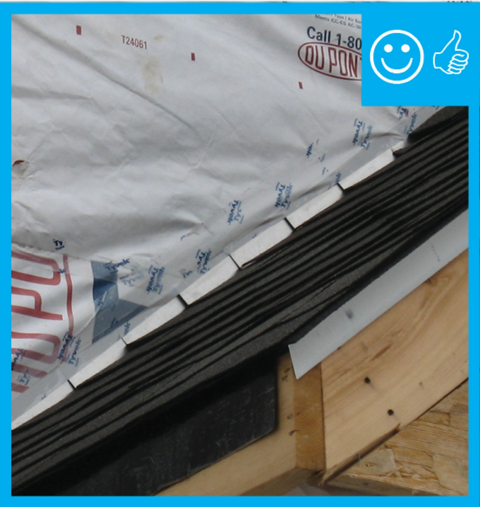
    Right and Wrong Images
    Image
    Right – The step flashing is the correct height above the roof deck
    Right – The step flashing is the correct height above the roof deck
    Image
    Wrong – The step flashing is not the required height above the roof deck
    Wrong – The step flashing is not the required height above the roof deck
    Image
    Wrong – the water-resistant barrier is layered underneath the step flashing, which could allow water to get behind the step flashing and into the wall.
    Wrong – the water-resistant barrier is layered underneath the step flashing, which could allow water to get behind the step flashing and into the wall.
    Image
    Right – The water-resistant barrier is layered over the step flashing to provide a complete drainage system
    Right – The water-resistant barrier is layered over the step flashing to provide a complete drainage system
    Videos
    Publication Date
    Author(s)
    Weather Proofing America
    Organization(s)
    Weather Proofing America
    Description
    Video explaining how to correctly install wall-to-roof flashing and kick-out flashing to protect walls from rain water damage.
    Publication Date
    Author(s)
    Guertin Mike
    Organization(s)
    Fine Homebuilding Magazine
    Description
    When flashing one of a house’s biggest potential leaks — where the eave overhang meets a vertical wall — editorial advisor Mike Guertin chooses to err on the side of caution to control water flow and not rely solely on step flashing.
    Compliance

    Compliance

    The Compliance tab contains both program and code information. Code language is excerpted and summarized below. For exact code language, refer to the applicable code, which may require purchase from the publisher. While we continually update our database, links may have changed since posting. Please contact our webmaster if you find broken links.

    ENERGY STAR Single-Family New Homes, Version 3/3.1 (Rev. 11)

    National Water Management System Builder Requirements

    3. Water-Managed Roof Assembly.

    3.1 Step and kick-out flashing at all roof-wall intersections, extending ≥ 4" on wall surface above the roof deck and integrated shingle-style with drainage plane above; boot/collar flashing at all roof penetrations.13

    3.2 For homes that don't have a slab-on-grade foundation and do have expansive or collapsible soils, gutters & downspouts provided that empty to lateral piping that discharges water on sloping final grade ≥ 5 ft. from the foundation or to underground catchment system not connected to the foundation drain system that discharges water ≥ 10 ft. from the foundation. Alternatives & exemptions in Footnote.4, 14, 15

    3.3 Self-adhering polymer-modified bituminous membrane at all valleys & roof deck penetrations.4, 16

    3.4 In 2009, IECC Climate Zones 5 & higher, self-adhering polymer-modified bituminous membrane over sheathing at eaves from the edge of the roof line to > 2 ft. up roof deck from the interior plane of the exterior wall.4, 16

    Footnote 4) Not required in Dry (B) climates as shown in 2009 IECC Figure 301.1 and Table 301.1.

    Footnote 13) Intersecting wall siding shall terminate one in. above the roof or higher, per manufacturer's recommendations. Continuous flashing shall be installed instead of step flashing for metal and rubber membrane roofs.

    Footnote 14). The assessment of whether the soil is expansive or collapsible shall be completed by a certified hydrologist, soil scientist, or engineer.

    Footnote 15) Any of the following are permitted to be used as alternatives to Item 3.2: a) a roof design that deposits rainwater to a grade-level rock bed with a waterproof liner and a lateral drain pipe that meets discharge requirements per Item 3.2; b) a rainwater harvesting system that drains overflow to meet discharge requirements per Item 3.2; or c) a continuous rubber membrane (e.g., EPDM) that is aligned with the foundation wall from final grade to ≥ 8 in. below grade and then slopes ≥ 0.5 in. per ft. away from home for at least five ft., with Group I Soils (as defined in Footnote 9) covering the membrane to within three in. of the final grade.

    Footnote 16) As an alternative, any applicable option in 2009 IRC Section R905.2.8.2 is permitted to be used to meet Item 3.3, and any option in 2009 IRC Section R905.2.7.1 is permitted to be used to meet Item 3.4. EPA recommends but does not require, that products meet ASTM D1970. In addition, any option in 2009 IRC Section R905.13 is permitted to be used to meet either Item 3.3 or 3.4.

    Please see the ENERGY STAR Single-Family New Homes Implementation Timeline for the program version and revision currently applicable in your state.


    2009201220152018, and 2021 International Residential Code (IRC)

    Section R703.8 (R703.8.5 in 2015, 2018, and 2021 IRC) Flashing. Flashings shall be installed in a manner that prevents moisture from entering the wall and roof through joints in copings, through moisture-permeable materials, and at intersections with parapet walls and other penetrations through the roof plane.

    Section R903.2.1 Locations. Flashings shall be installed at wall and roof intersections, wherever there is a change in roof slope or direction, and around roof openings. Flashing shall be installed to divert the water away from where the eave of a sloped roof intersects a vertical sidewall. Where flashing is of metal, the metal shall be corrosion resistant with a thickness of not less than 0.019 inches (0.5 mm) (No. 26 galvanized sheet)

    Section R905.2.8.3 Sidewall flashing. Base flashing against a vertical sidewall shall be continuous or step flashing and shall be not less than 4 inches (102 mm) in height and 4 inches (102 mm) in width and shall direct water away from the vertical sidewall onto the roof or into the gutter. Where the siding is provided on the vertical sidewall, the vertical leg of the flashing shall be continuous under the siding. Where anchored masonry veneer is provided on the vertical sidewall, the base flashing shall be provided in accordance with this section, and counterflashing shall be provided in accordance with Section R703.8.2.2. Where exterior plaster or adhered masonry veneer is provided on the vertical sidewall, the base flashing shall be provided in accordance with this section and Section R703.6.3

    Section R907.6 (R908.6 in 2015, 2018, and 2021 IRC) Flashings. Flashings shall be reconstructed in accordance with the approved manufacturer's installation instructions. Metal flashing to which bituminous materials are to adhere shall be primed prior to installation.

    Retrofit: 2009201220152018, and 2021 IRC

    Section R102.7.1 Additions, alterations, or repairs. Additions, alterations, renovations, or repairs shall conform to the provisions of this code without requiring the unaltered portions of the existing building to comply with the requirements of this code unless otherwise stated. (See code for additional requirements and exceptions.)

    Appendix J regulates the repair, renovation, alteration, and reconstruction of existing buildings and is intended to encourage their continued safe use.

    More

    More Info.

    Access to some references may require purchase from the publisher. While we continually update our database, links may have changed since posting. Please contact our webmaster if you find broken links.

    References and Resources*
    Author(s)
    Pettit,
    Neuhauser,
    Gates
    Organization(s)
    Building Science Corporation,
    BSC
    Publication Date
    Description
    Guidebook providing useful examples of high performance retrofit techniques for the building enclosure of wood frame residential construction in a cold and somewhat wet climate.
    Author(s)
    Lstiburek
    Organization(s)
    Building Science Corporation
    Publication Date
    Description
    Book presenting the best techniques for energy and resource efficient residential construction in the colder climates of North America.
    Author(s)
    Building Science Corporation
    Organization(s)
    BSC
    Publication Date
    Description
    Brochure providing information about flashing.
    *For non-dated media, such as websites, the date listed is the date accessed.
    Contributors to this Guide

    The following authors and organizations contributed to the content in this Guide.

    Sales
    Building Science Measures
    Building Science-to-Sales Translator

    Kick-Out Flashing, Step Flashing = Roof-Wall Water Deflector

    Image(s)
    Technical Description

    Where roofs intersect walls is a critical point for flashing to prevent water leaks and damage. While wood siding may quickly show evidence of this water intrusion with peeling paint or staining, some wall claddings like fiber cement, vinyl siding, and brick veneer can mask the evidence for years. Roof step flashing must be effectively integrated with diverters known as kick-out flashing to effectively direct water to the gutters and avoid water damage.

    Roof-Wall Water Deflector
    Sales Message

    Roof-wall water deflectors help drain water away from high-risk corners where walls meet roofs. What this means to you is peace-of-mind knowing your home has a comprehensive set of measures that minimize the risk of water damage in your home. Wouldn’t you agree every home should have full water protection?

    Last Updated

    Mobile Field Kit

    The Building America Field Kit allows you to save items to your profile for review or use on-site.

    Sign Up  or  Log In

    Did you find this information helpful?

    If you have questions and/or would like a reply to this feedback, please include your e-mail address in the message.
    This question is for testing whether or not you are a human visitor and to prevent automated spam submissions.