


In existing homes, homeowners may sometimes experience strong drafts, temperature differences between rooms, poor air circulation, or central forced air systems that seemed to be noisier or working harder than they need to. One cause of these problems could be pressure differences between rooms. Pressure testing as part of a whole-house energy assessment can determine whether the house is pressures are unbalanced. An unbalanced, ducted HVAC system can result in wasted energy and poor thermal control.
Once ductwork is installed and trapped behind drywall and other finishes, it is very difficult to make changes. Here are a few upgrades that can improve circulation and air distribution coverage, allowing the system to operate closer to design for better performance and efficiency.
Sometimes poor circulation is due to the lack of a properly sized (low pressure) return air path back to the air handler.
- Check to make sure that furniture or storage is not blocking the return air grille if it is located low on a wall.
- Confirm the grille is sized properly per ACCA Manual D.
- If the return grille and duct are too small, check to see if they can be enlarged.
- If it’s not possible to enlarge the return path, see if there is an alternate route to add a second return path.
- If the return path is a transfer through a wall, ceiling, or floor to a mechanical room (often referred to as a “wild” return), increase the grille size, but be sure to supply a Z-duct, a 90-degree collar, or at least a baffle to reduce noise.
- Check that all bedrooms have either adequate door undercuts to allow equalization when rooms are closed or have a transfer grille installed through a wall or a jump duct installed above the ceiling to allow circulation back to the public space and then to the central air handler.
Sometimes the problem is a poorly balanced supply air system.
- Ideally, each supply branch duct should already have a manual balancing damper, typically located at the supply trunk take-off, to adjust airflow to each room. If so, incrementally adjust the dampers to reduce airflow to the comfortable rooms and thereby increase airflow to the uncomfortable room(s).
- Alternatively, manual balancing dampers in supply trunk ducts provide air balance control to different areas or zones of the house (rather than individual rooms). This is a common solution for two-story houses where one trunk serves the first floor and another trunk serves the second floor. These trunk dampers also allow seasonal adjustment; for instance, to deliver less air upstairs during the heating season and more air upstairs during the cooling season.
- If supply branch dampers are not installed or accessible (e.g., due to a finished basement ceiling or ducts installed within floors) minor air balance adjustments can be made by strategically opening and closing the dampers within the ceiling/floor supply registers. Note that this approach can result in unacceptable noise at the registers (e.g., whistling) due to increased air velocity.
- Caution: balancing dampers and register controls are intended to fine-tune airflows but are not intended to correct significant duct sizing errors. Too many closed dampers can lead to inadequate airflow through the furnace/air handler and result in HVAC equipment malfunction; this is most critical during cooling season since it can ice up the evaporator.
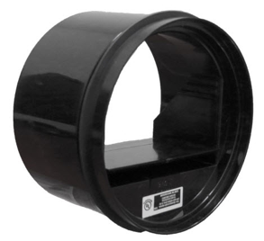
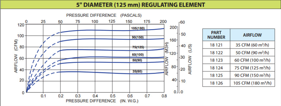
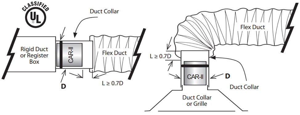
Where manual dampers are inaccessible or missing, consider installing passive airflow regulation devices (Figure 1). These dampers use an airfoil that self-adjusts to deliver no more than the maximum design flow, regardless of pressure variations (Figure 2). If the total flow of a system is proportionally controlled with an appropriately sized regulator in the neck of each register, the system will remain balanced within the range of pressures for which the regulators are specified. The retrofit can be accomplished from within the room by removing the grille of the register and installing the cartridge in the neck of the diffuser (Figure 3). Follow manufacturer’s sizing and installation instructions.
If multiple seasonal, weekly, and daily balancing schemes are required due to large variations in occupancy and use, a properly designed automatic zone control system (electronically controlled balancing dampers with a dedicated thermostat for each independent zone) may be desirable to improve occupant comfort (see ACCA Manual Zr for design guidance).
For more information, see the following guides:
More Info
References and Resources*
* For non-dated media, such as websites, the date listed is the date accessed.
Contributors to this Guide
The following authors and organizations contributed to the content in this Guide.
Home Innovation Research Labs
Pacific Northwest National Laboratory