Showing results 1 - 250 of 274
Image
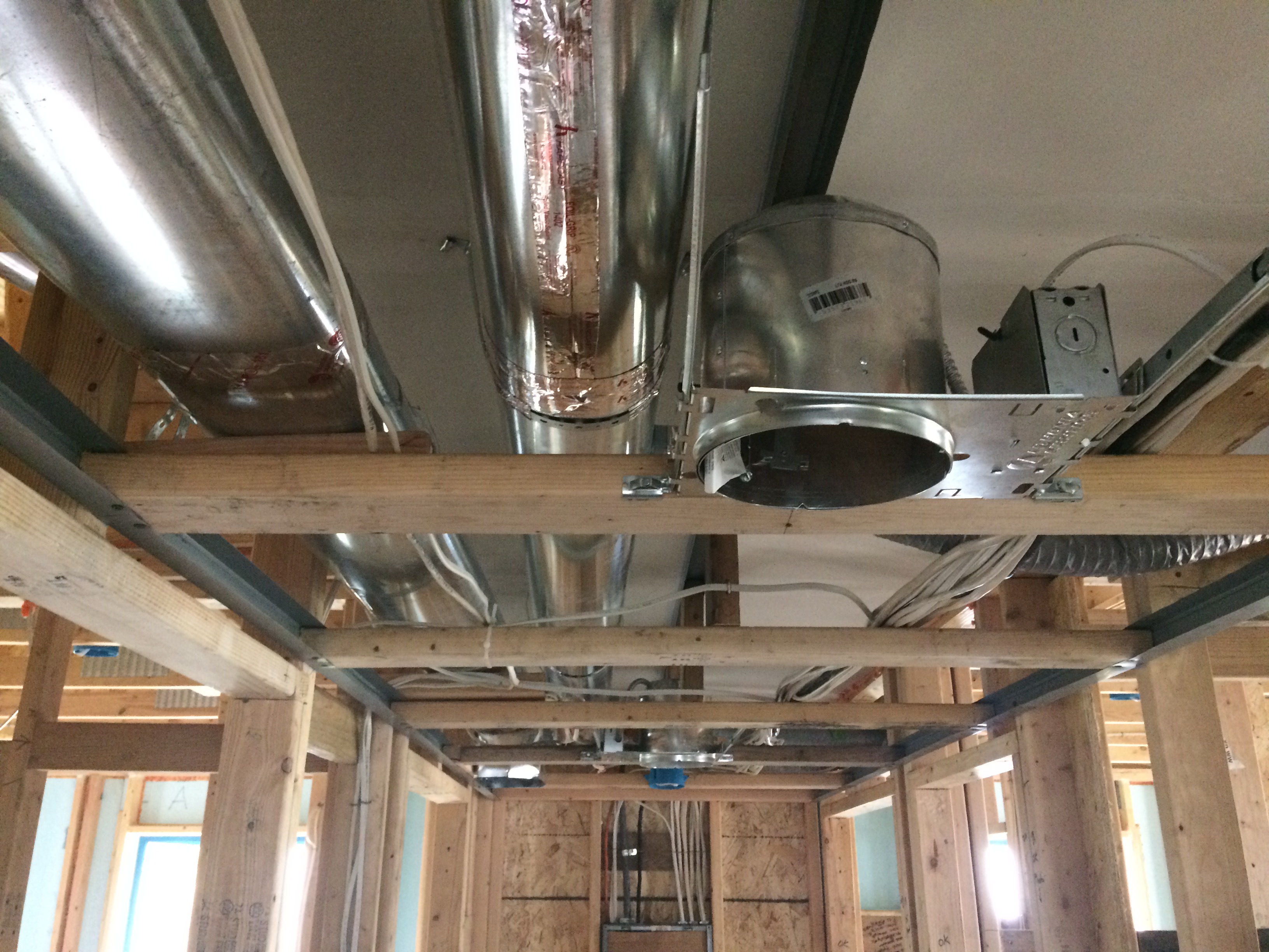
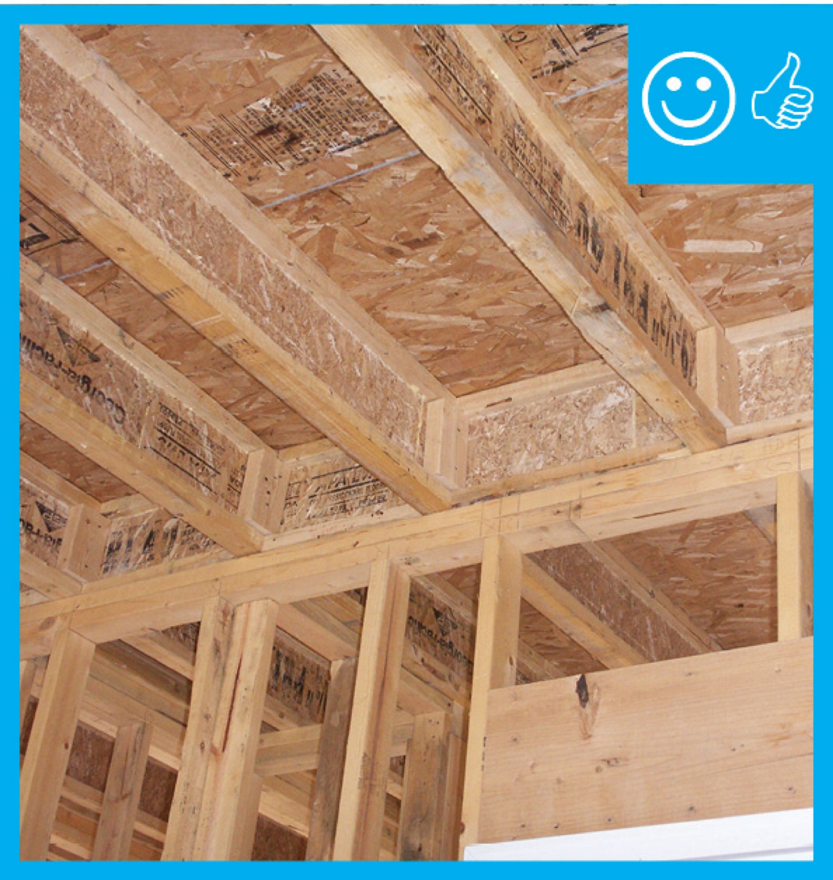
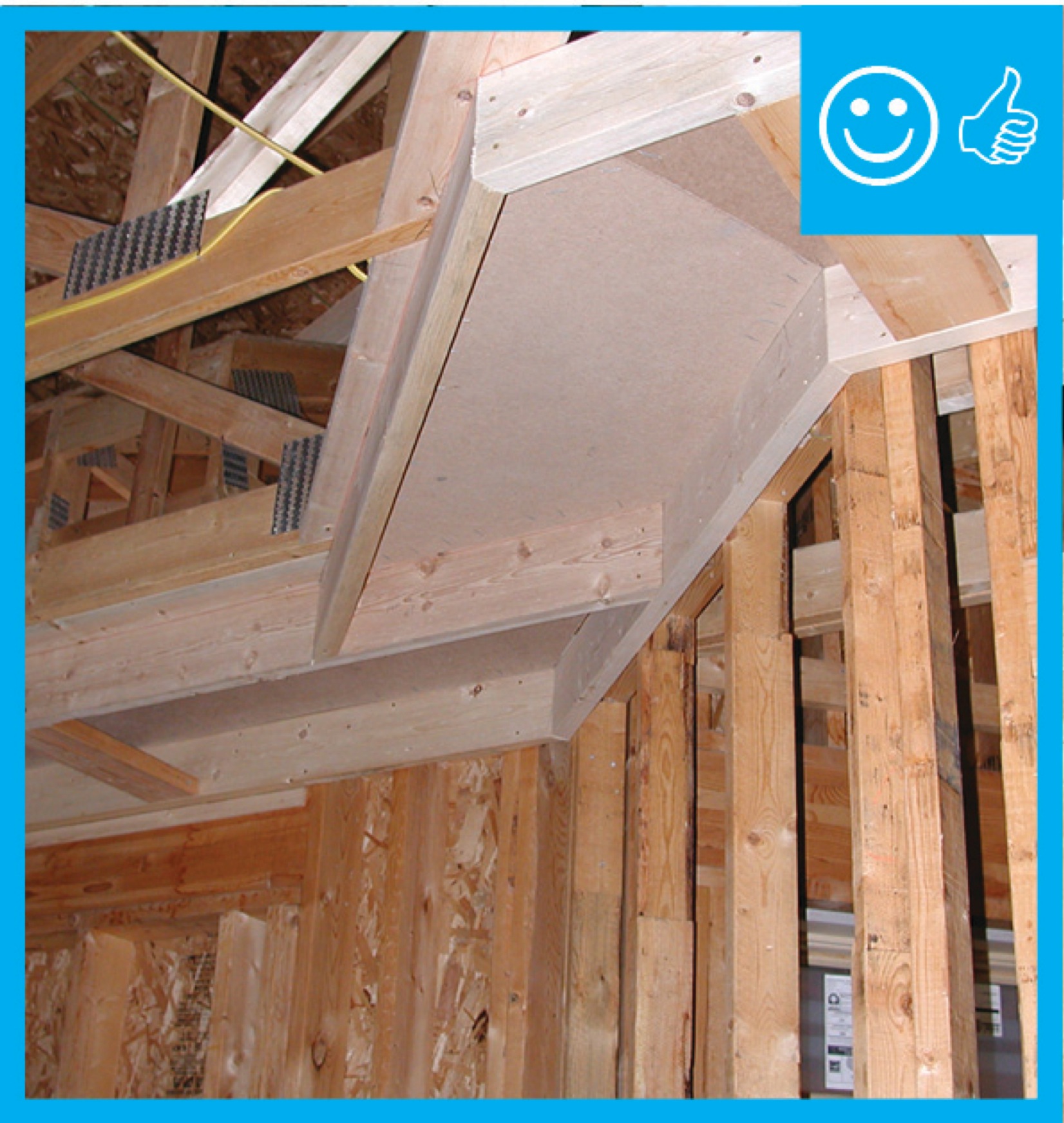
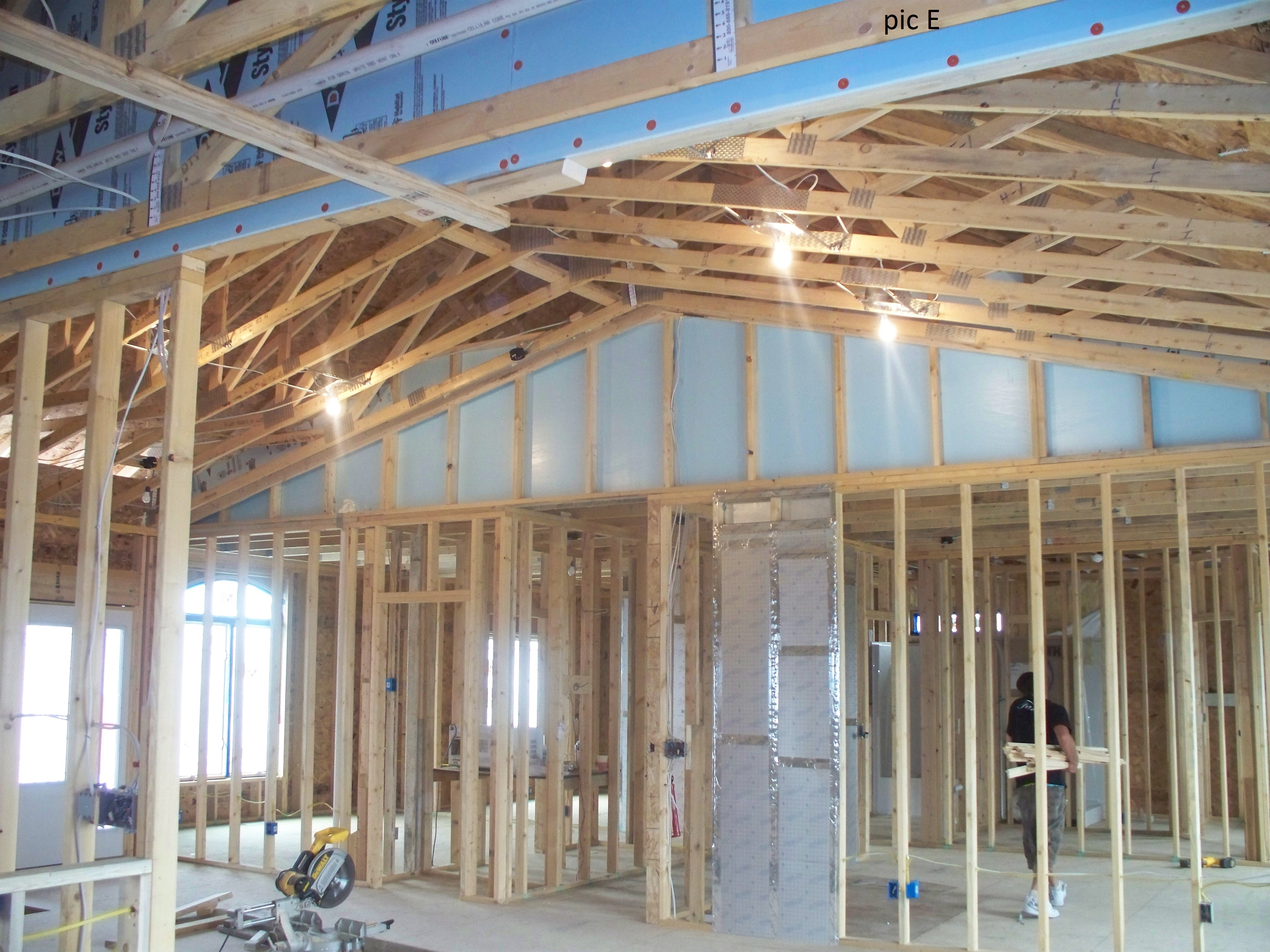
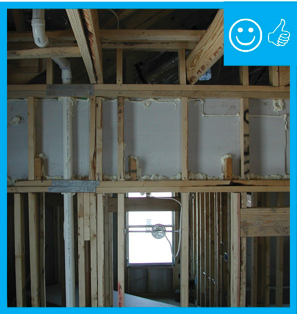
Right - Drywall is installed as an air barrier above the central hallway duct chase prior to installing the trunk ducts.
Image
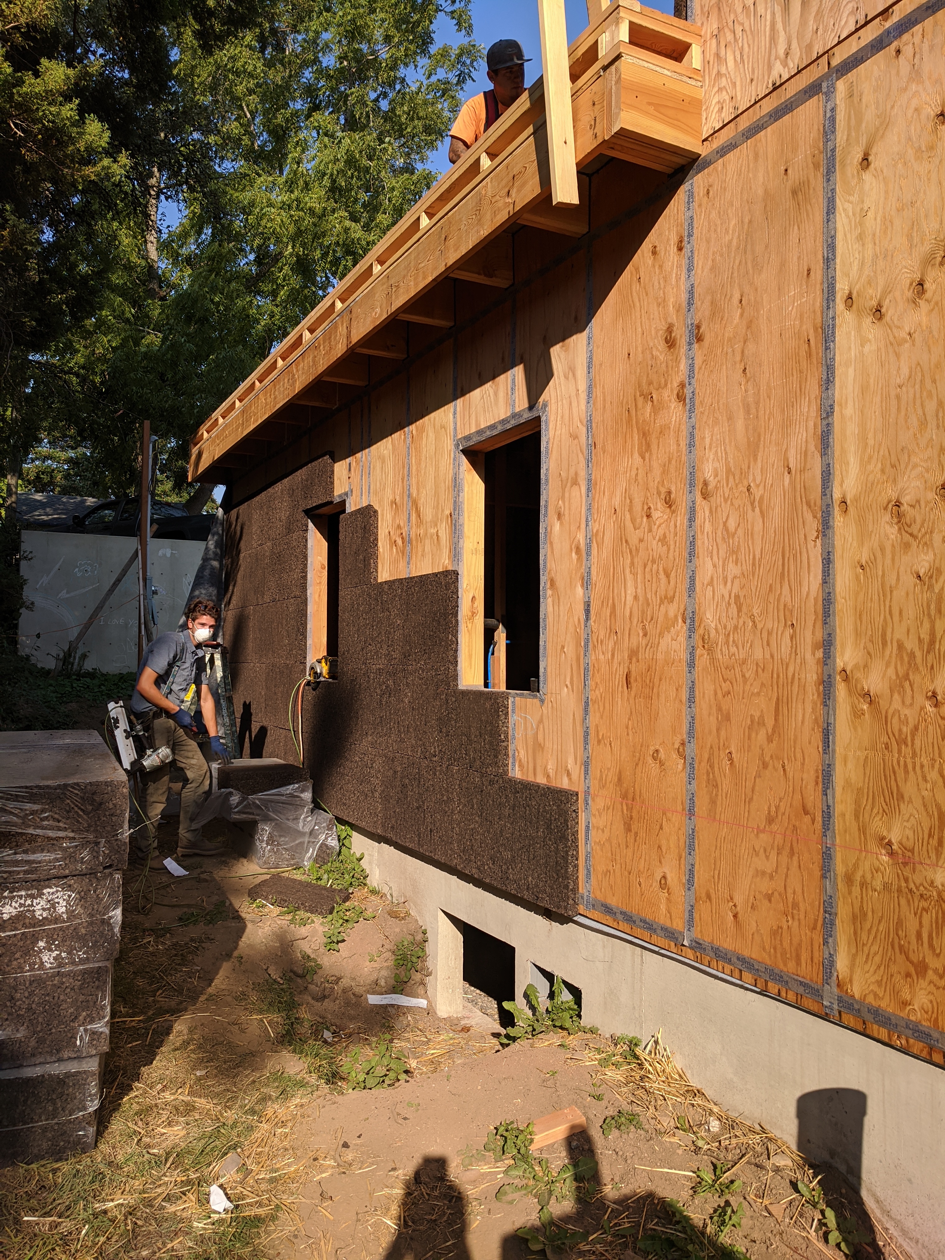
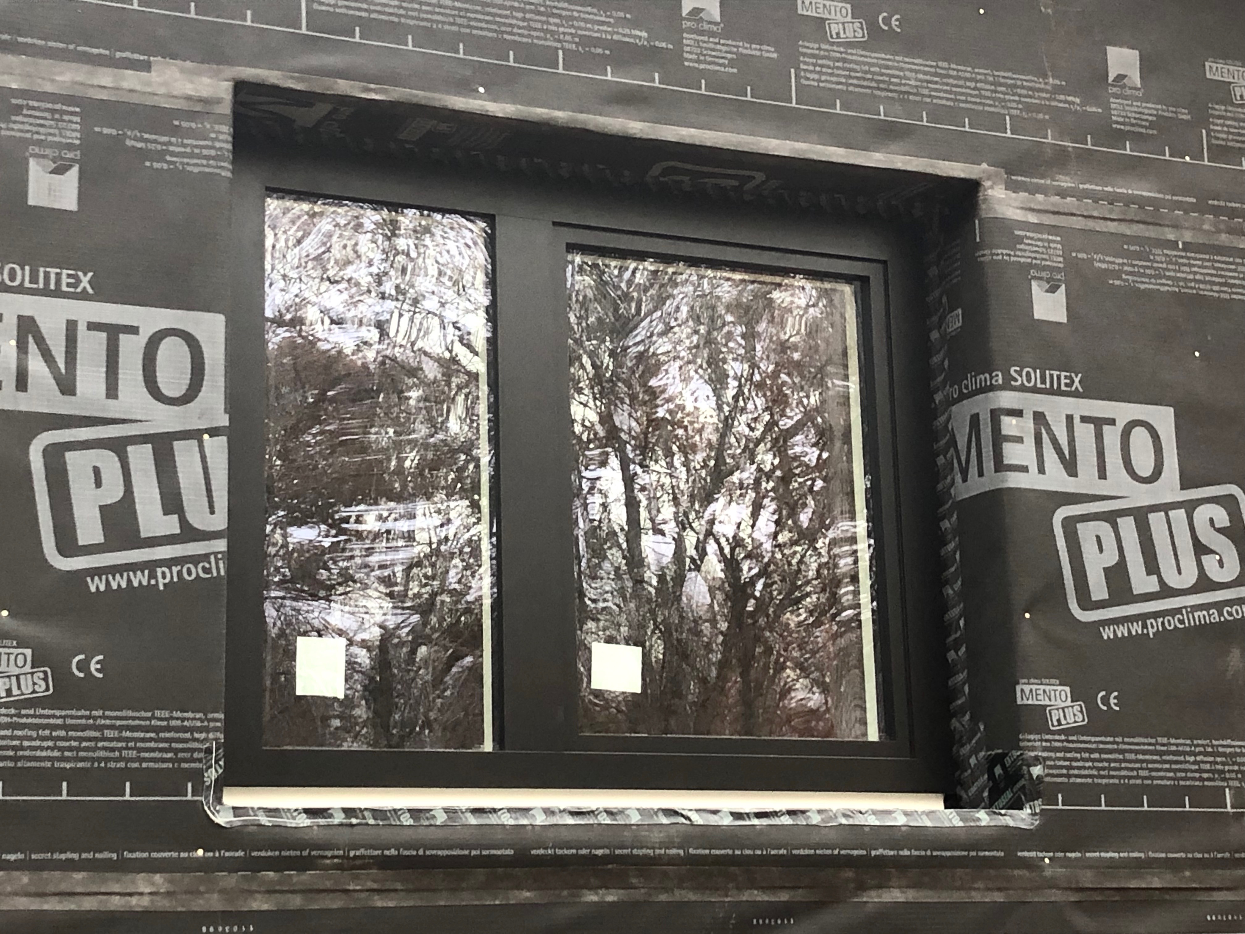
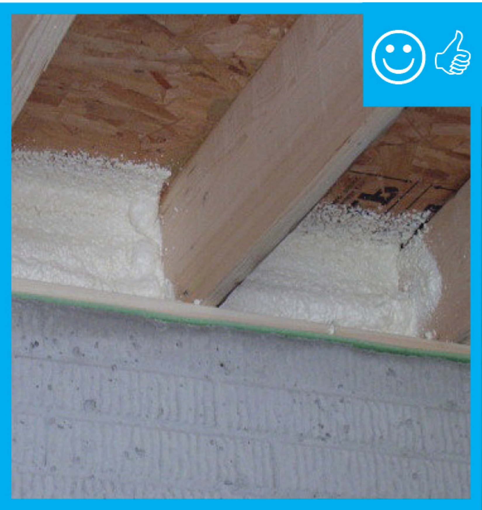
Taped plywood provides an air barrier beneath the cork insulation installed on the exterior of this home.
Image
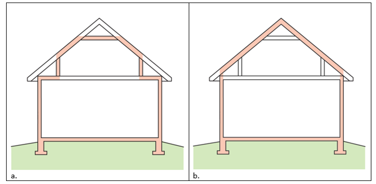
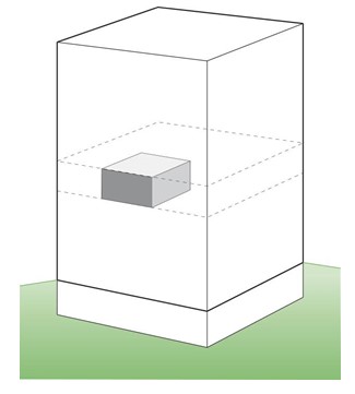
A 1- and ½-story home with a room located in the attic and the thermal boundary located at either a) the walls and ceiling of the attic room with small vented attic spaces or b) the roof line for an unvented attic
Image
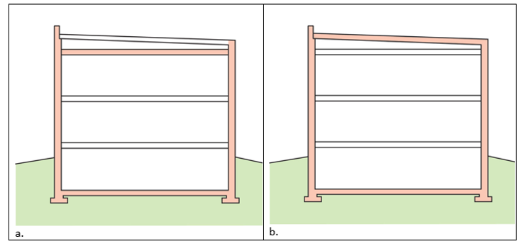
A low-sloped shed roof with the thermal boundary located at either a) the flat ceiling with a vented attic or b) the roof line for an unvented attic
Image
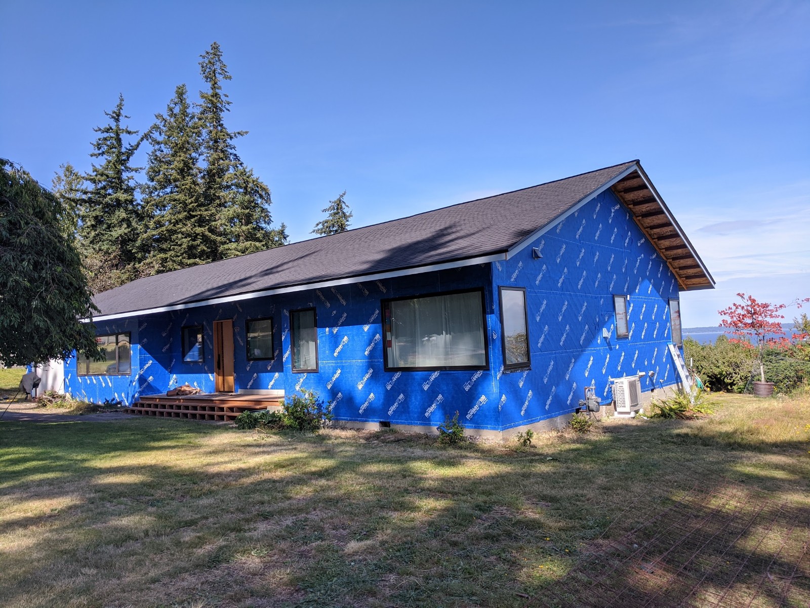
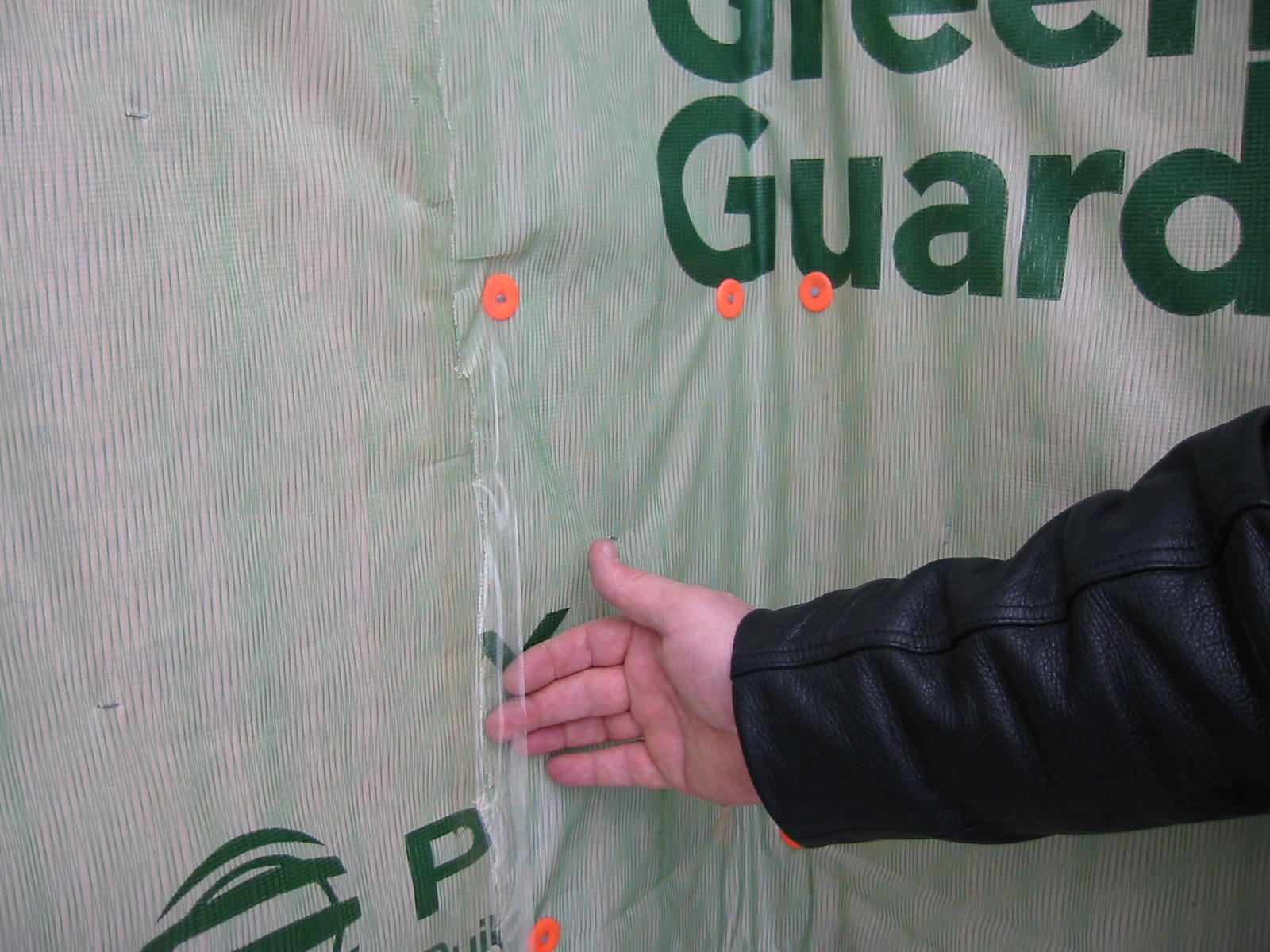
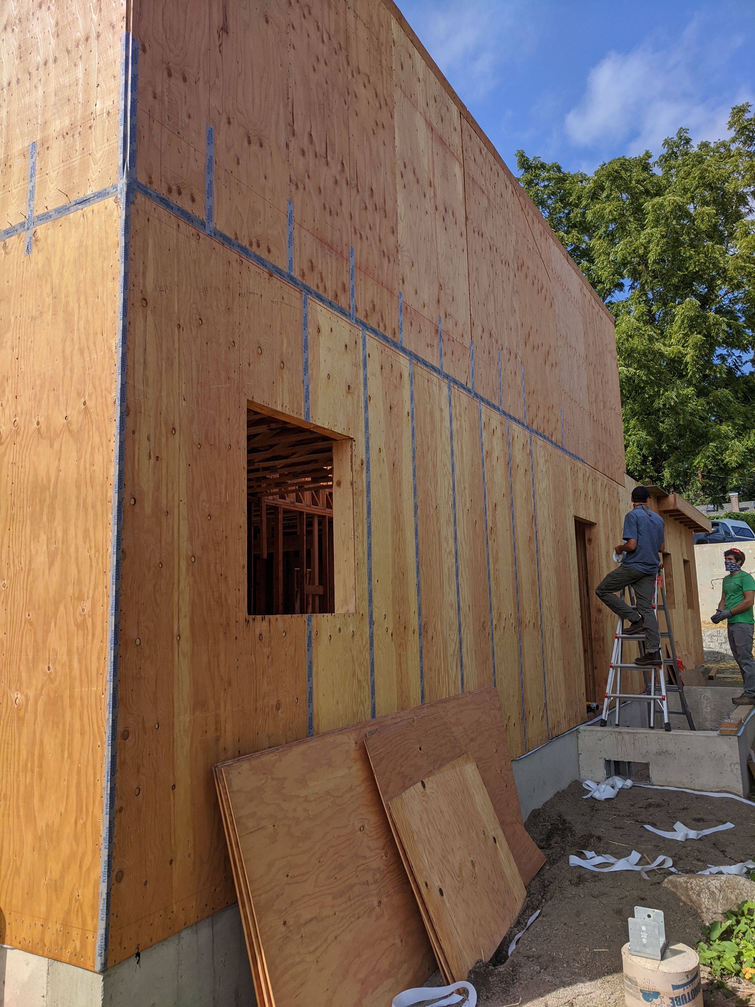
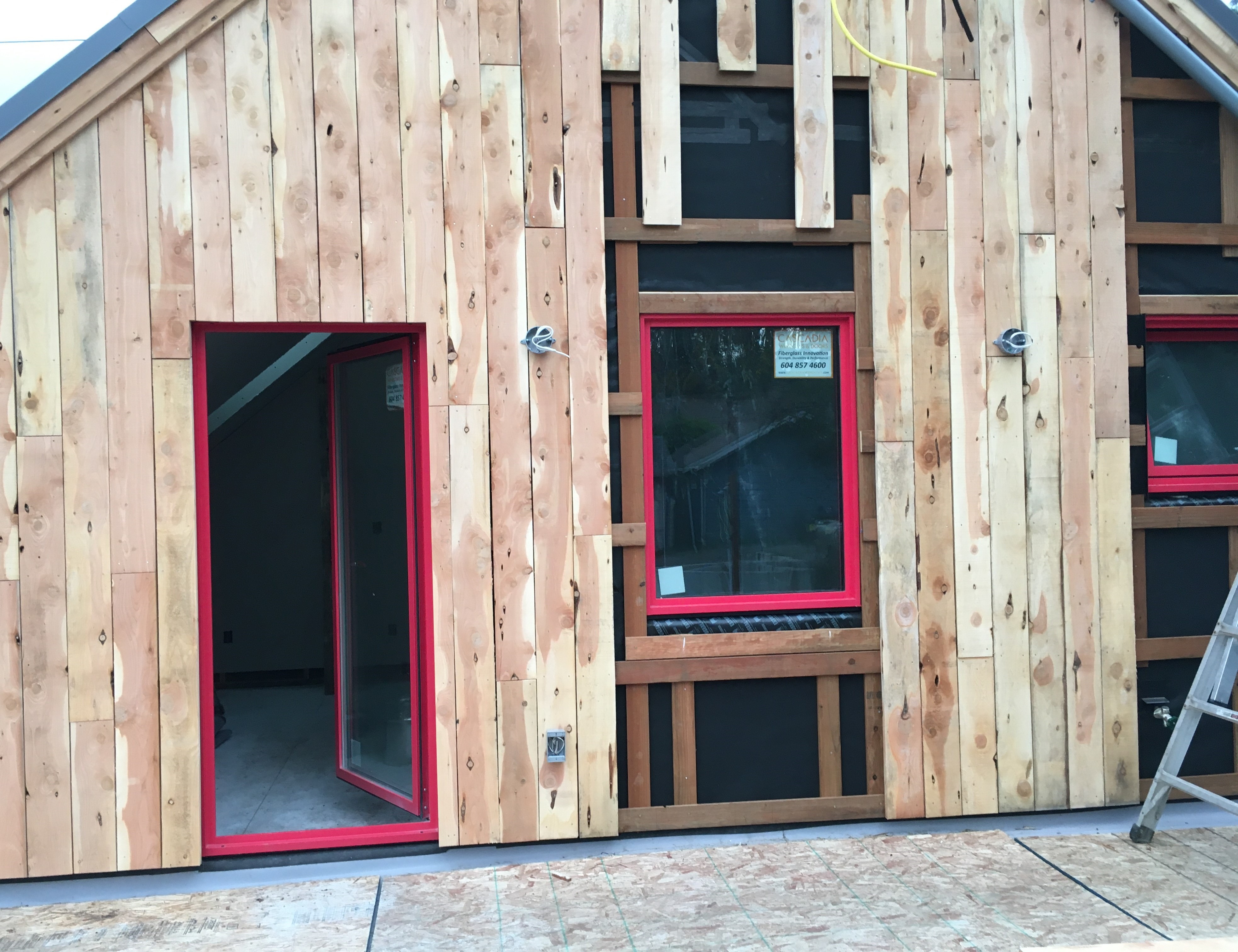
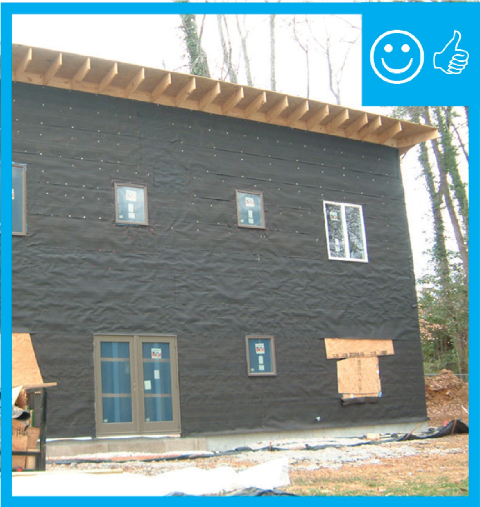
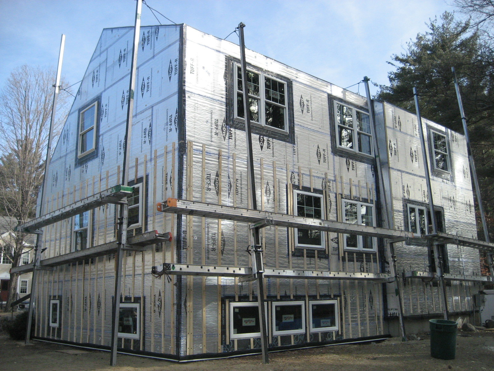
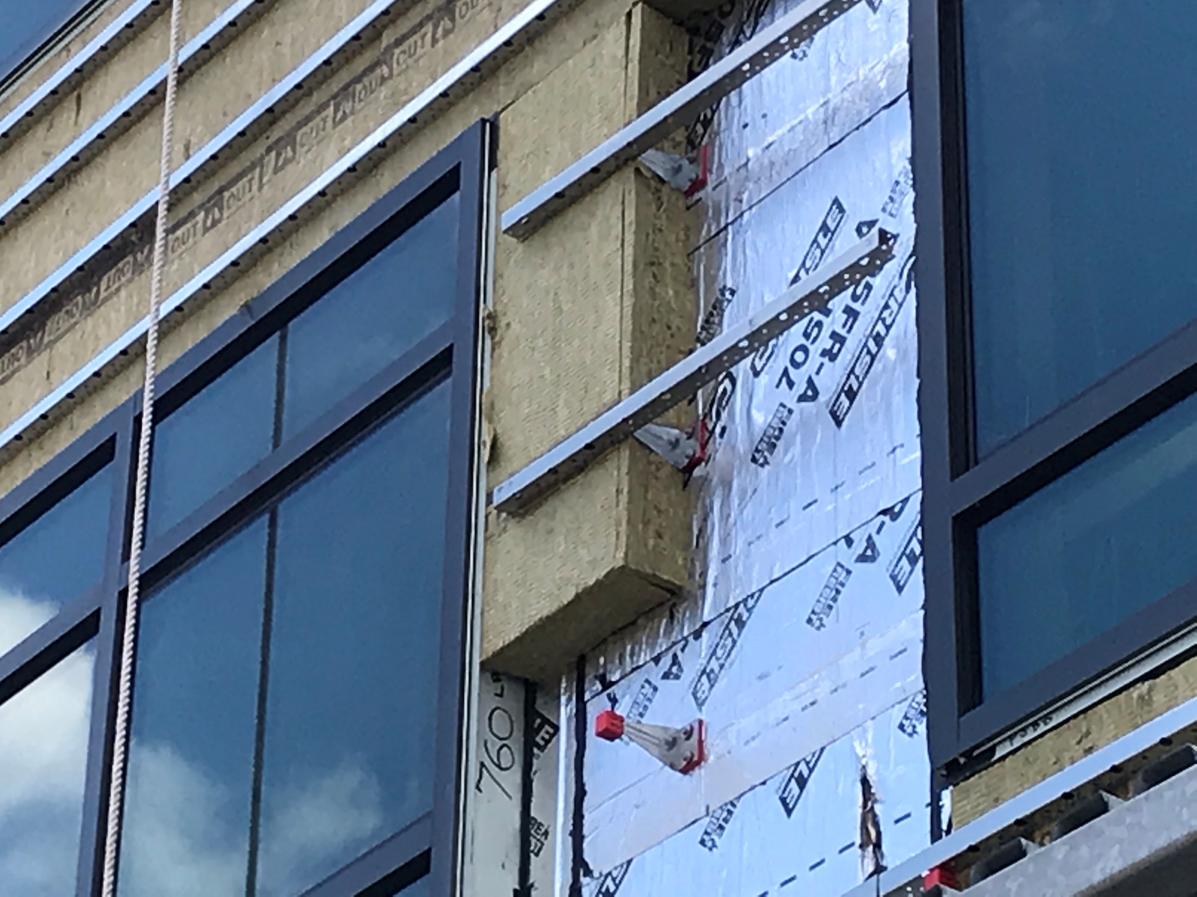
A self-adhering weather-resistant barrier is installed over the existing sheathing of this retrofit home to provide air sealing and a drainage plane before installing new metal and wood siding on the home.
Image
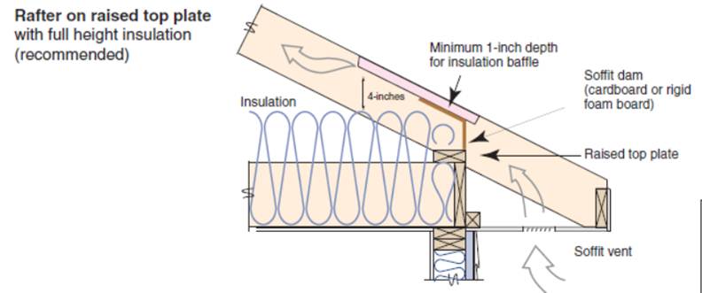
A site-built rafter roof with a raised top plate allows for more insulation underneath.
Image
After all holes through the ceiling are air-sealed and the baffles have been installed, then the insulation can be installed.
Image
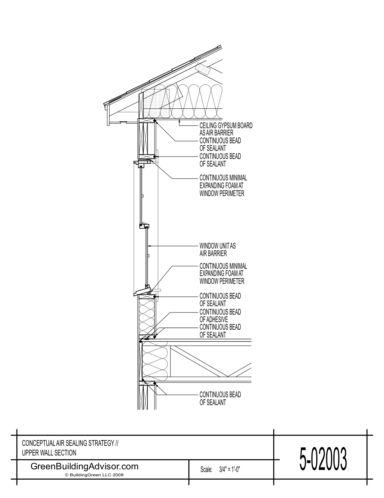
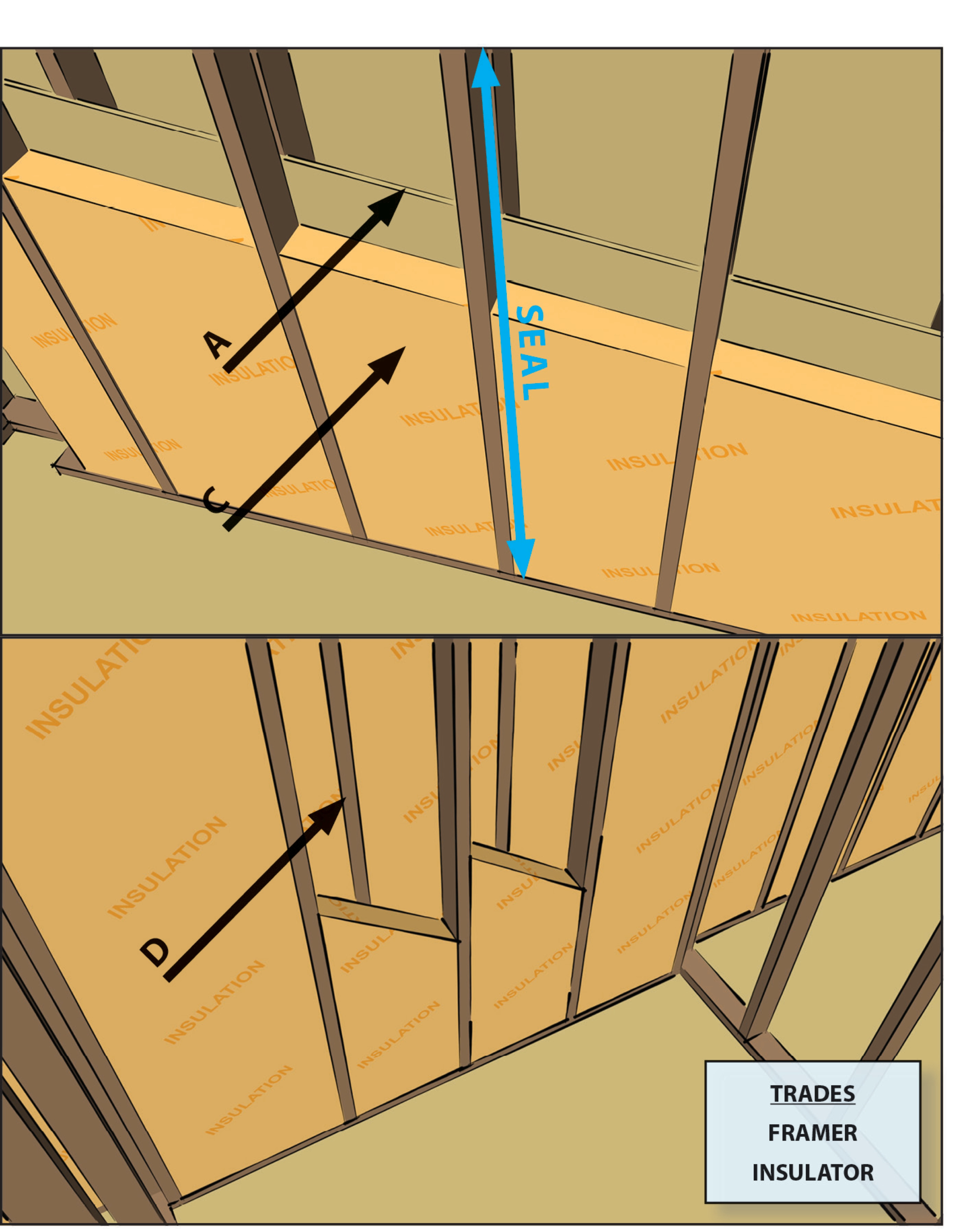
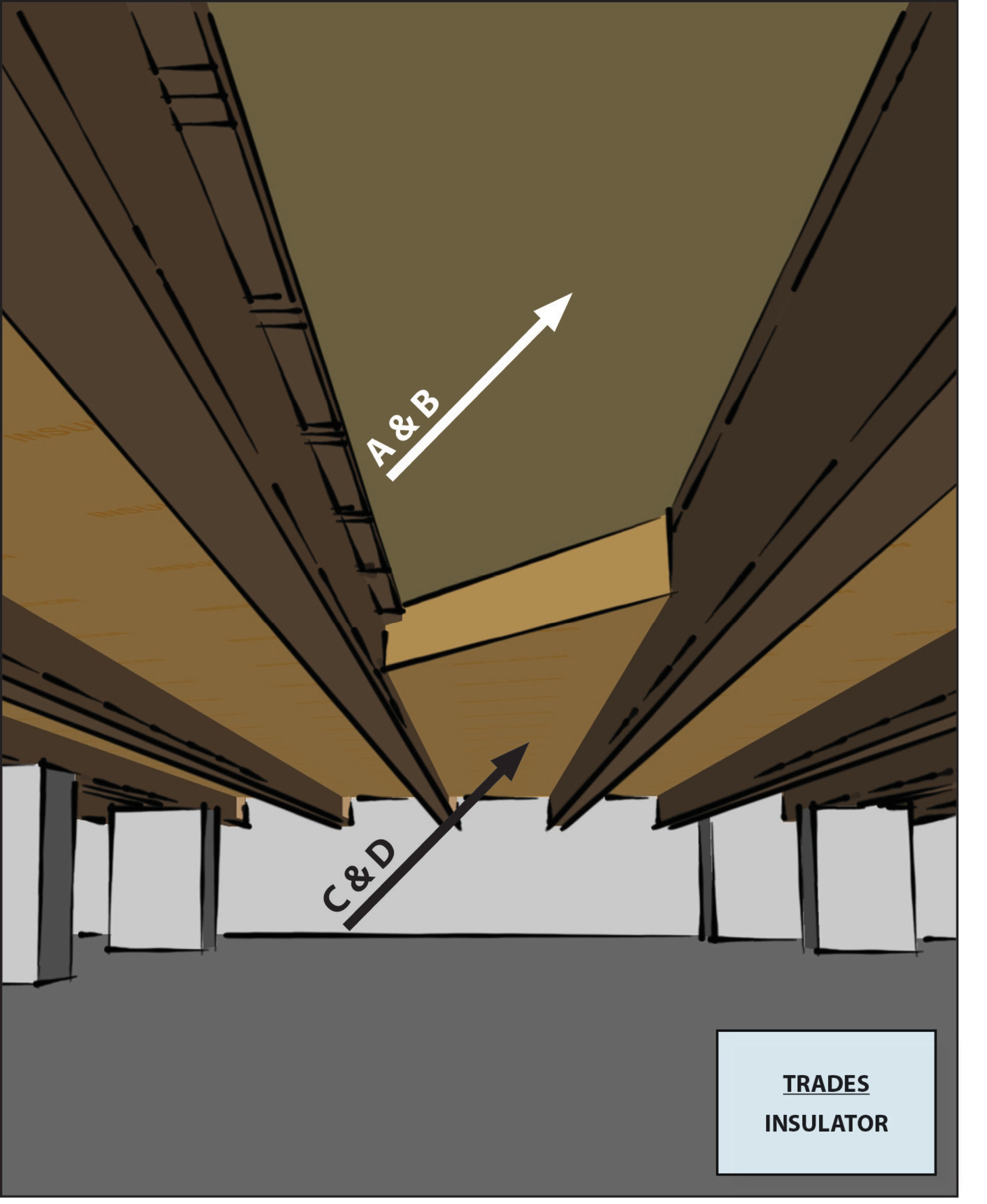
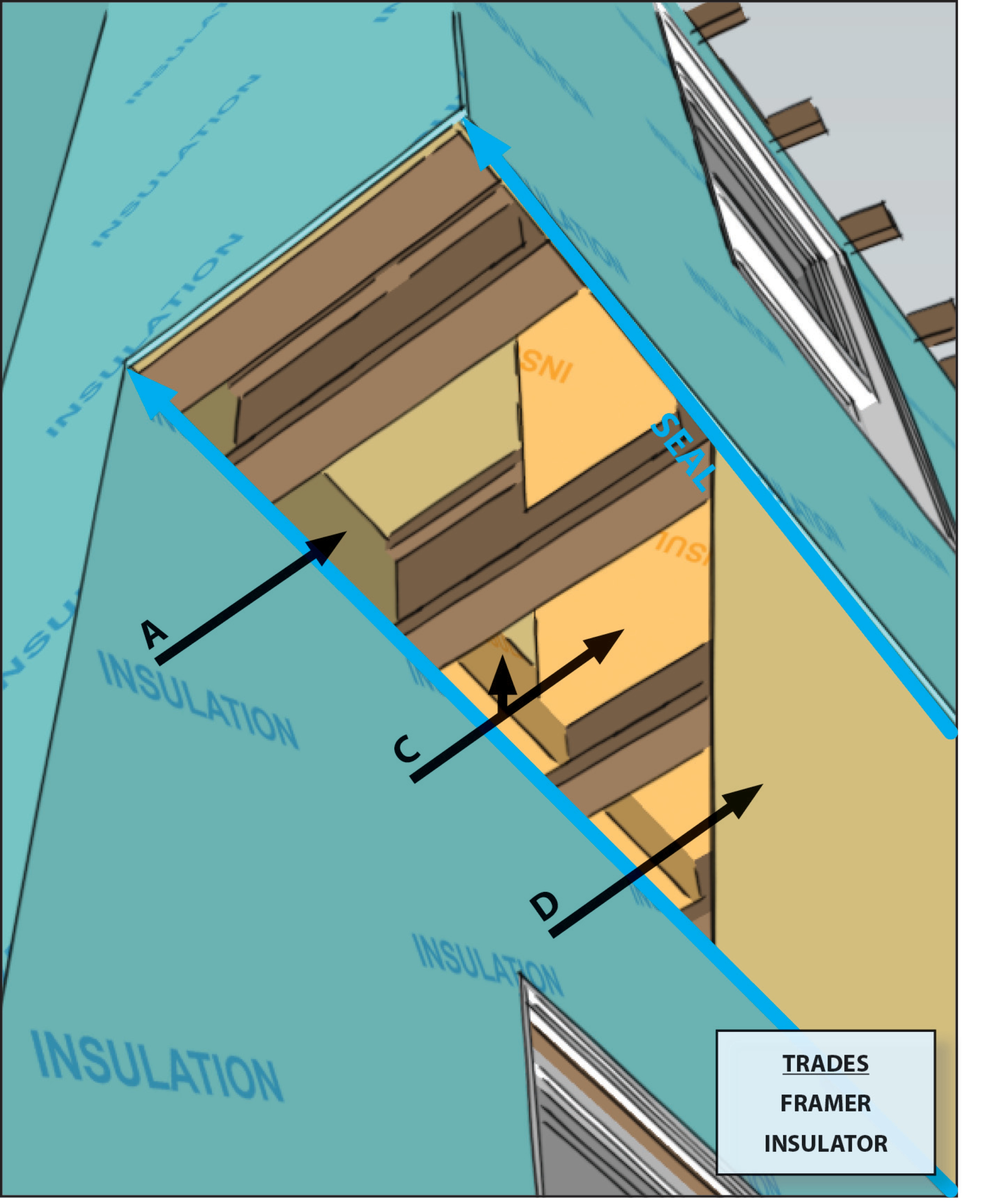
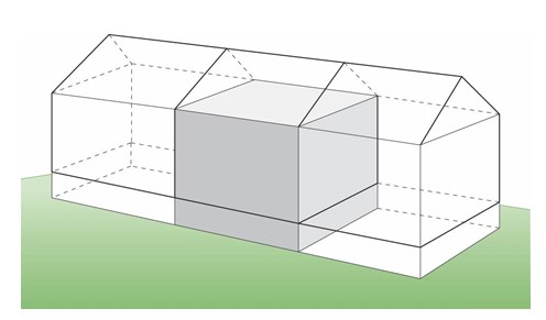
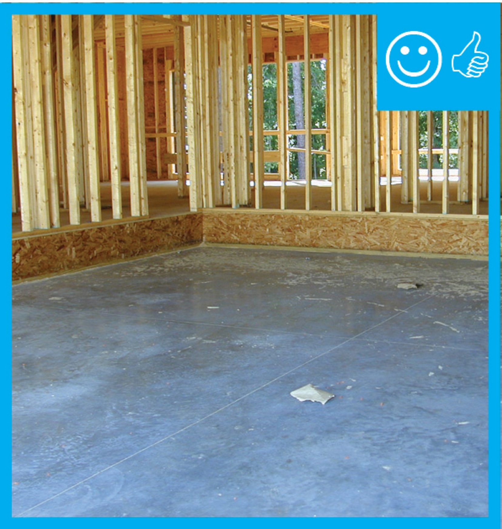
Air barrier is continuous across several components of the lower section of wall
Image
Air seal and insulate double-walls that are half-height or full-height walls used as architectural features in homes.
Image
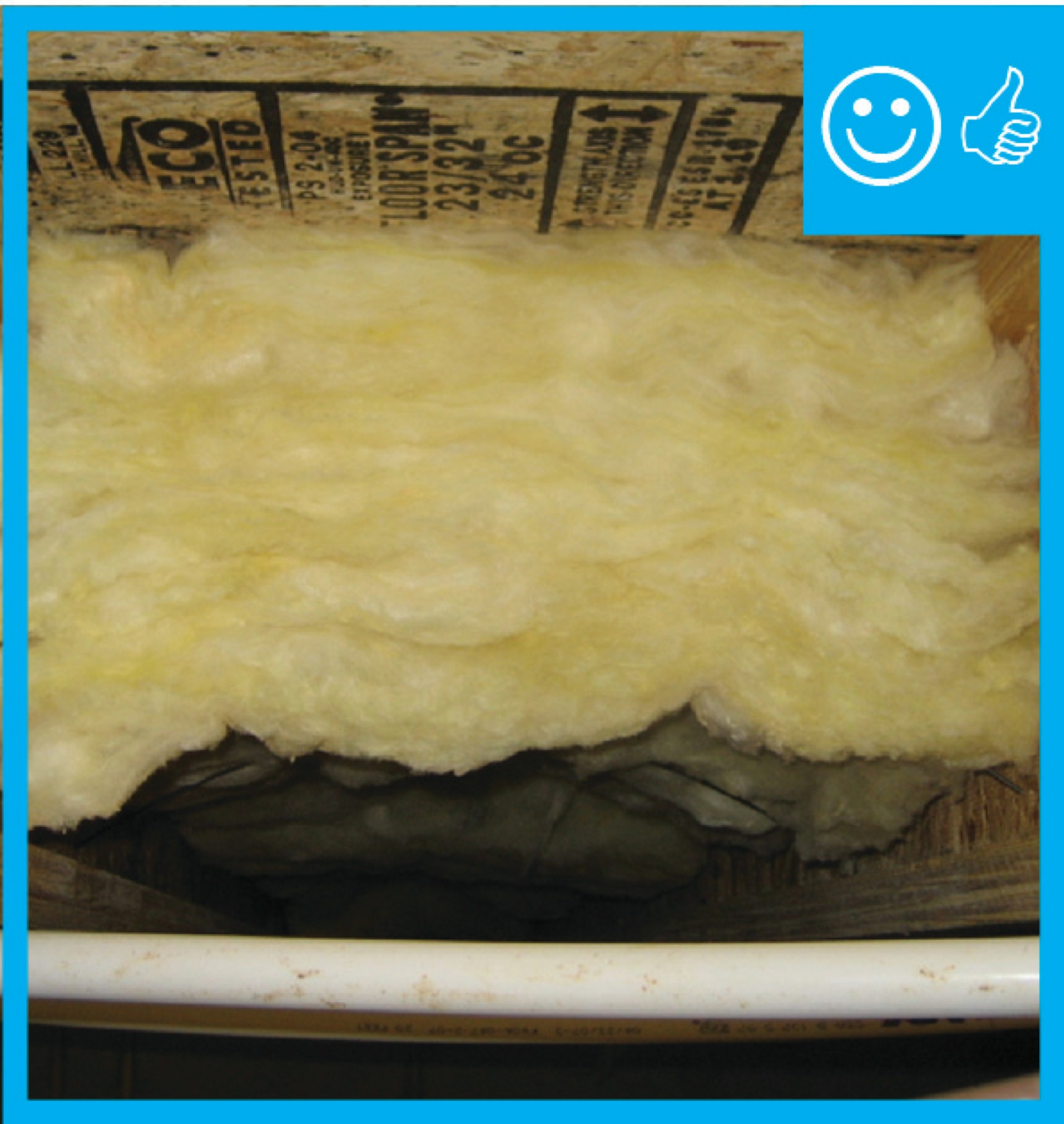
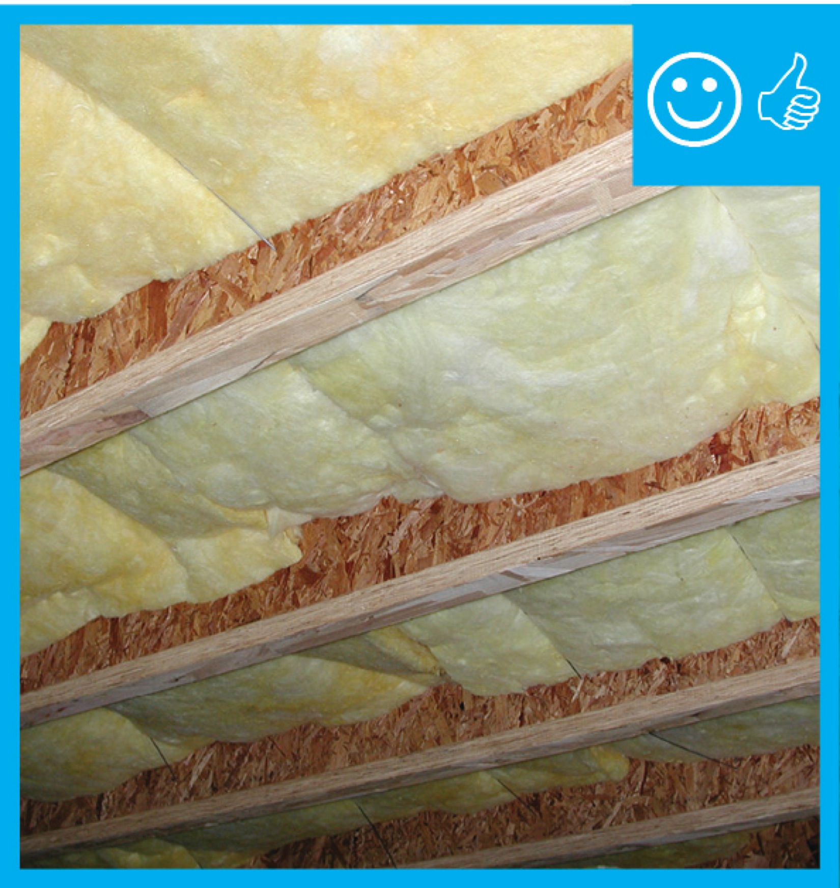
Air seal the floor above an unconditioned basement or crawlspace and make sure floor insulation is in full contact with the underside of the subfloor.
Image
Air seal the top, bottom, and sides of a cantilevered floor cavity and ensure that insulation is in full contact with all sides without voids.
Image
Air-seal and insulate the rim and band joists of walls separating an attached garage from the home’s conditioned space.
Image
Air-seal the floor above a garage when there is living space above the garage and make sure floor insulation is in full contact with the underside of the subfloor.
Image
Image

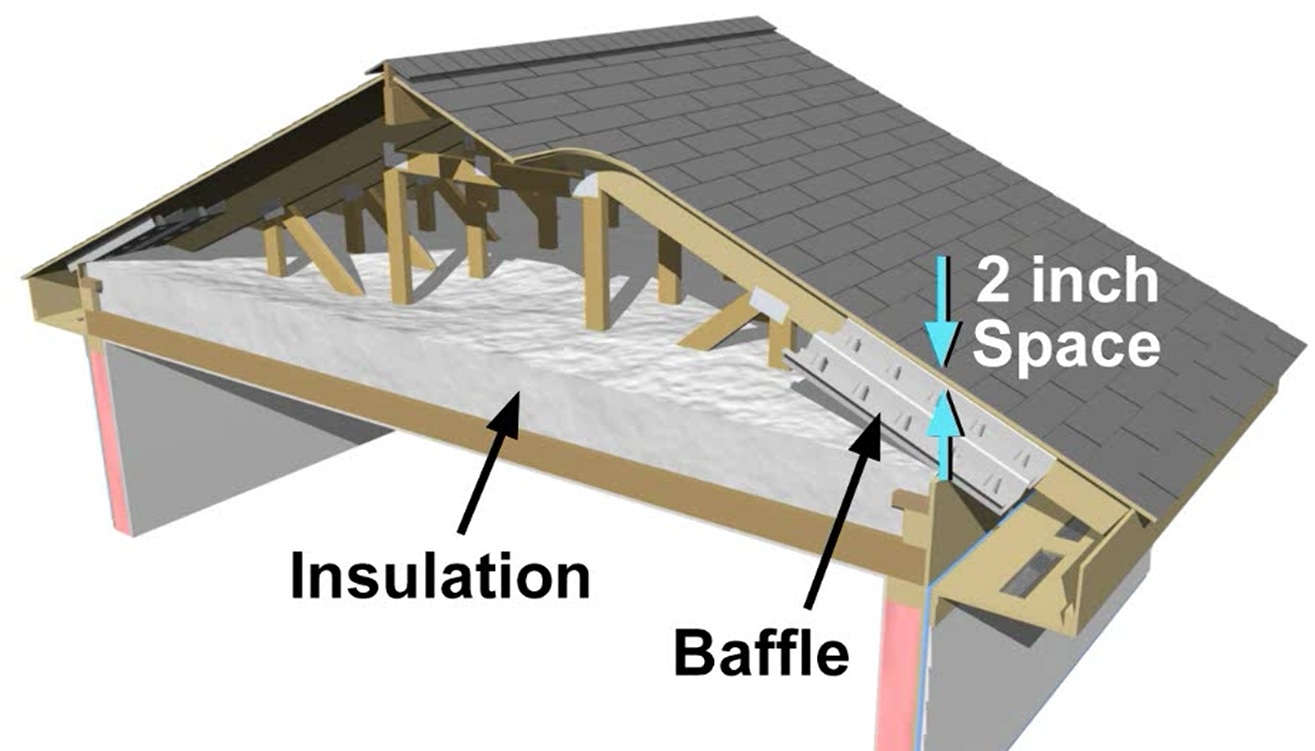
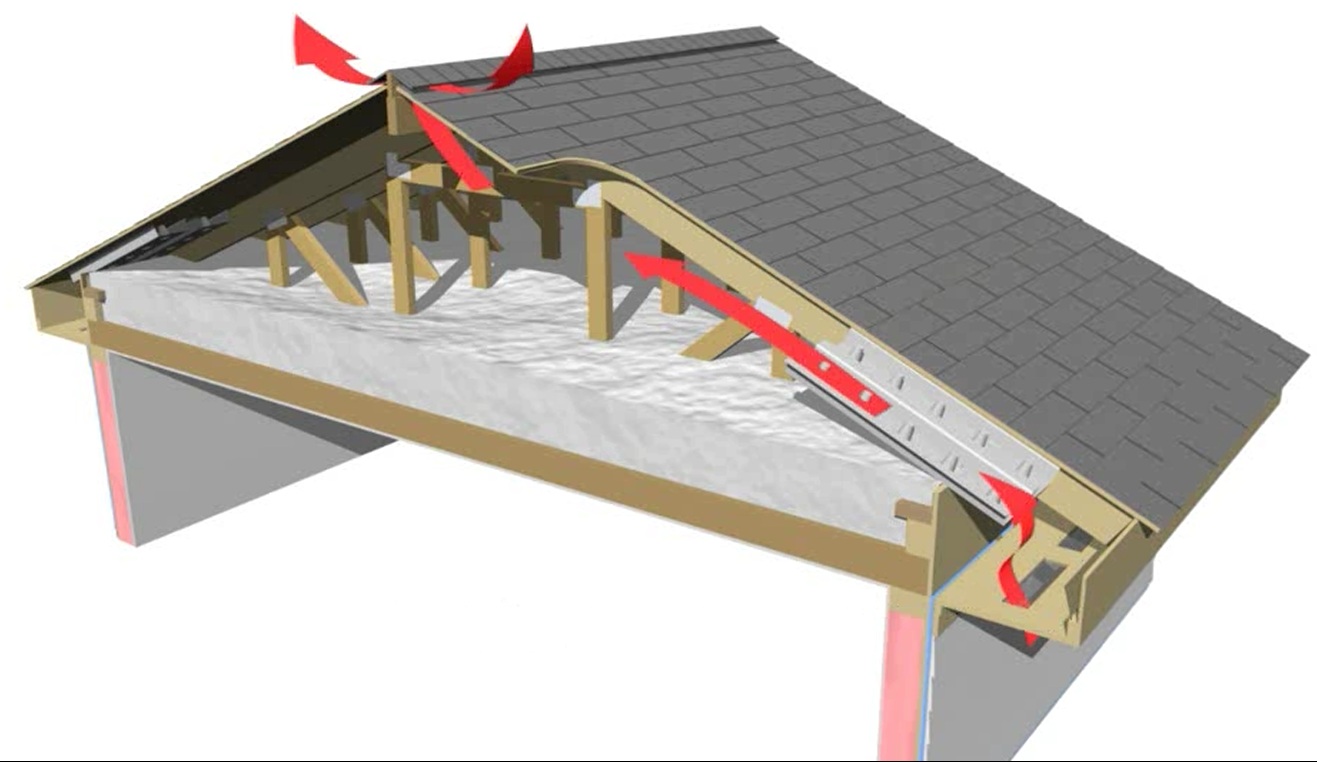
Baffles provide an air space over the insulation to guide ventilation air from the soffit vents up along the underside of the roof deck
Image
Image
Image
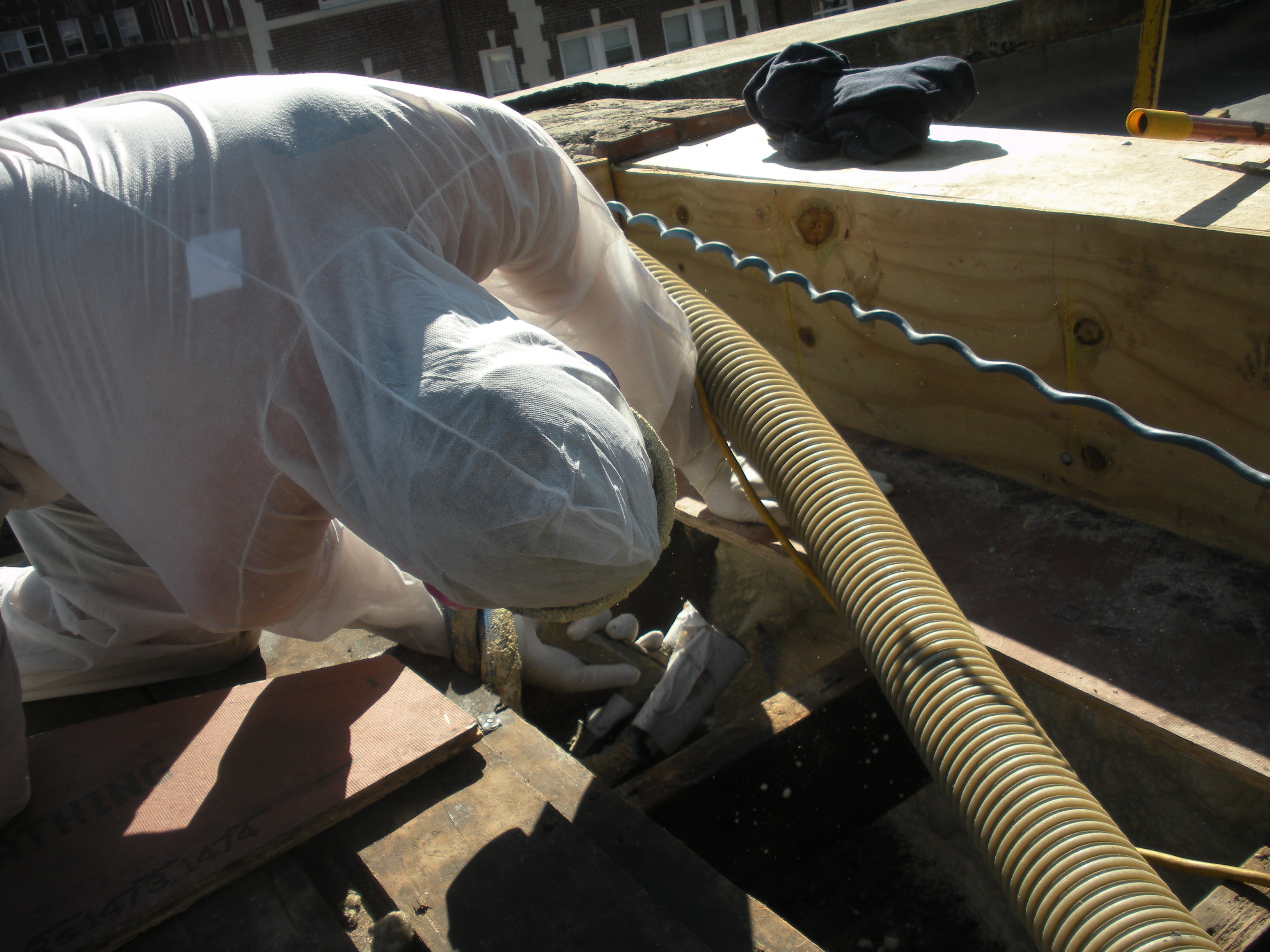
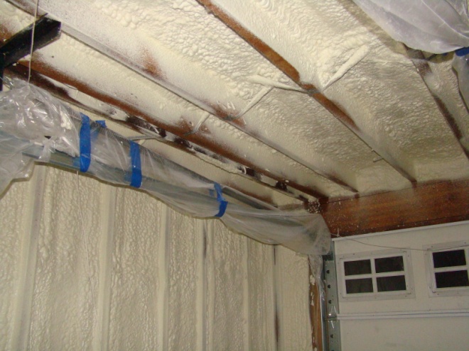
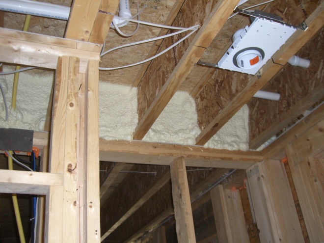
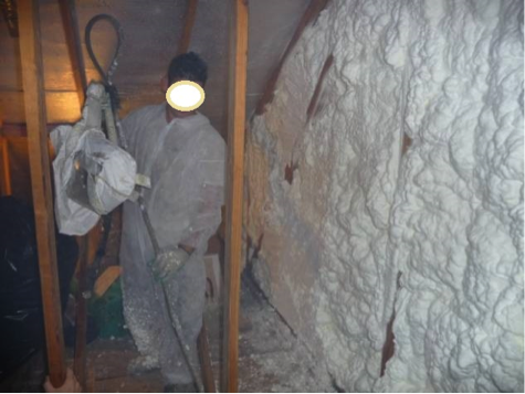
Closed-cell foam is sprayed into roof cavities along the masonry parapet wall to form a continuous air barrier between the wall and the sheathing of the flat roof
Image
Closed-cell spray foam fills the roof joist cavities forming an air barrier between the masonry parapet wall and the roof sheathing
Image
Compartmentalization isolates each dwelling unit within a multistory multifamily building, preventing vertical and horizontal airflow between units
Image
Compartmentalization isolates each dwelling unit within a rowhouse, preventing horizontal airflow between units
Image
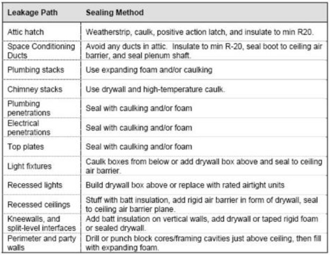
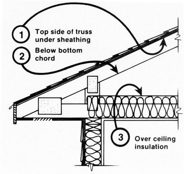
Correct air sealing methods for common attic bypass air leakage paths.
Image
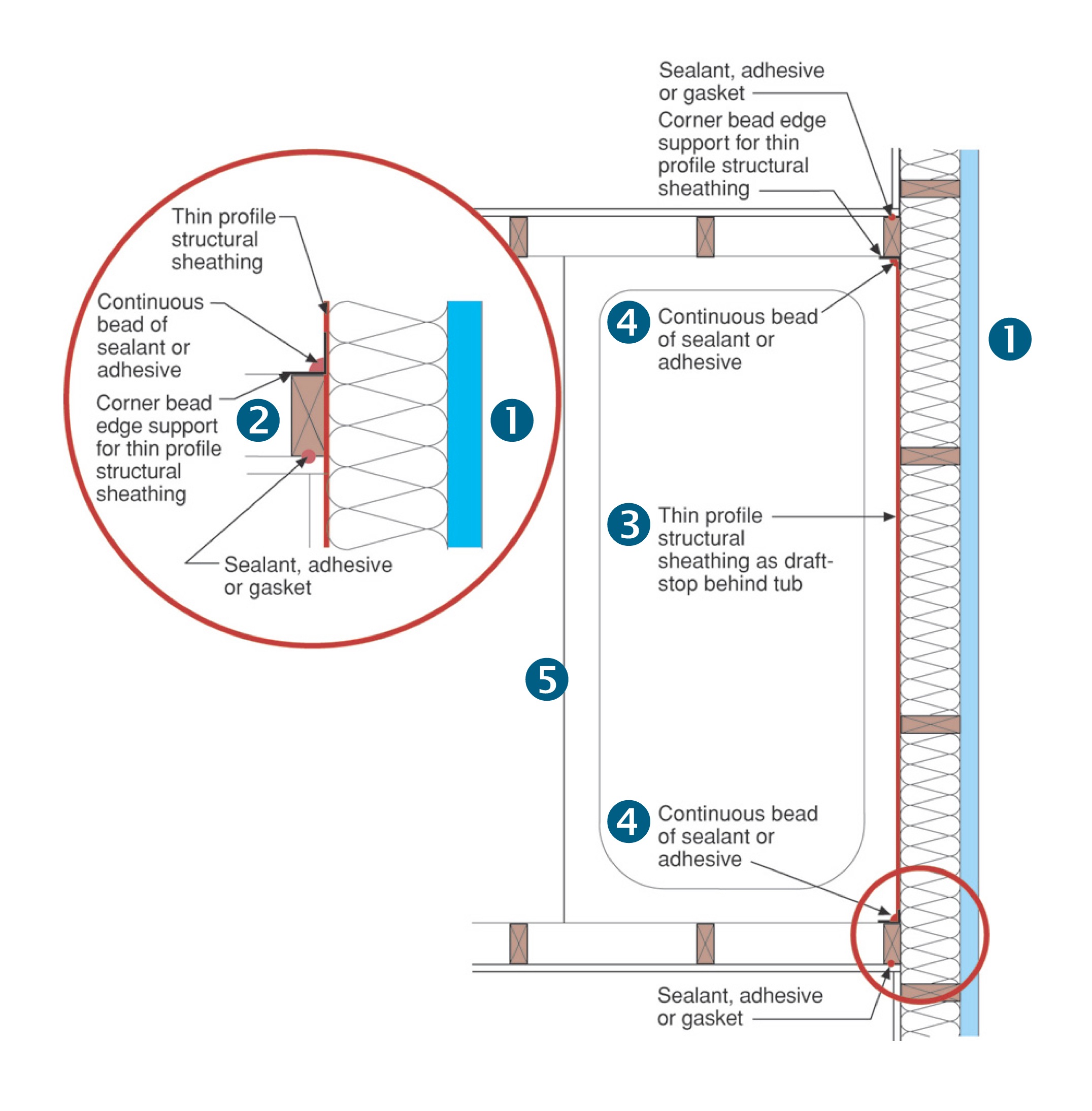
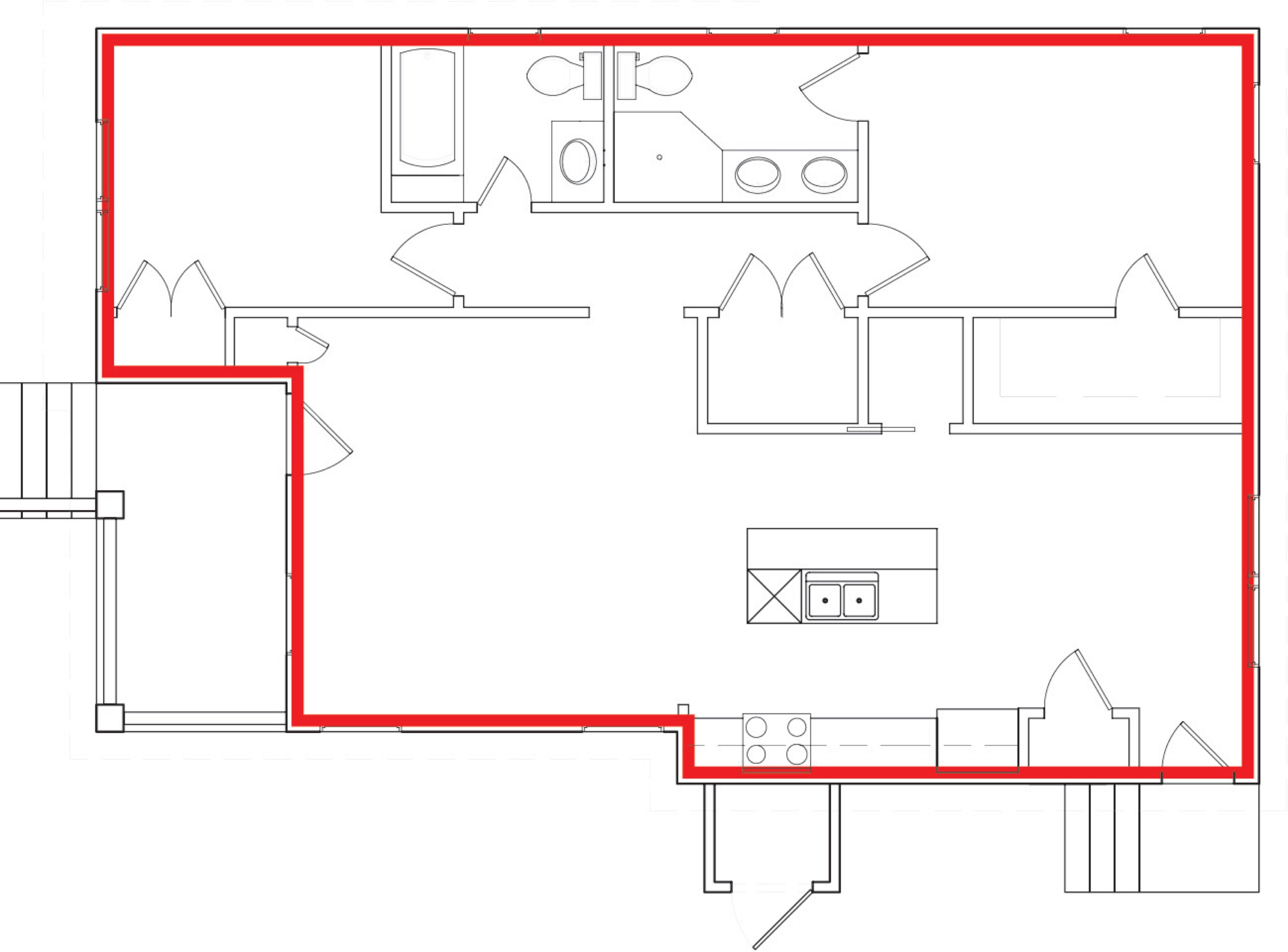
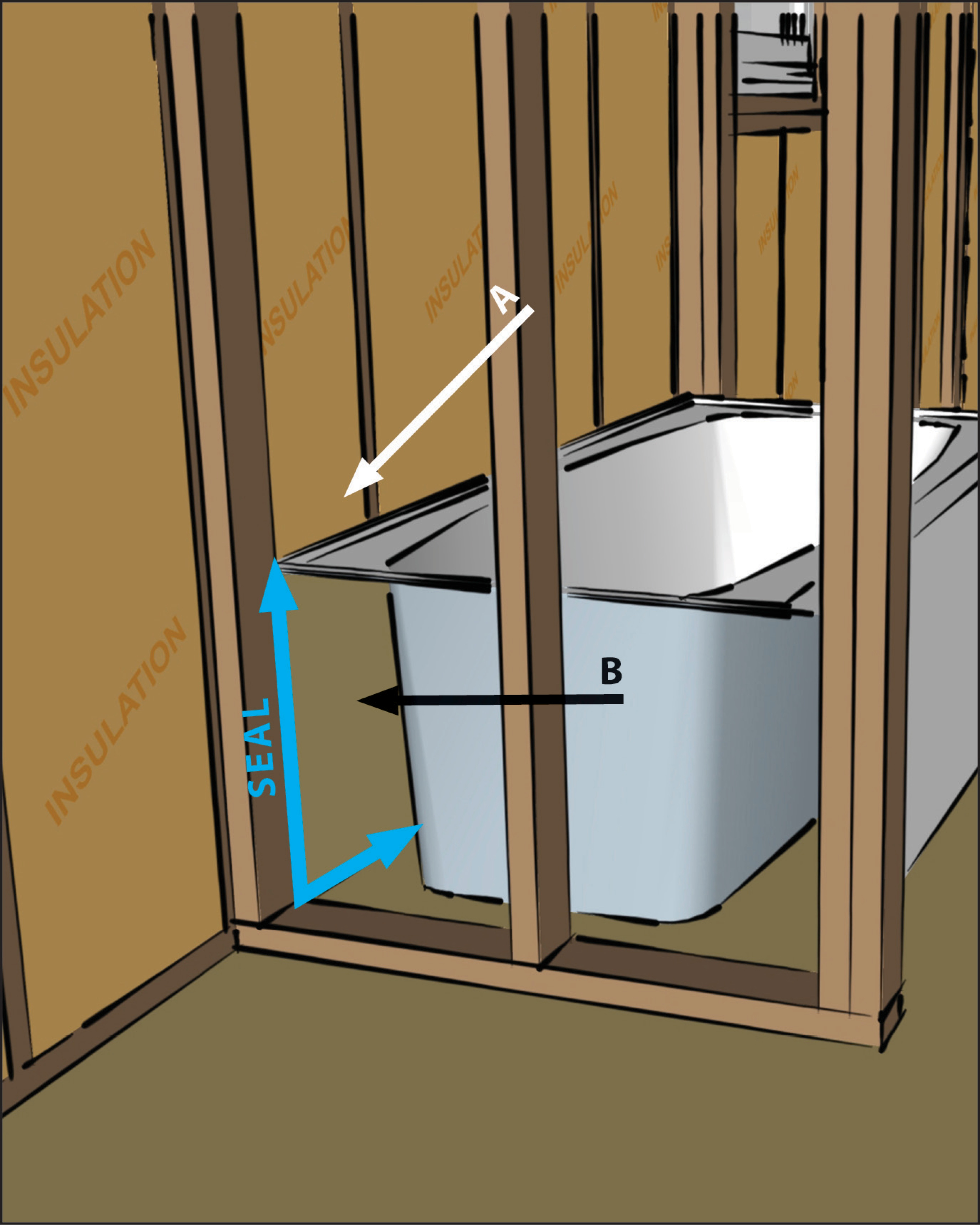
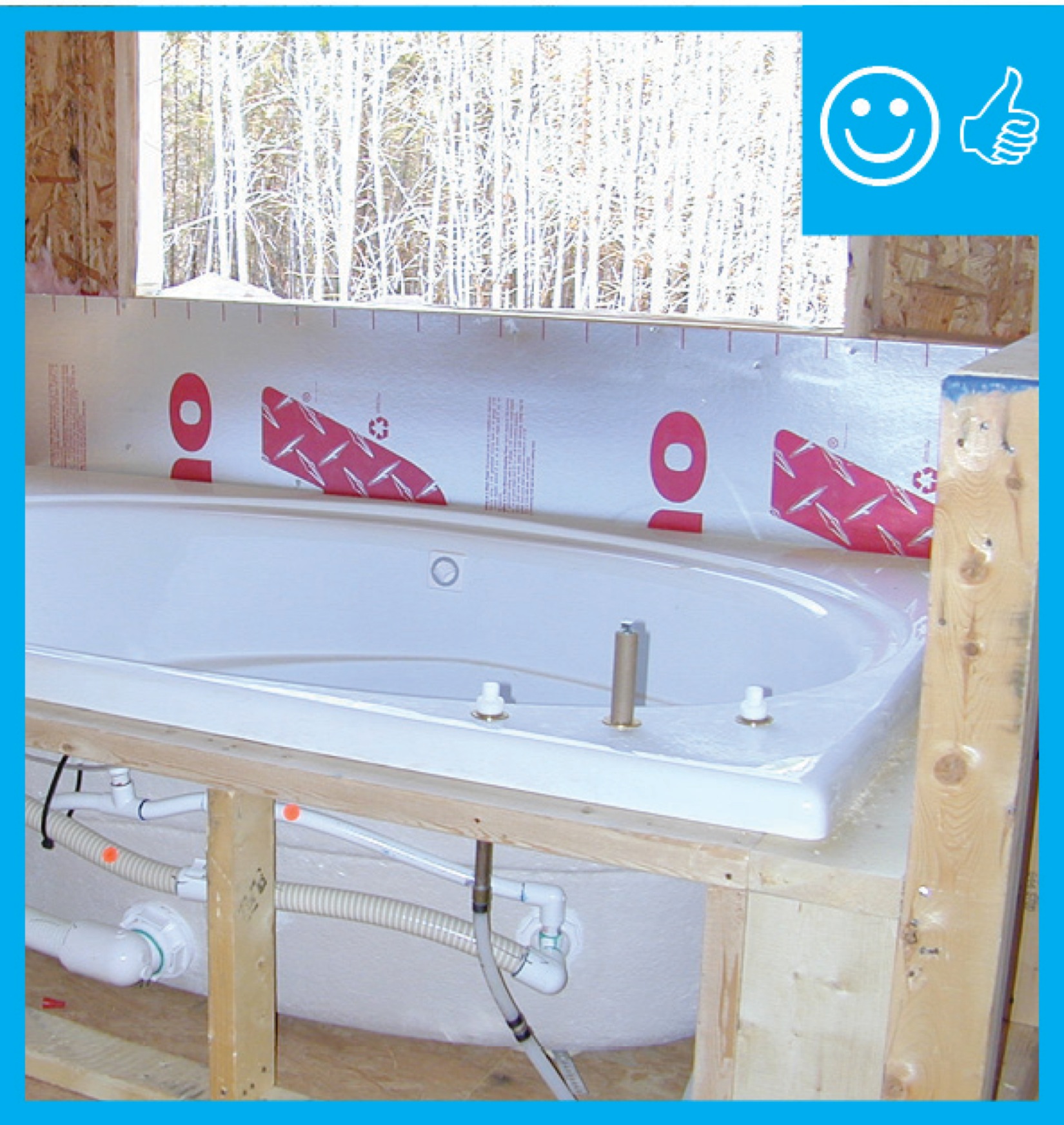
Draft stopping and air barrier at tub enclosure − plan view
Image
Image
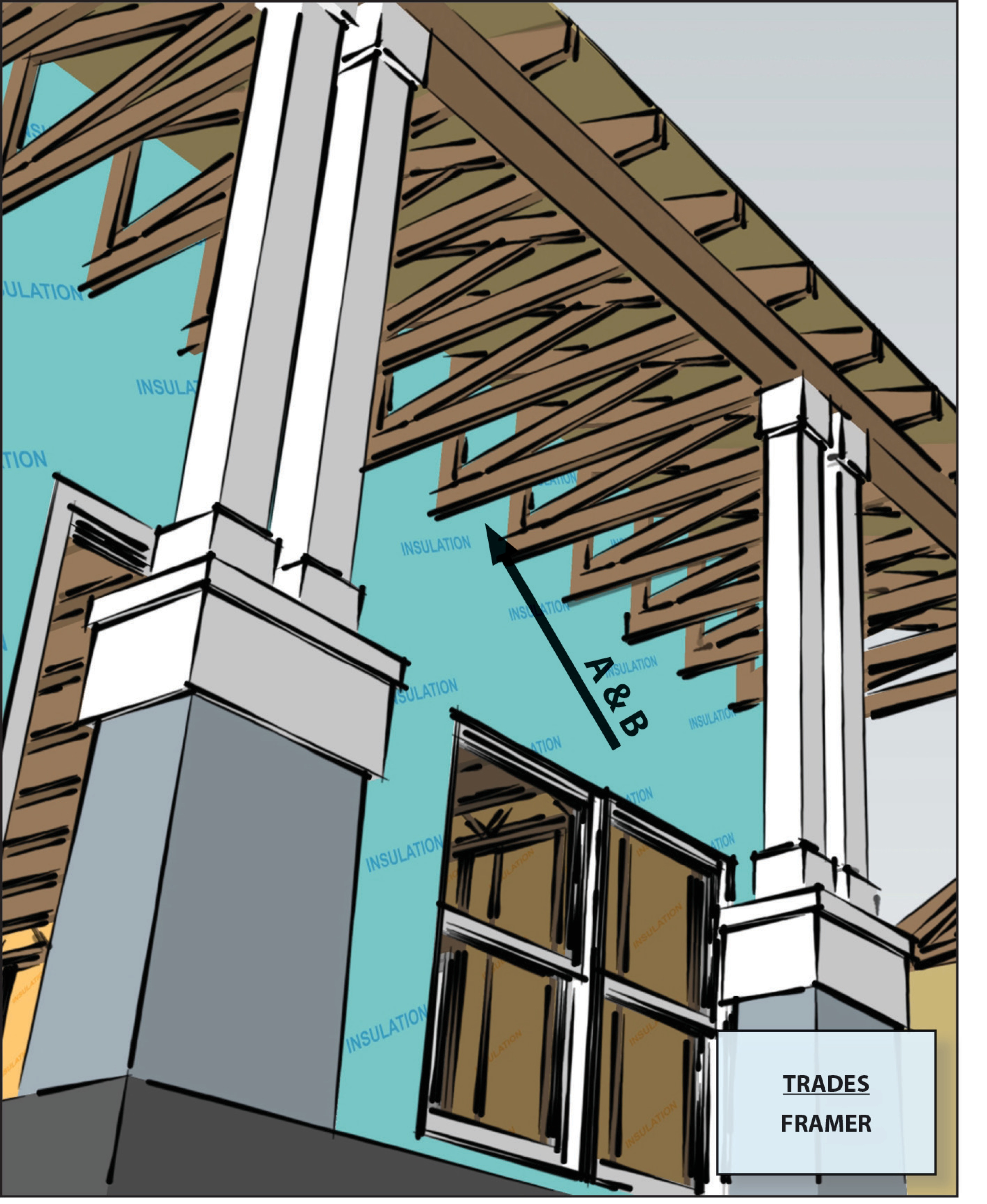
Drywall is installed before framing in dropped soffits to provide an air barrier above these duct chases.
Image

Image
Failure in attic insulation effectiveness caused by wind washing pushing insulation away from the edges of the attic space.
Image
Floor cavity air pressure is measured by placing a tube into the floor cavity through a small drilled hole
Image
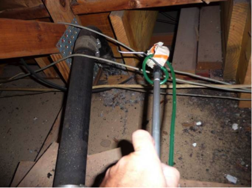
Floor cavity pressure is measured by inserting a tube into the floor cavity using an extension pole
Image
Image
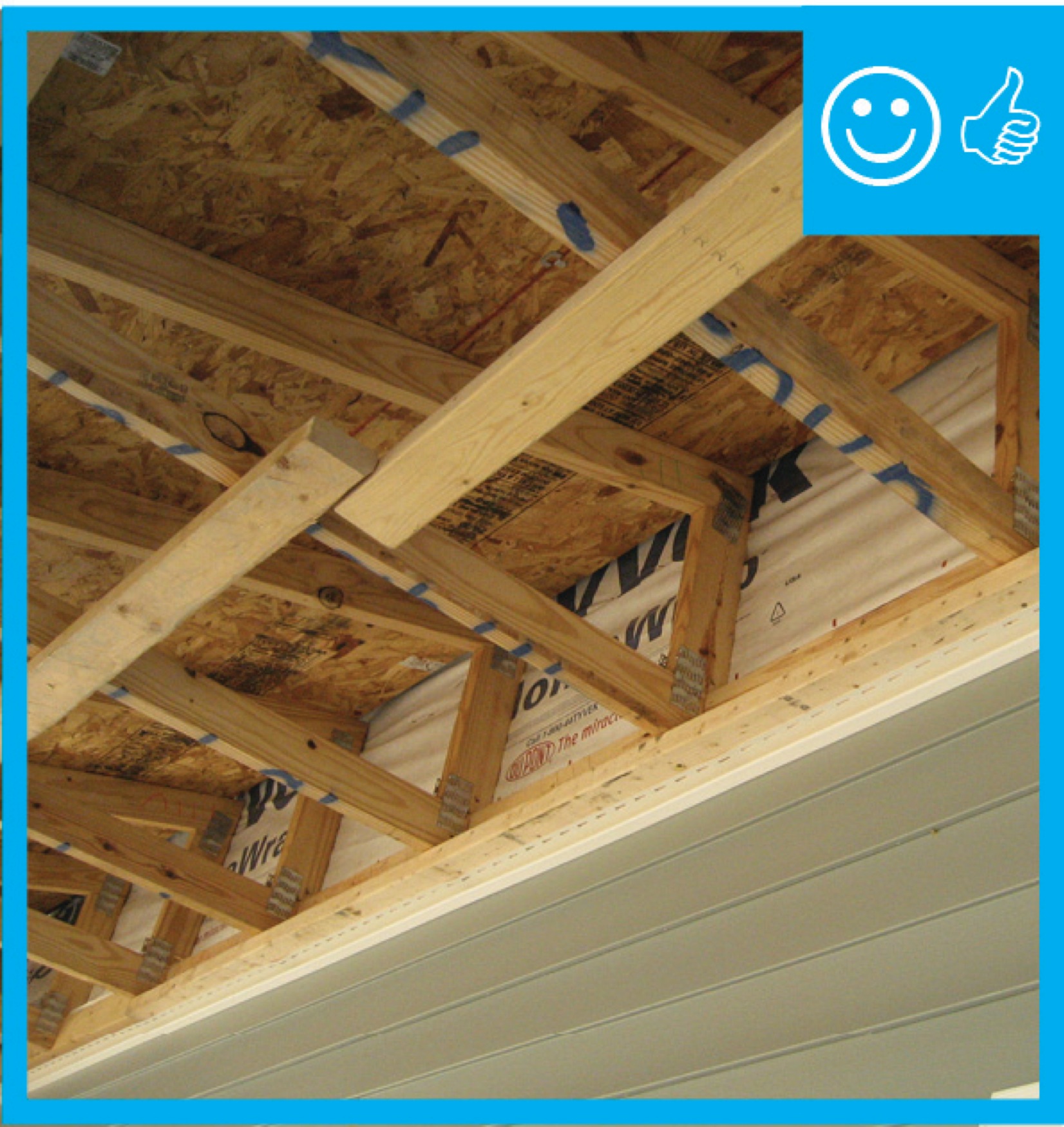
Framing is sequenced to install an air barrier of OSB, plywood, or rigid foam between the porch and the attic.
Image
Image
Horizontal furring strips are installed over a taped smart membrane that serves as an air and vapor barrier and holds in insulation; the furring strips will provide a nailing surface for tongue-and-groove wood porch ceiling cladding.
Image

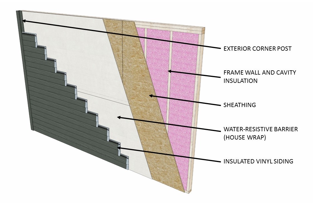
House wrap is sealed at all seams and overlaps flashing to serve as a continuous drainage plane over the exterior walls.
Image
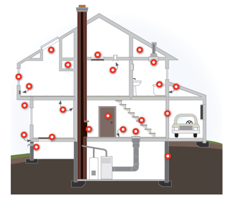
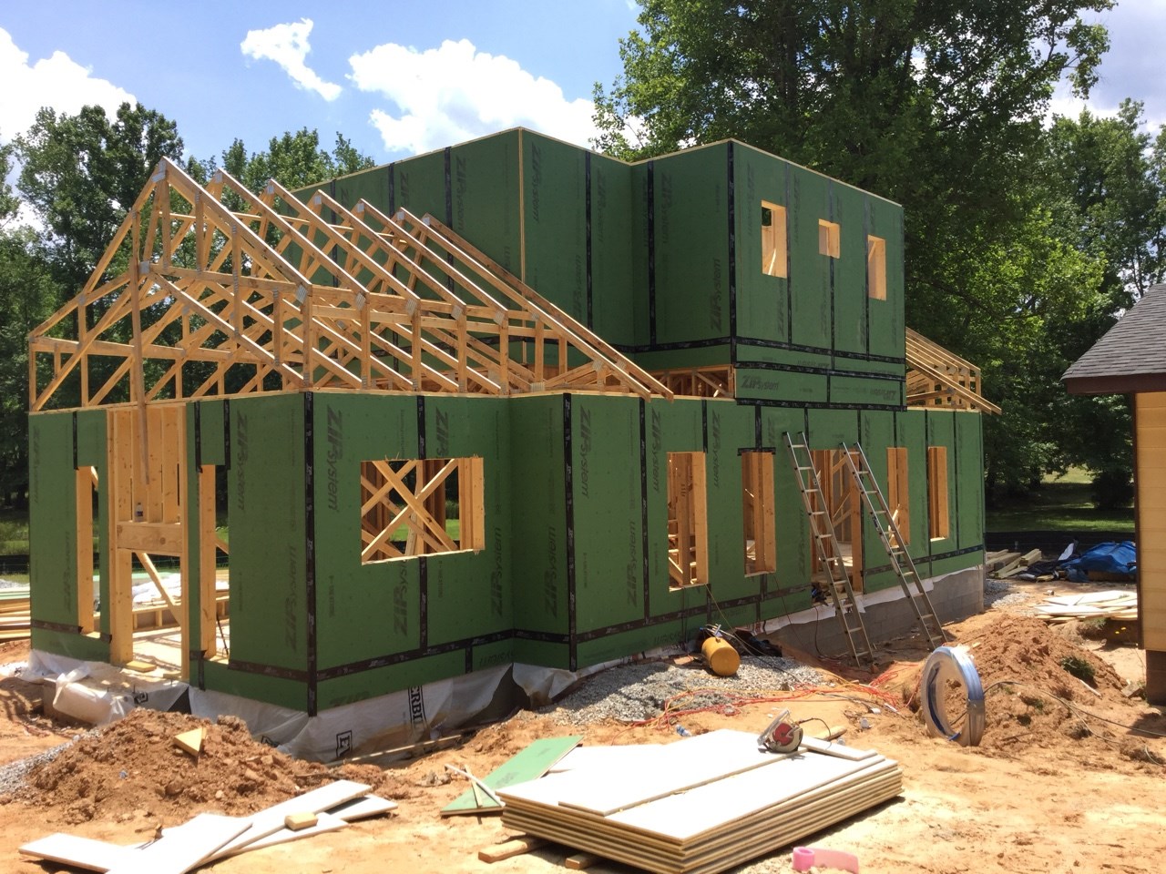
Identify what materials will constitute the continuous air barrier around the building envelope.
Image
Image
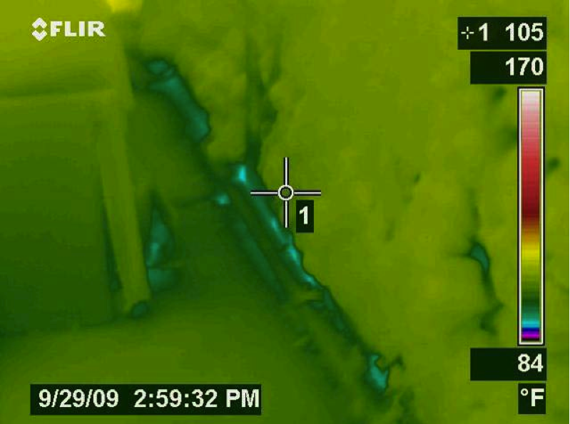
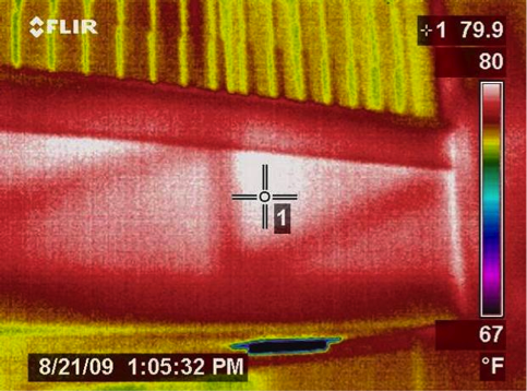
Infrared imaging shows cold conditioned air pouring out of the open floor cavities under this attic kneewall into the hot unconditioned attic
Image
Image
Image
Install a continuous air barrier below or above ceiling insulation and install wind baffles.
Image
Install a rigid air barrier to separate the porch attic from the conditioned space.
Image
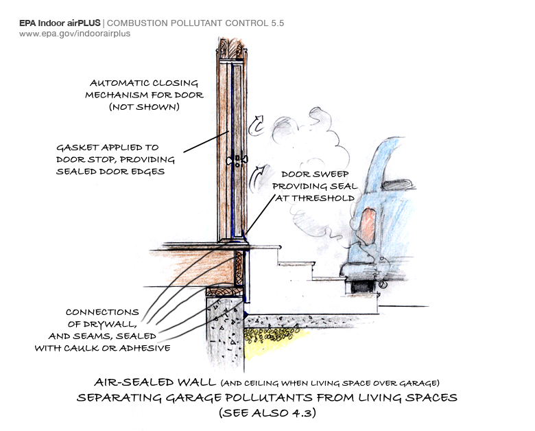
Install a self-closing door with weatherstripping and thoroughly air-seal the shared house-garage walls to help keep automobile exhaust and other pollutants out of the home.
Image
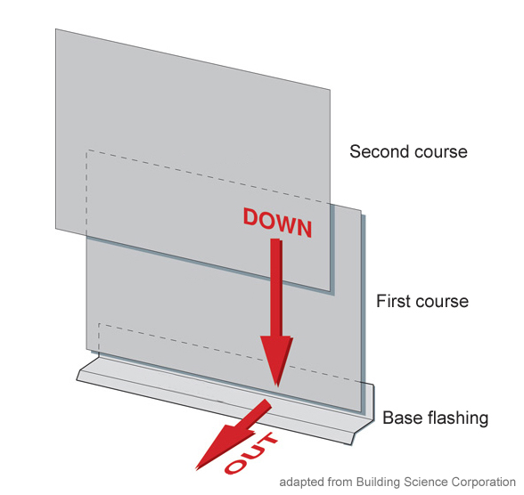
Install all layers of the drainage plane to overlap, not underlap, to direct bulk water down and out of the wall.
Image
Image
Image
Image
Image
Image
Image
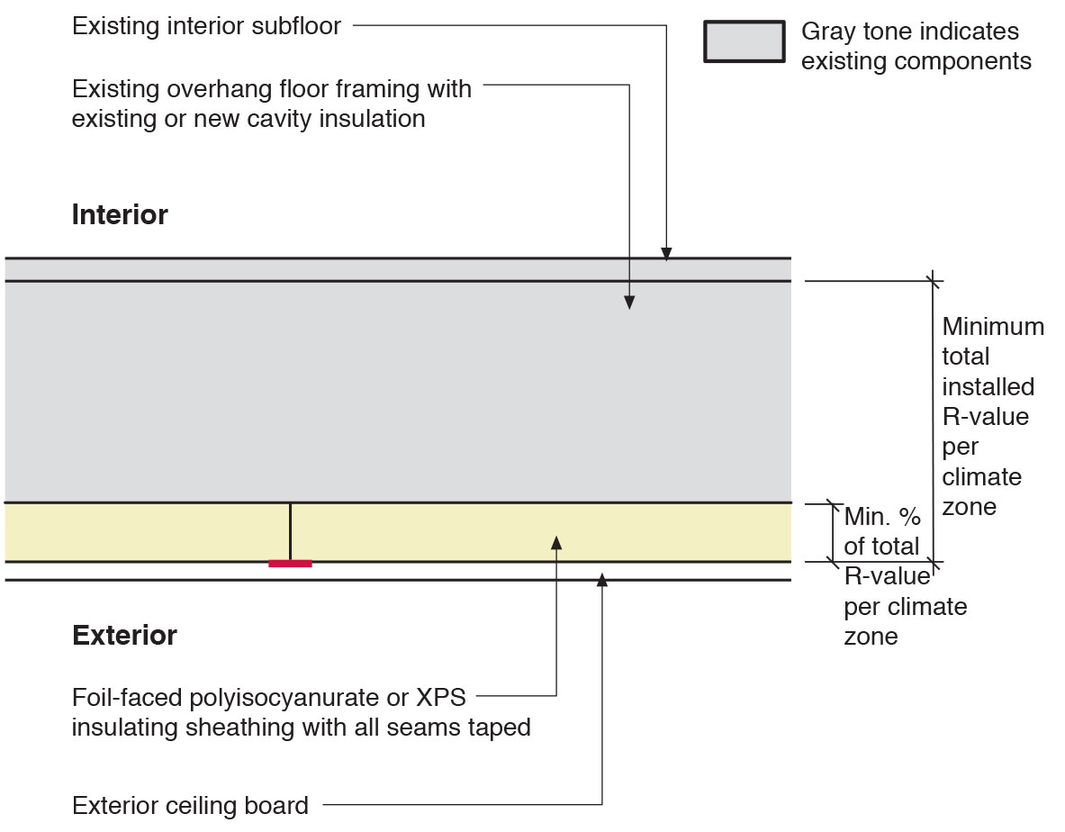
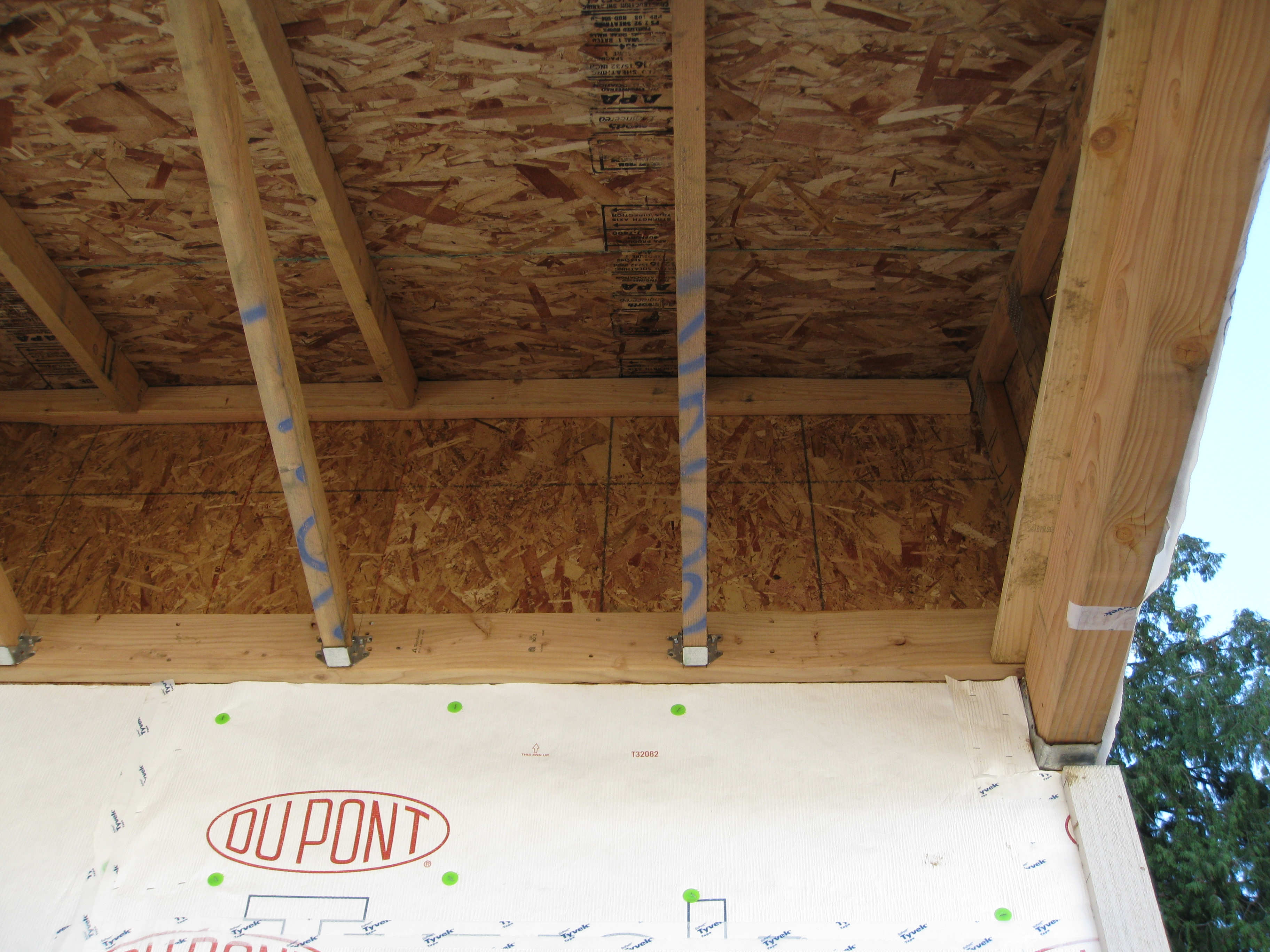
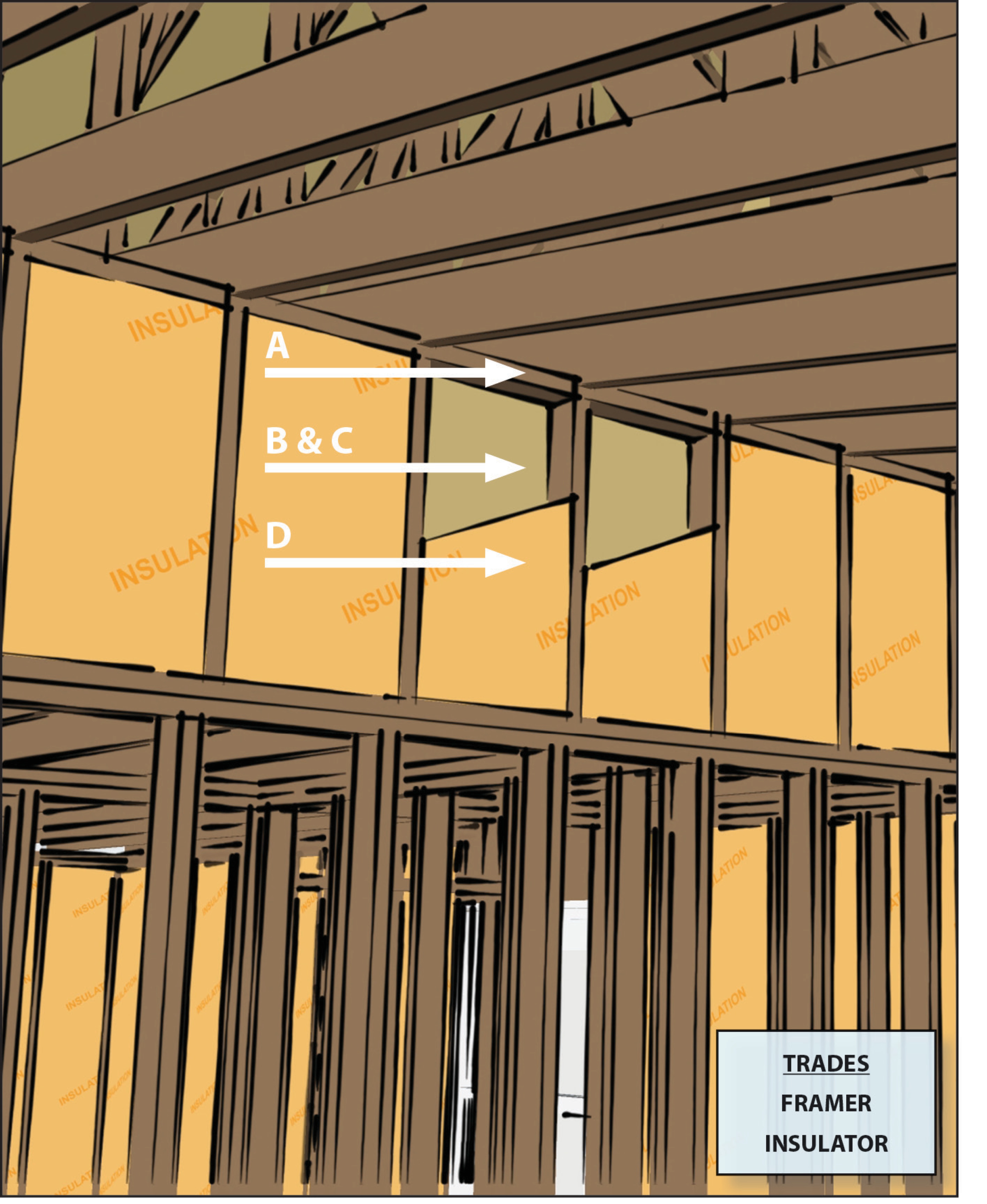
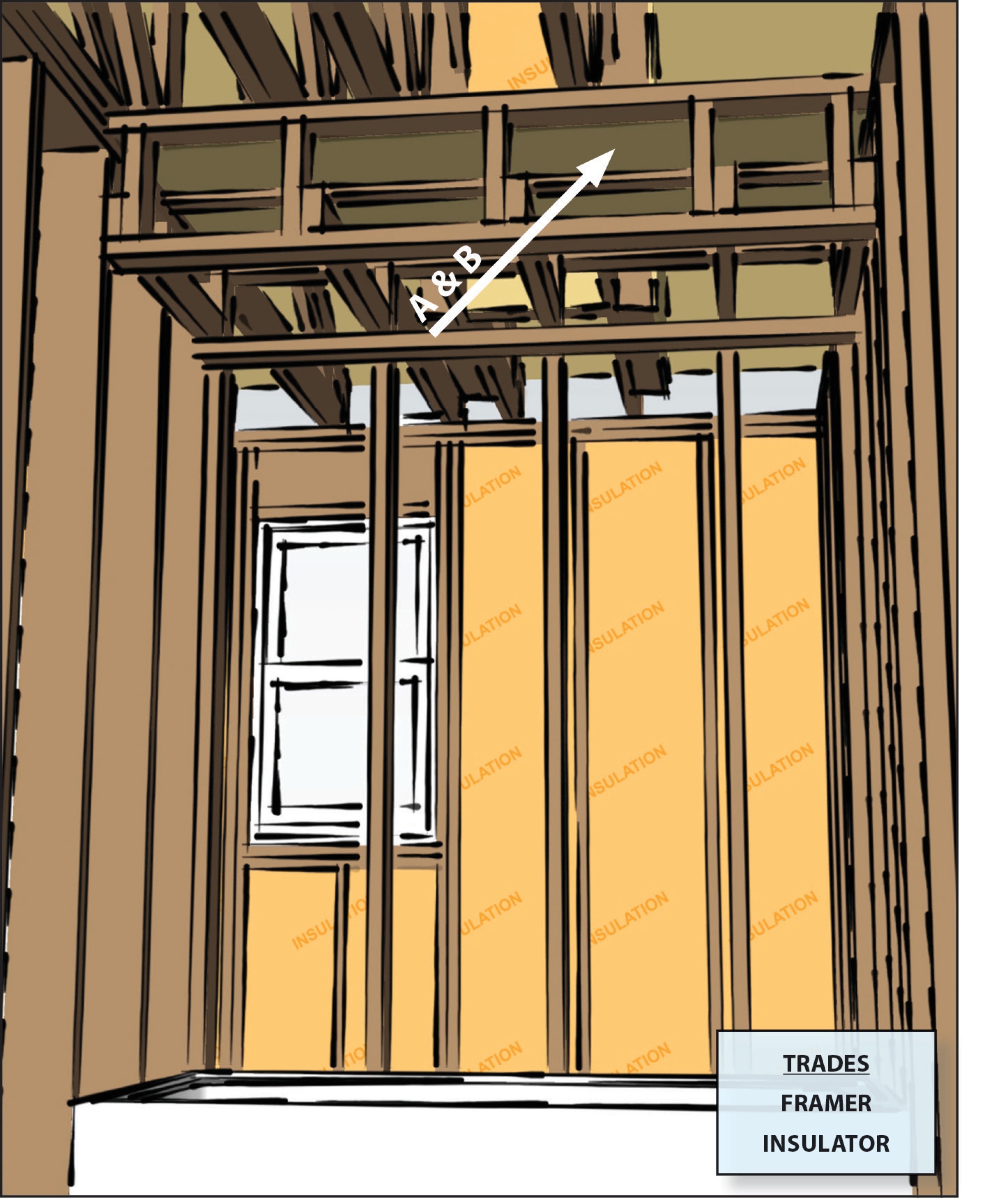
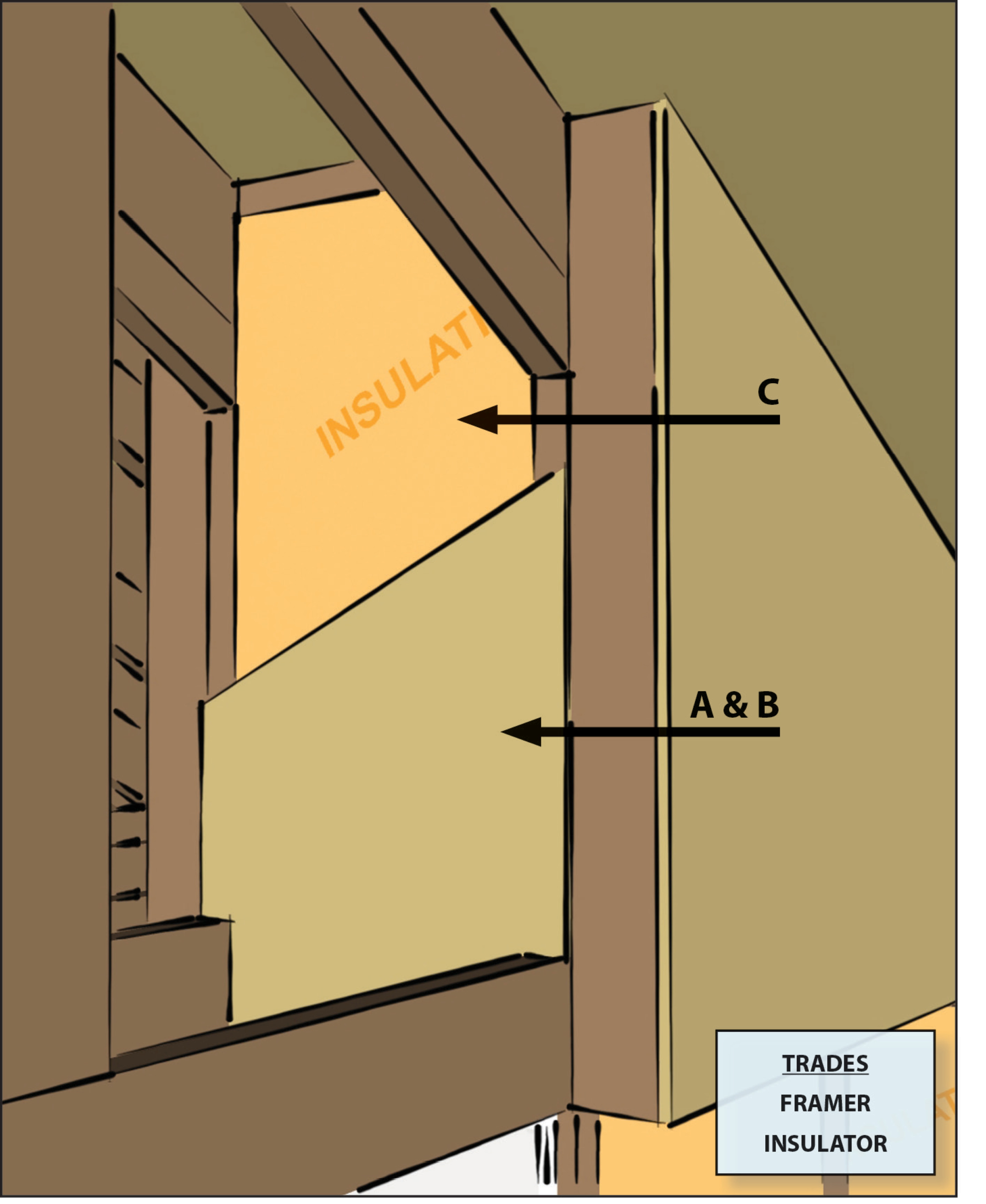
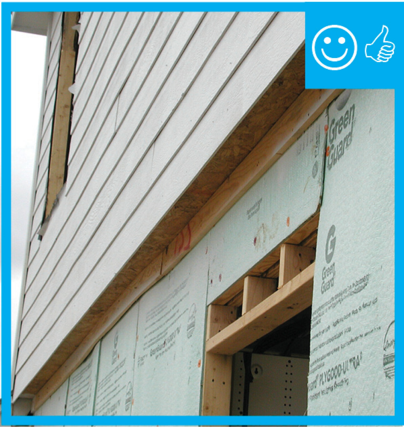
Install rigid insulation and finish material below the framing and cavity insulation of a building overhang
Image

Image
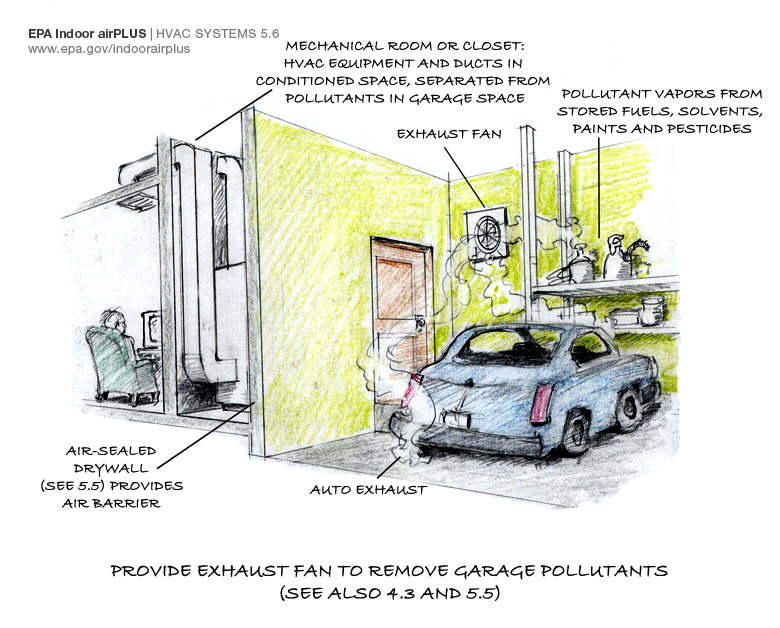
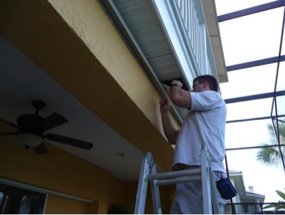
Installing a garage exhaust fan is one important step in keeping auto exhaust and other pollutants out of the home
Image
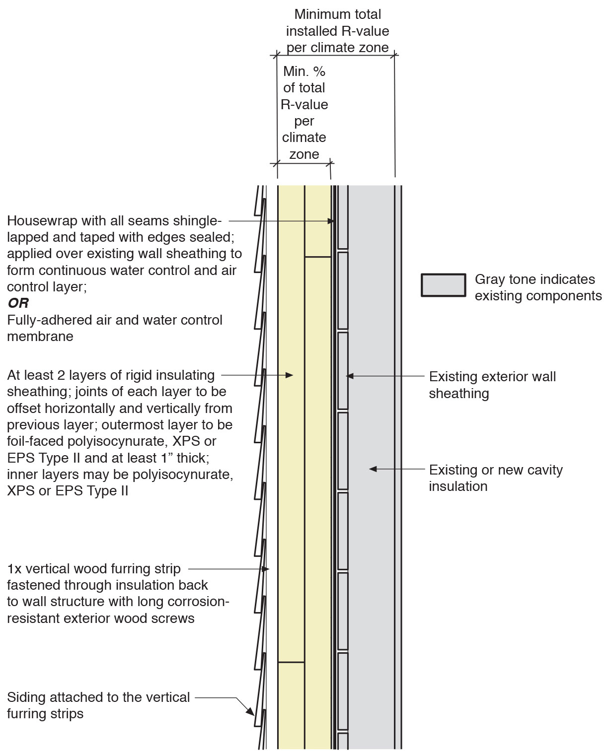
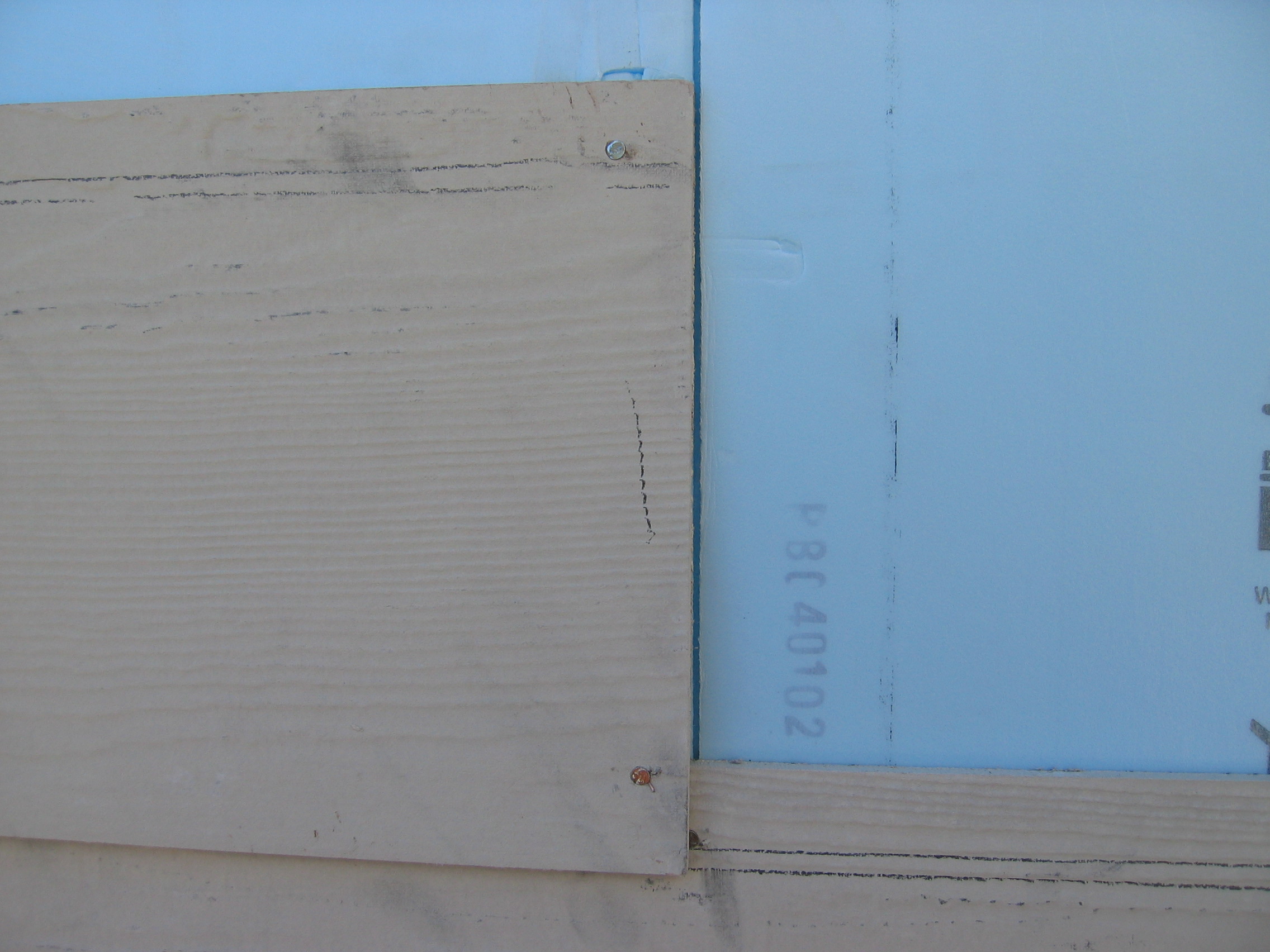
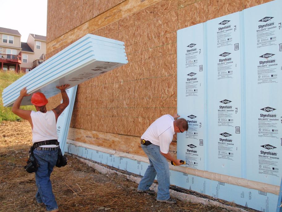
Insulating sheathing is installed on exterior of an existing framed wall with water control between existing sheathing and insulating sheathing
Image
Image
Image

Limited attic access can make inspections for missing air barriers and insulation challenging
Image
Limited attic access may make it necessary to use a bore scope when inspecting for missing air barriers and insulation in existing buildings.
Image
Image
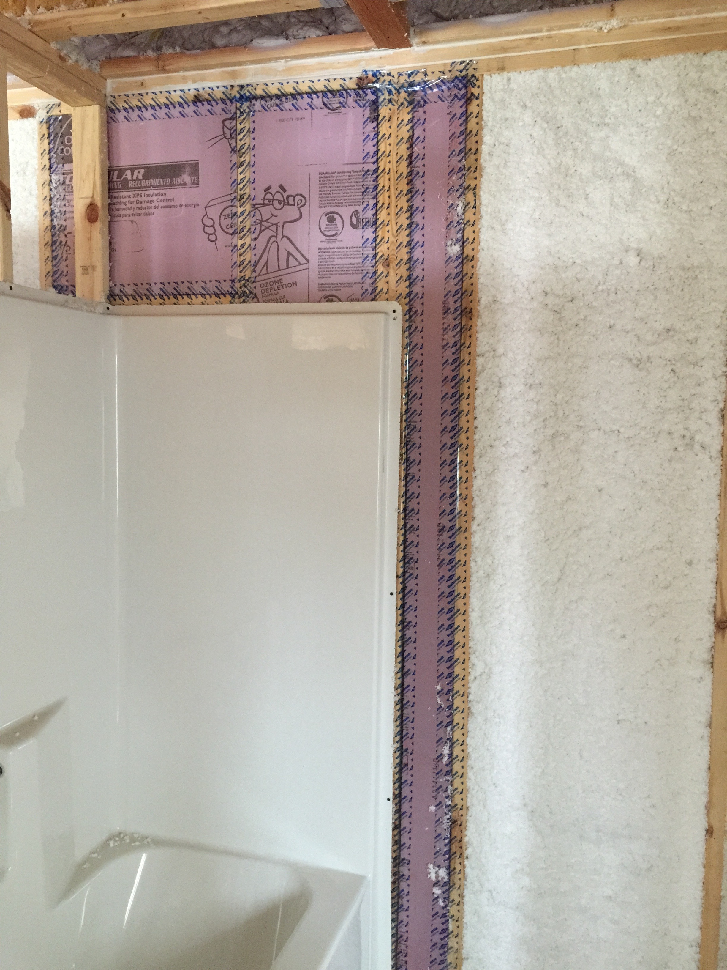
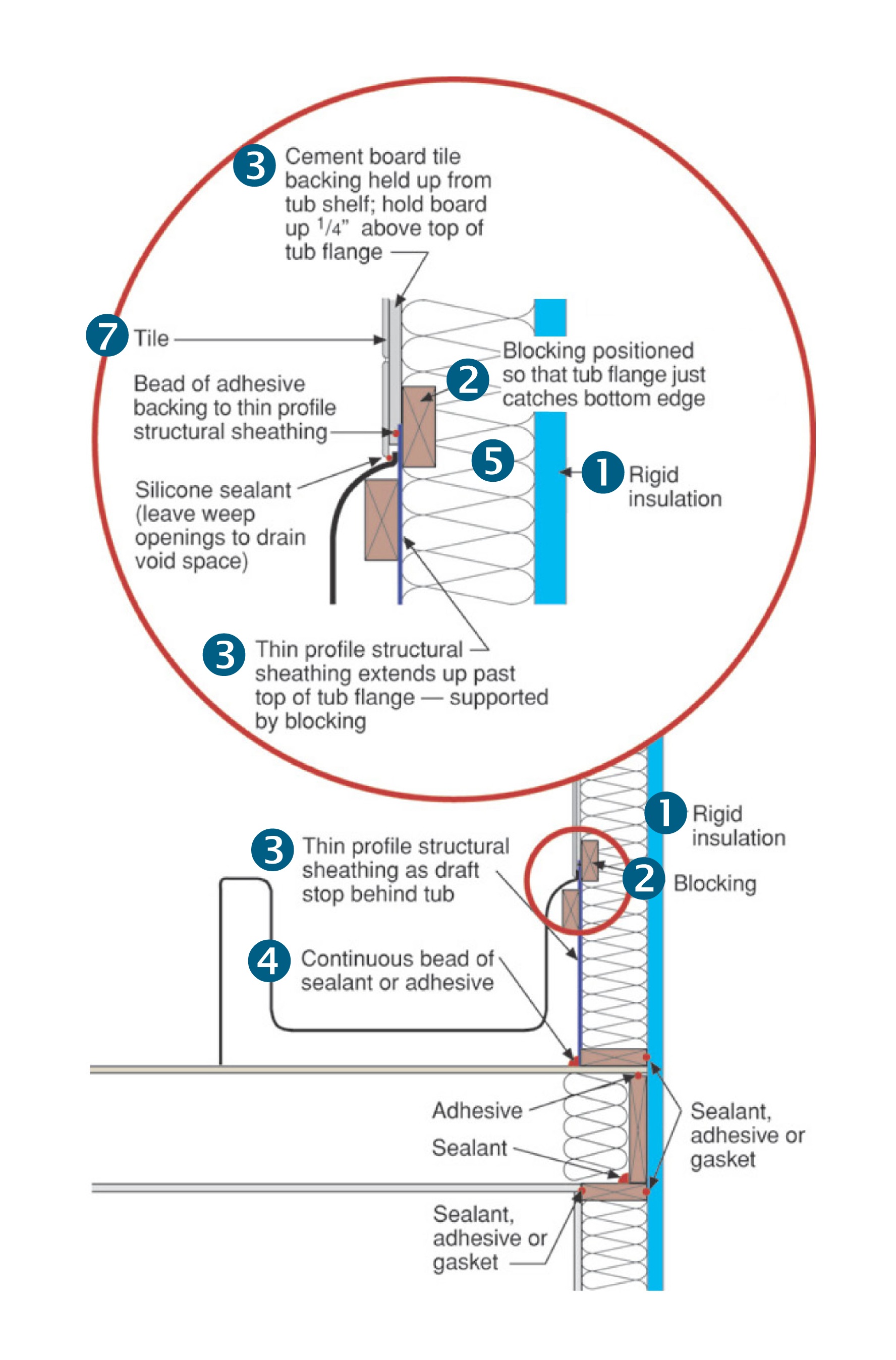
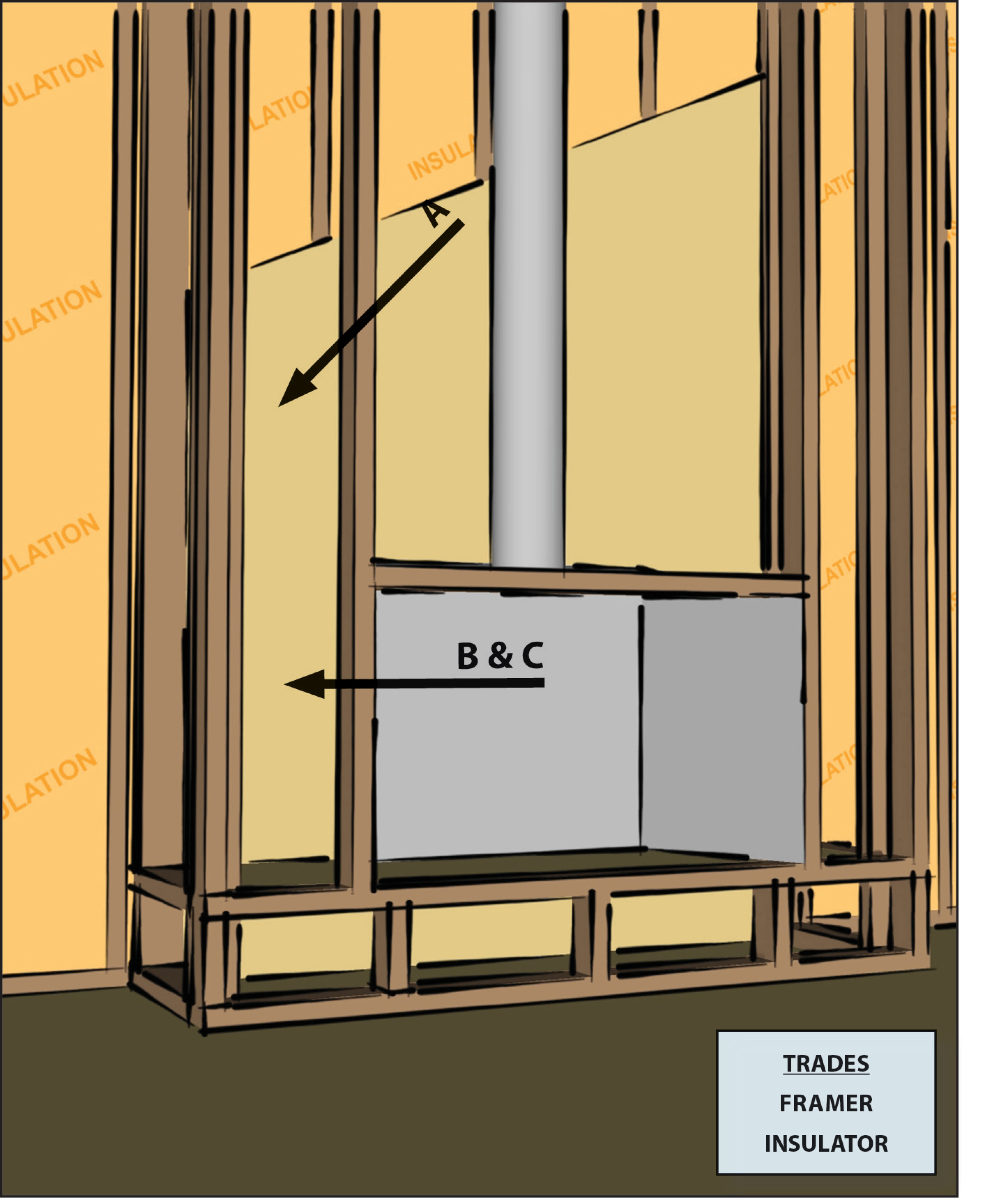
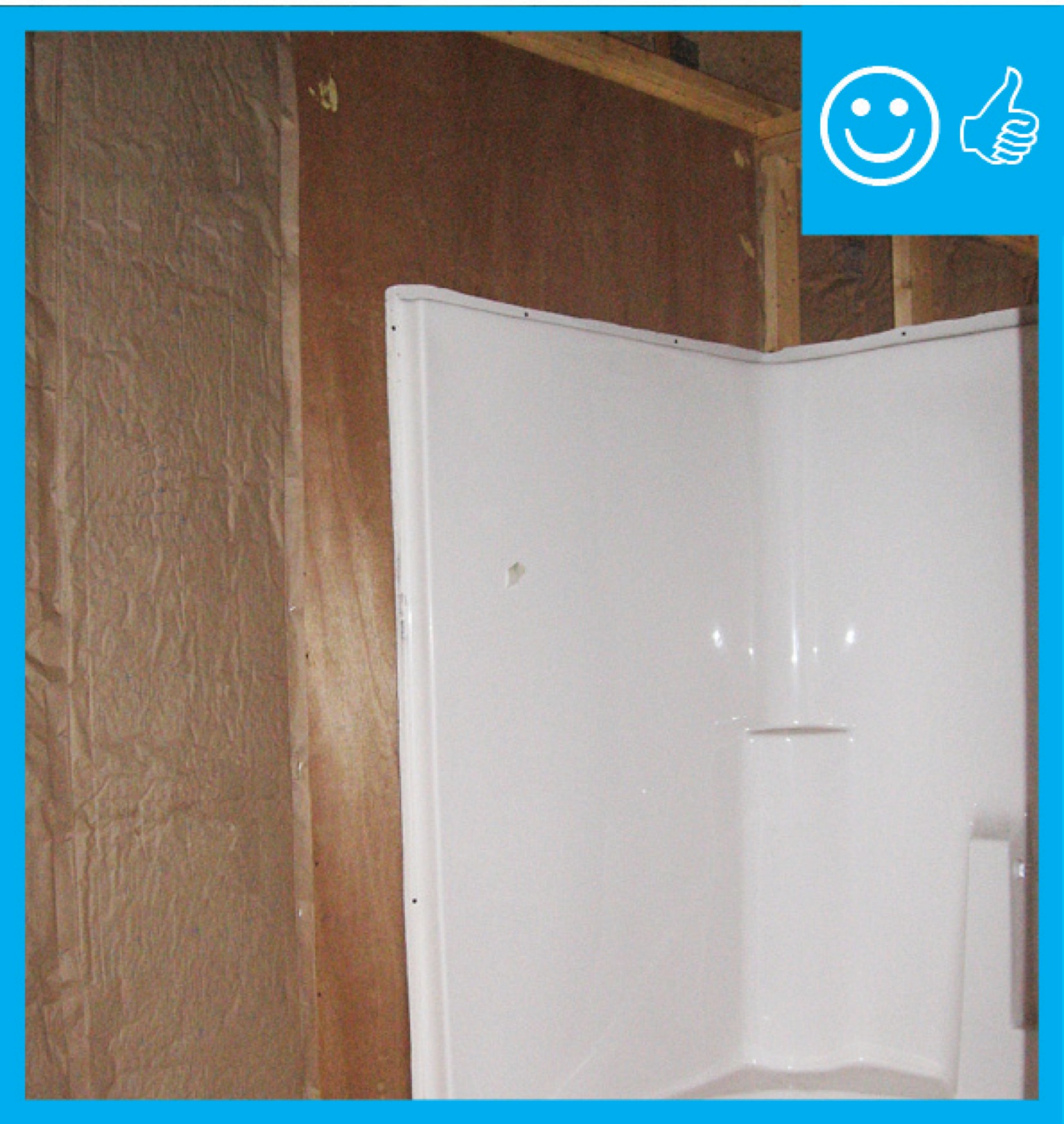
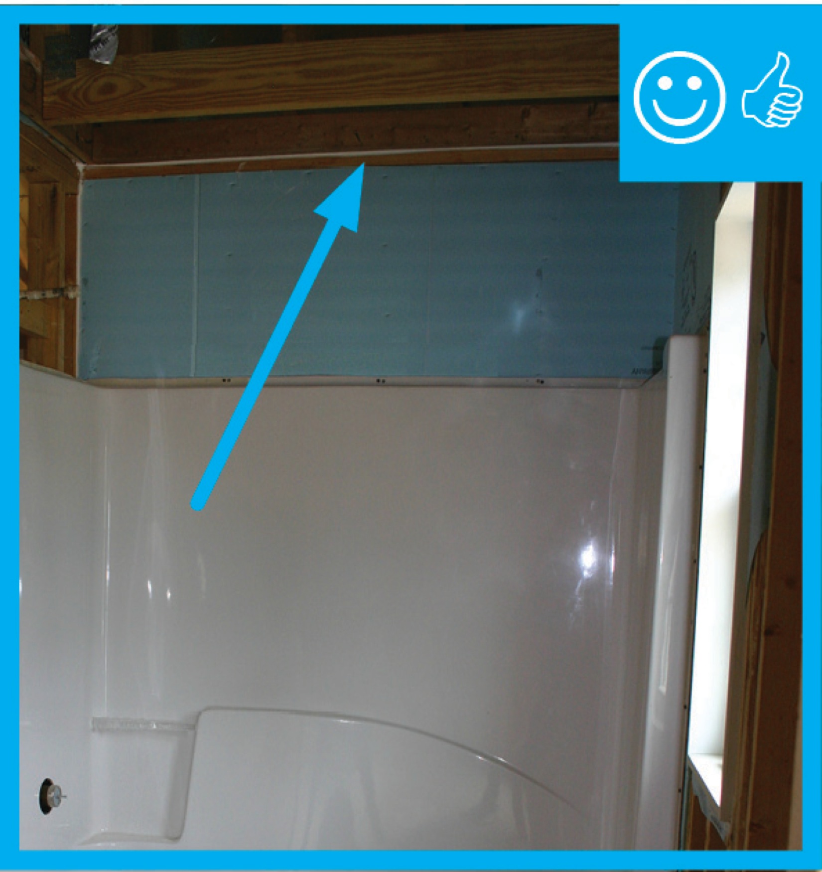
Moisture-resistant rigid foam insulation was installed to provide a continuous air and thermal barrier behind the tub-shower insert.
Image
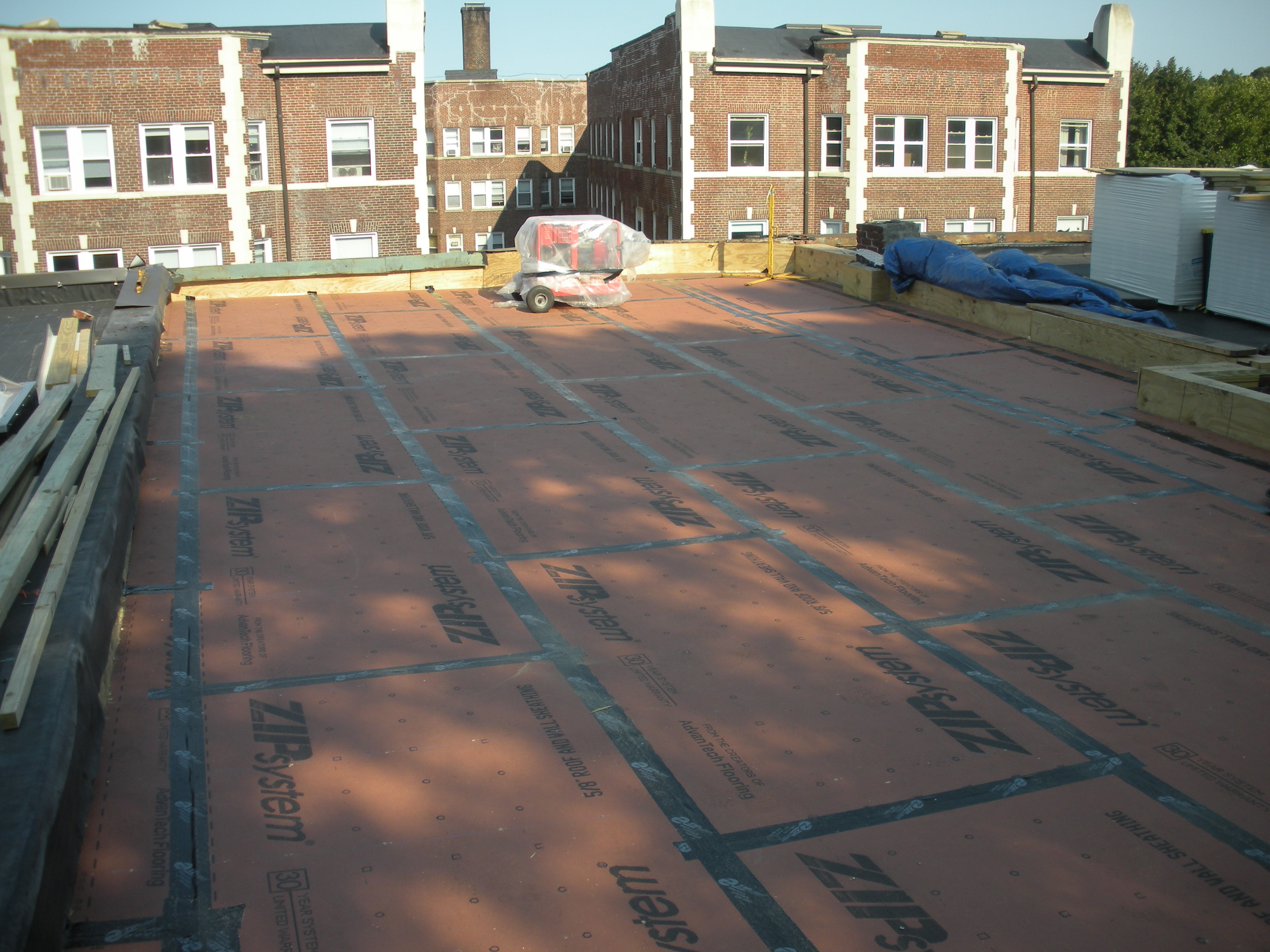
New coated OSB roof sheathing is installed over the existing sheathing of the flat roof and taped at the seams to provide a continuous air barrier
Image

Image
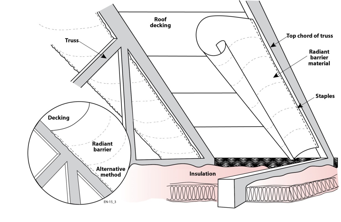
Radiant barrier sheeting can be stapled to the underside of the rafters or along the inside edge of the rafters
Image

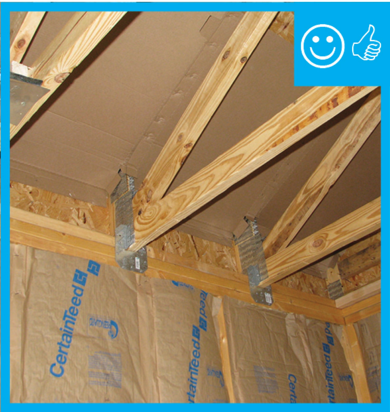
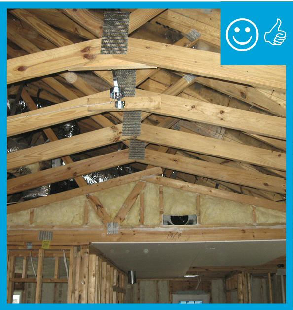
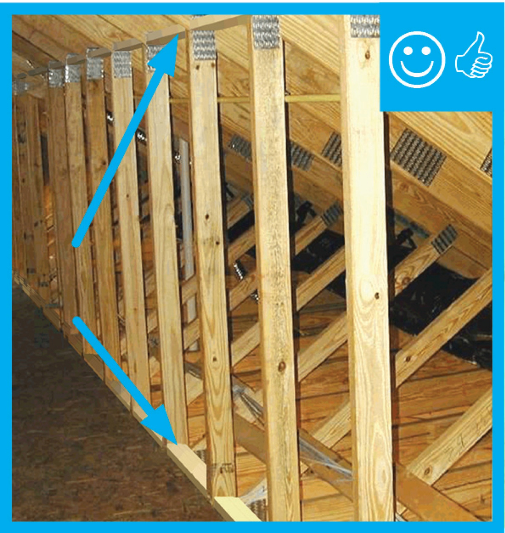
Raised heel energy trusses extend past the exterior wall and are deeper at the wall allowing room for full insulation coverage over the top plate of the exterior walls.
Image
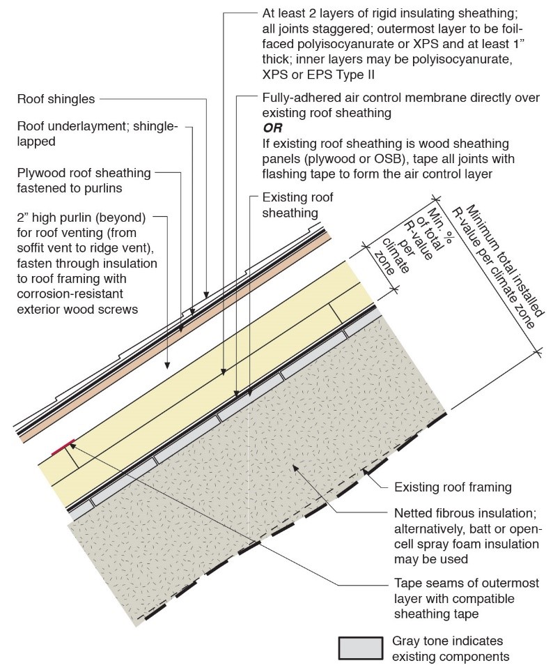
Retrofit an existing roof by installing rigid foam above the roof deck with a ventilation space between the rigid foam and the new roof sheathing plus new moisture and air control layers and cavity insulation in the roof rafters.
Image
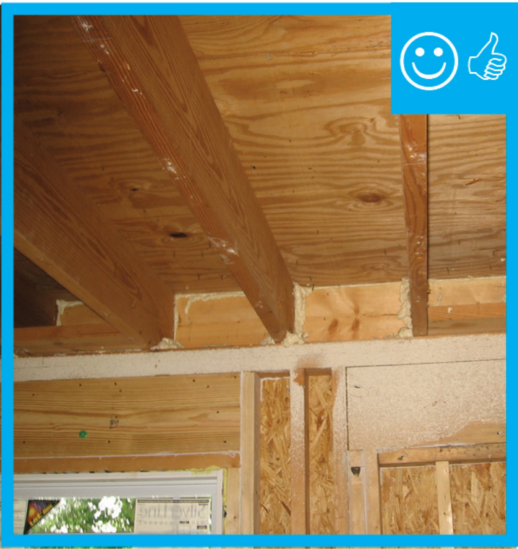
Right - A “flash” seal approach with spray foam provides a continuous air barrier between the ceiling and walls of the garage and the living space.
Image
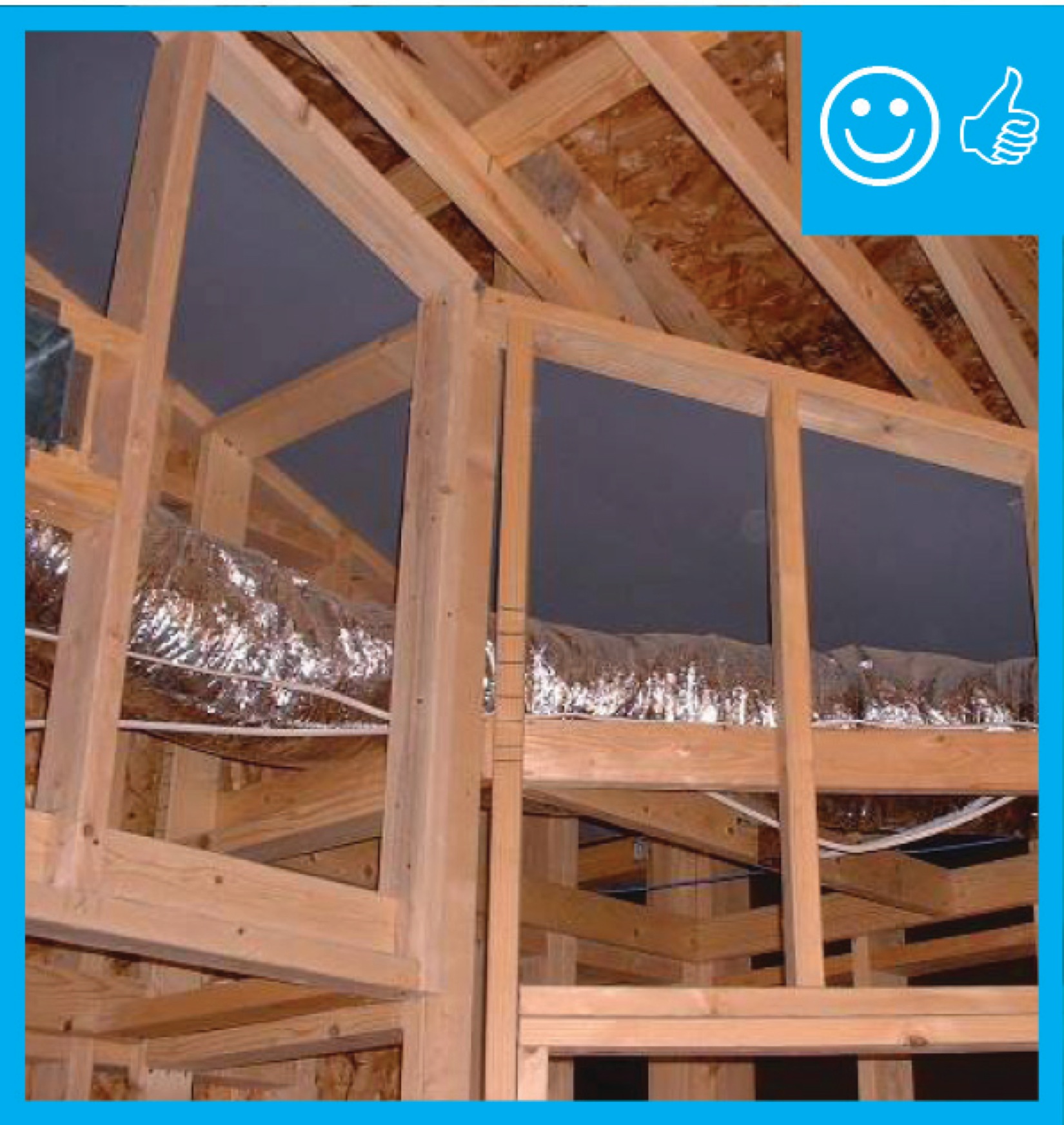
Right - a dropped ceiling below a taped plywood air barrier provides a service cavity for ducts and wiring.
Image
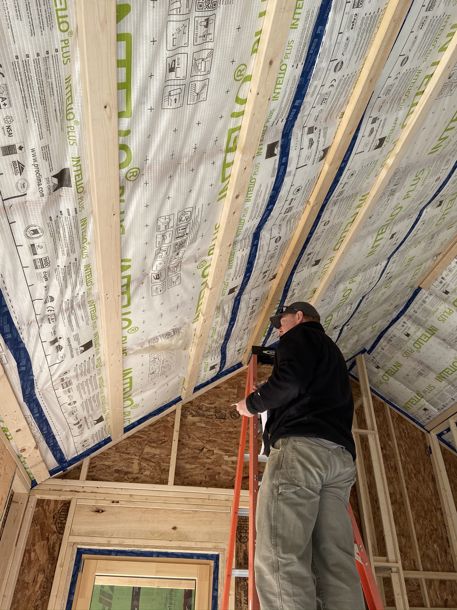
Right - A smart vapor barrier wraps the walls and window frames of this home. Seams are taped to provide an air- and water-resistant barrier.
Image
Right - Air barrier is present and installed between the floor system and unconditioned space.
Image
Image
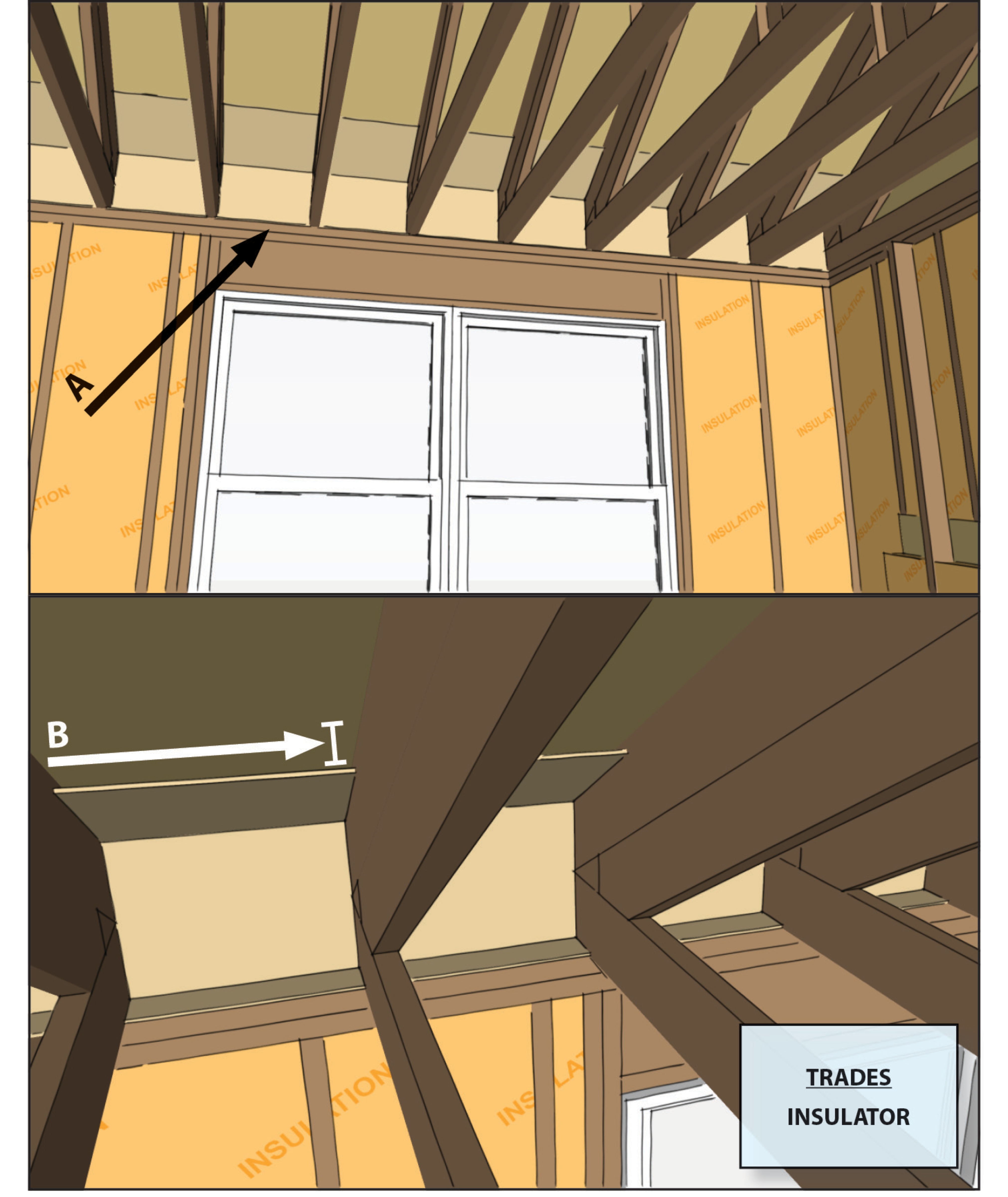
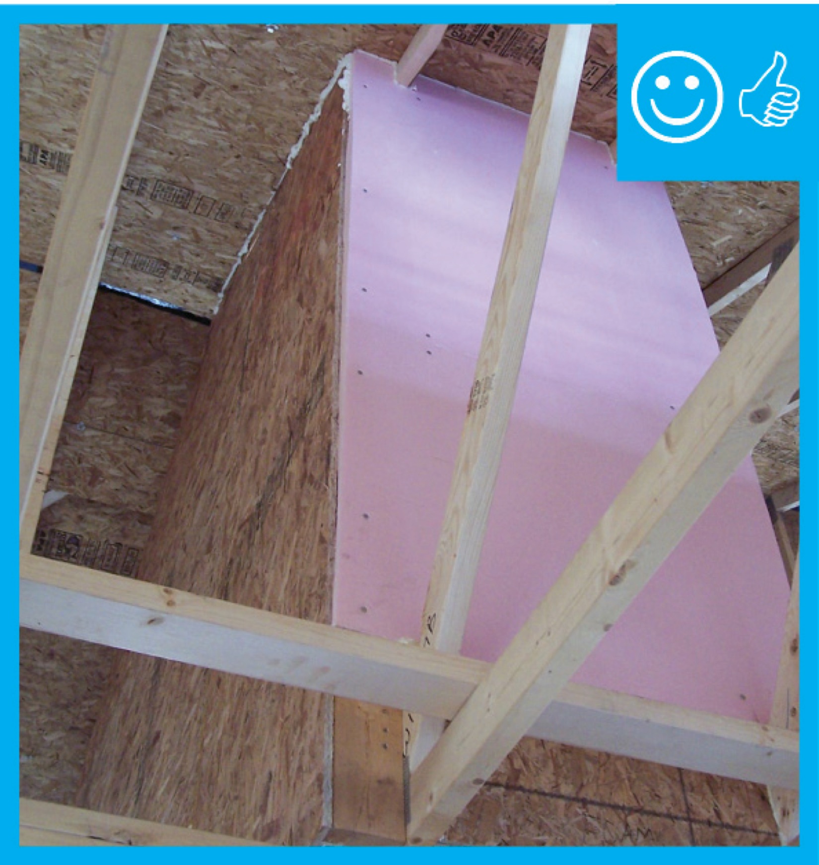
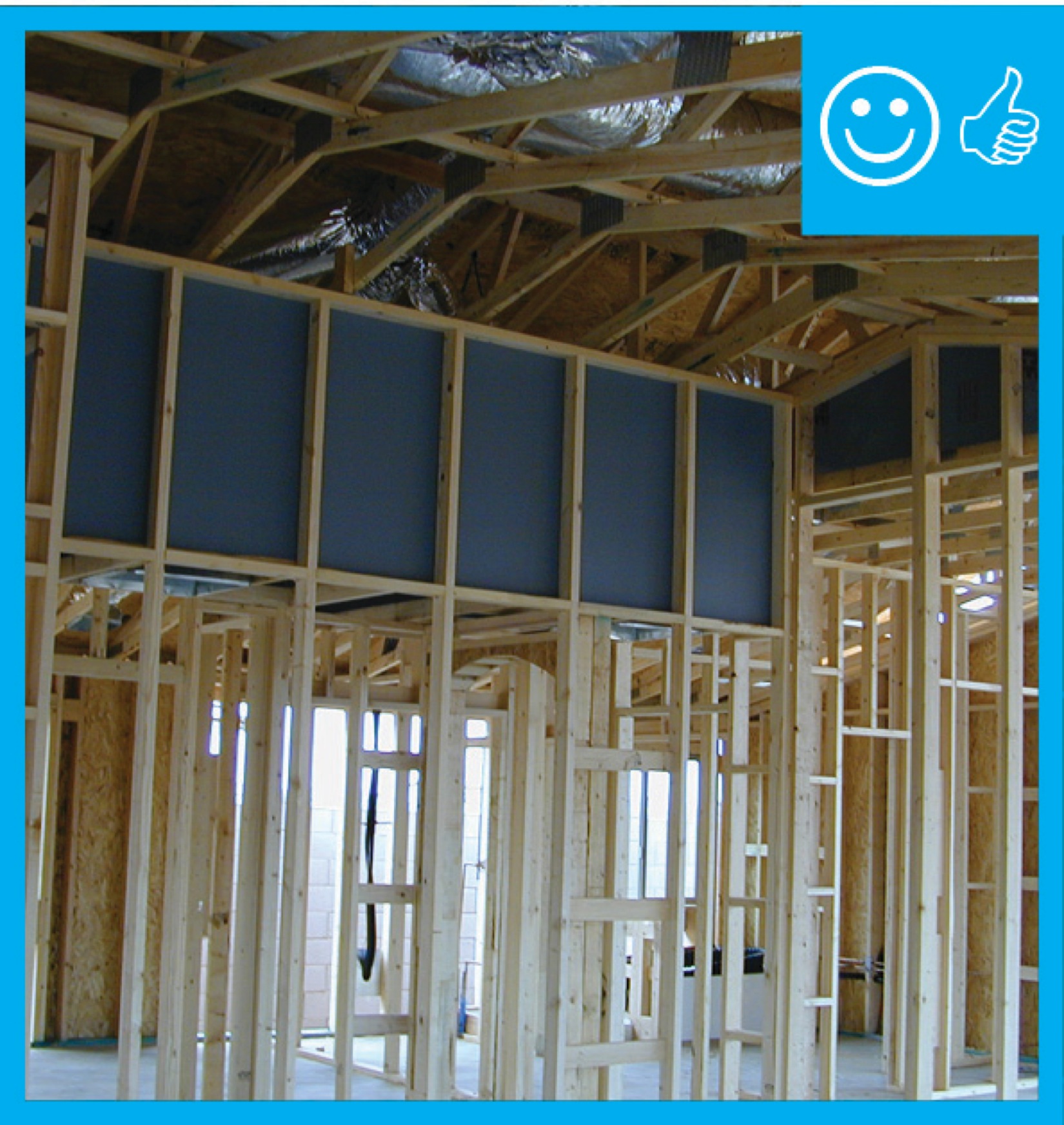
Right - Air barrier is present between the dropped ceiling/soffit and the attic.
Image
Right - Air barrier is present between the dropped ceiling/soffit and the attic.
Image
Image
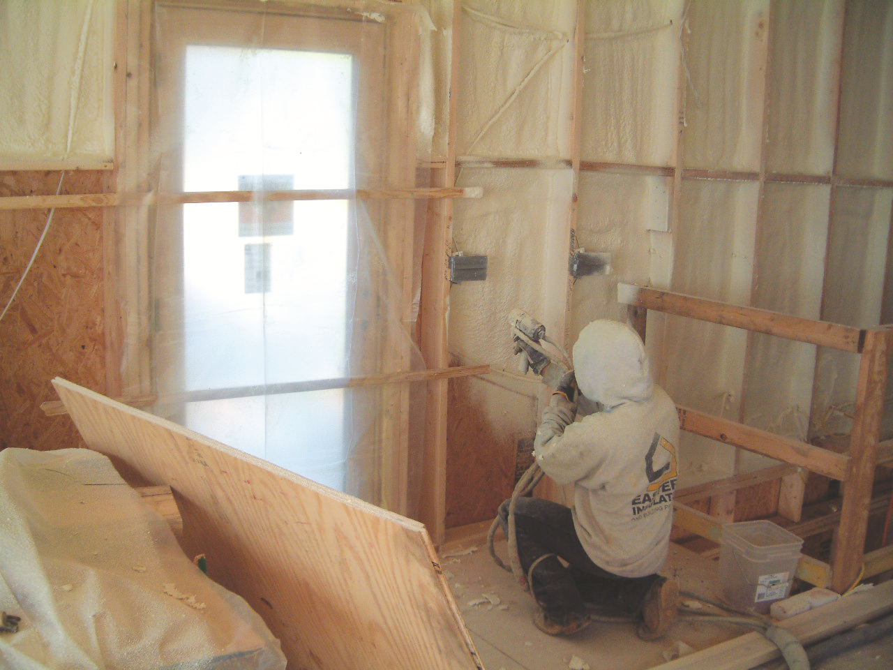
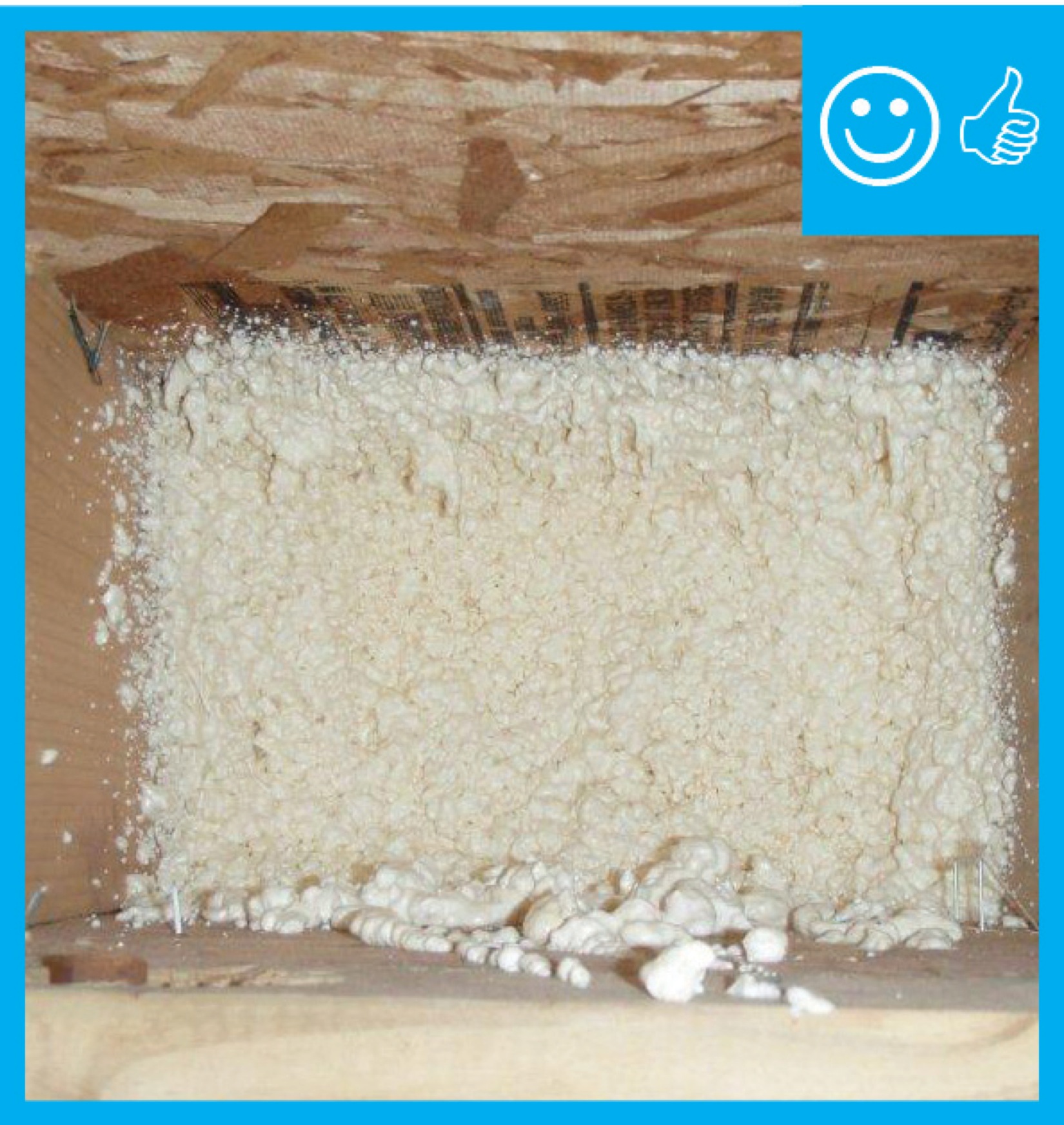
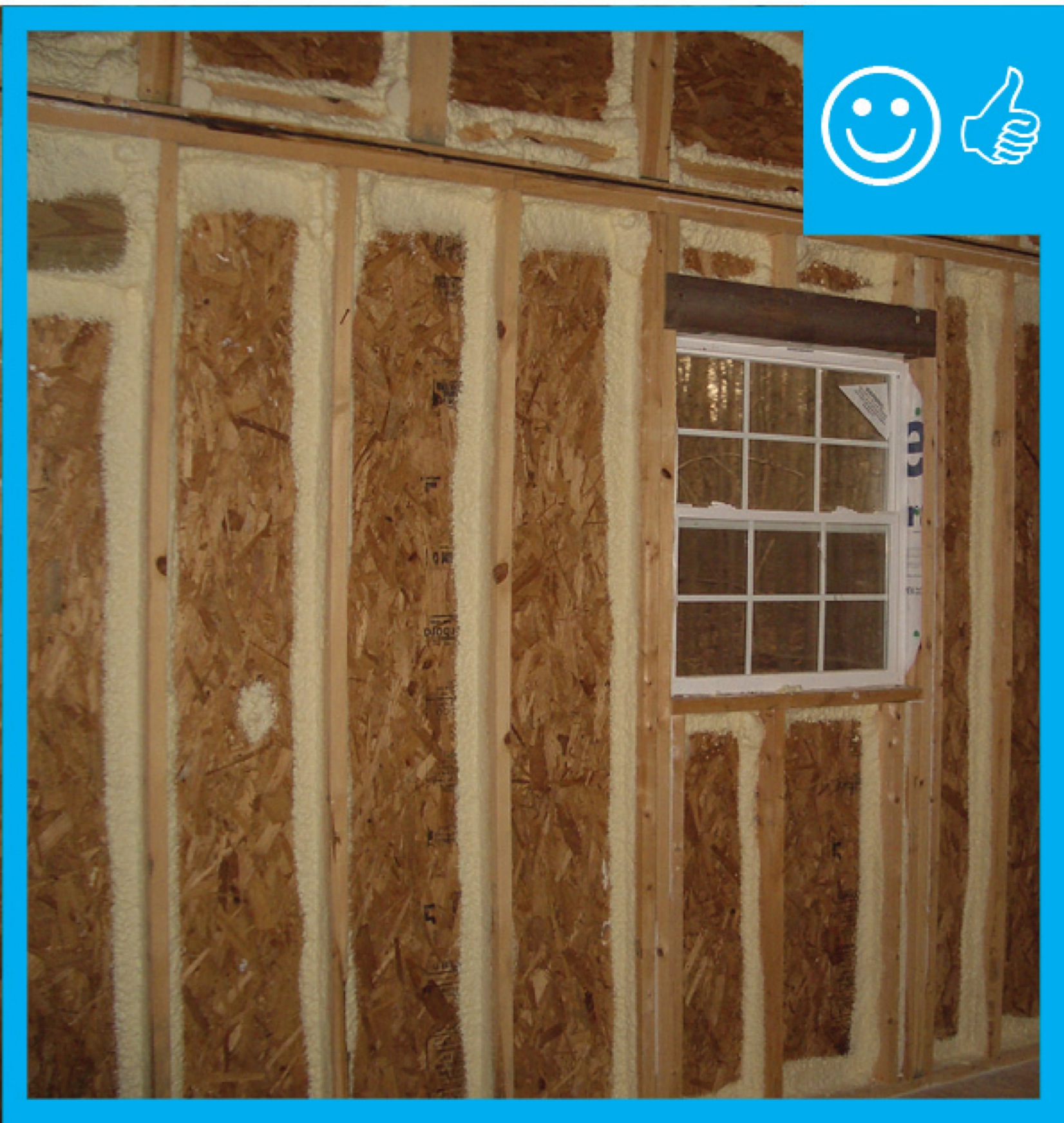
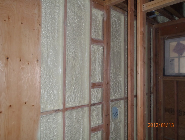
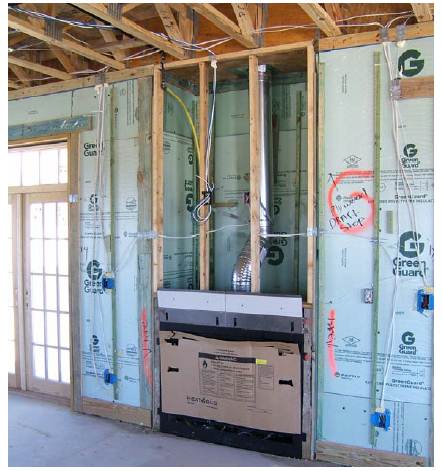
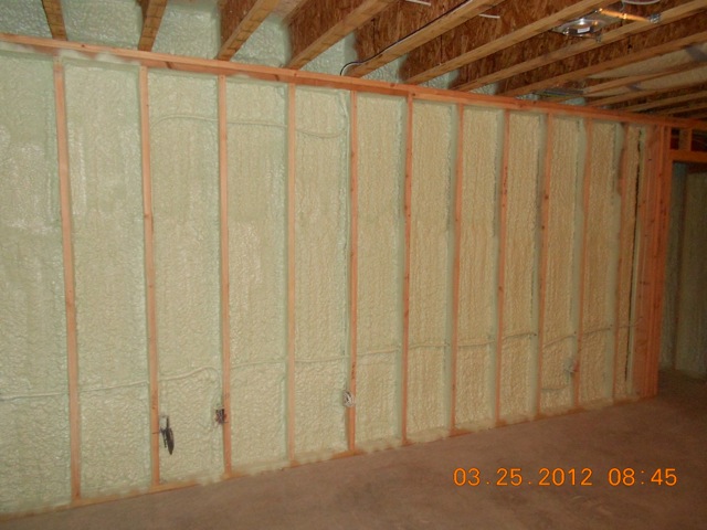
Right - Closed-cell spray foam is installed as a skim coat to provide air tightness to an exterior wall cavity before installing batt or blown cavity insulation.
Image
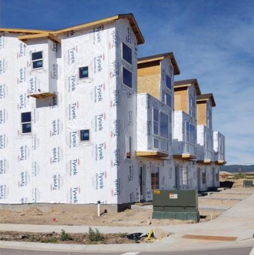
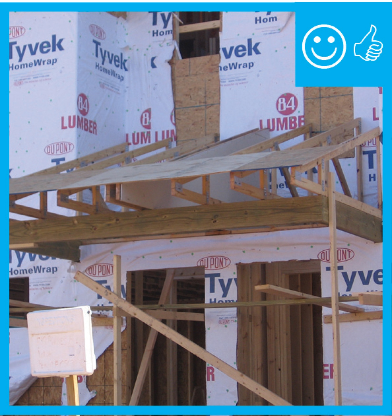
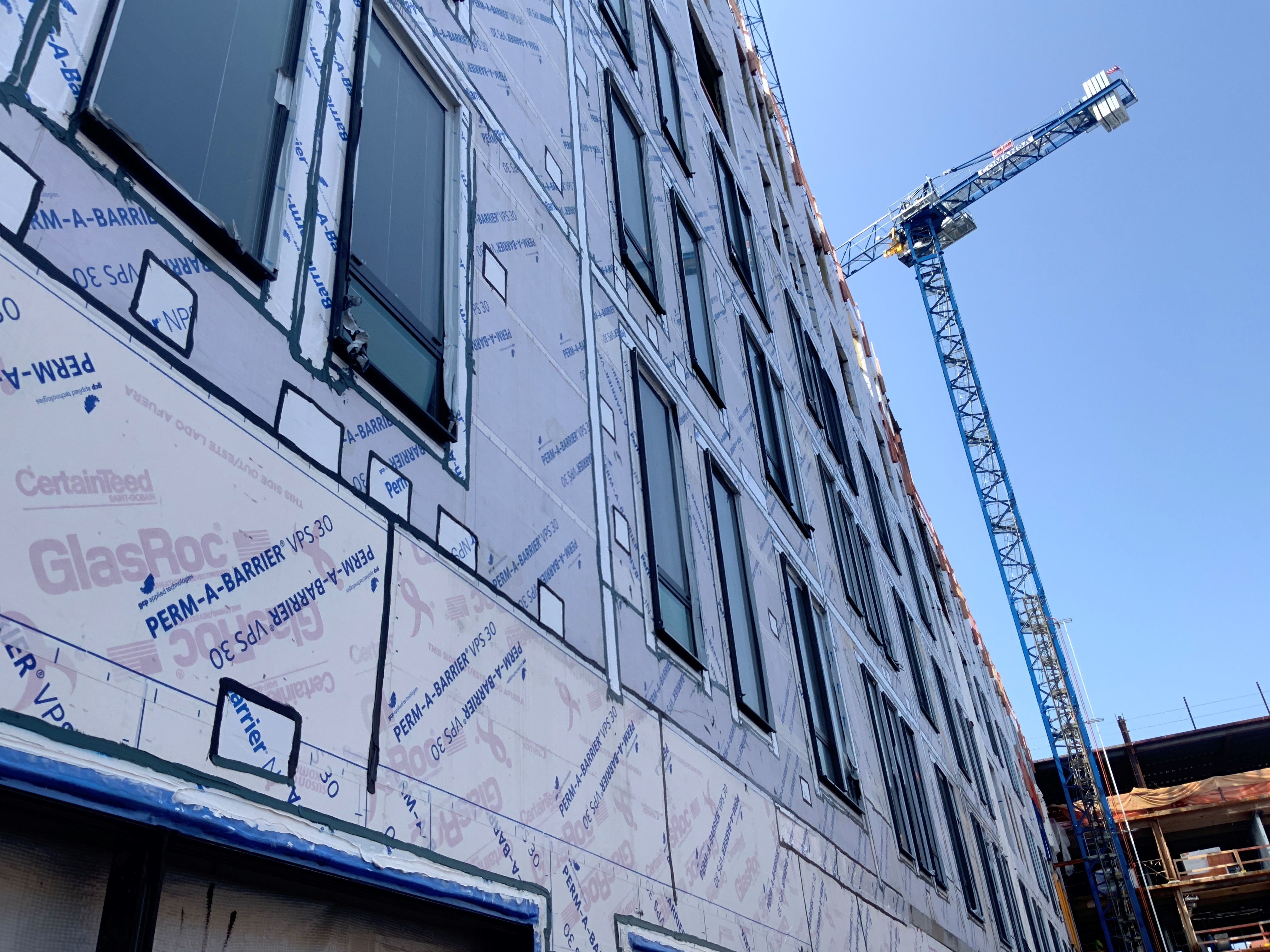
Right - House wrap is carefully installed from the top of the roof line to the foundation; seams are overlapped and taped to provide a continuous air- and weather-resistant barrier
Image

Right - House wrap is overlapped “shingle” style to direct moisture down and away from the house; seams will be taped so house wrap serves as both an air and weather barrier.
Image
Image
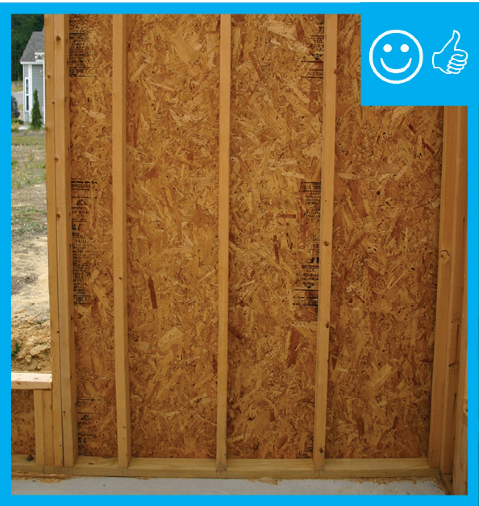
Right - Plywoood sheathing is taped at the seams to create a continuous air barrier that prevents air infiltration through critical junctures in the wall, such as at corners and between floors.
Image
Image
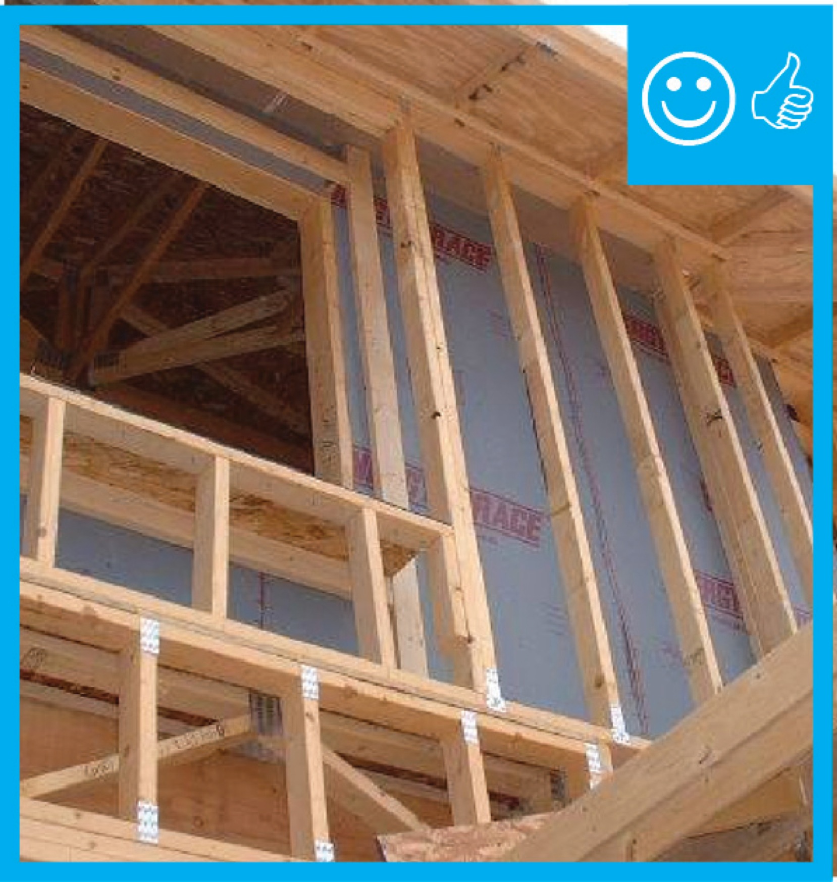
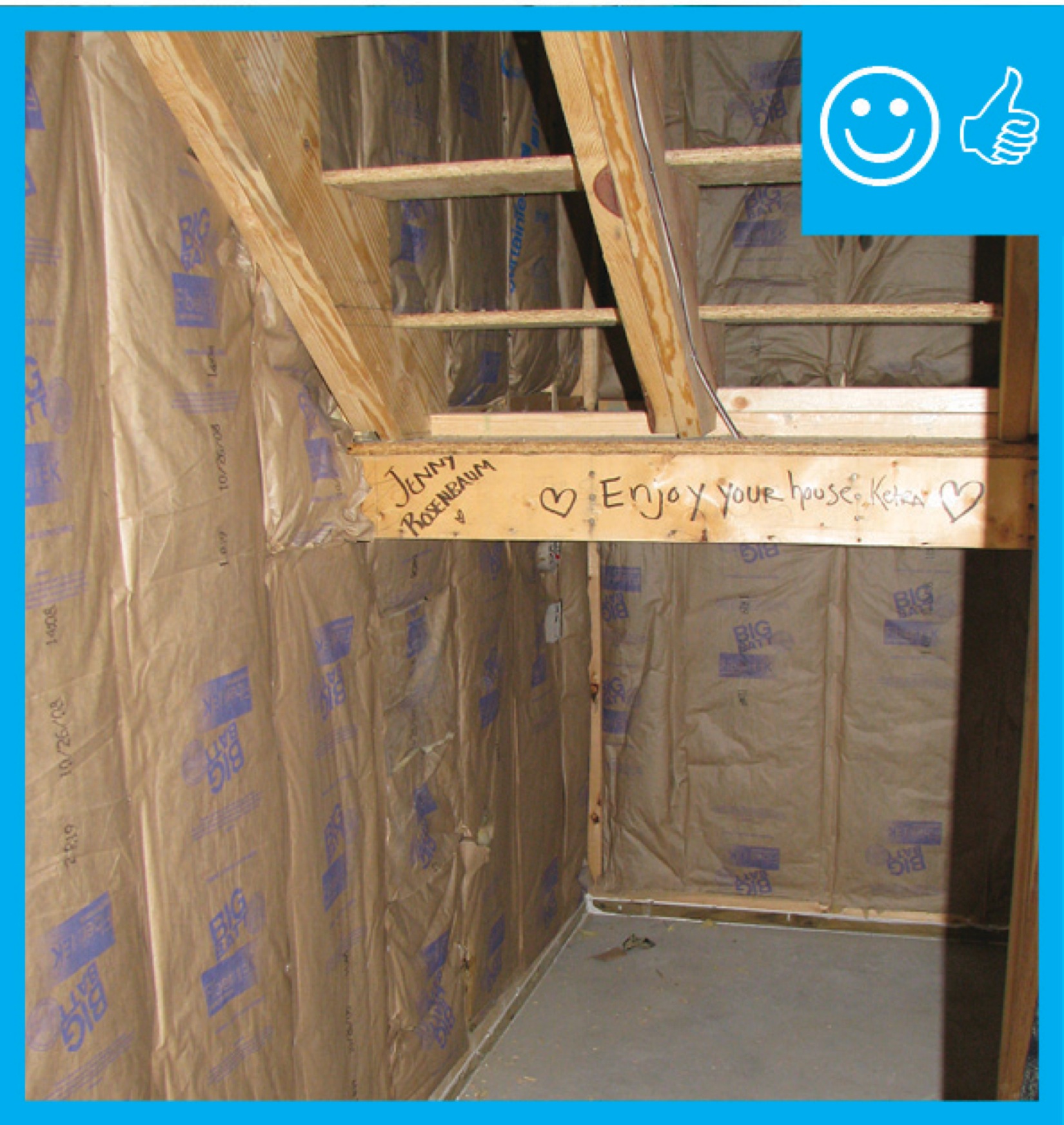
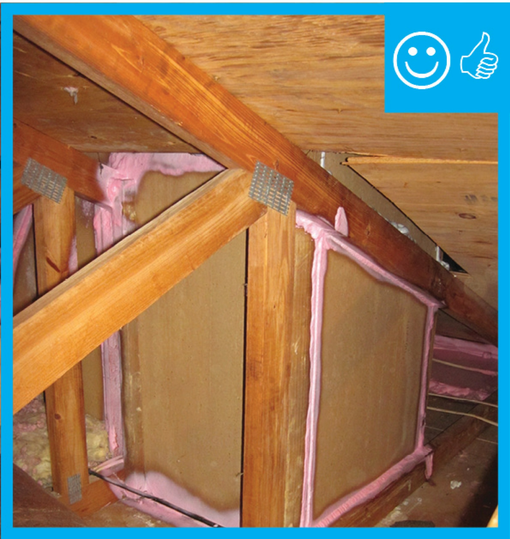
Right - These attic knee walls are insulated with rigid foam and sealed with spray foam to form a continuous air barrier at the gable end of this cathedral ceiling.
Image
Right - This cedar siding is installed over furring strips which allow an air and drainage gap behind the siding.
Image
Right - Walls and ceilings shared by the garage and living space must be air sealed and insulated.
Image
Right - Wind baffle installation will allow proper insulation depth over the top plate.
Image
Image
Image
Right – Air barrier and penetrations sealed between porch attic and conditioned space
Image
Image
Image
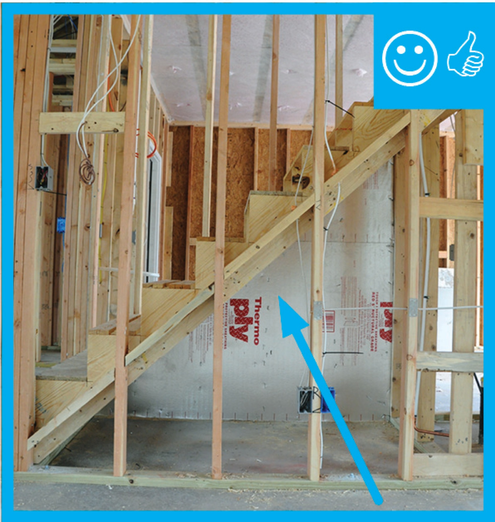
Right – Air barrier installed under staircase (picture taken from house looking into attached garage)
Image
Image
Image
Image
Image
Image
Image
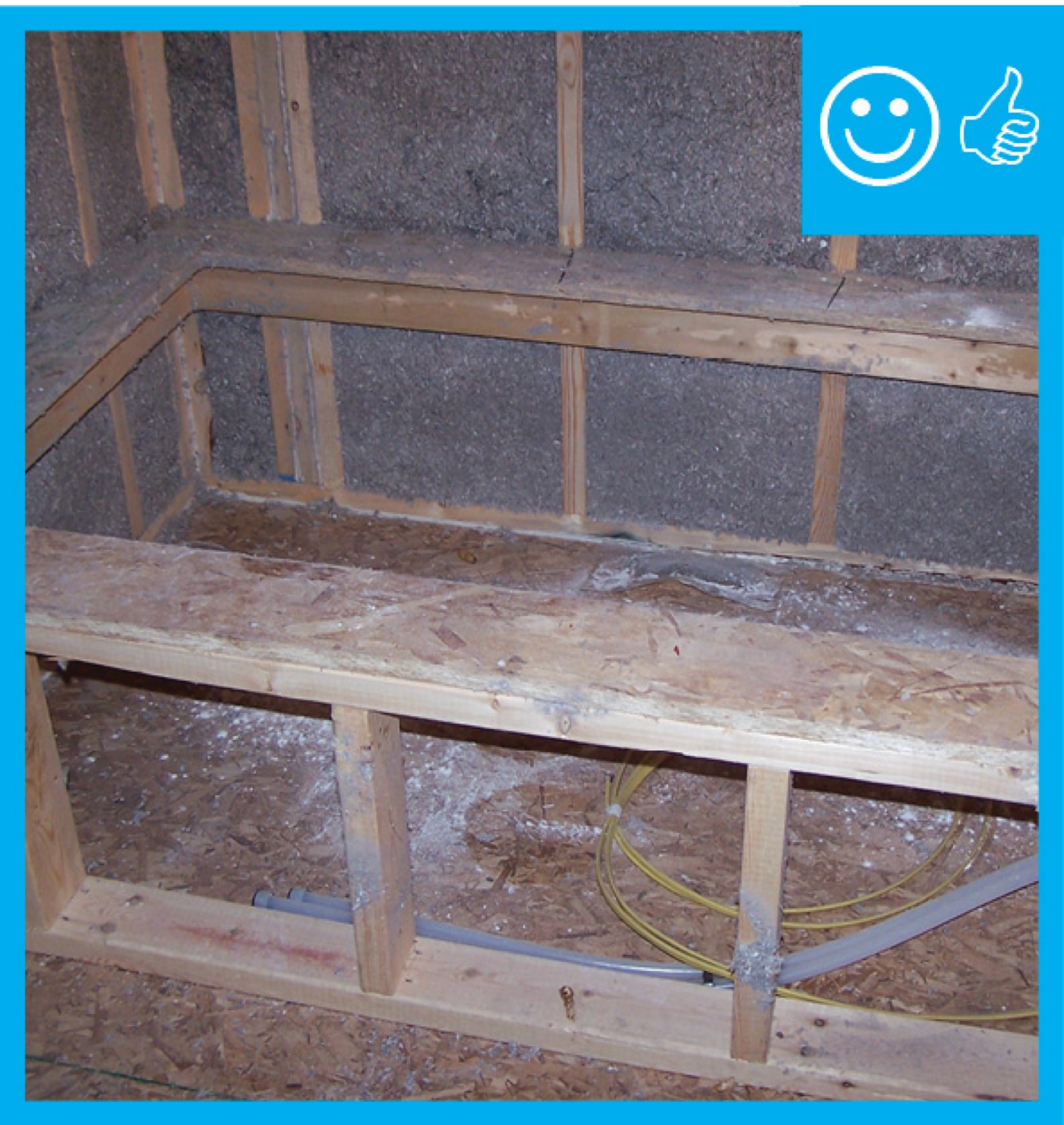
Right – Cantilever has been properly insulated, air sealed, and cavity has been blocked.
Image
Right – Closed-cell spray foam insulates and air-seals the rim joist above a shared wall between the garage and living space.
Image
Right – Closed-cell spray foam insulation in the shared wall between the garage and living space helps to air-seal the wall and protect occupants from garage pollutants.
Image
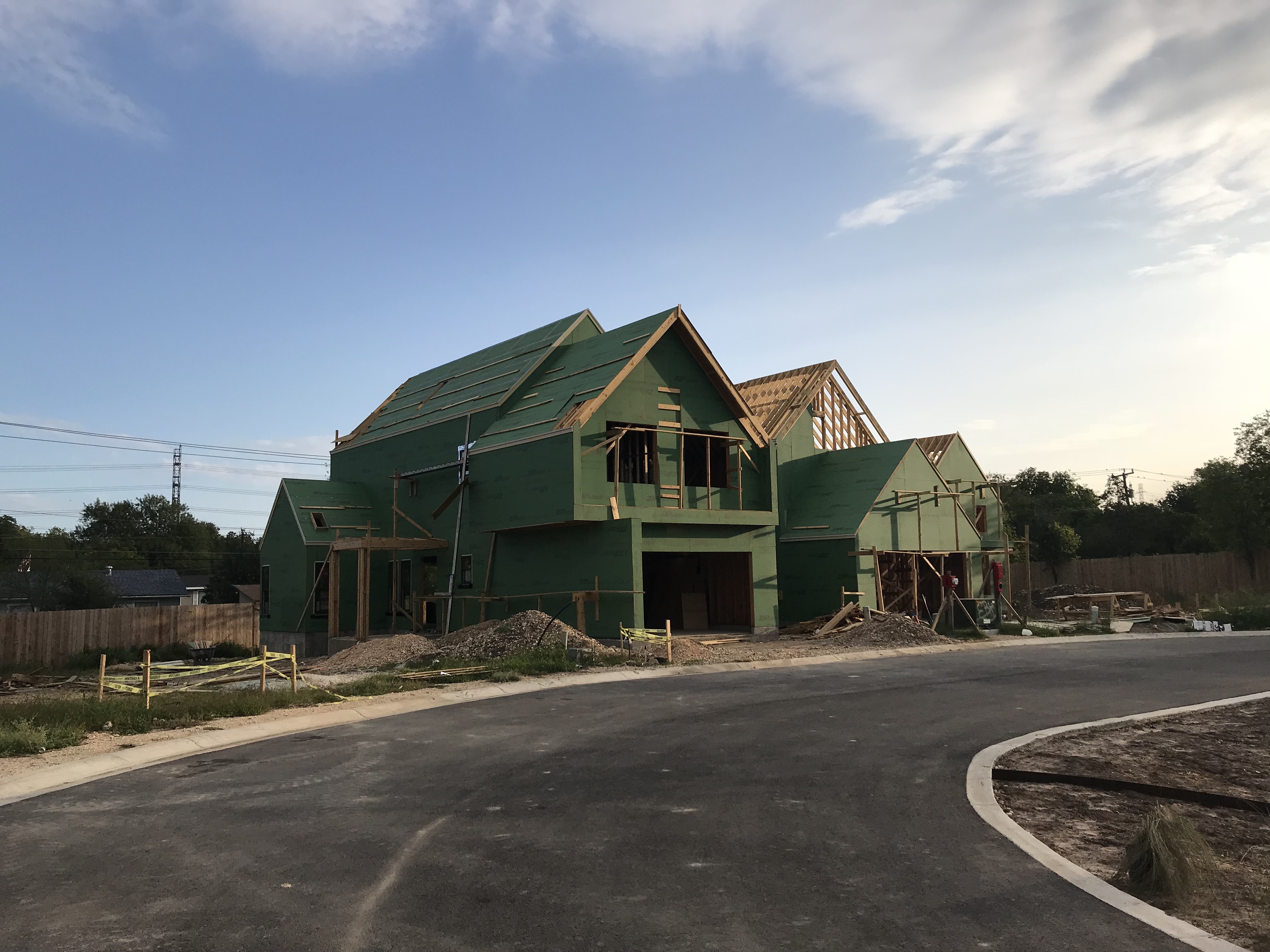
Right – Coated OSB provides a weather-resistant air barrier for this envelope of this home.
Image
Right – Coated OSB sheathing provides a continuous air and moisture barrier around the home.
Image
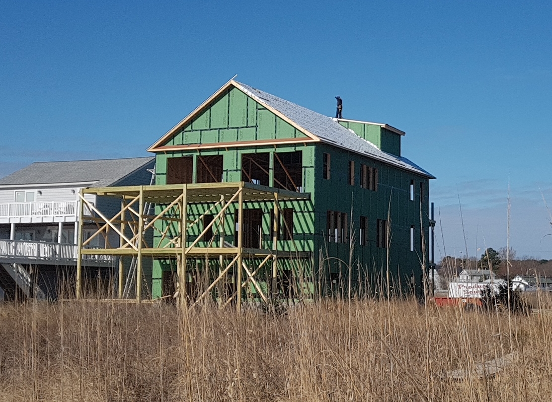
Right – Coated sheathing is taped at all seams to serve as an exterior air barrier on the walls.
Image
Image
Right – Every seam and nail hole in these garage-to-house walls is sealed with tape.
Image

Image

Image
Image
Image

Image
Image
Image
Image
Image
Image
Image
Image
Image
Image
Right – The building felt is installed on all exterior walls and provides a complete drainage system
Image
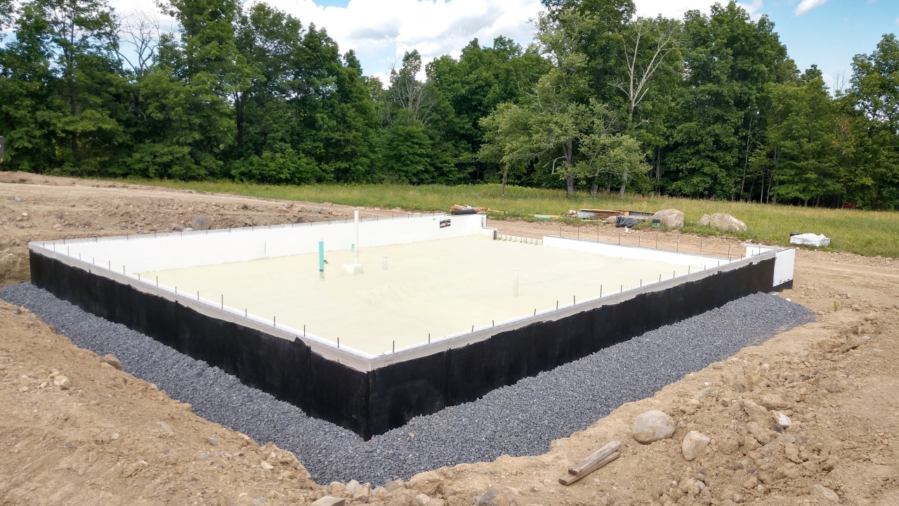
Right – The foundation of this ICF home was constructed of ICFs that were set in place on a gravel bed, then 3.5 inches (R-36) of closed-cell spray foam was sprayed directly onto the gravel, providing an effective air, vapor, and thermal barrier.
Image
Image
Right – The rigid insulation covers all exterior walls and all seams are taped to provide a complete drainage system
Image
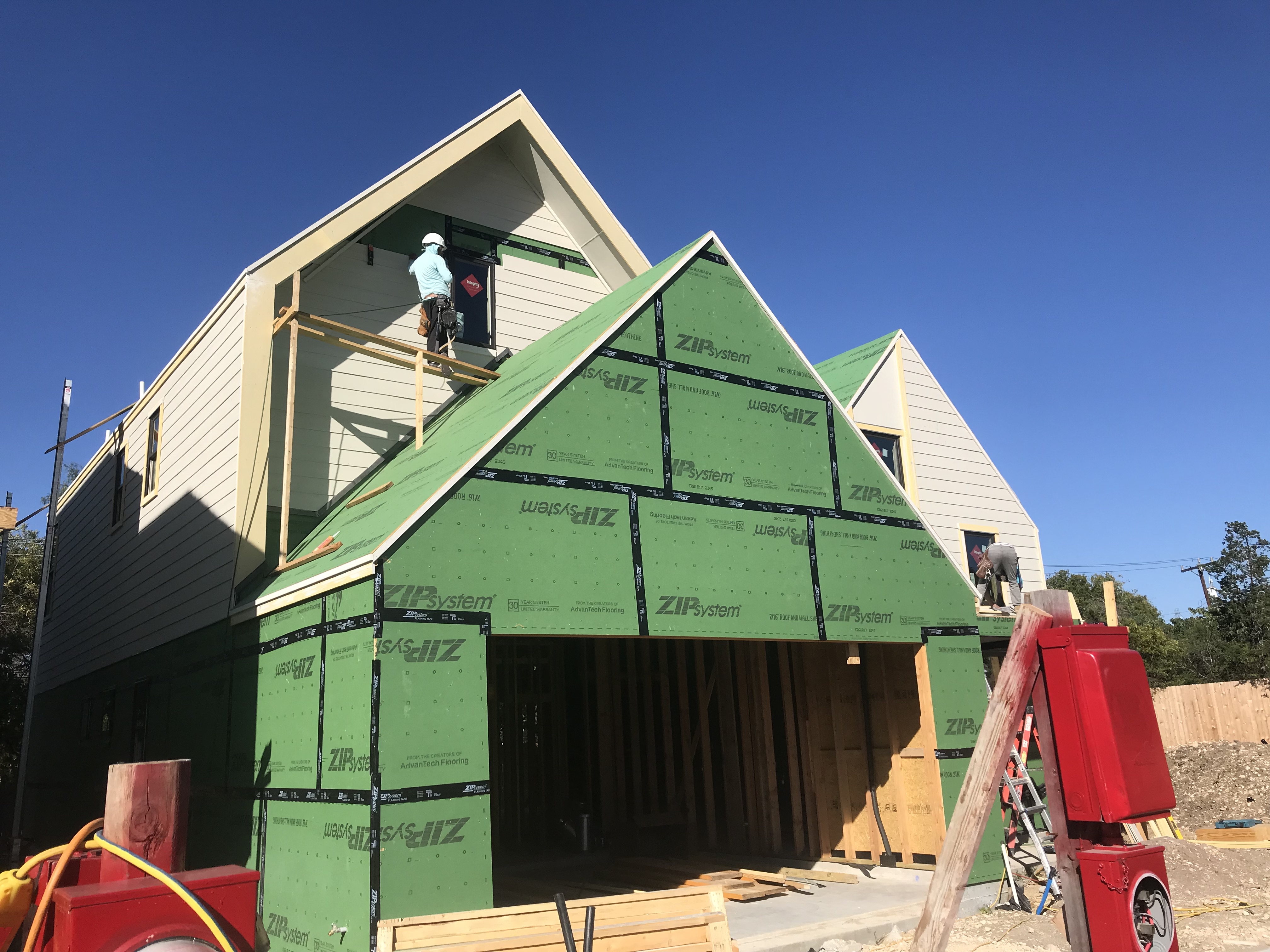
Right – The seams are taped on the coated OSB sheathing of this home to provide a complete air barrier.
Image
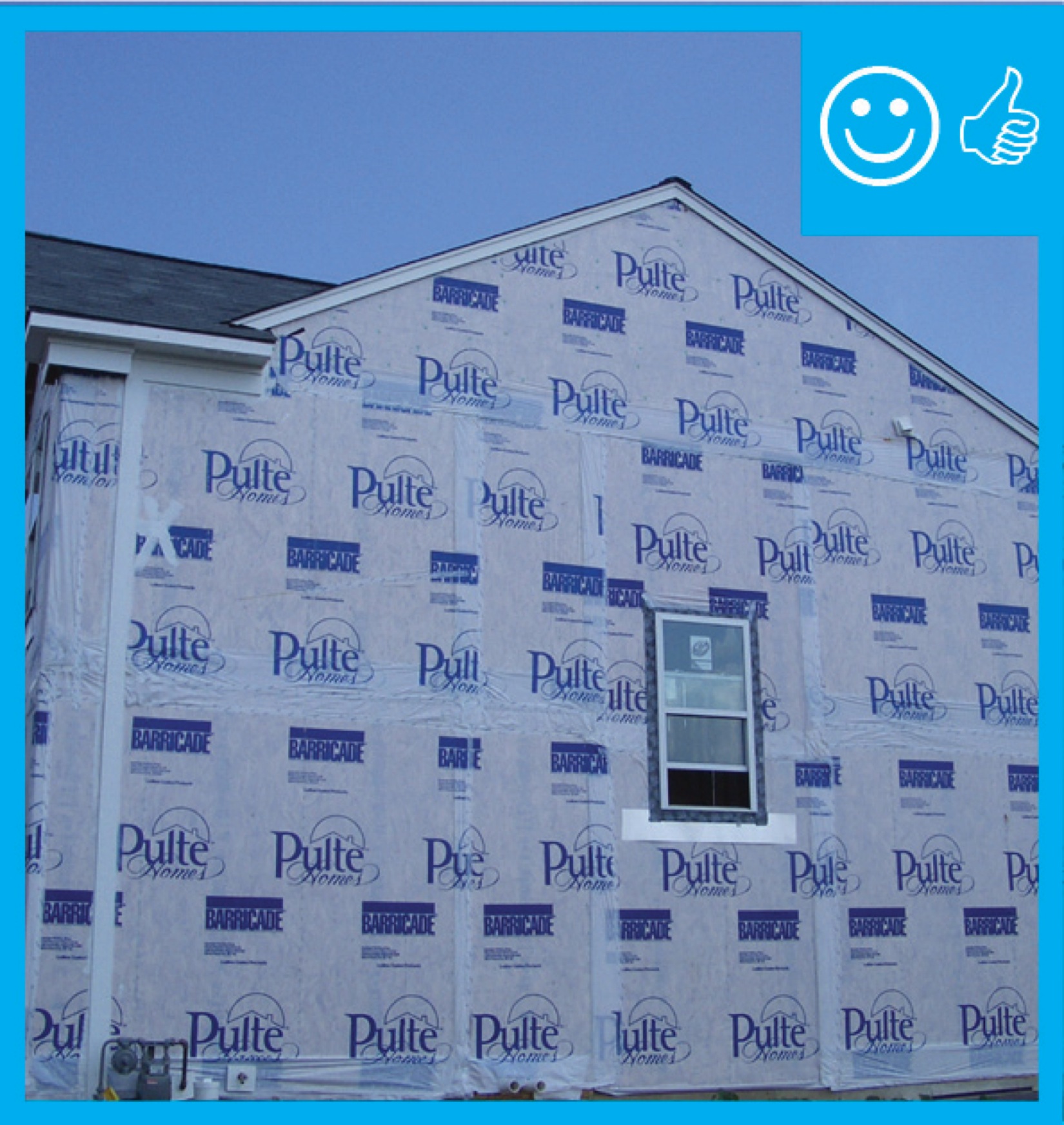
Right – The water-resistant barrier covers the entire house and the seams are taped to provide a complete drainage system
Image

Right – This attic knee wall and the floor joist cavity openings beneath it are being sealed and insulated with spray foam.
Image
Right – This foil-faced foam sheathing has taped seams and proper flashing details so it can serve as a drainage plane.
Image
Image
Image
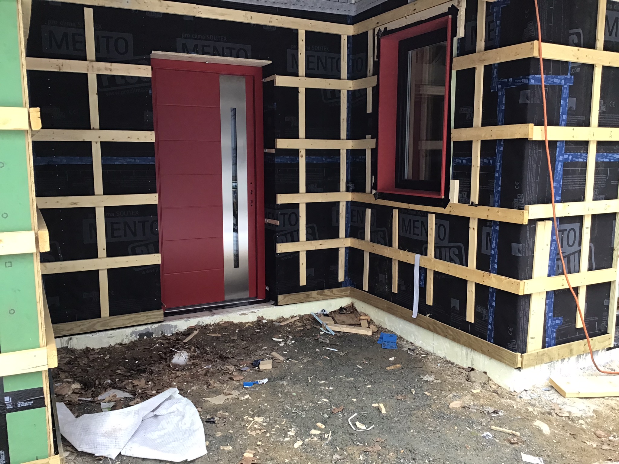
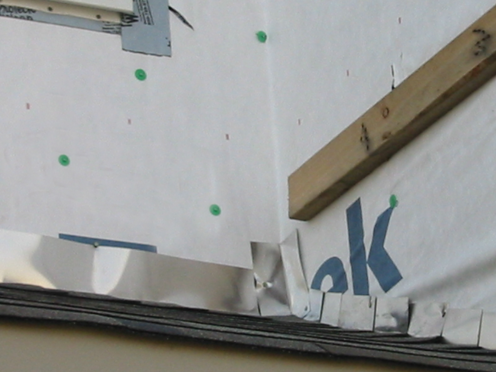
Right – Vertical and horizontal furring strips are installed over a breathable membrane weather resistant barrier to create an air gap and drainage plane behind the wood siding that will be installed next.
Image
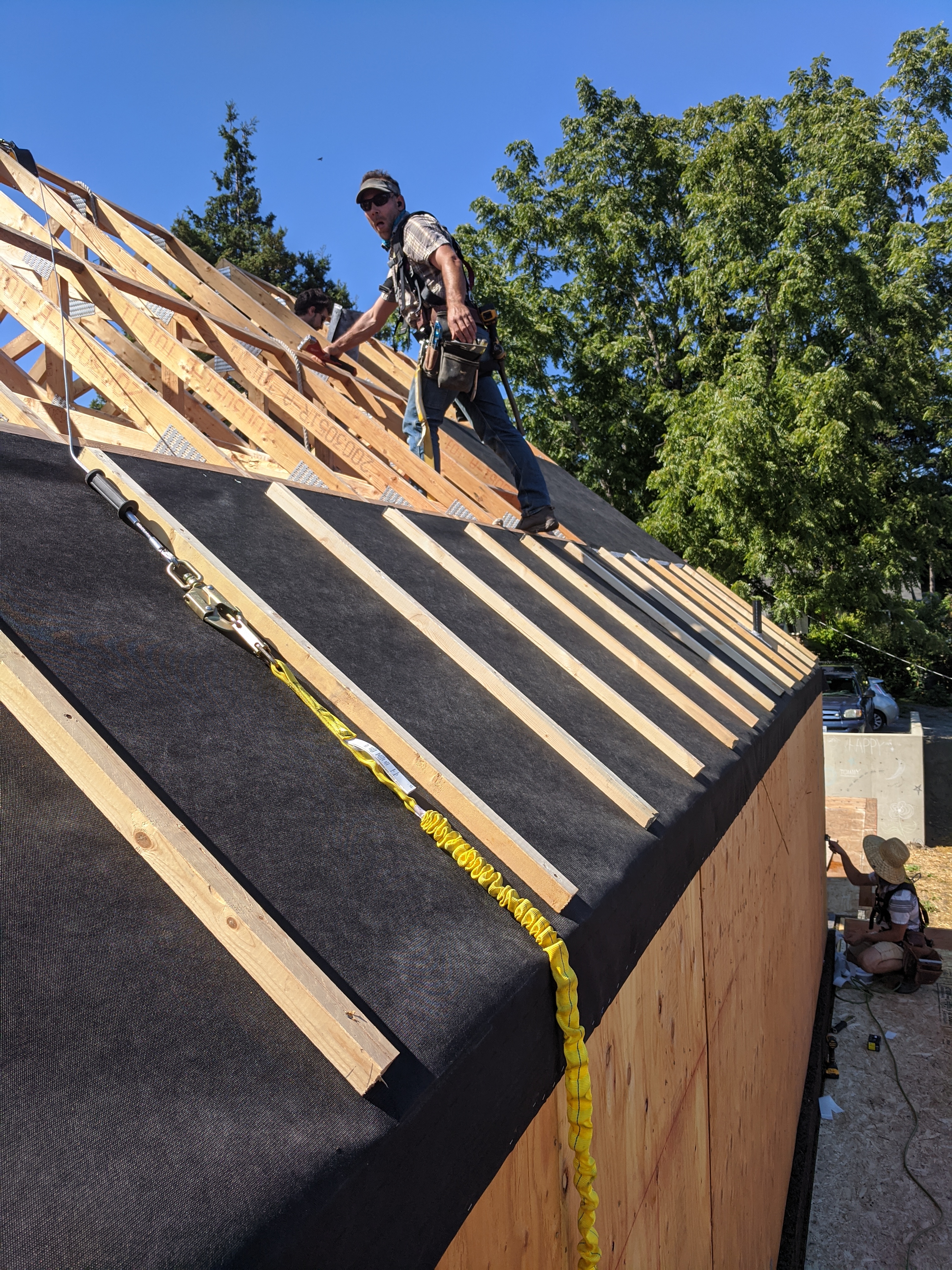
Right – Wind baffle installation maintains necessary code clearance between baffle and roof deck
Image
Image
Right – Wood-to-sheathing joints are caulked so the sheathing can provide an air barrier for the home.
Image
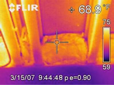
Right-- IR photo shows how effectively spray foam insulated/air sealed attic kneewall and the floor cavities under kneewall
Image

Image
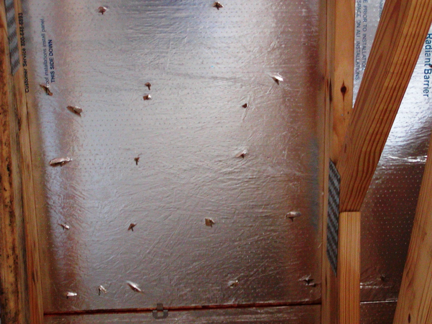
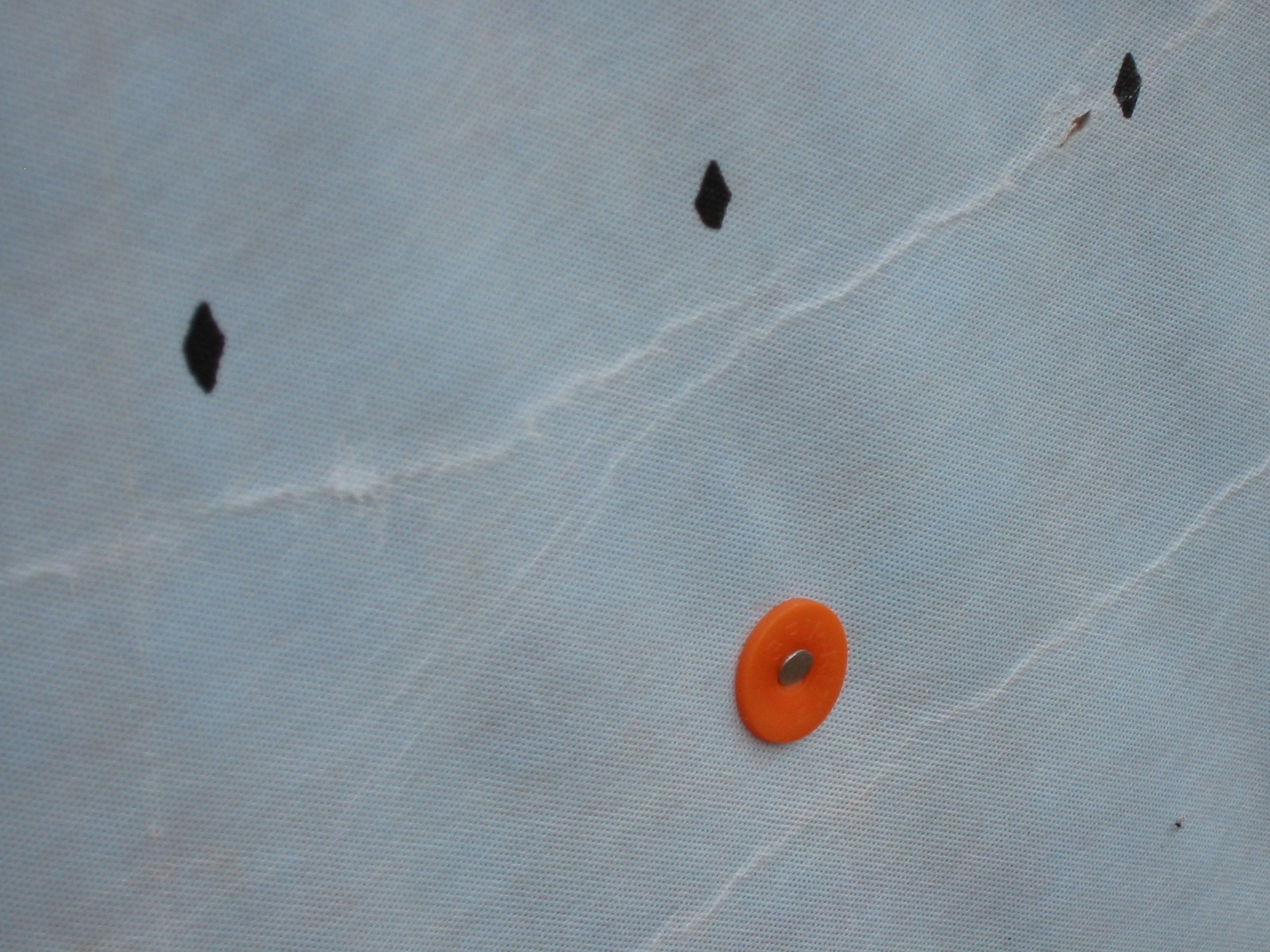
Roof decking has adhered radiant barrier that is perforated, in addition to the nail holes
Image
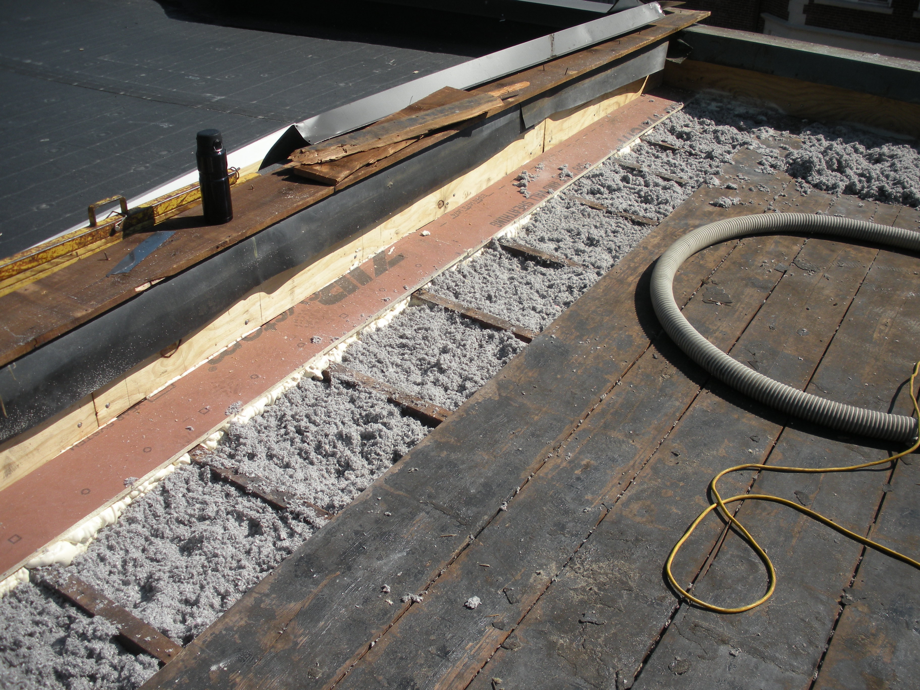
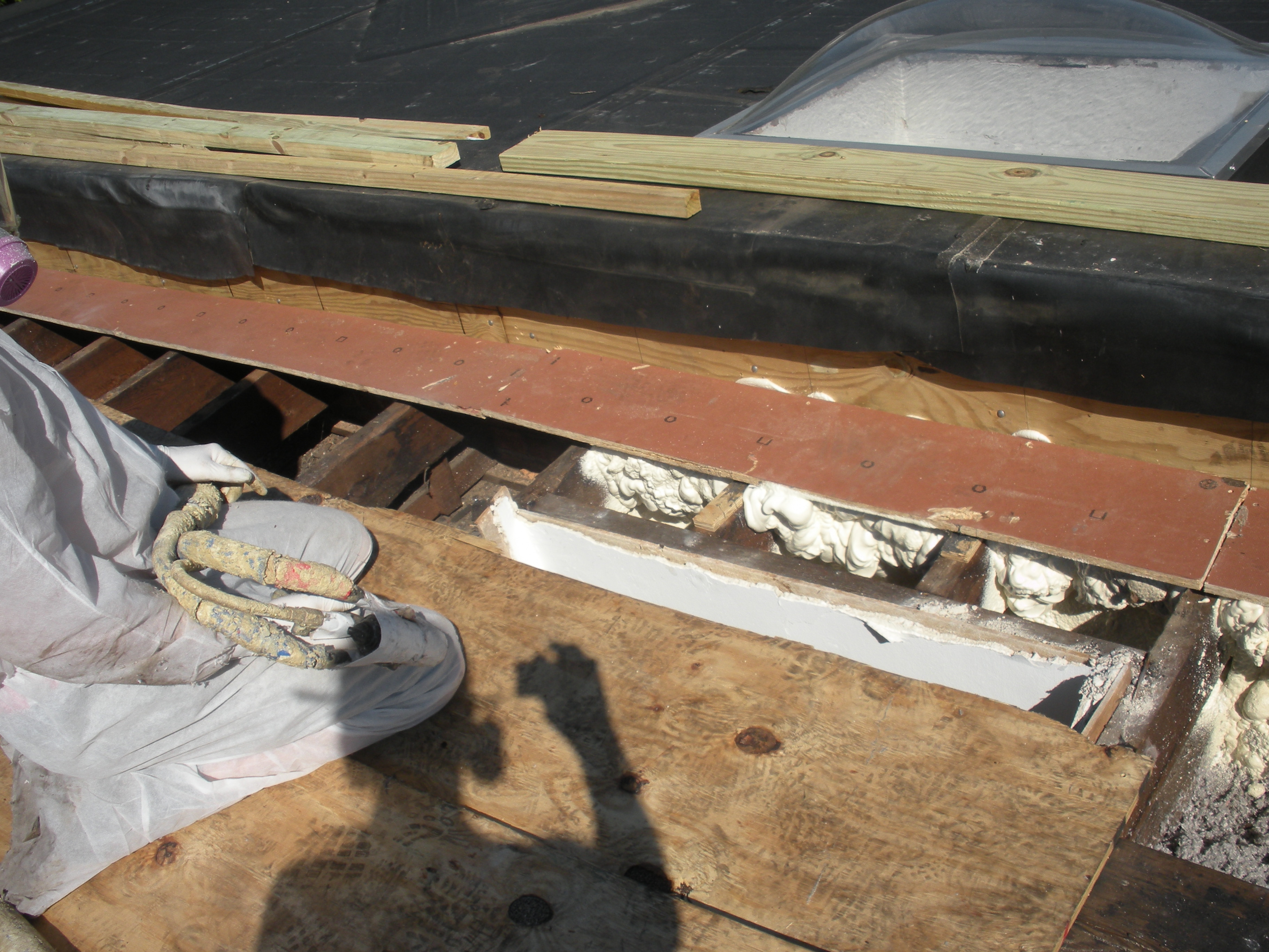
Roofing paper protects the top of the new plywood parapet while the base of the parapet is air sealed with spray foam and fibrous insulation is installed in the rafter cavities in this flat roof retrofit
Image
Stucco is installed over rigid insulation, which is installed over a drainage plane consisting of a drainage gap and building wrap layer over the sheathing
Image
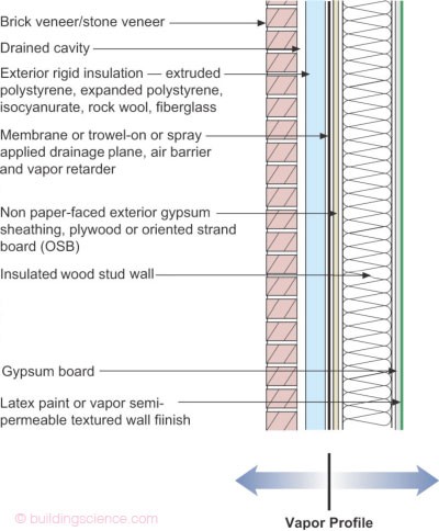
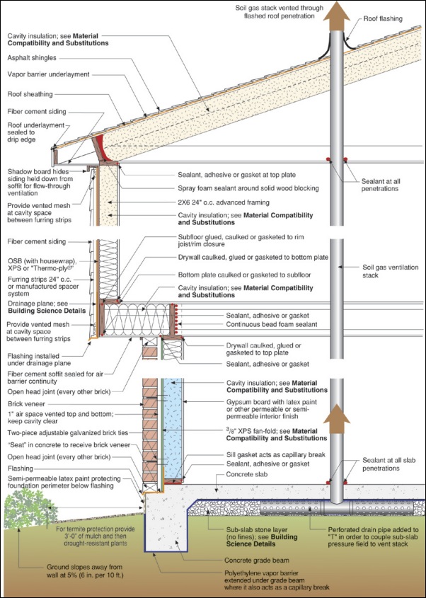
The “institutional” perfect wall works in all climate zones; water, air, vapor, and thermal control layers are exterior of the sheathing, assembly allows drying to interior and exterior
Image
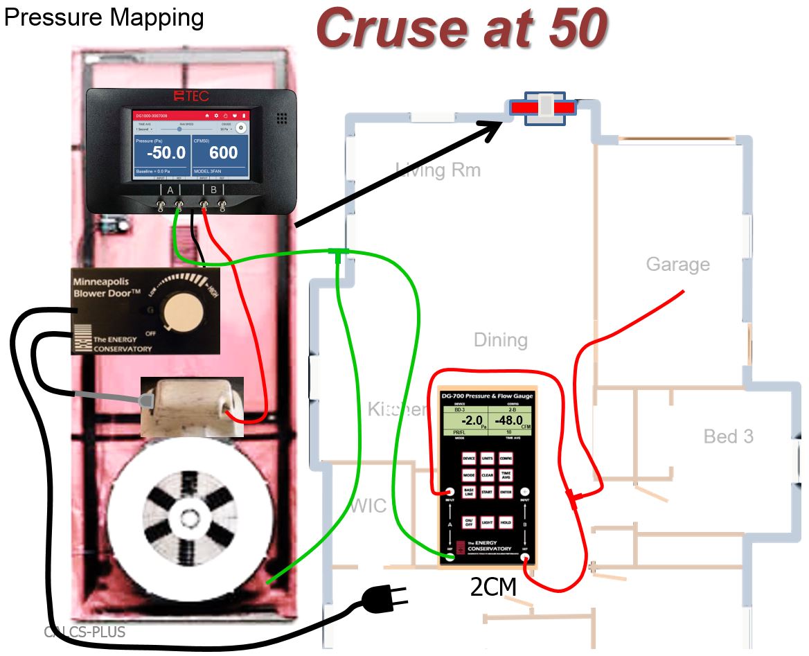
The air tightness of the garage-to-house air barrier can be tested with a blower door kit and two manometers
Image
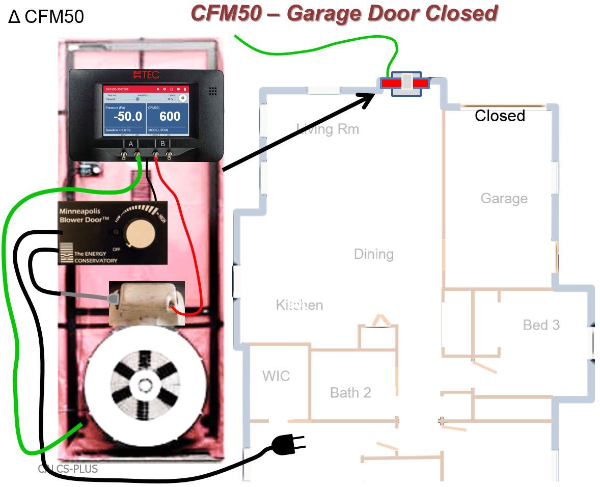
The air tightness of the house-garage air barrier can be tested using a CFM50 test that is first run with the garage door to outdoors closed
Image
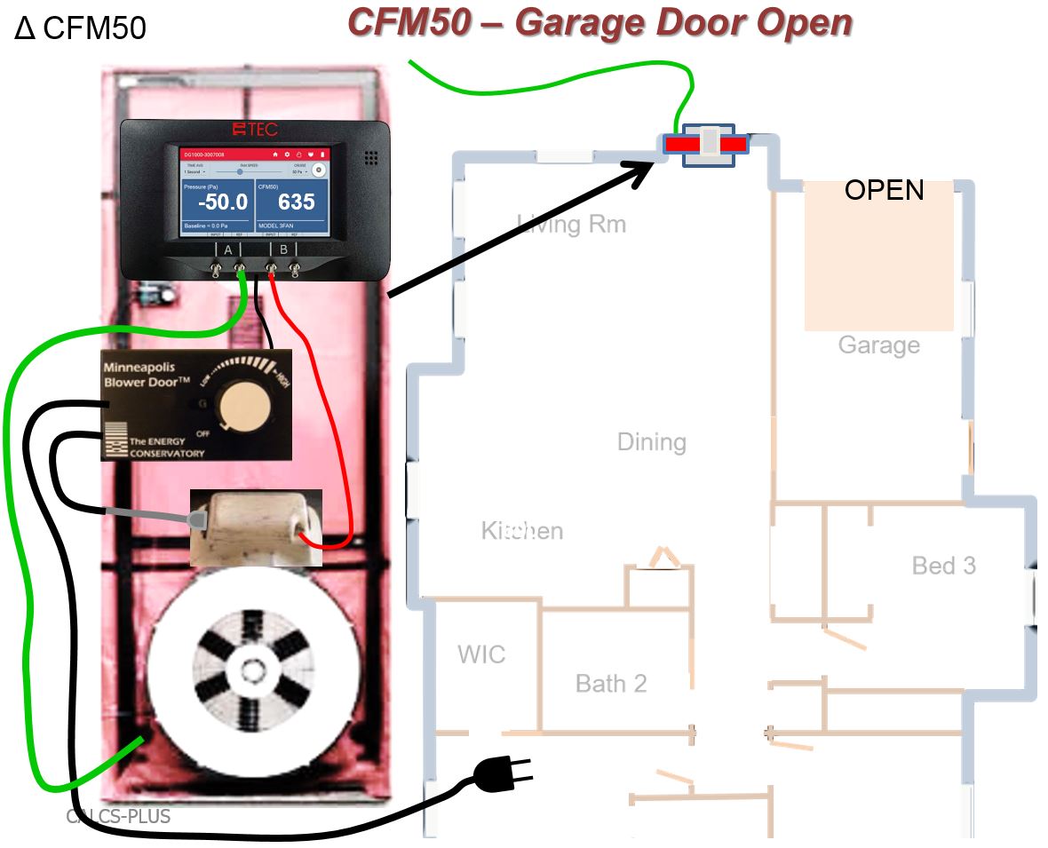
The air tightness of the house-garage air barrier can be tested using a CFM50 test that is run first with the garage door to outdoors closed and then with the overhead garage door to outdoors open
Image
The attic knee walls were constructed from 2x6s and insulated with R-19 batt, backed with 1 inch of XPS foam board with taped joints to provide a solid air barrier over the insulated surfaces.
Image
The attic kneewall and the open floor cavities under kneewall are both sealed and insulated in one step with spray foam insulation
Image
The base of the plywood parapet is air sealed with spray foam and fibrous insulation is installed in the rafter cavities in this flat roof retrofit
Image
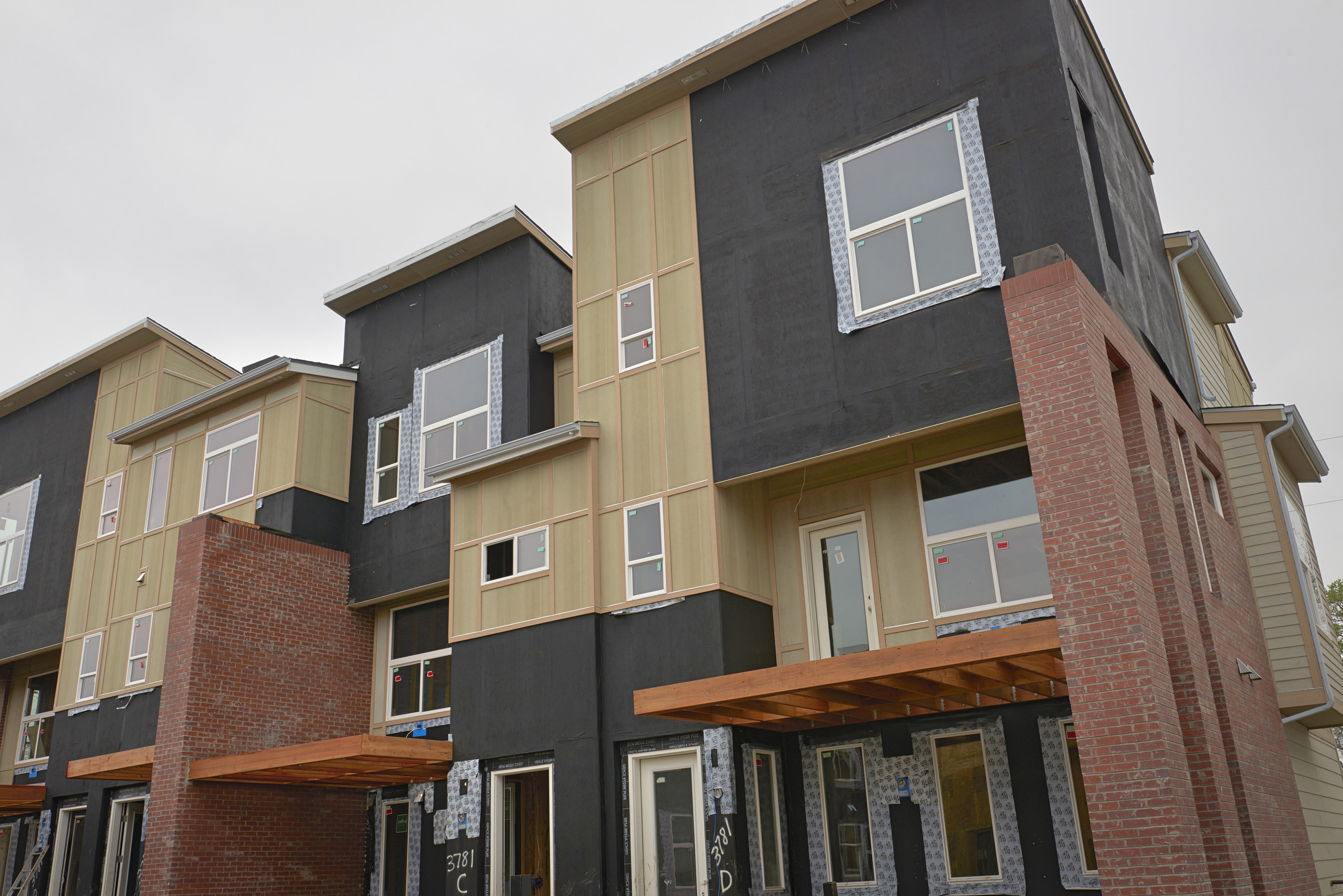
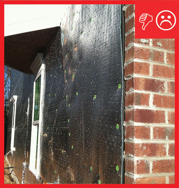
The black coating on these walls is a liquid-applied asphalt-based air and moisture barrier.
Image
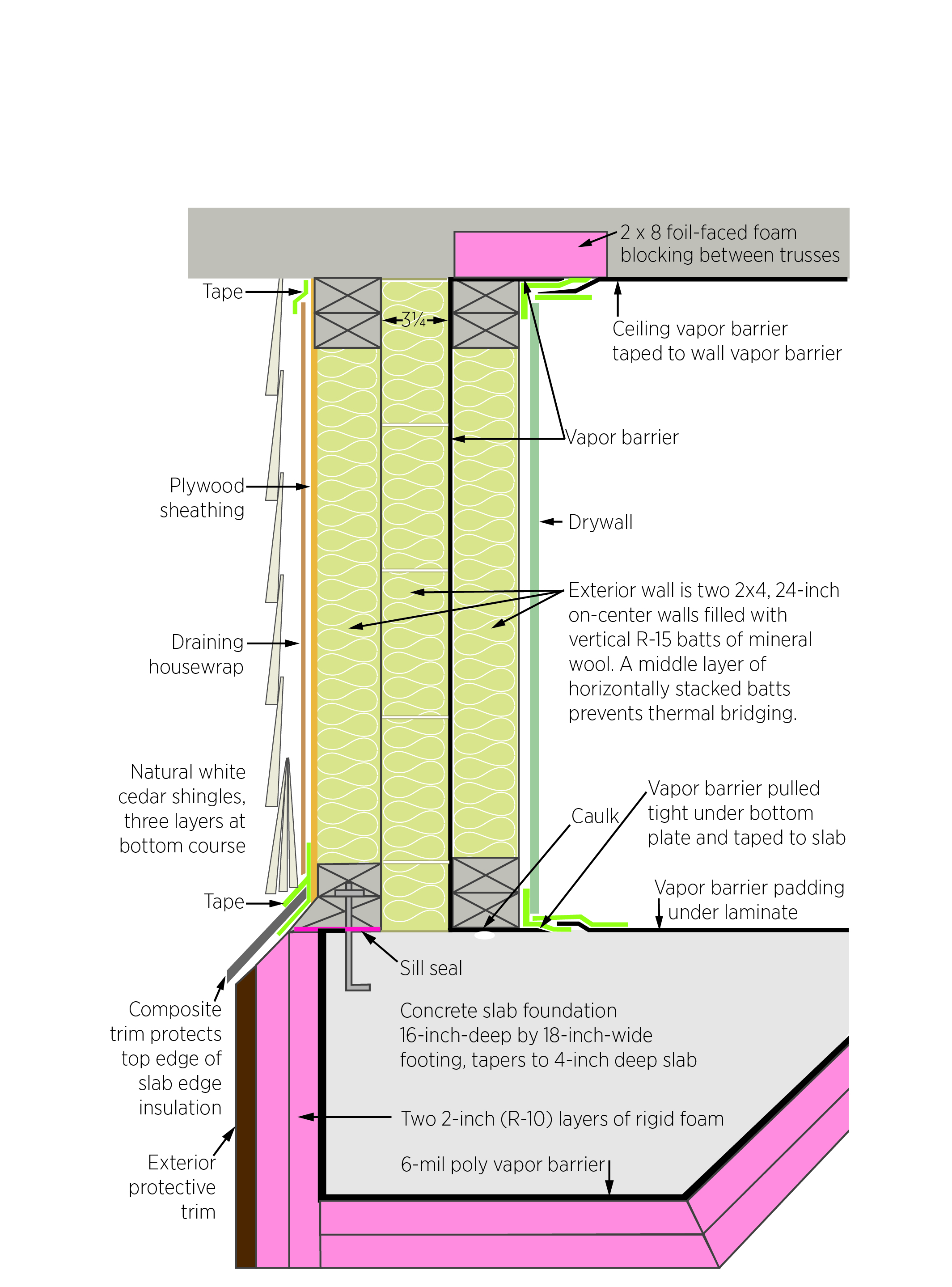
The builder in this very cold climate installed three layers of unfaced mineral wool batt in the double wall with a code-required vapor barrier between the middle and inner layers of wall insulation that is taped to barriers in the ceiling and floor.
Image
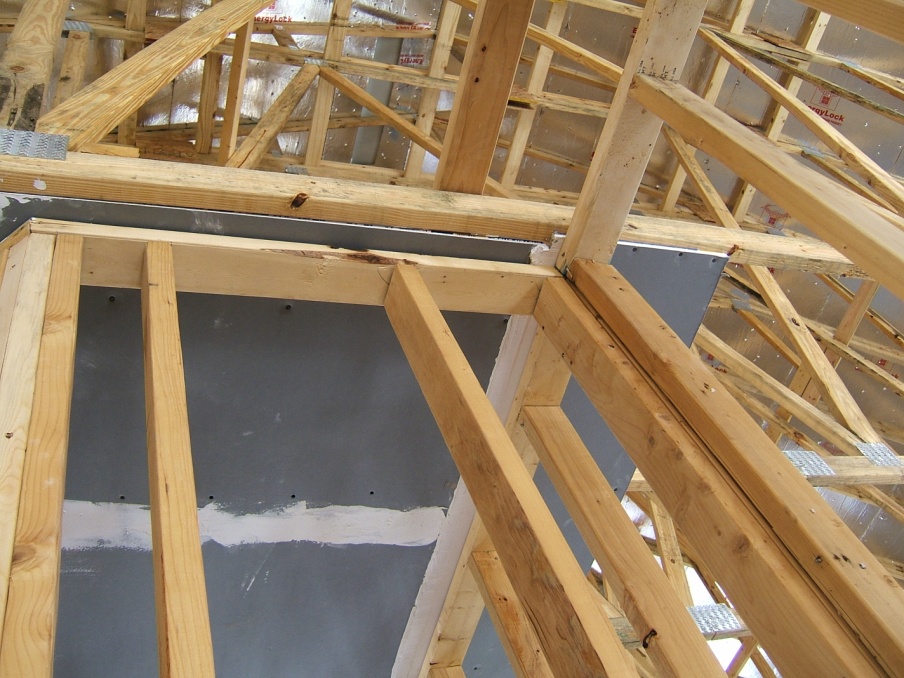
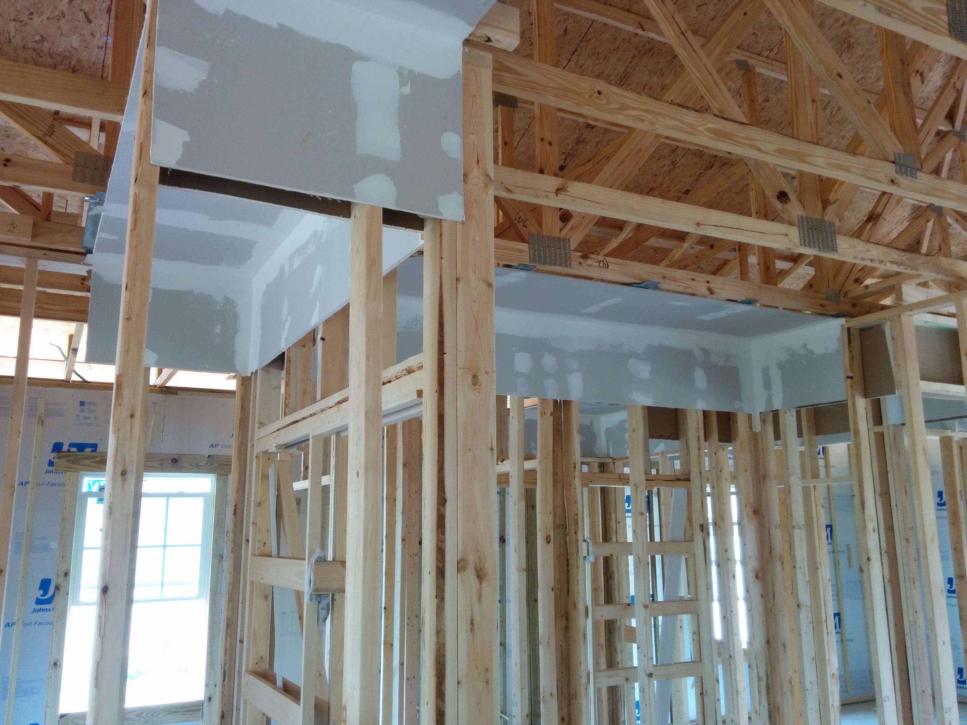
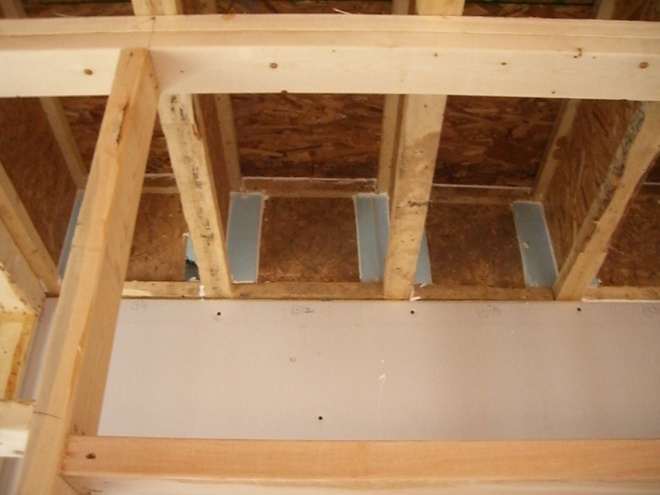
The drywall above the chase extends beyond adjoining top plates for a continuous air barrier
Image
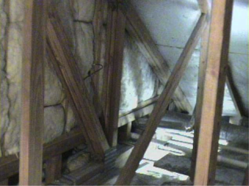
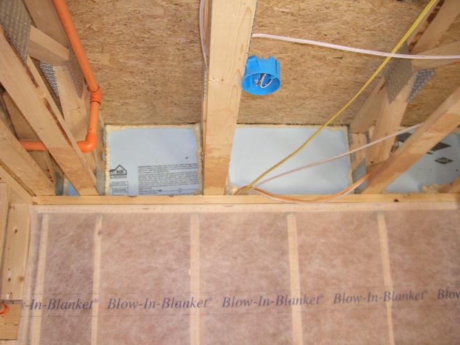
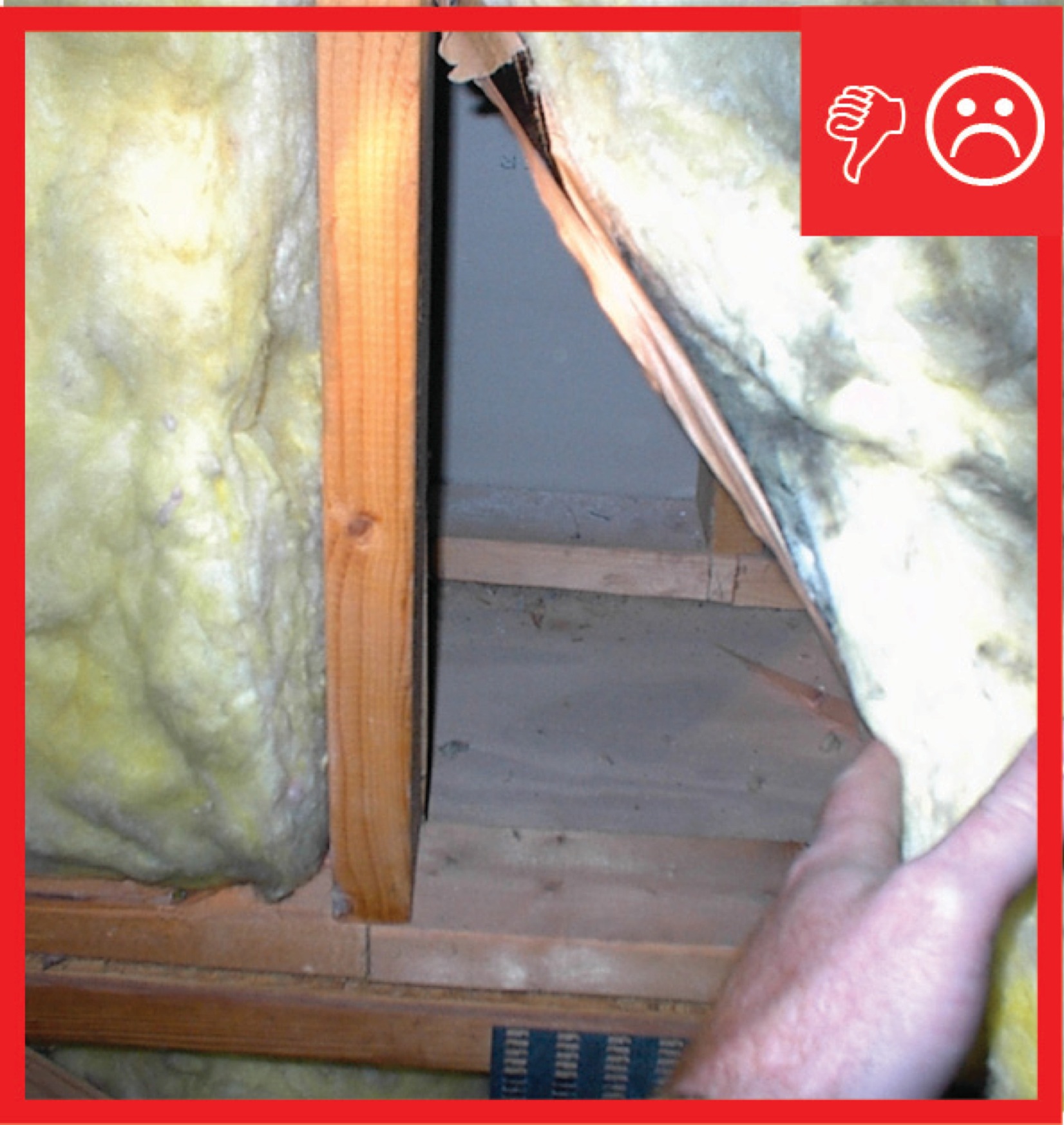
The floor cavities under this attic kneewall are completely open to the unconditioned attic space and a prime target for wind washing
Image

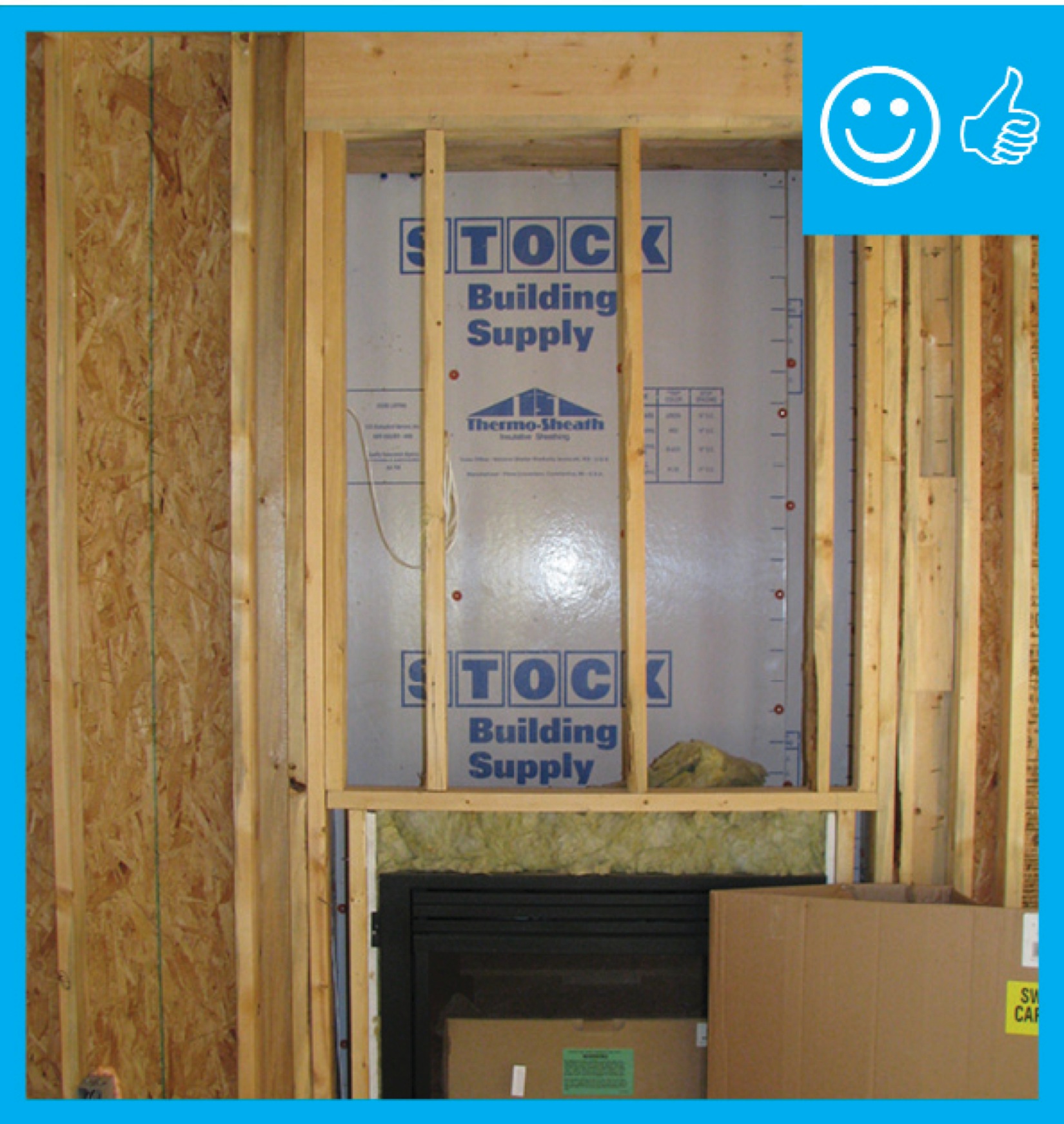
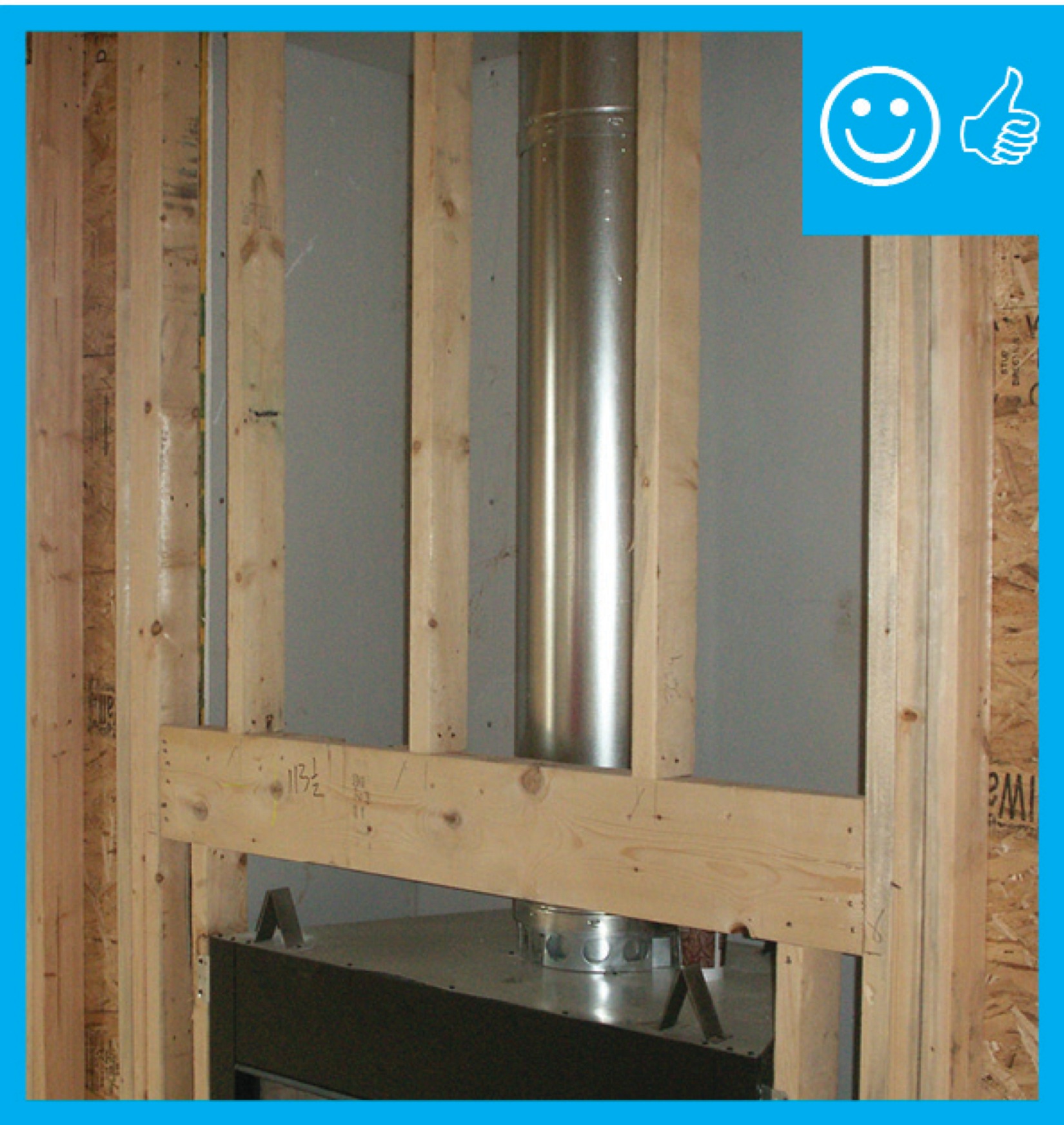
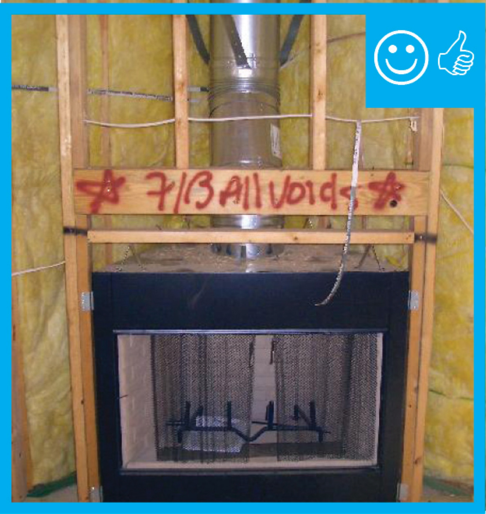
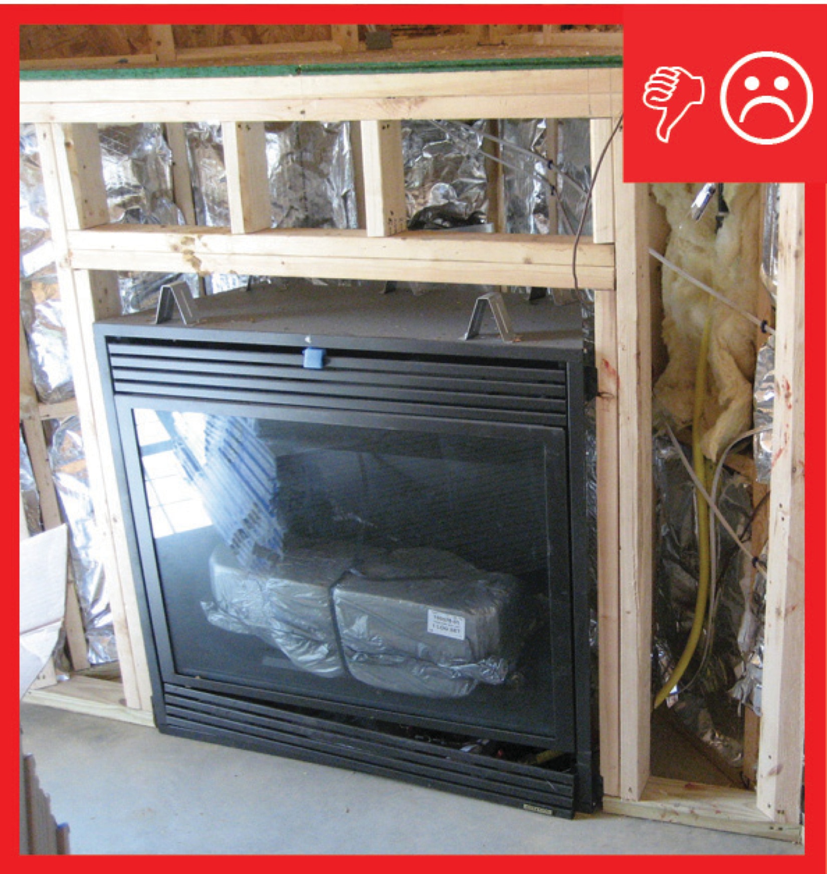
The foil-faced insulation behind this fireplace provides an air barrier and thermal shield.
Image
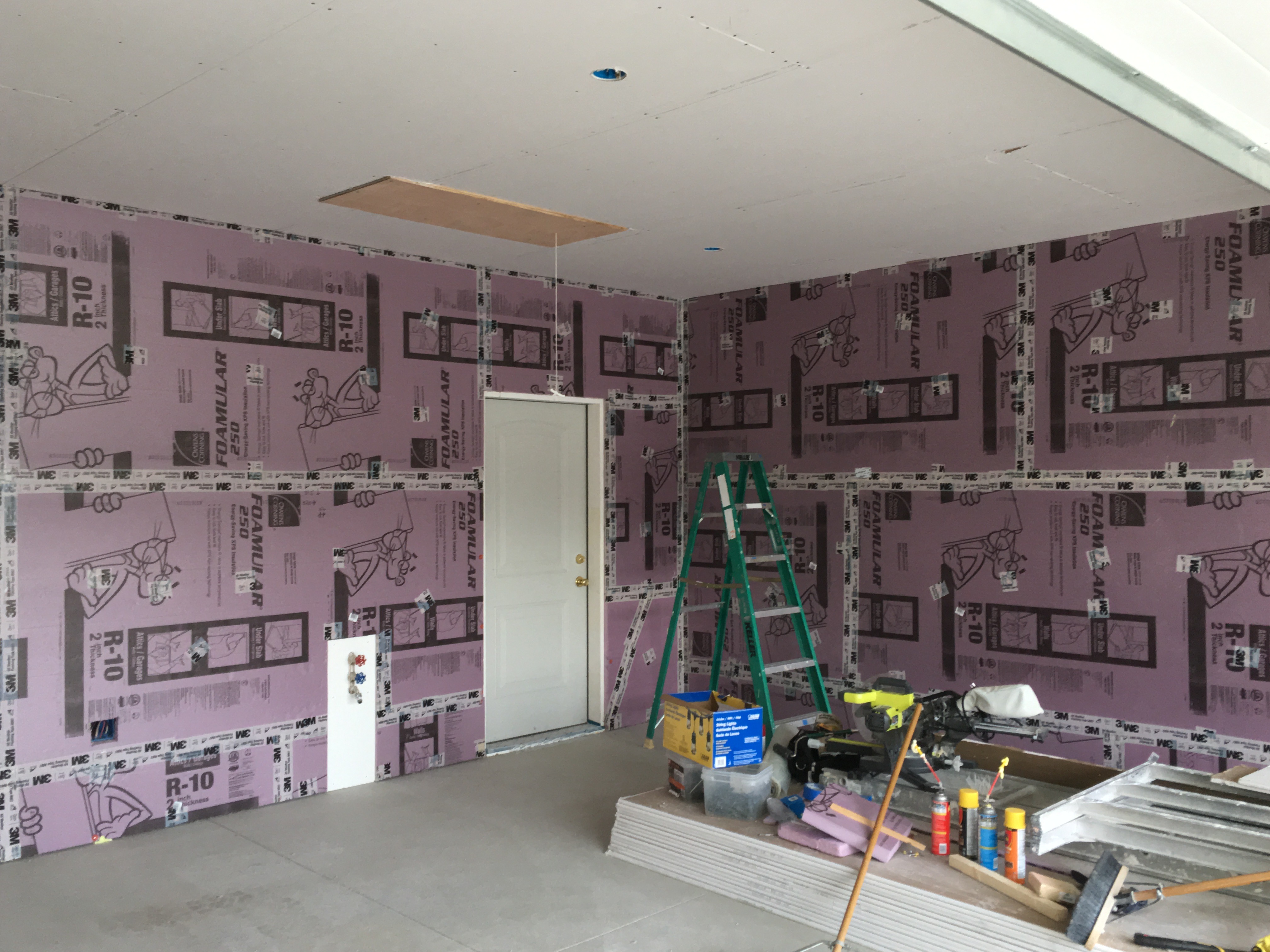
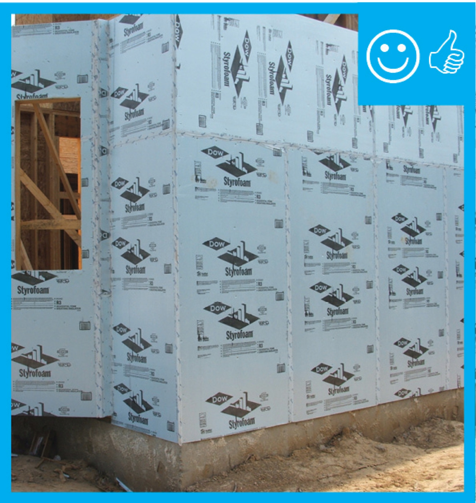
The home is sheathed with rigid foam insulation and all seams and holes are taped to provide a continuous air barrier.
Image
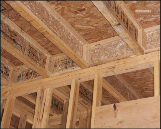
The I-joist is continuous along the shared wall and serves as a natural air barrier between the garage and the house
Image
Image
Image
Image
The Perfect Wall includes water, air, thermal, and vapor layers with continuous insulation exterior of the sheathing to reduce the condensation potential in the wall.
Image
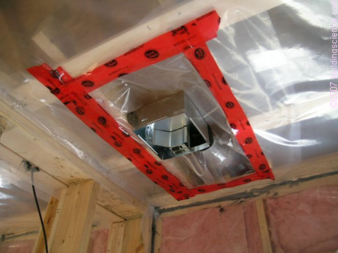
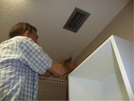
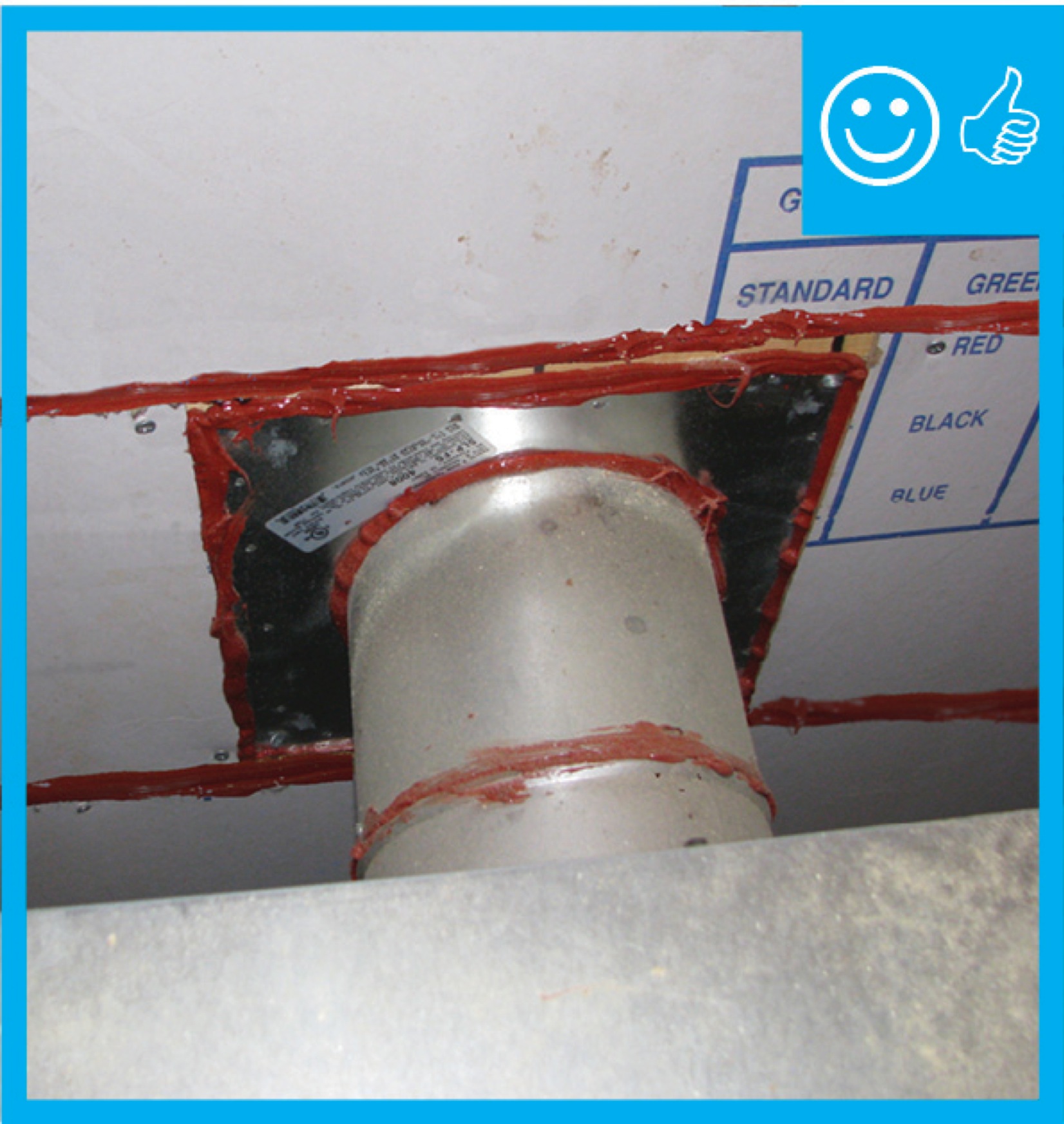
The polyethylene ceiling vapor barrier is sealed to form an air barrier around the exhaust fan in this very cold climate location (≥ CZ 6).
Image
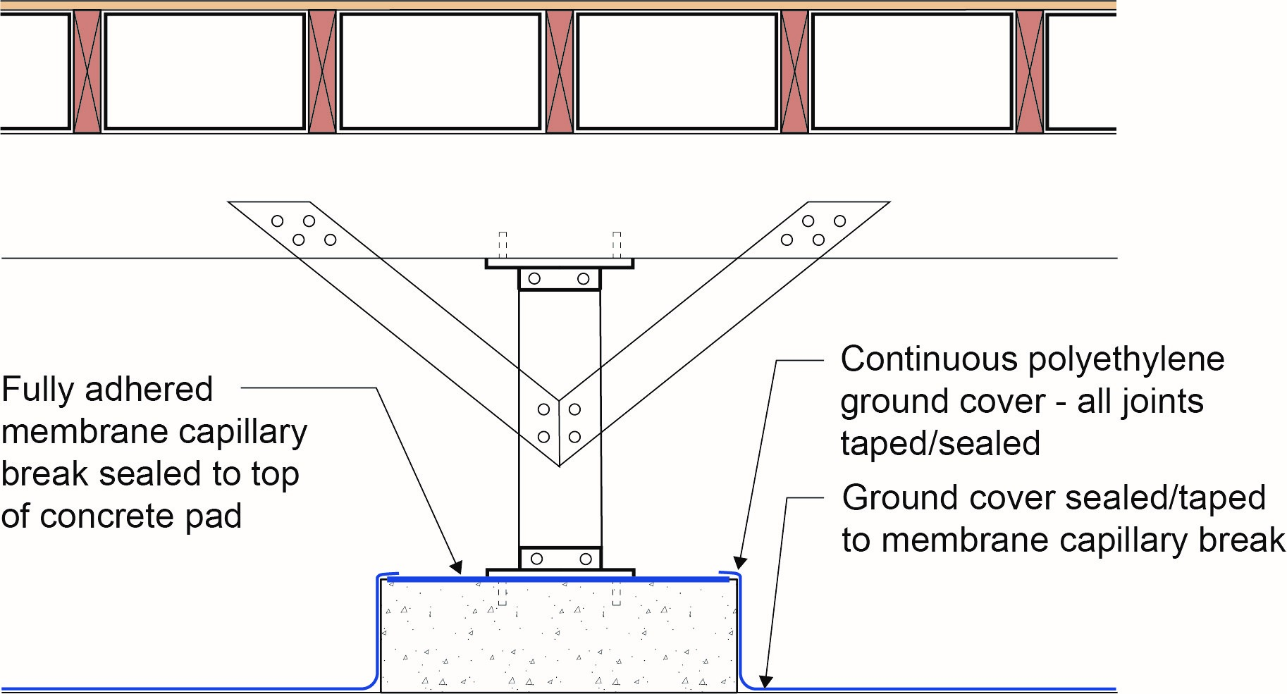
The polyethylene ground cover in the crawl space is lapped up sides of piers to posts to provide a continuous air and vapor barrier
Image
The soffit dam and baffle allow air to flow through the vents without disturbing the insulation covering the top plates
Image
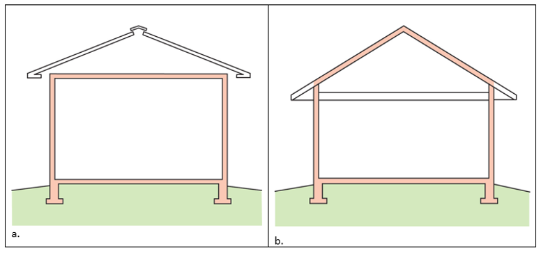
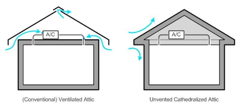
The thermal boundary for a gable roof can be located at either a) the flat ceiling with a vented attic or b) the roof line for an unvented attic
Image
The wall behind the fireplace is an exterior wall and requires a thermal barrier that is continuous with the rest of the wall’s insulation
Image
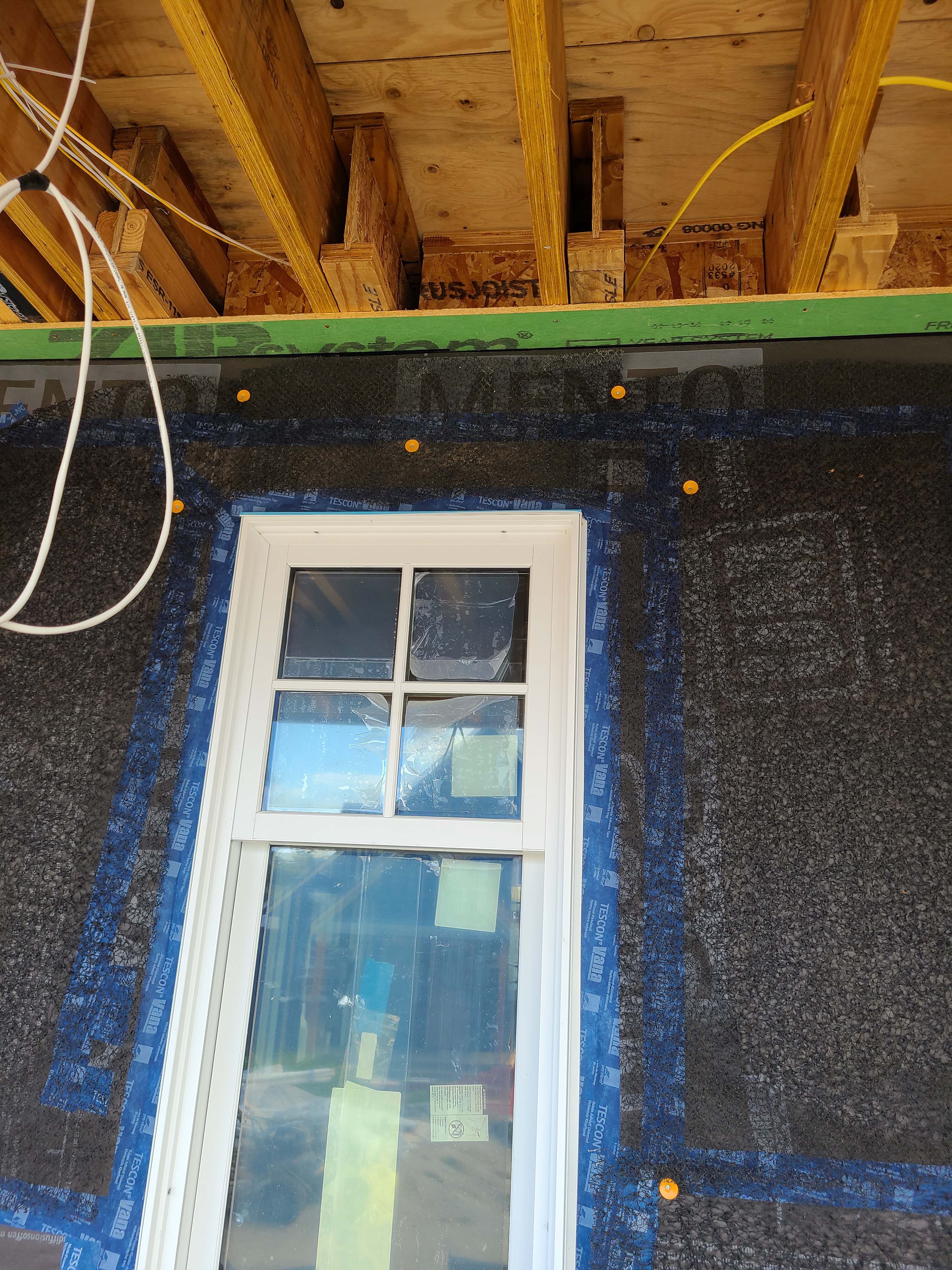
The windows in this building are connected to the fully adhered water and air control layer using fluid-applied flashing
Image
There are three potential locations for an attic radiant barrier – adhered to the underside of the roof decking, hanging from the rafters, or on the ceiling insulation
Image
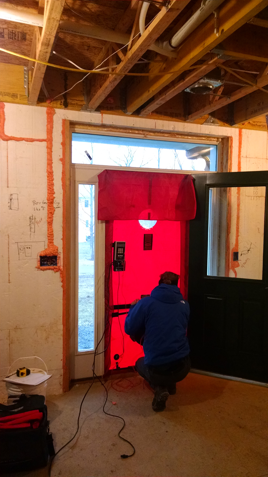
These ICF homes are blower door tested during construction, before the drywall is installed, when air leaks can be easily sealed.
Image
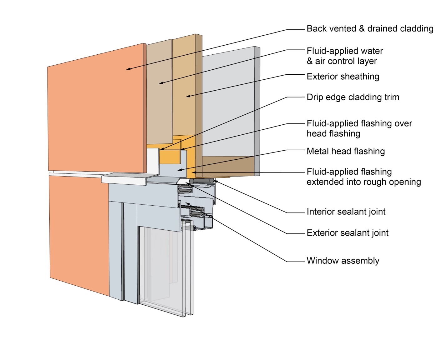
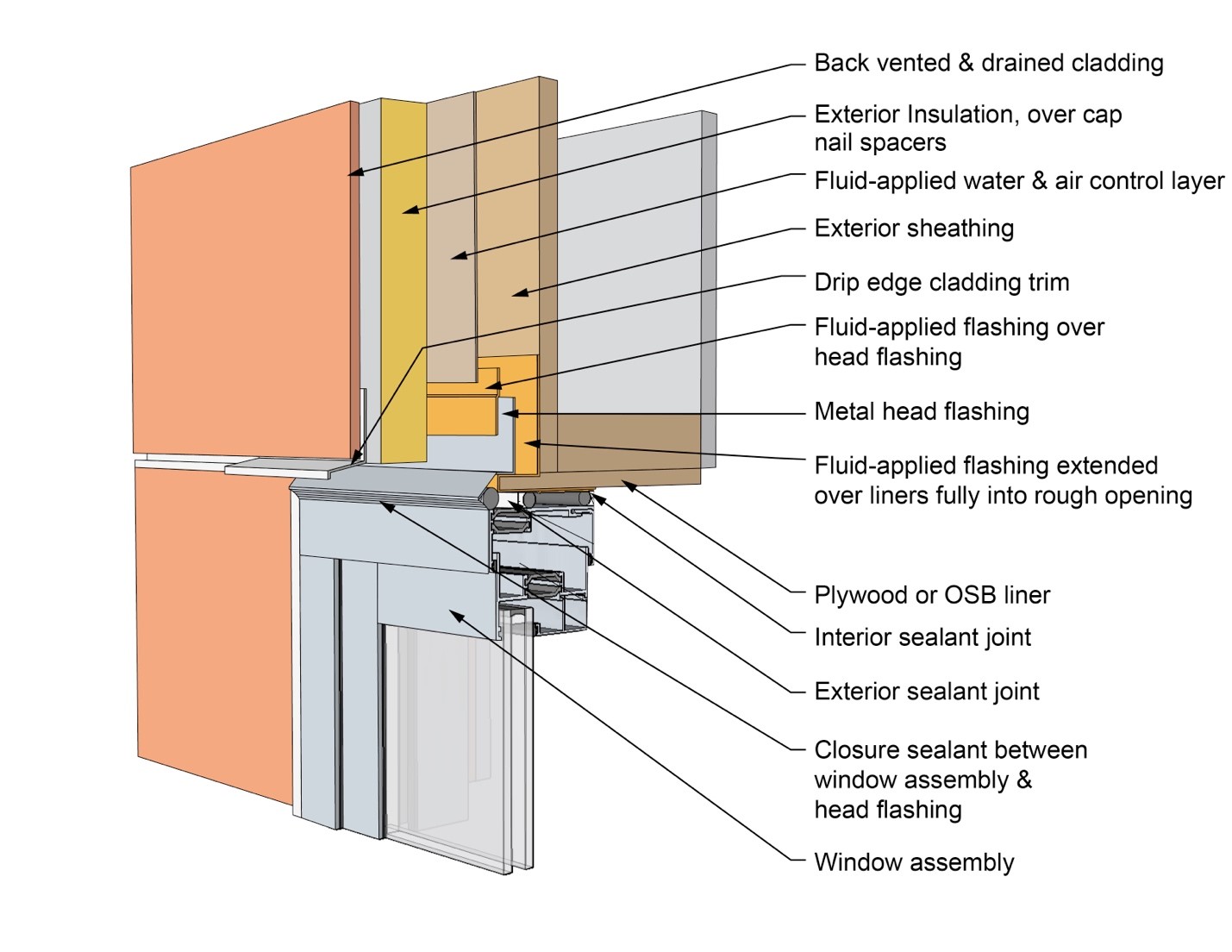
This drawing shows key head details for a window installation using a fluid-applied flashing on a wall with a fluid-applied water and air control layer
Image
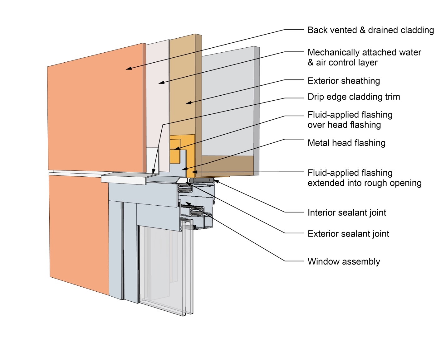
This drawing shows key head details for a window installation using a fluid-applied flashing on a wall with a mechanically attached water and air control layer
Image
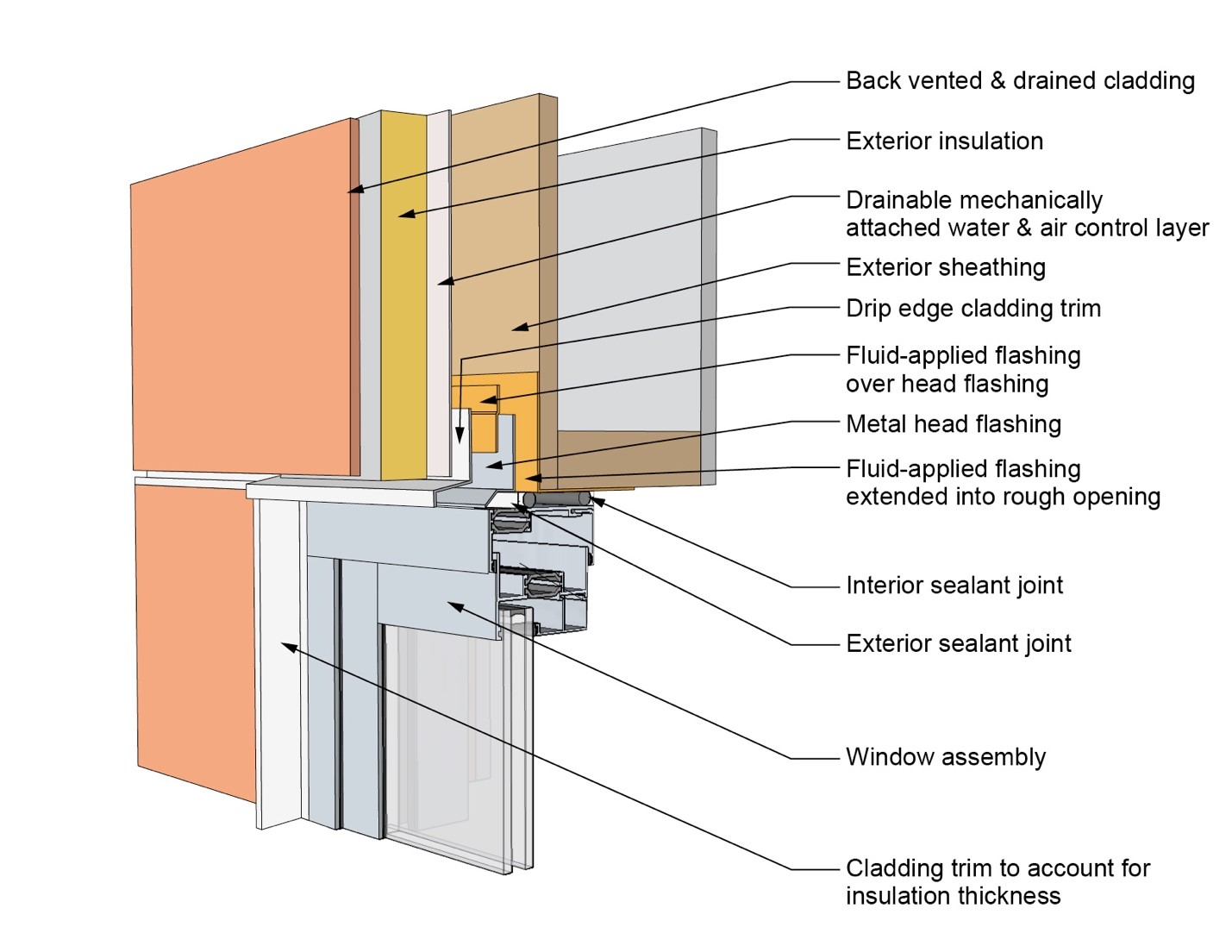
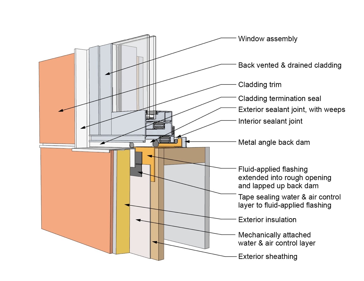
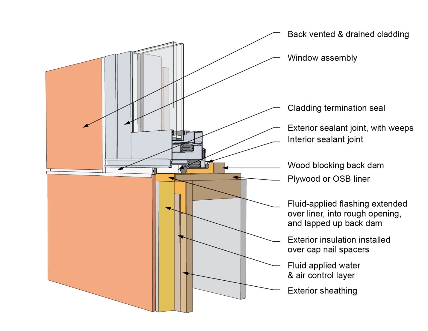
This drawing shows key head details for a window installation using a fluid-applied flashing on a wall with a mechanically attached water and air control layer and continuous insulation
Image
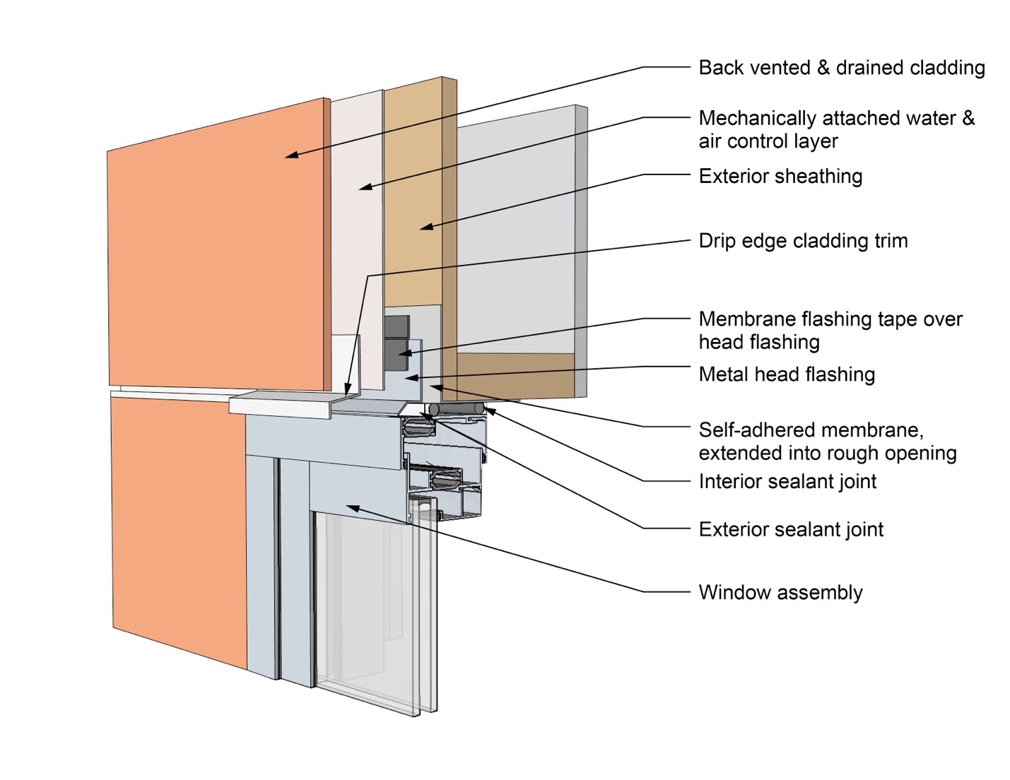
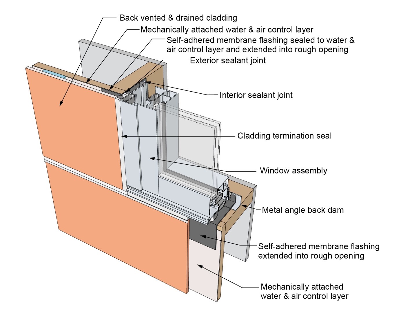
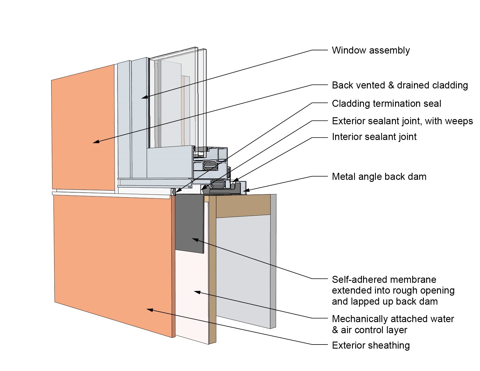
This drawing shows key head details for a window installation using a self-adhered membrane tape flashing on a wall with a mechanically attached water and air control layer
Image
This drawing shows key head details for an “outie” window installation using a fluid-applied flashing on a wall with a fluid-applied water and air control layer and continuous insulation
Image
This drawing shows key jamb details for a window installation using a fluid-applied flashing on a wall with a fluid-applied water and air control layer
Image
This drawing shows key jamb details for a window installation using a fluid-applied flashing on a wall with a mechanically attached water and air control layer
Image
This drawing shows key jamb details for a window installation using a fluid-applied flashing on a wall with a mechanically attached water and air control layer and continuous insulation
Image
This drawing shows key jamb details for a window installation using a self-adhered membrane tape flashing on a wall with a mechanically attached water and air control layer
Image
This drawing shows key jamb details for an “outie” window installation using a fluid-applied flashing on a wall with a fluid-applied water and air control layer and continuous insulation
Image
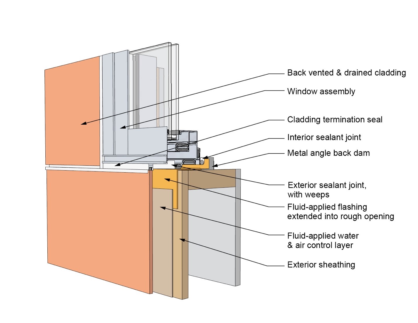
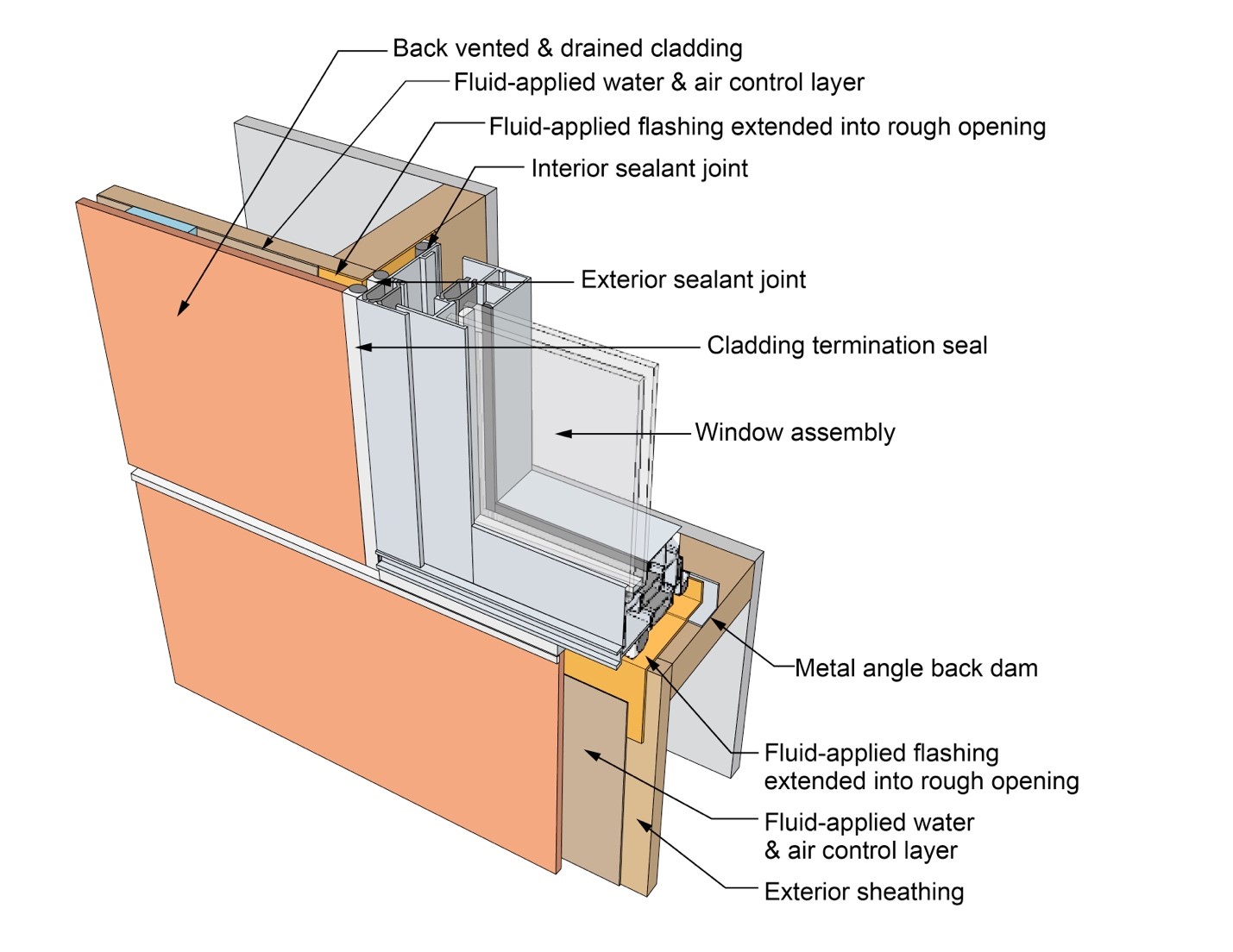
This drawing shows key sill details for a window installation using a fluid-applied flashing on a wall with a fluid-applied water and air control layer
Image
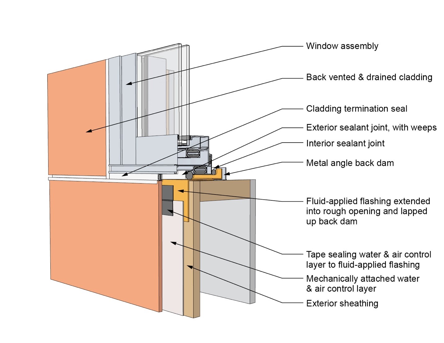
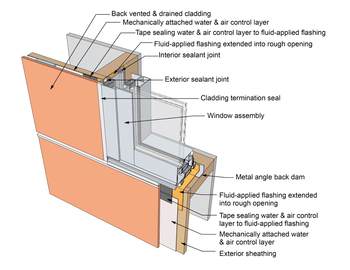
This drawing shows key sill details for a window installation using a fluid-applied flashing on a wall with a mechanically attached water and air control layer
Image
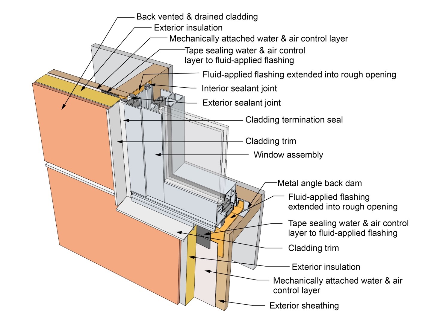
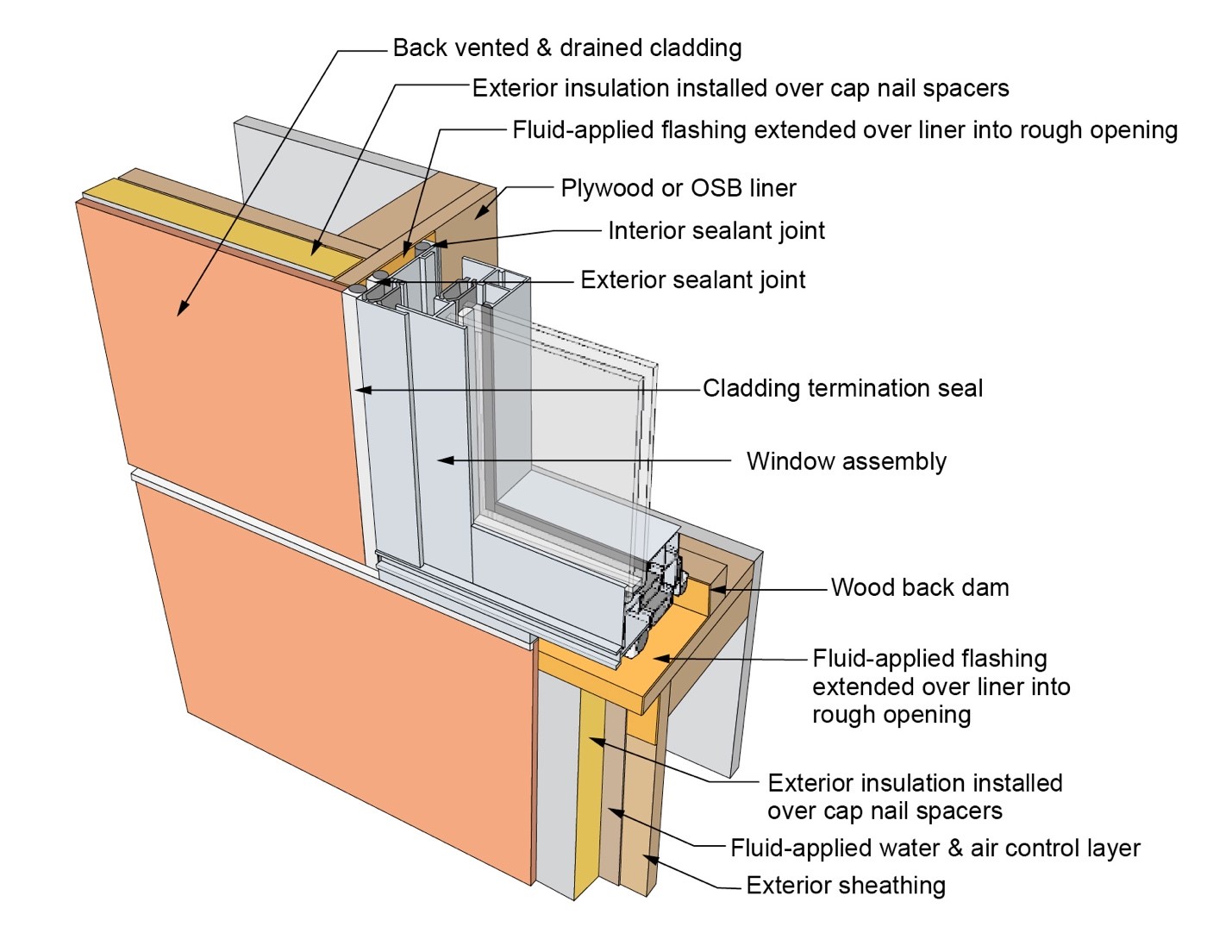
This drawing shows key sill details for a window installation using a fluid-applied flashing on a wall with a mechanically attached water and air control layer and continuous insulation
Image
This drawing shows key sill details for a window installation using a self-adhered membrane tape flashing on a wall with a mechanically attached water and air control layer
Image
This drawing shows key sill details for an “outie” window installation using a fluid-applied flashing on a wall with a fluid-applied water and air control layer and continuous insulation
Image
This farmhouse was retrofit by removing the existing siding and adding taped insulated sheathing and battens before installing new siding
Image
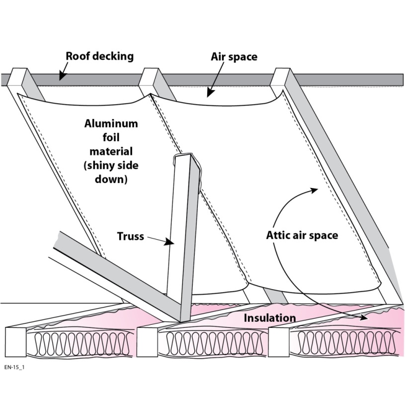
This finished retrofit installation of radiant barrier in attic shows the air spaces at the soffit and ridge to promote attic ventilation
Image
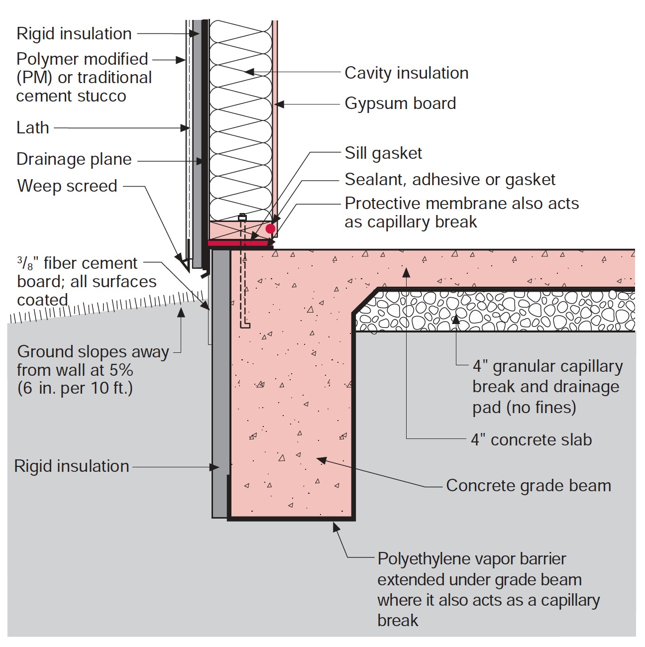
This house design in the Hot-Humid climate uses a slab foundation, masonry walls, and an Exterior Insulation Finish System (EIFS) cladding.
Image
Image
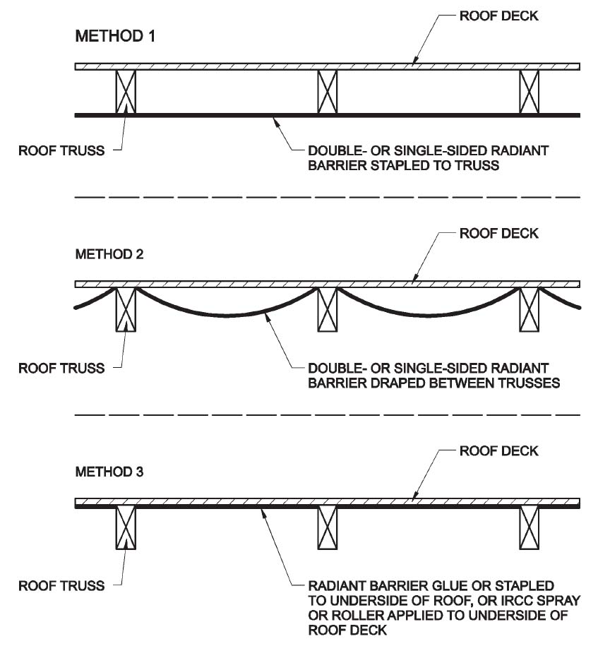
Three locations and methods for installing a roof deck radiant barrier in new construction
Image
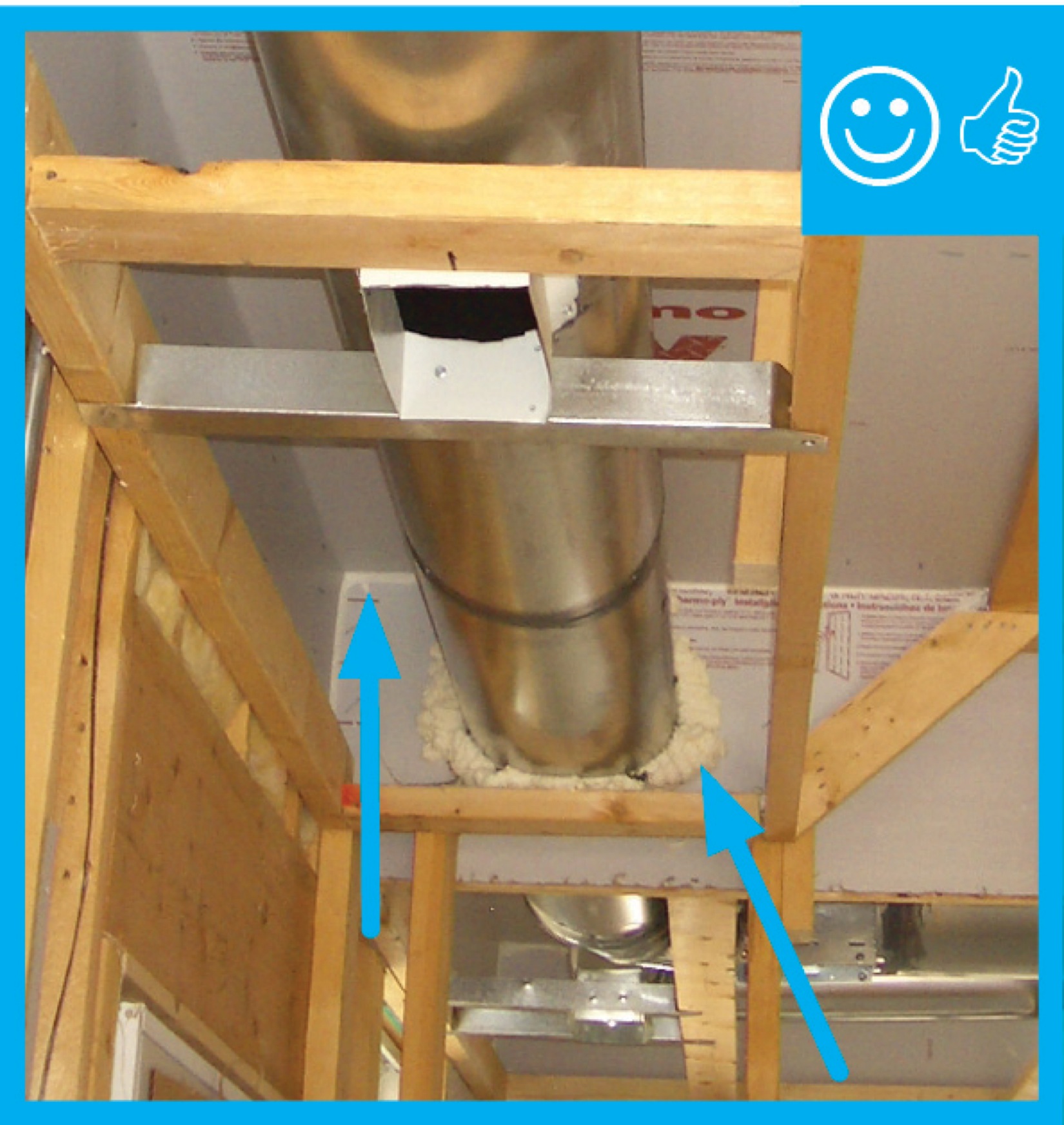
To ensure a complete air barrier between the garage and the house, the wall between the garage and the house was insulated and air-sealed with four inches of high-density spray foam.
Image
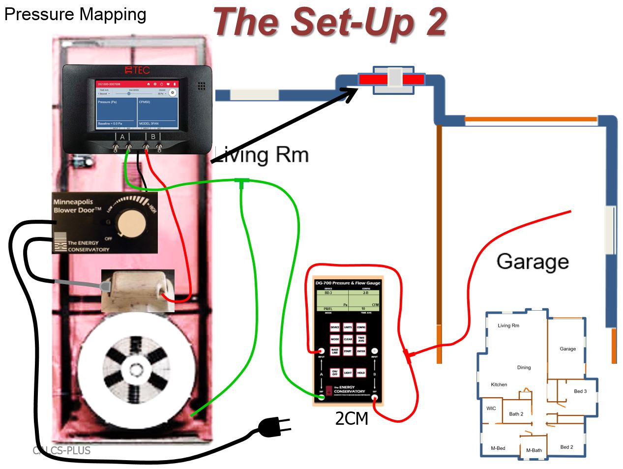
To test house-to-garage airtightness, after connecting the green tubing as shown, connect the red tubing as follows: connect the input tap on channel “A” of the two-channel manometer (2CM) to the reference tap on channel “B” of the 2CM
Image
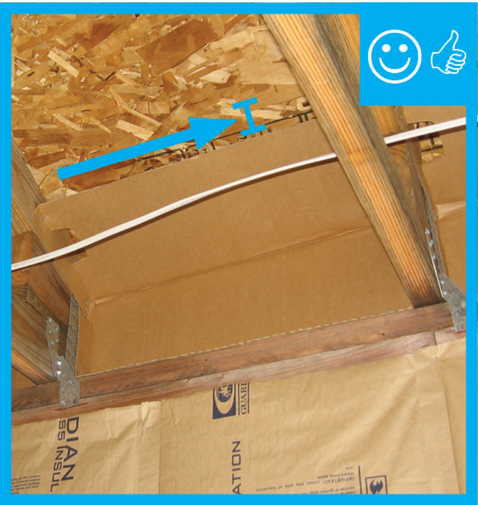
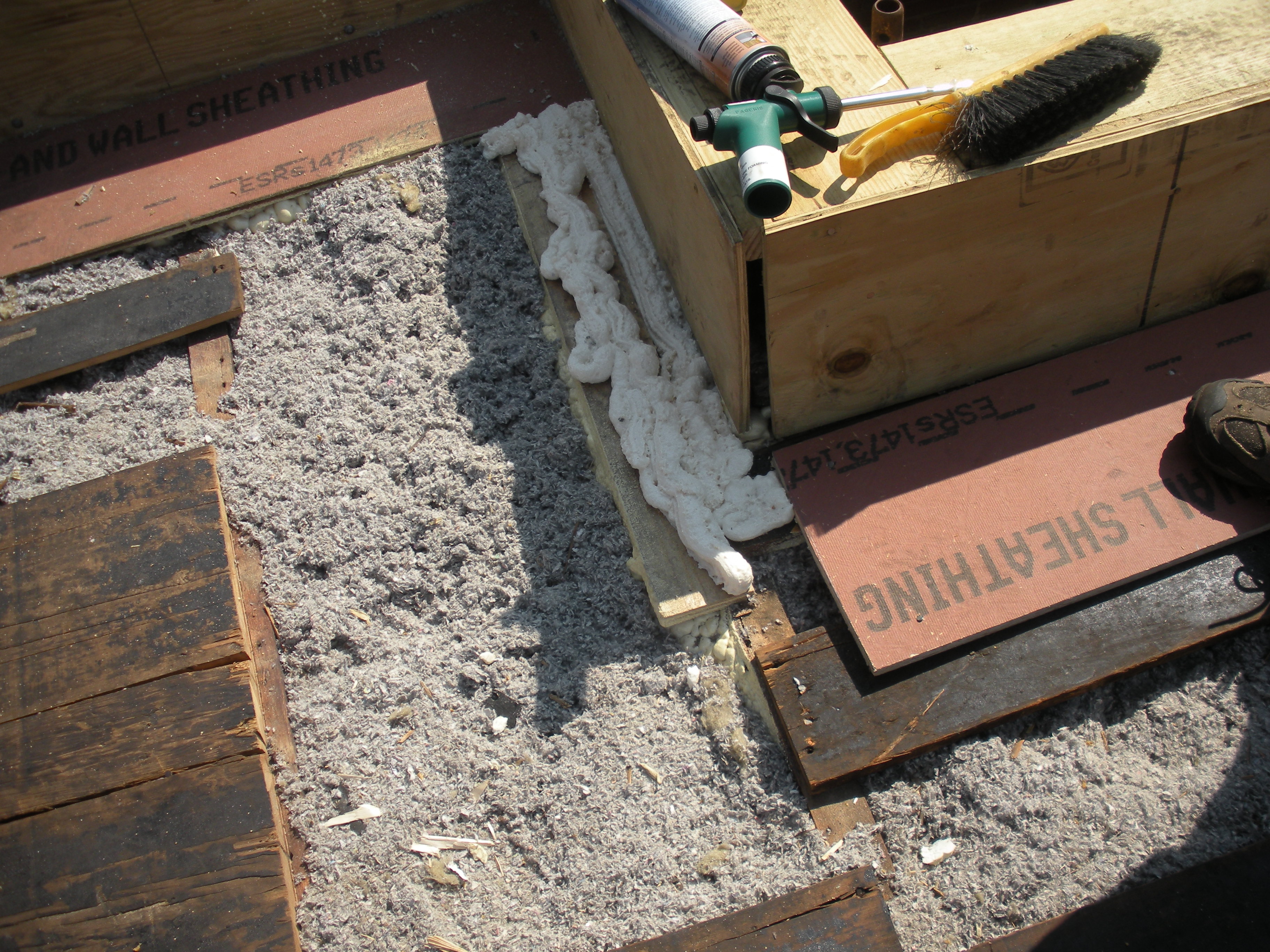
Use caulk or spray foam to air-seal all four edges of the blocking material in each joist bay.
Image
Image
Image
Weather resistant barrier is wrapped over the edge from roof to wall sheathing to provide a continuous air barrier at this transition.
Image
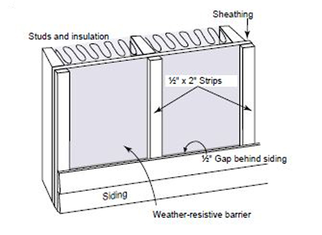
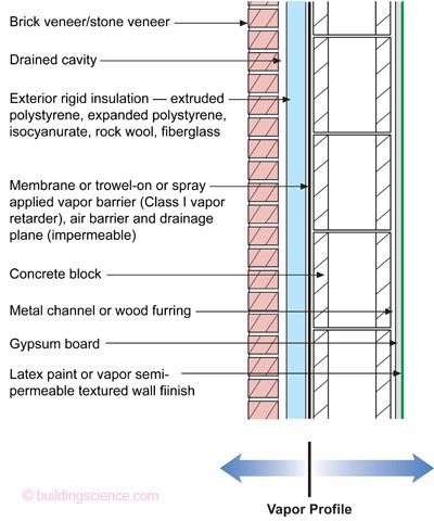
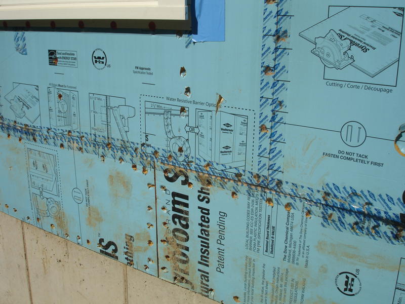
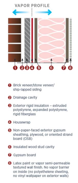
When rigid foam insulation is applied to the exterior side of the wall cavity under the cladding, with seams taped and an air gap provided, it acts as a vapor barrier, air barrier, and rain screen.
Image
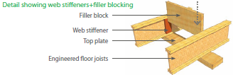
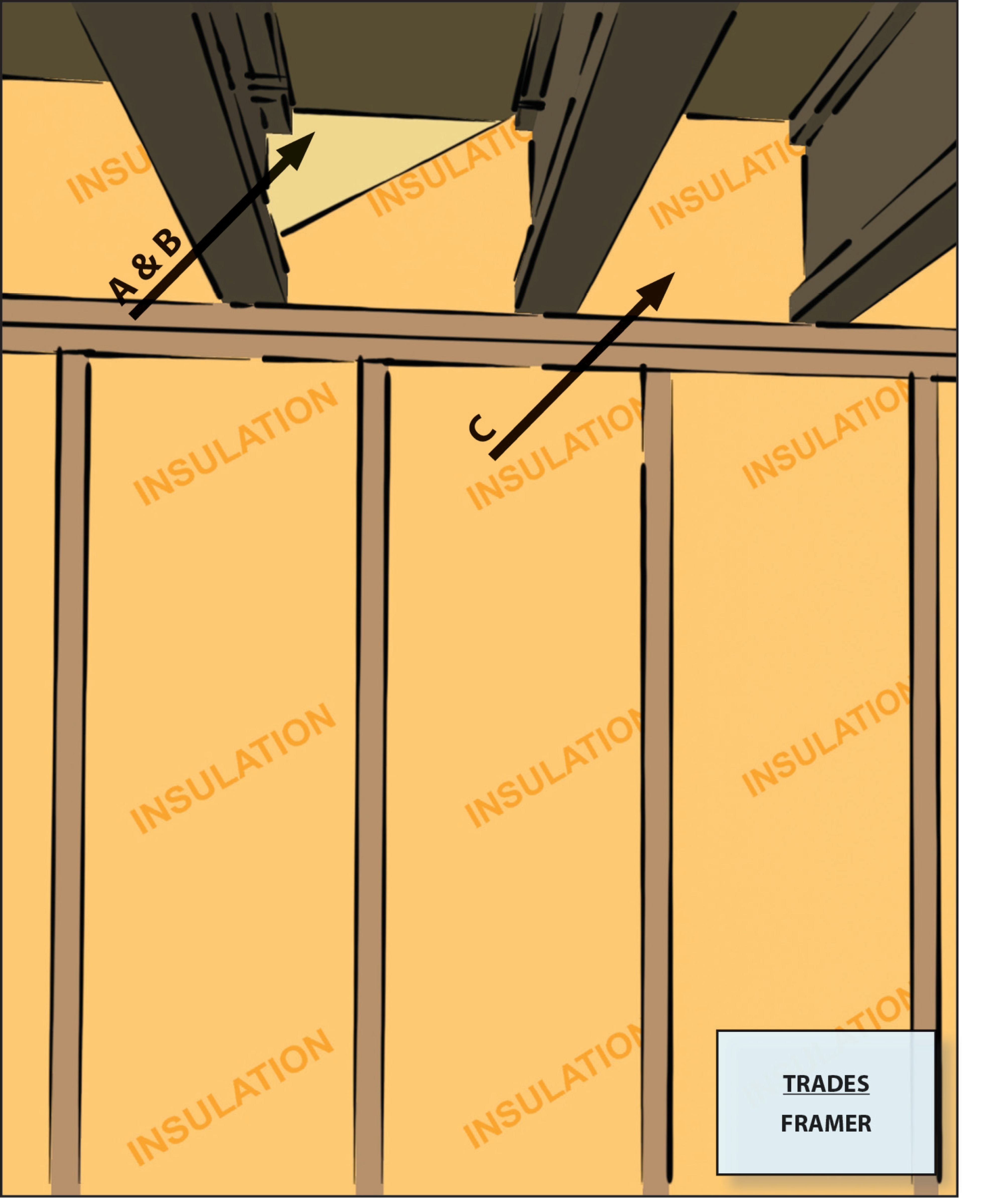
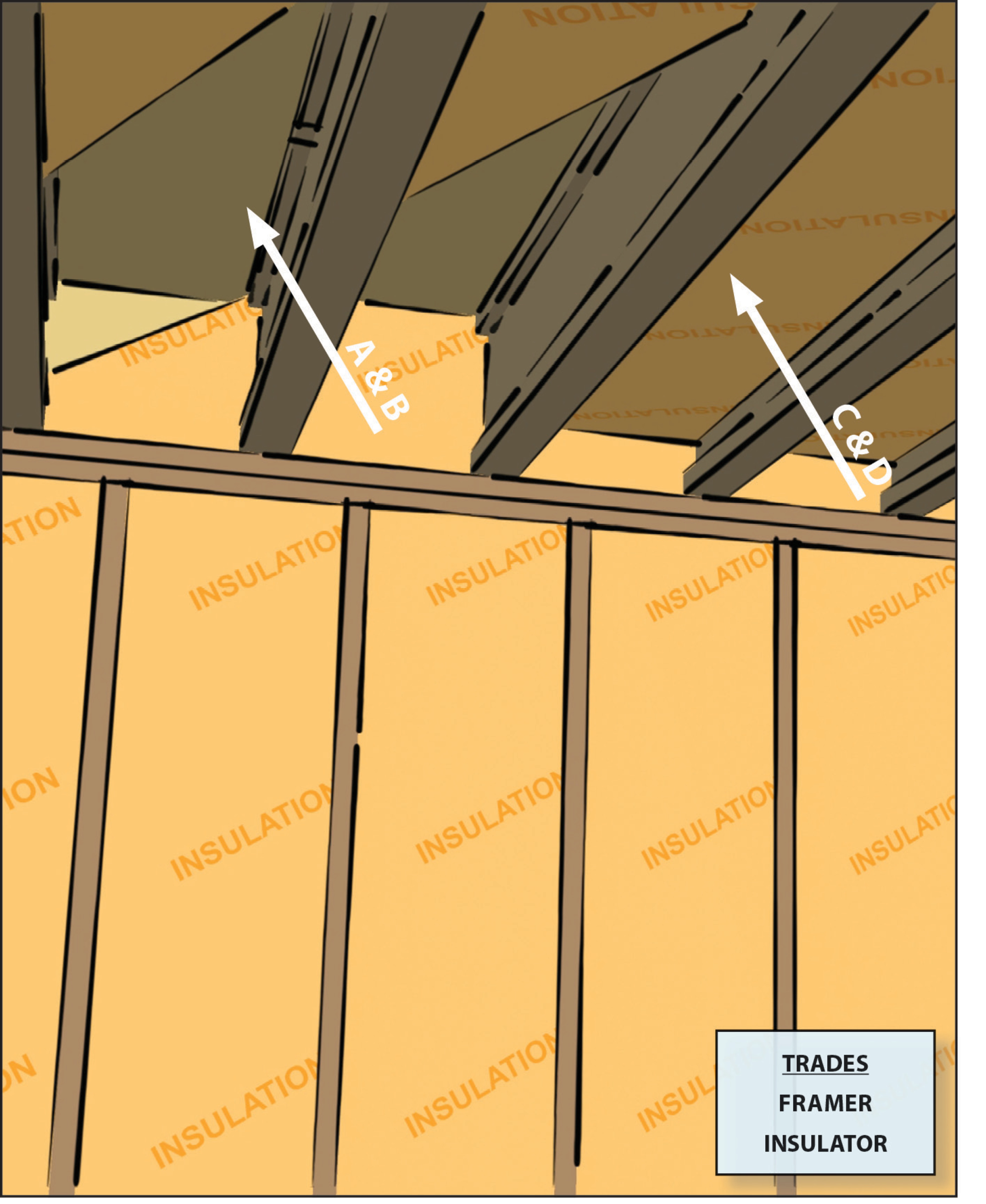
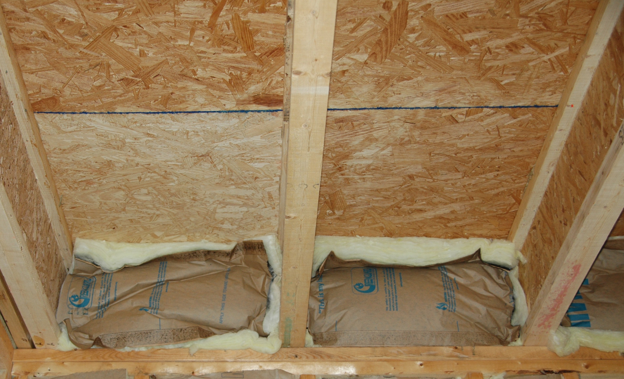
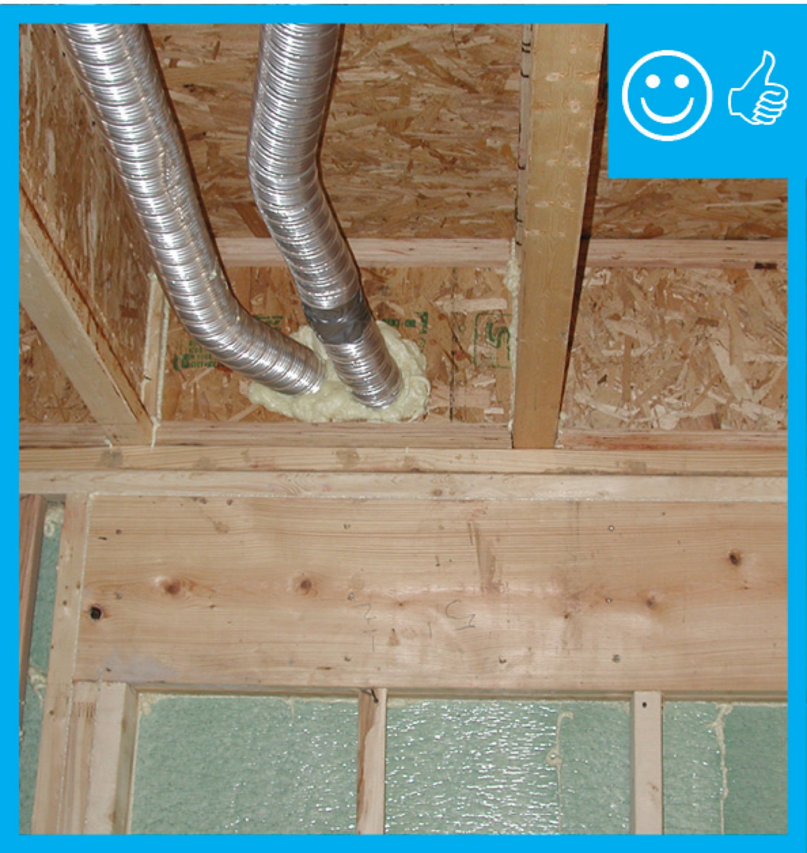
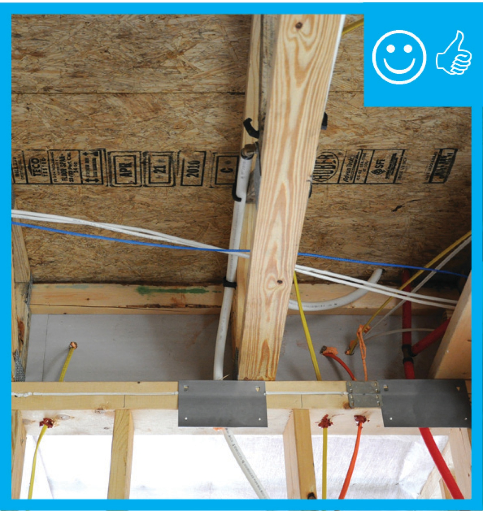
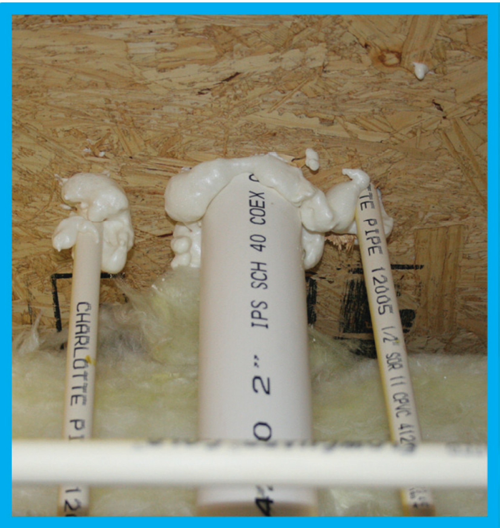
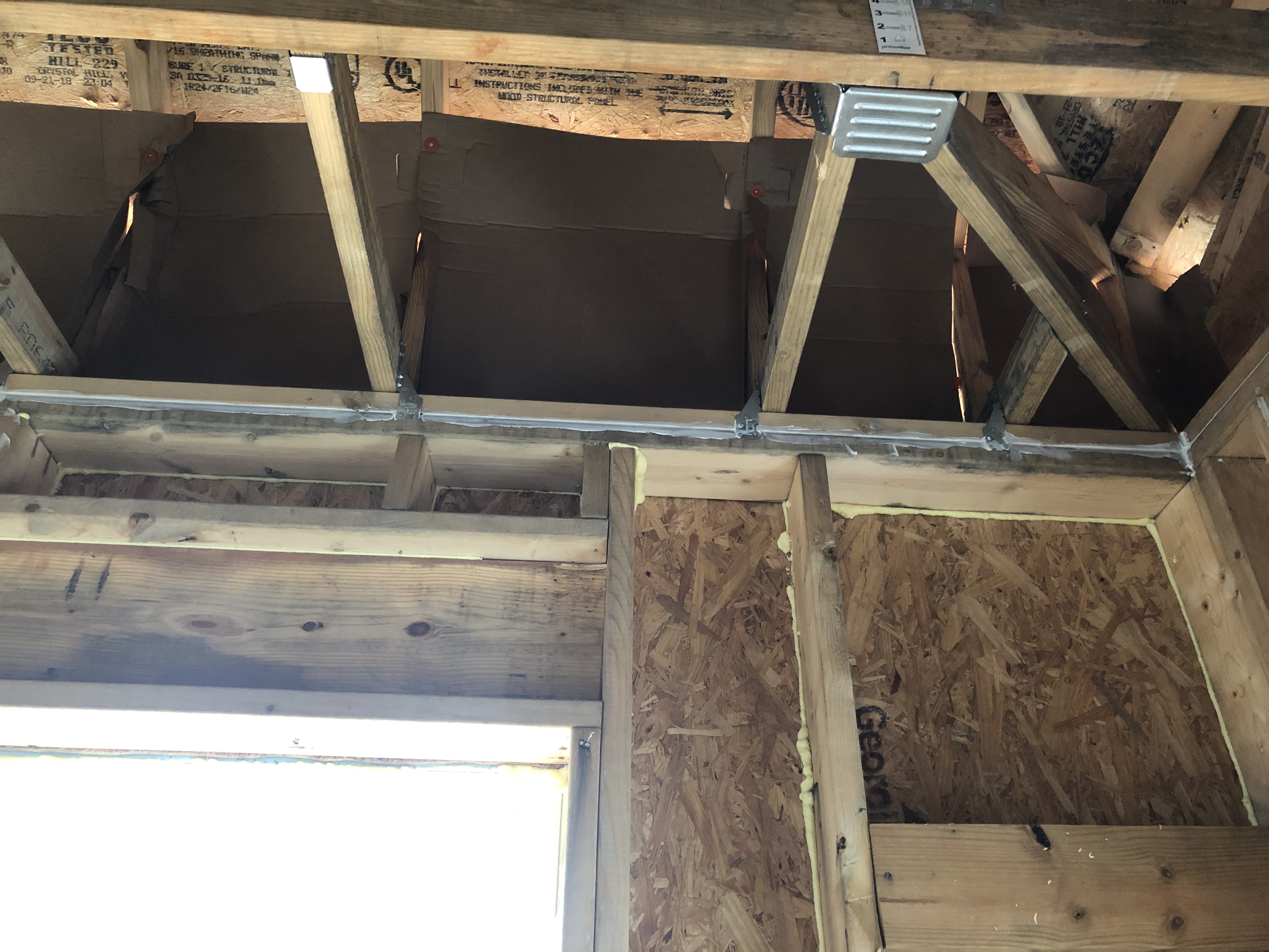
When using I-joists, make sure to fill in the gaps on each side of the blocking material to air-seal the joist bay where a wall separates conditioned and unconditioned spaces.
Image
Windows are installed as “outies” in this wall assembly using a self-adhered membrane water and air control layer with continuous exterior insulation
Image
Image
Image
Image
Image

Image
Image
Image

Image
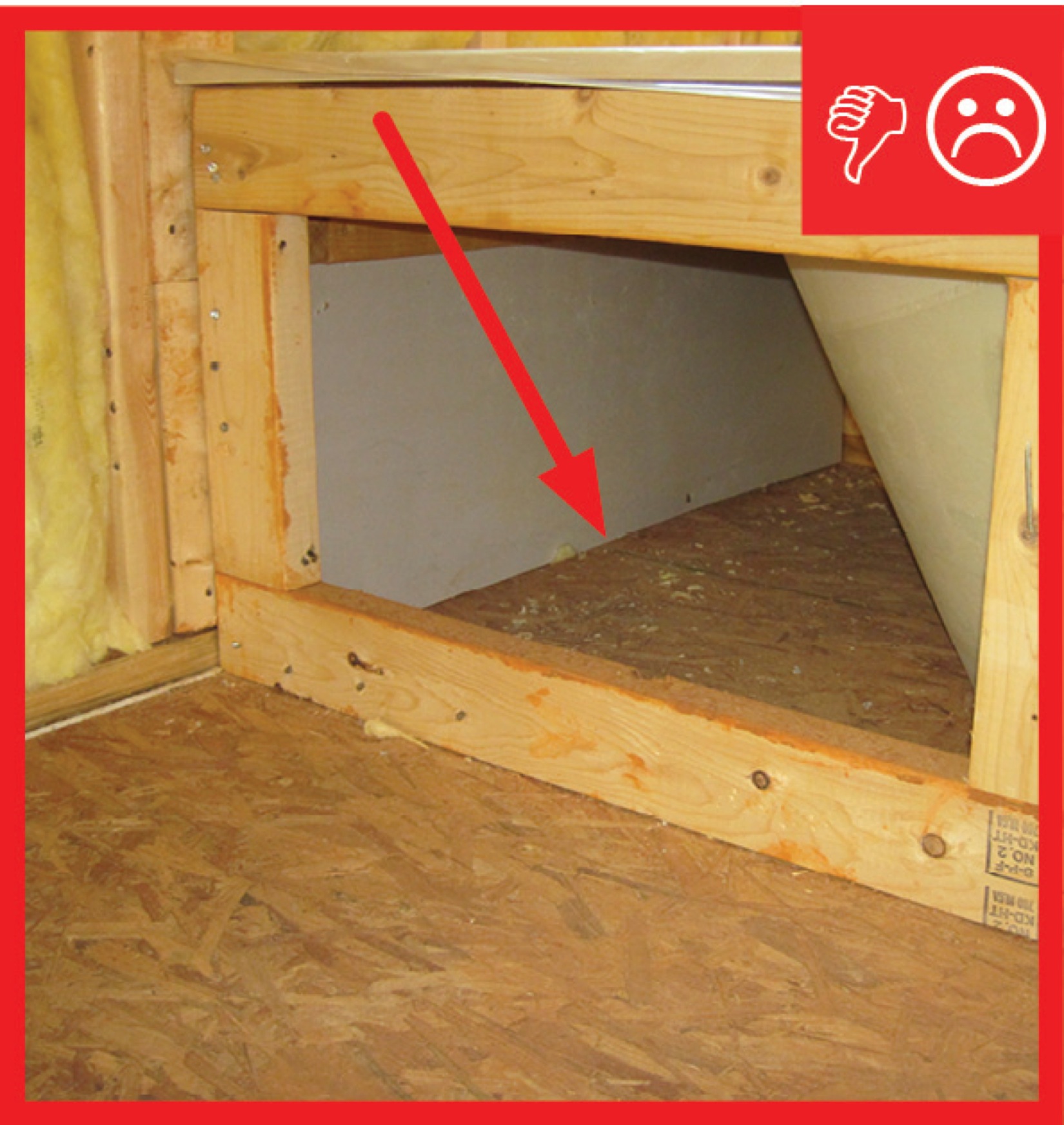
Wrong - Cantilevered floor joist bay cavities are not air sealed with a solid air barrier aligned with the exterior wall.
Image
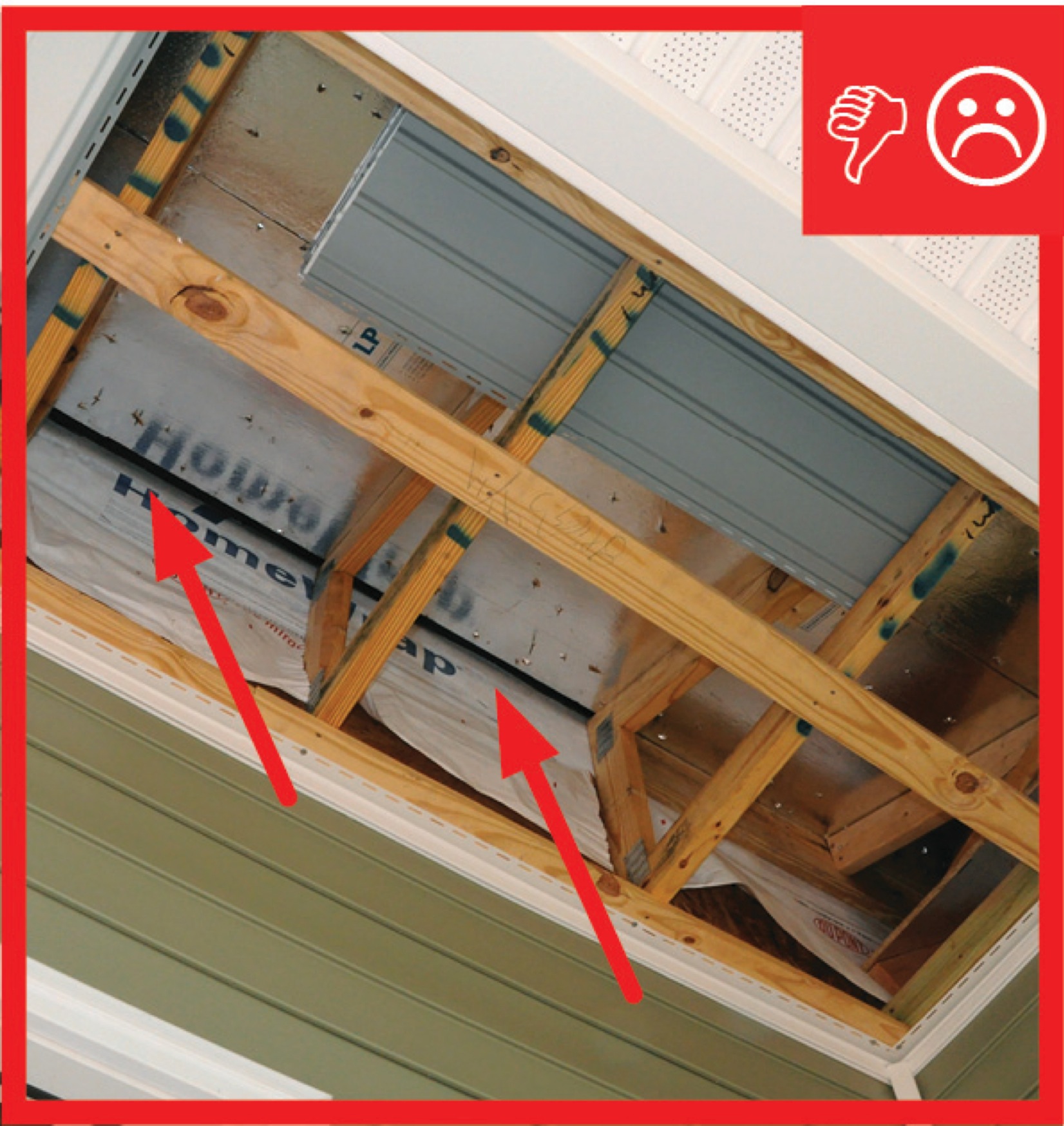
Wrong - Cantilevered joist bay cavities are not air sealed with a solid air barrier, allowing outside air to flow between floors.
Image
Image
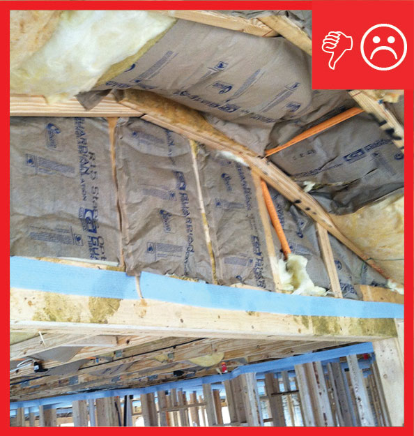
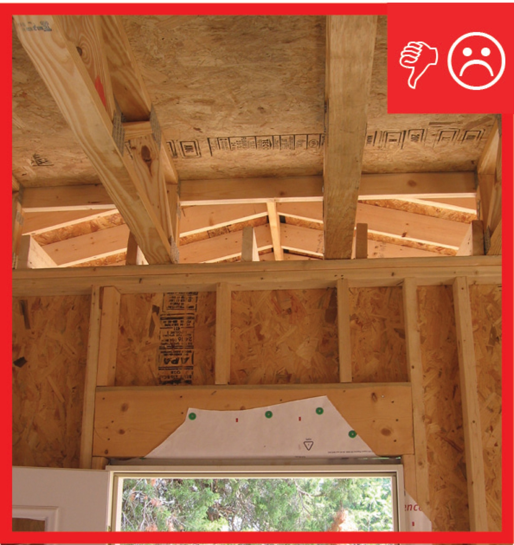
Wrong - Ceiling insulation is not completely installed and air barrier is missing.
Image
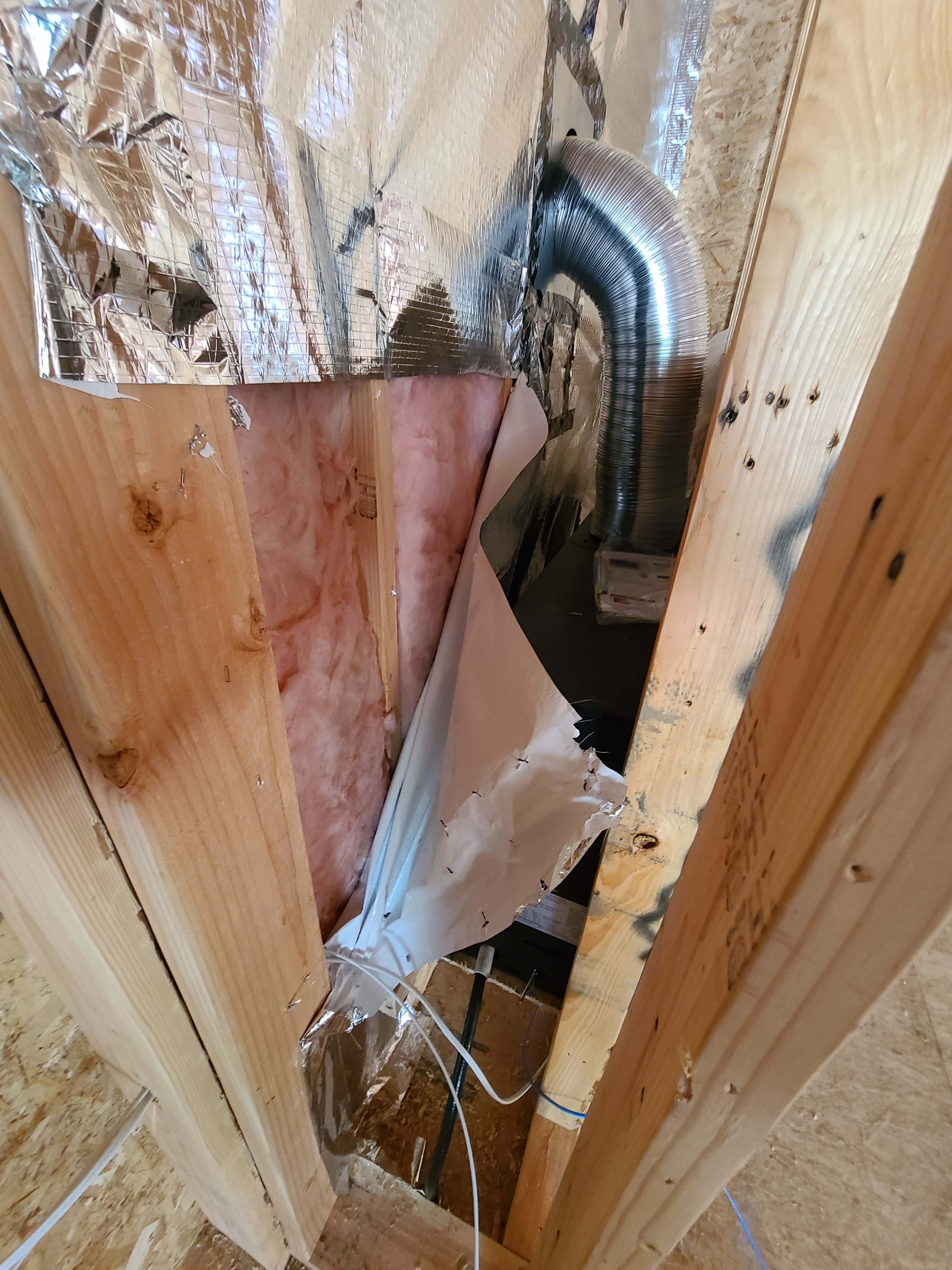
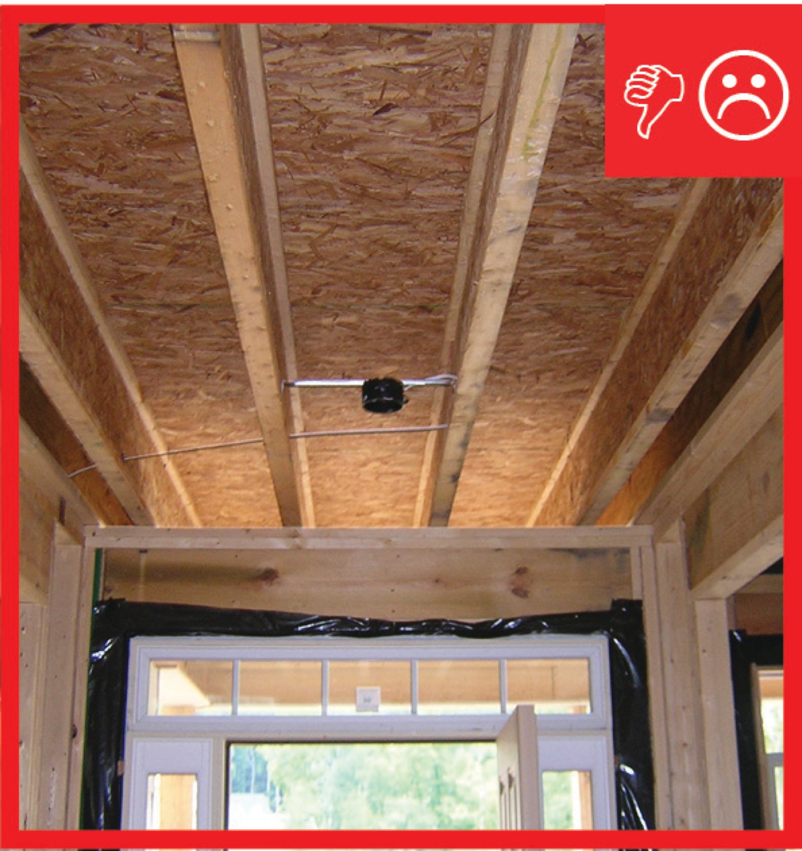
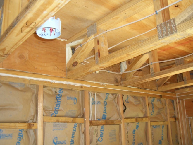
Wrong - Foil air barrier was ripped to install wiring; foil should be replaced with a solid air barrier and wiring hole should be caulked.
Image
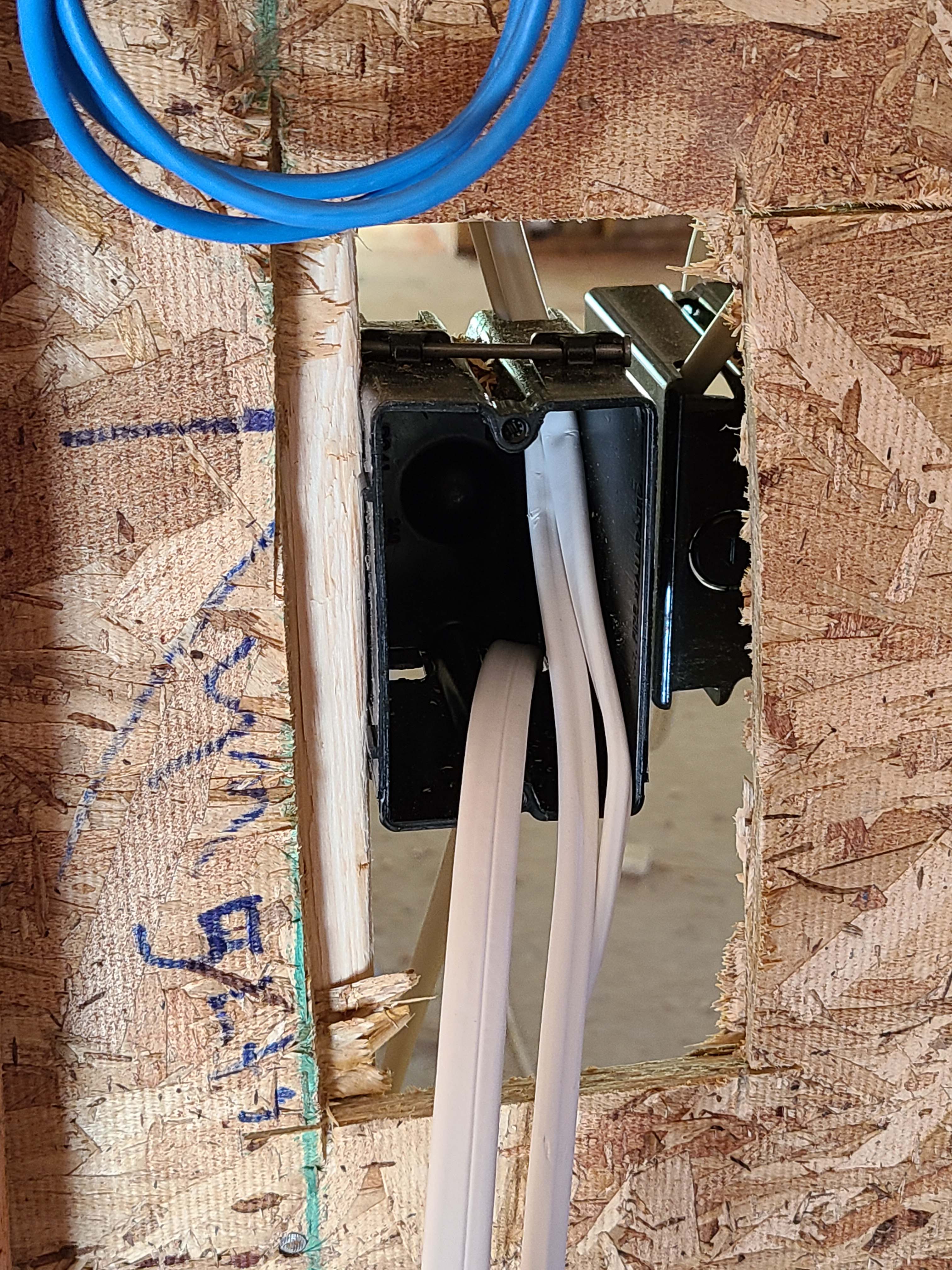
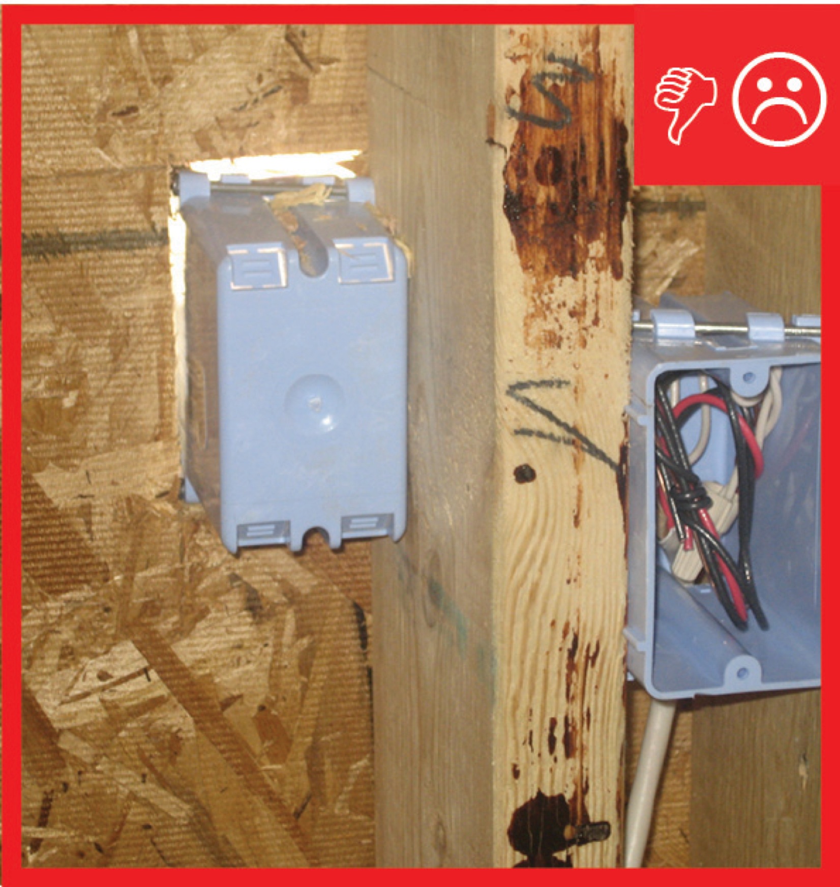
Wrong - Hole around electrical box is cut too large; gap needs to be air-sealed.
Image
Image
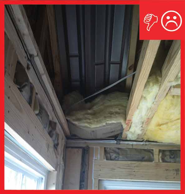
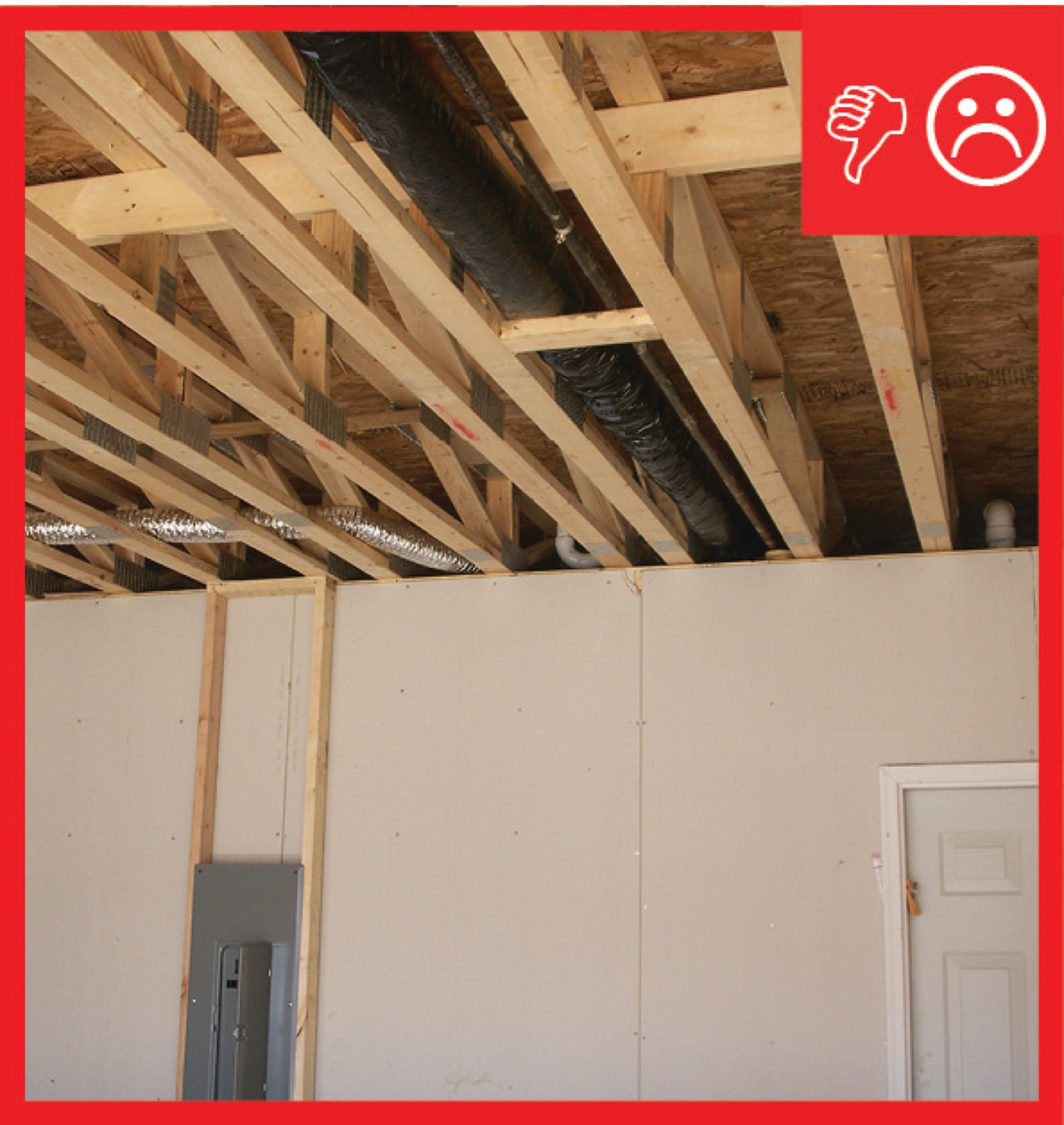
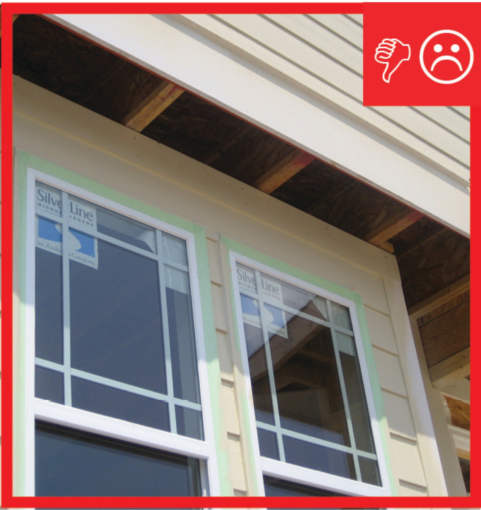
Wrong - No air barrier is present between the dropped ceiling/soffit and the attic.
Image

Wrong - No air barrier is present between the dropped ceiling/soffit and the attic.
Image
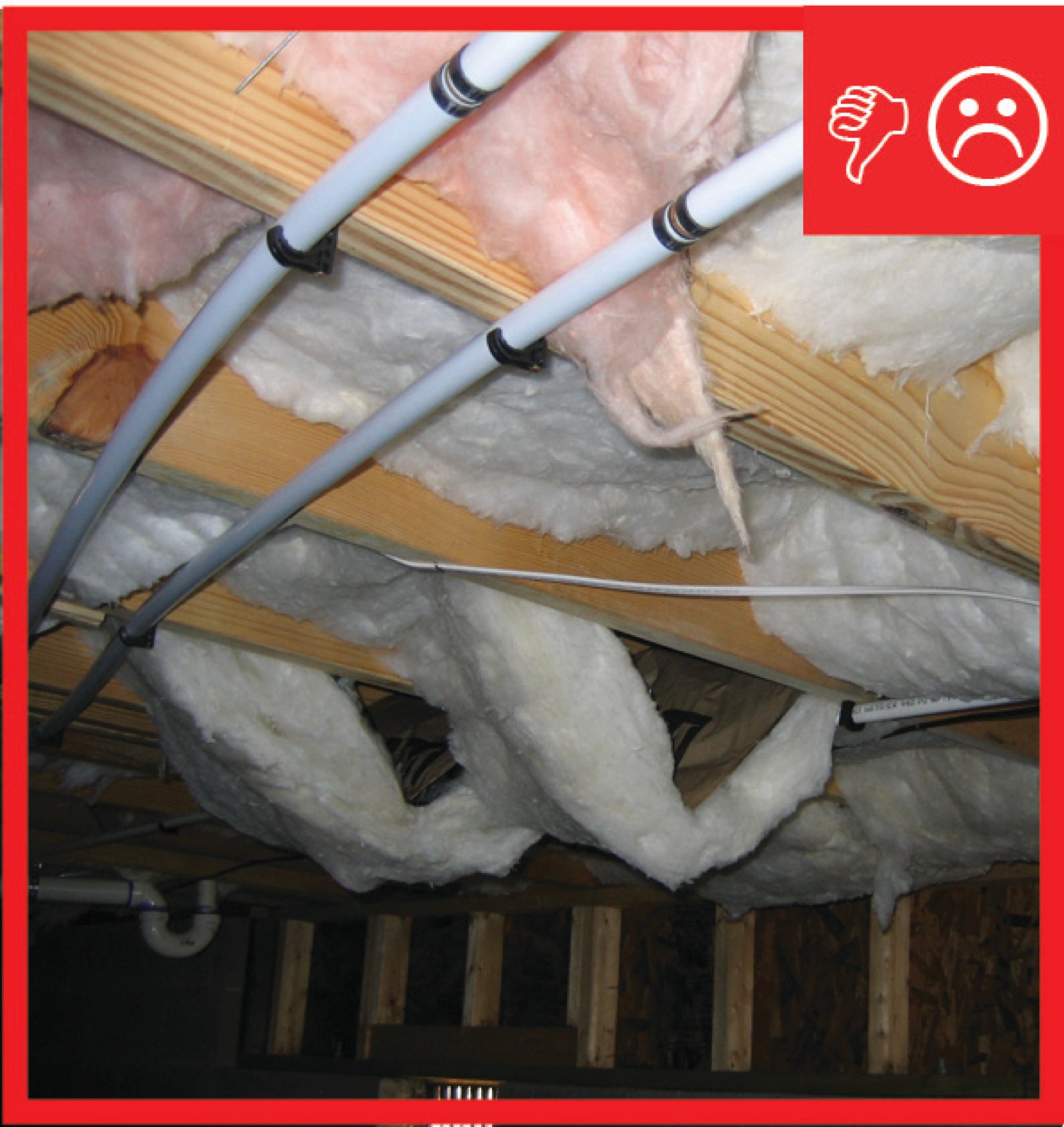
Wrong - No air barrier is present between the floor system and unconditioned space.
Image

Image
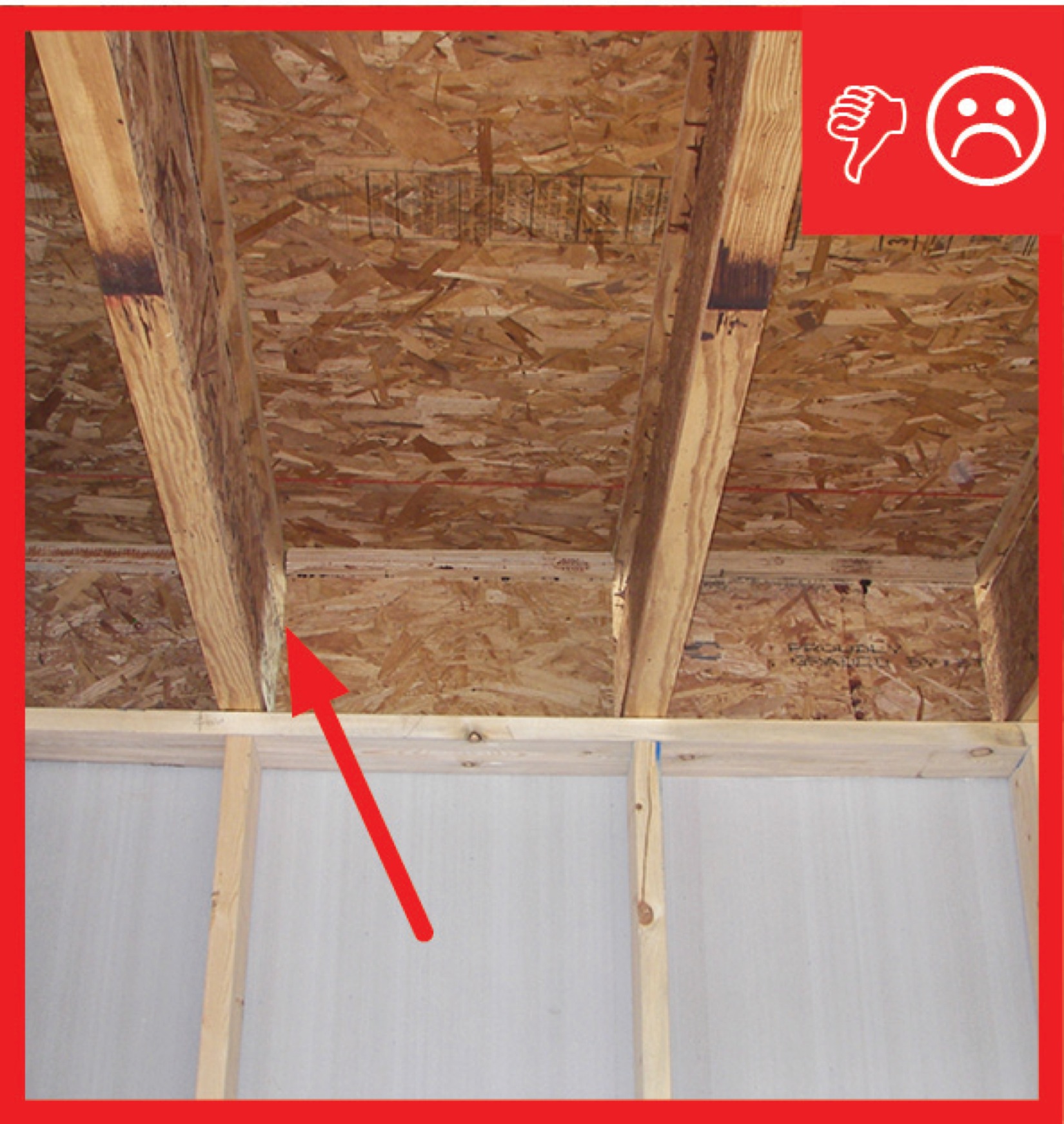
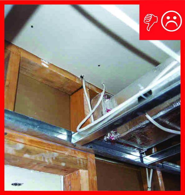
Wrong - No air barrier is present in the floor joists spanning over the garage and conditioned space of the home.
Image
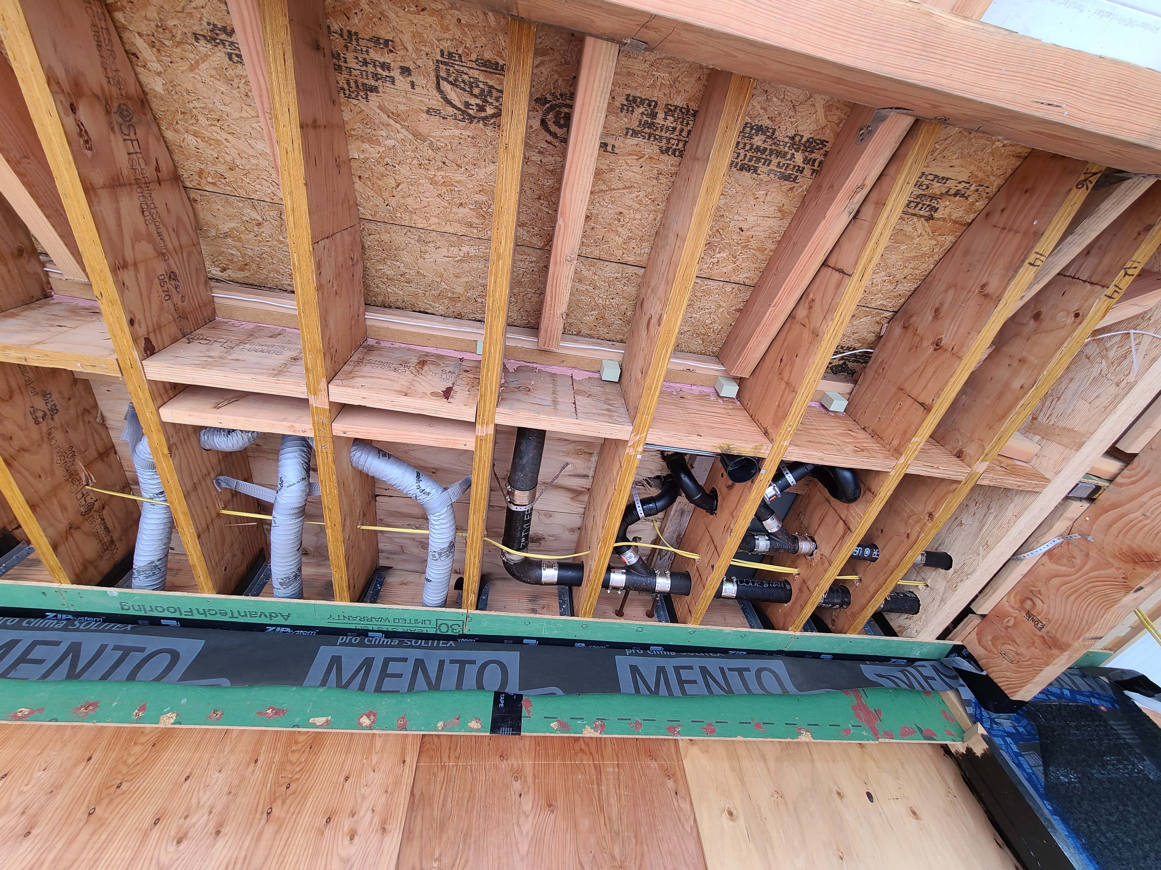
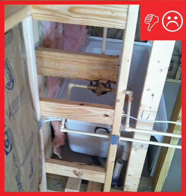
Wrong - Plumbing penetrations are not sealed in sub-floor and it is not recommended to run plumbing in a cantilevered floor.
Image
Image
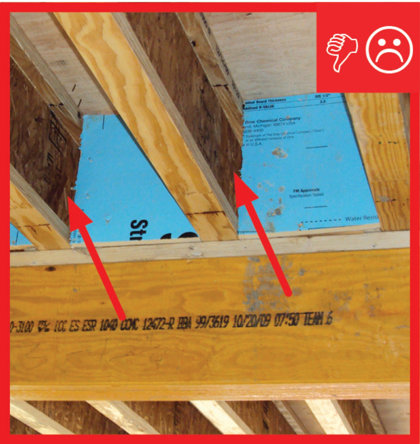
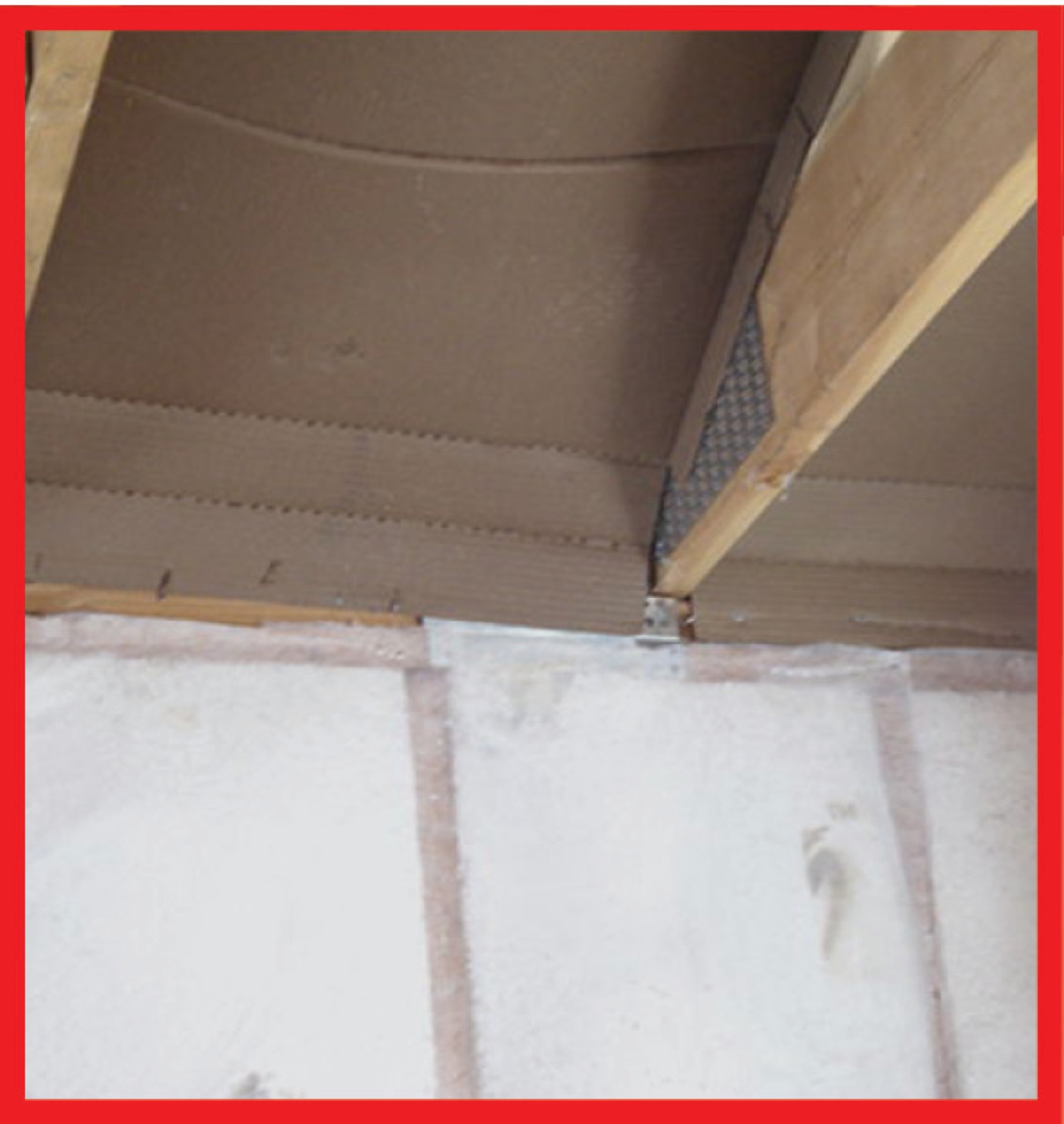
Wrong - Rigid insulation blocking is installed but not air-sealed with spray foam around edges.
Image
Image
Image
Image
Wrong - The air barrier is not sealed (picture taken from garage looking into house).
Image
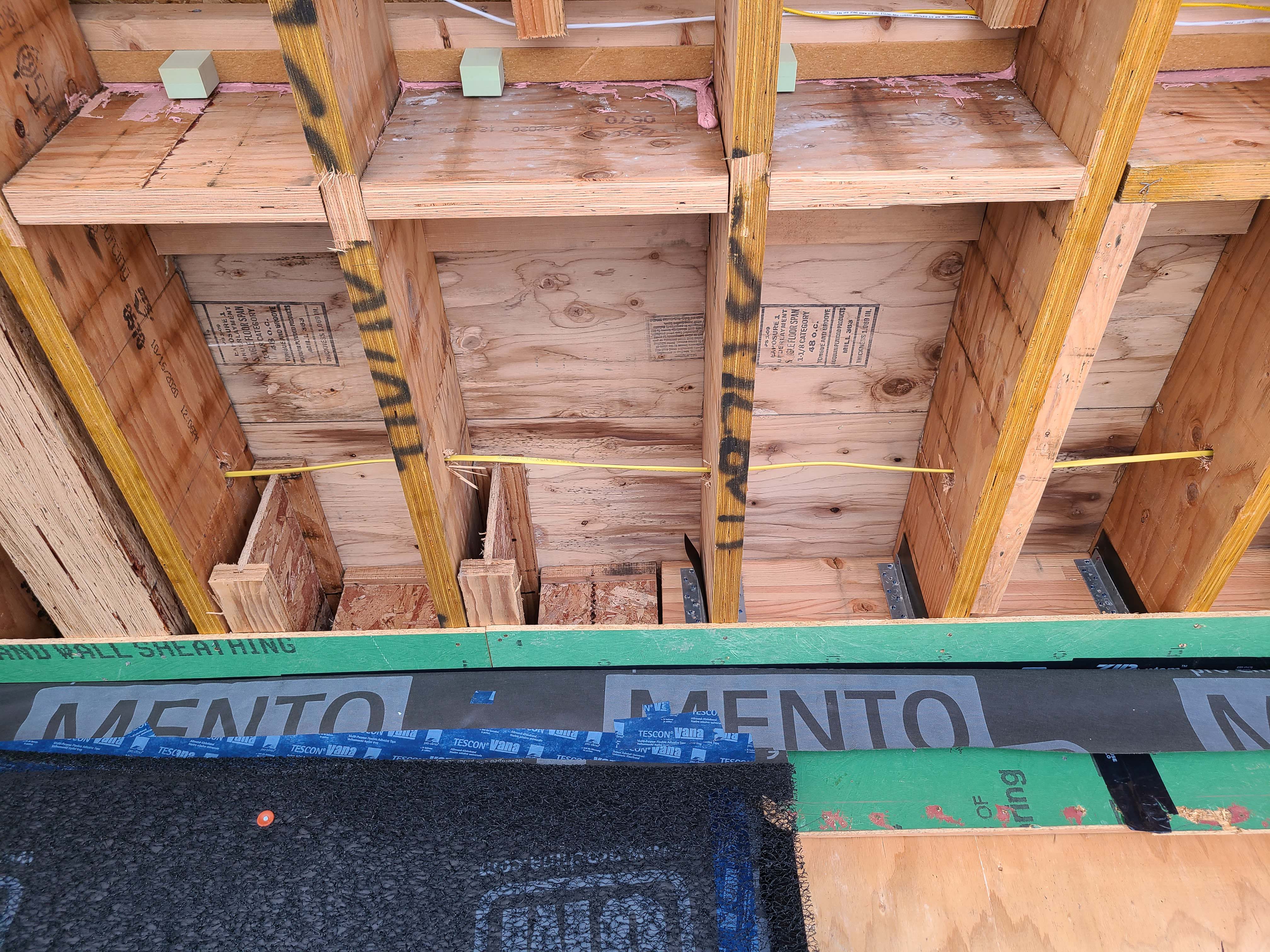
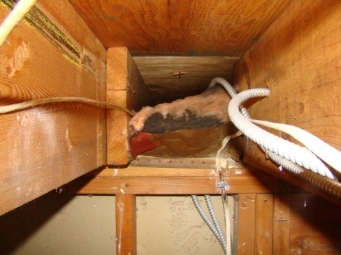
Wrong - The band joist above this garage-house shared wall is not properly sealed.
Image
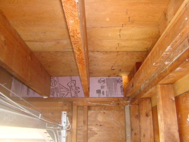
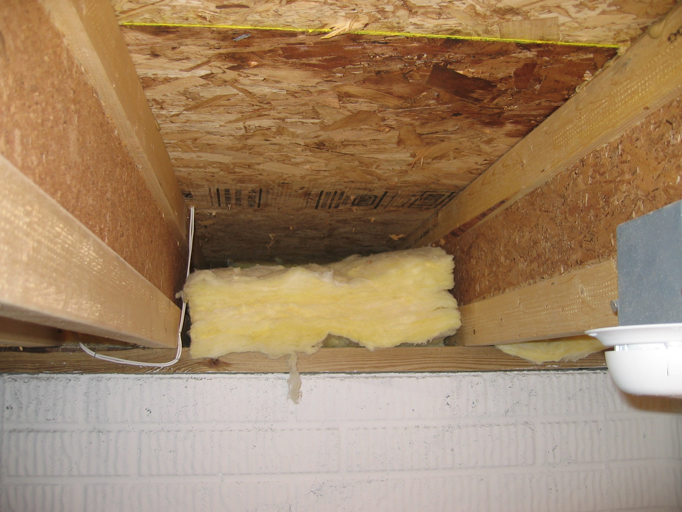
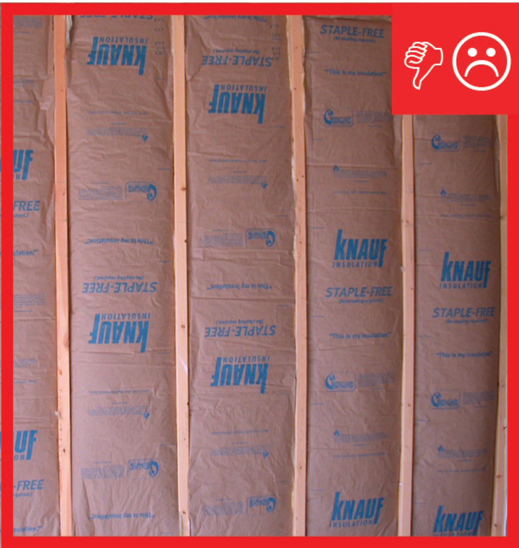
Wrong - The faced batt insulation does not provide an air barrier in the joist bay between the garage and the conditioned space of the home.
Image
Wrong - The rigid foam that was installed as an air barrier at the rim joist was not properly air-sealed.
Image
Image
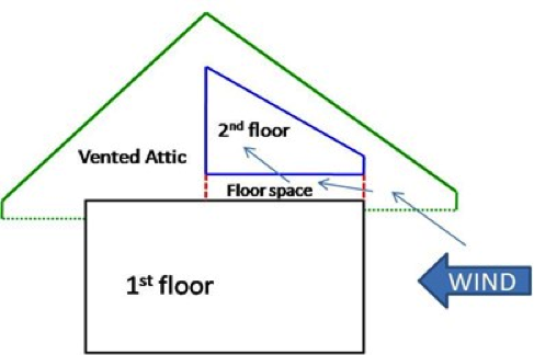
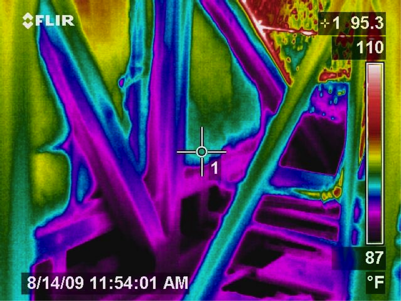
Wrong - This IR image of a second-floor landing shows that attic air is flowing far into the interstitial floor cavity of the second-floor landing
Image

Wrong - This IR image shows where hot attic air has penetrated into the floor cavity that lies behind the stairwell wall
Image
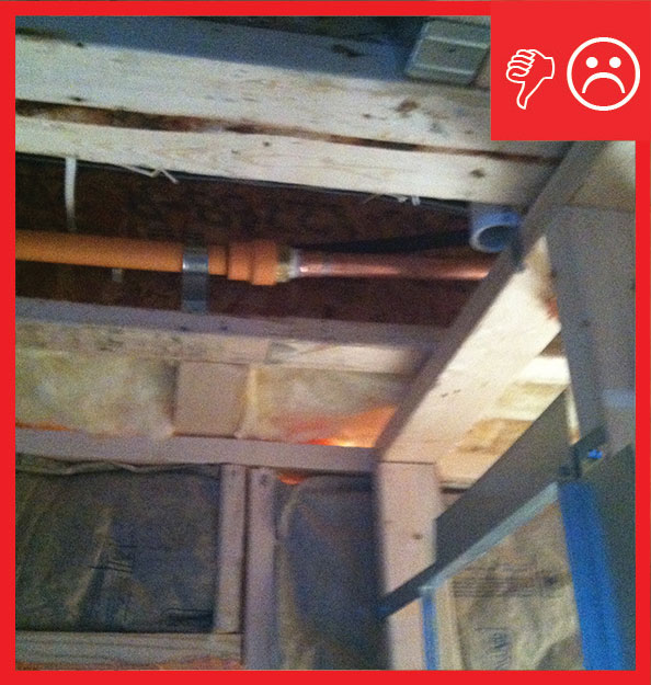
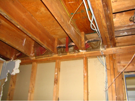
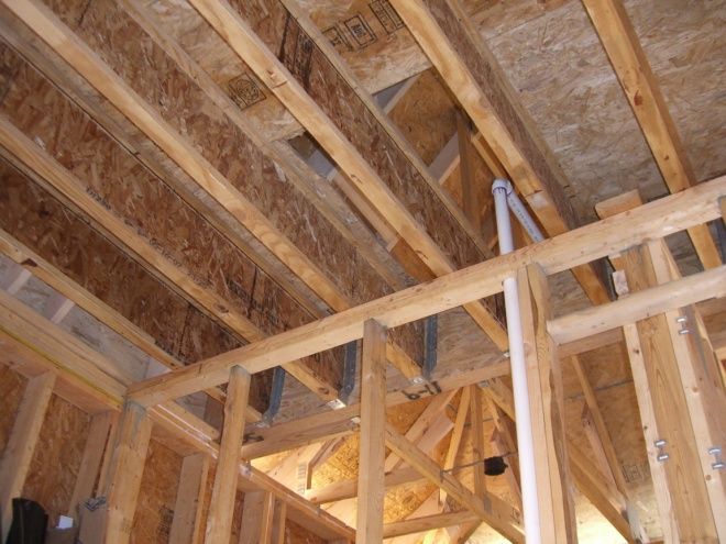
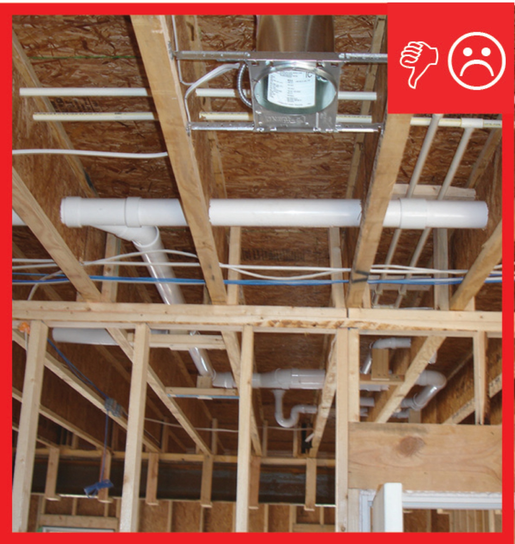
Wrong - This is a poorly sealed chase with no solid air barriers along the sides of the chase and no caulk around the electrical wires installed through the ceiling of the chase.
Image
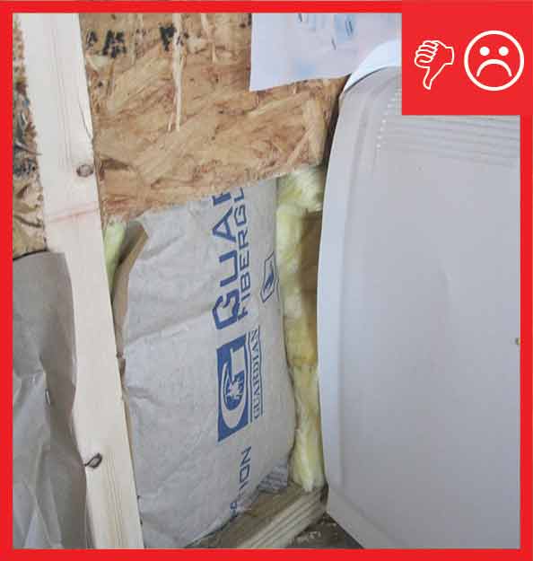
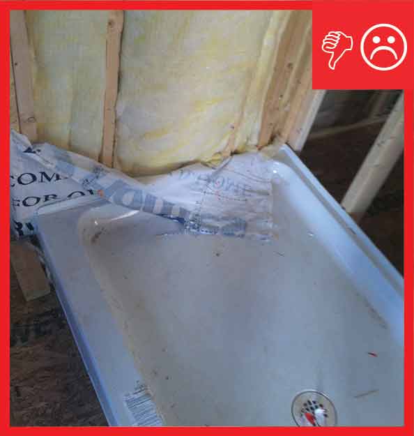
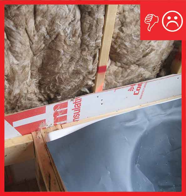
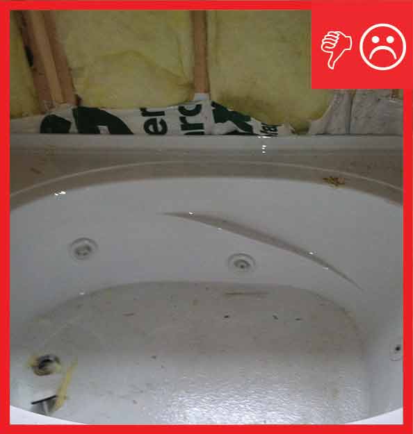
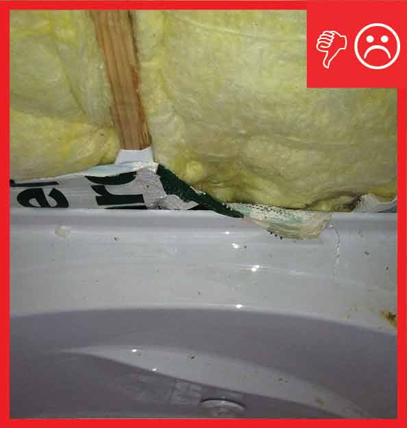
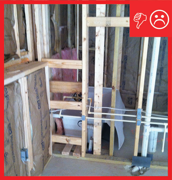
Wrong - Tub or shower floor is not insulated and air-sealed with a solid barrier material between the floor joists and the tub. Plumbing pipes shouldn't be located in a cantilever.
Image
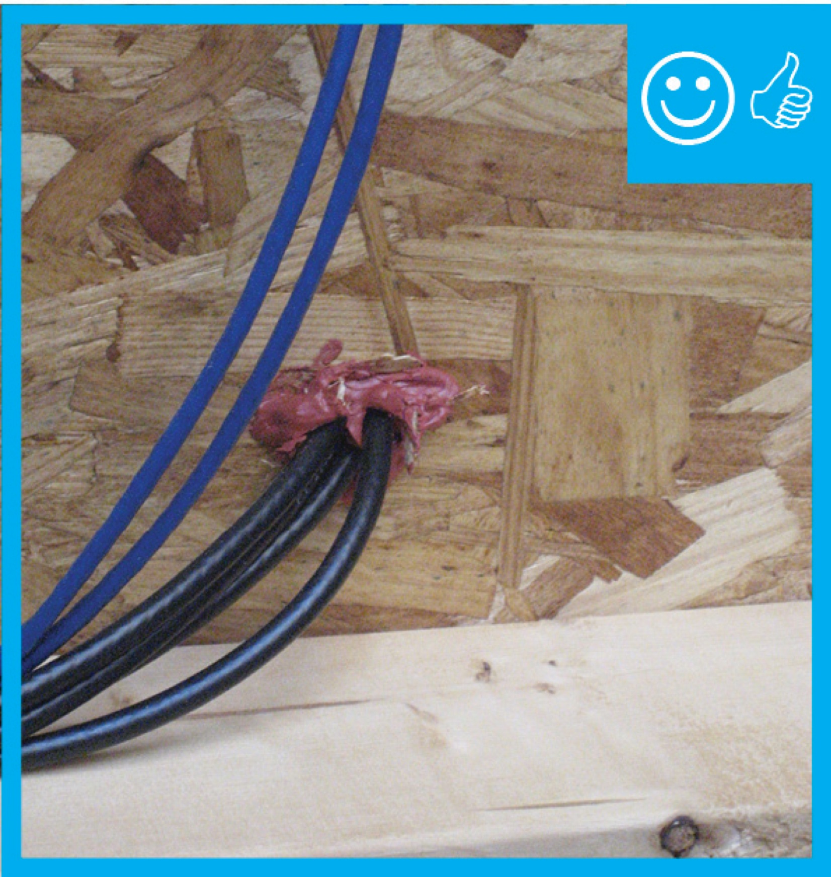
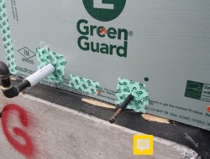
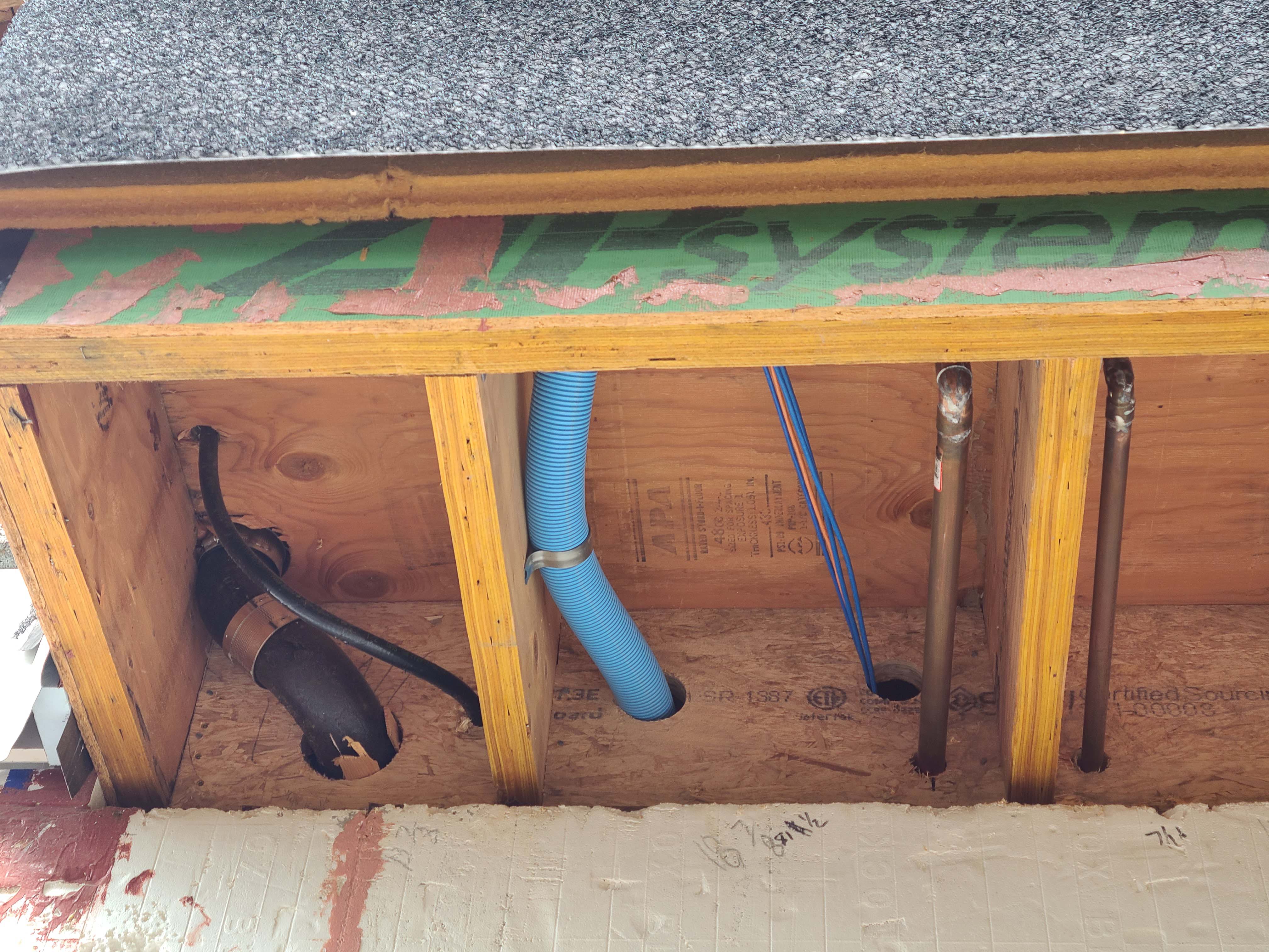
Wrong - Unsealed holes for pipes can leave gaps large enough for insects, rodents, and even birds to enter the home.
Image
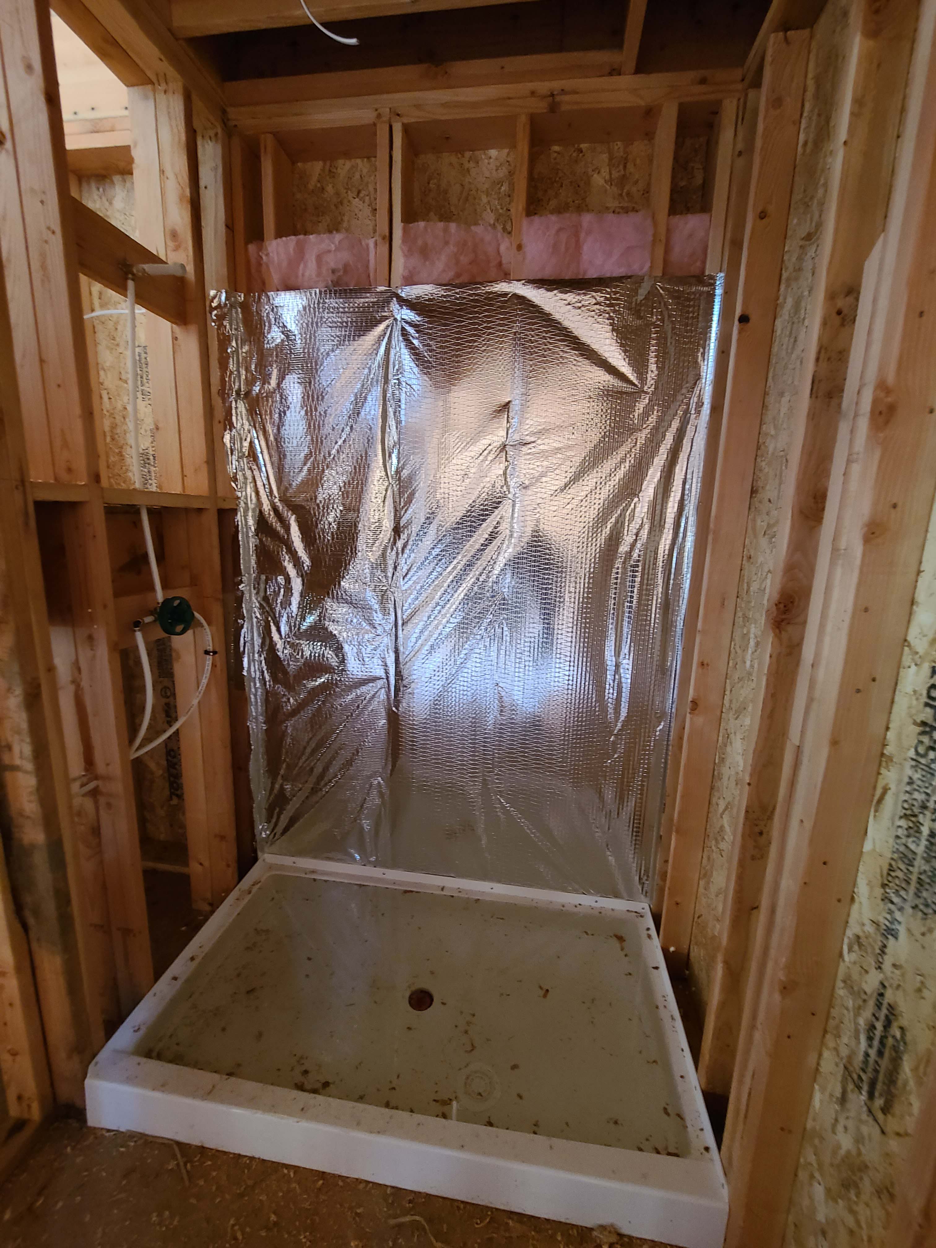
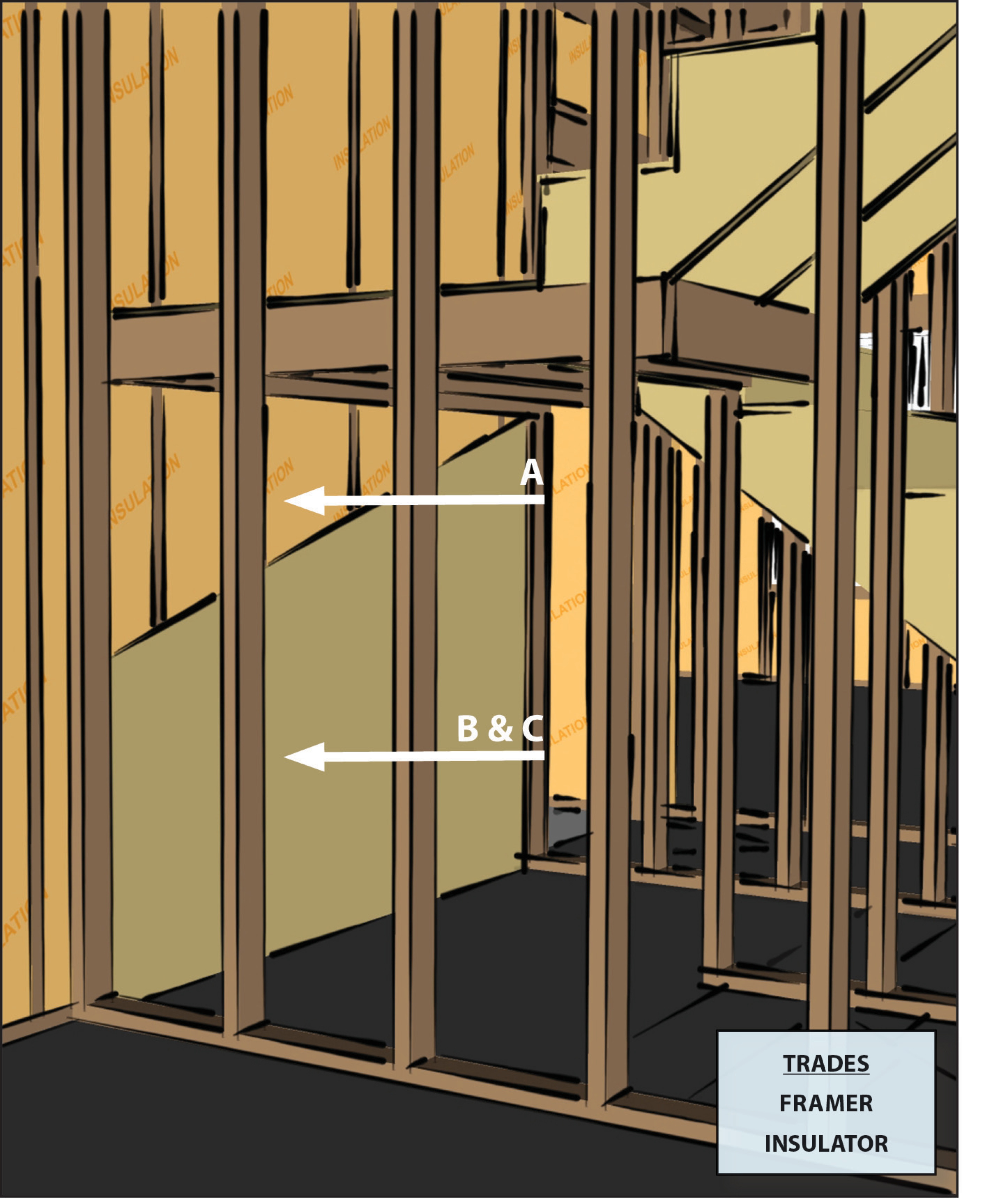
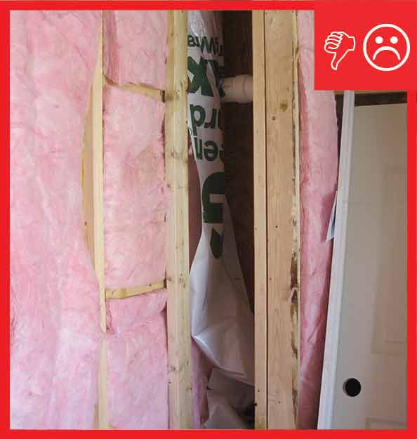
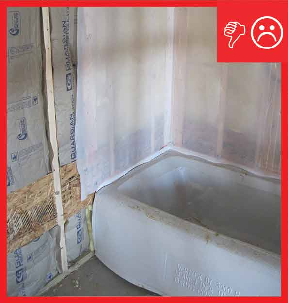
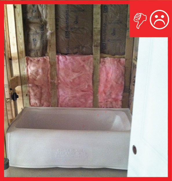
Wrong - Wall cavities behind shower are not completely filled with insulation and are lacking the solid interior air barrier.
Image
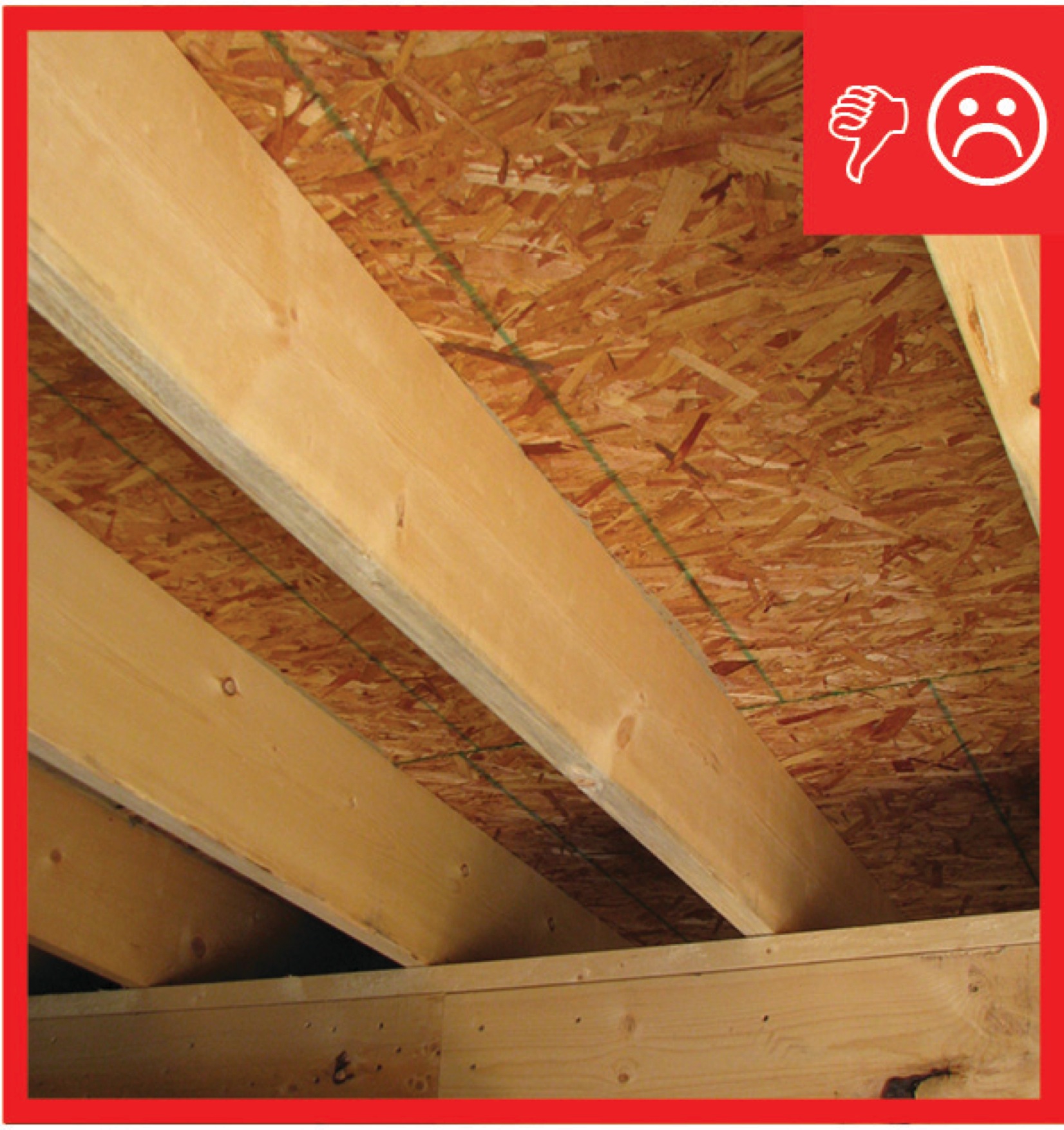
Wrong - When ceiling joists over a garage run perpendicular to the adjoining wall, the joist bays must be blocked and sealed to prevent garage fumes from entering the living space
Image
Image
Image
Image

Image
Image
Image
Image
Image
Image
Image
Image
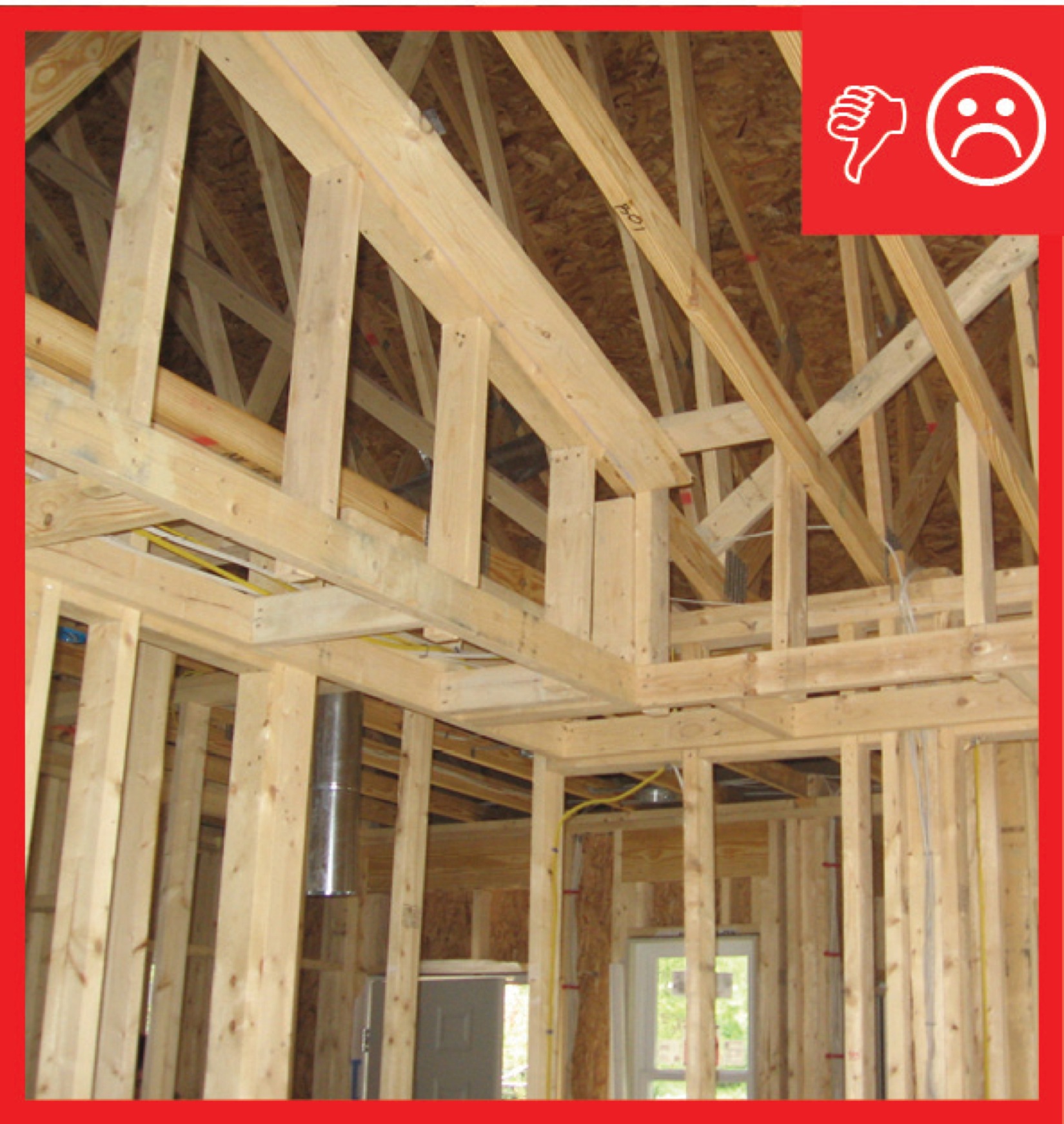
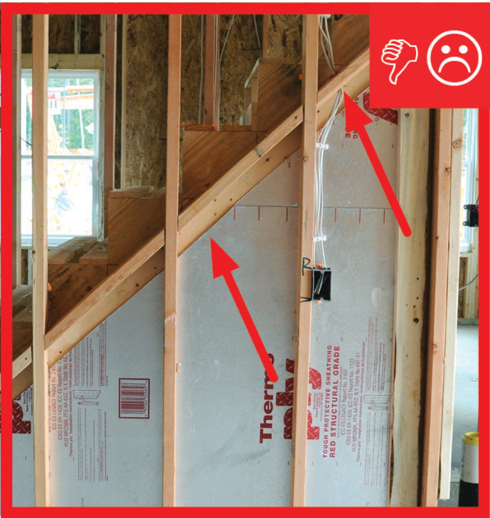
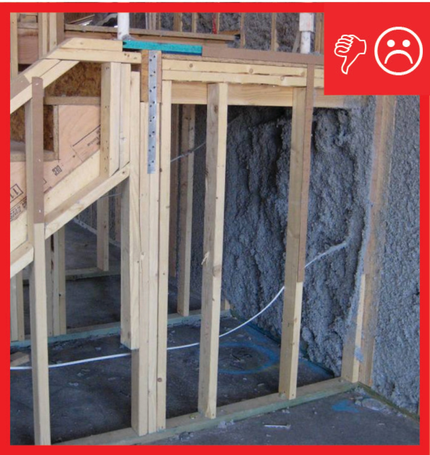
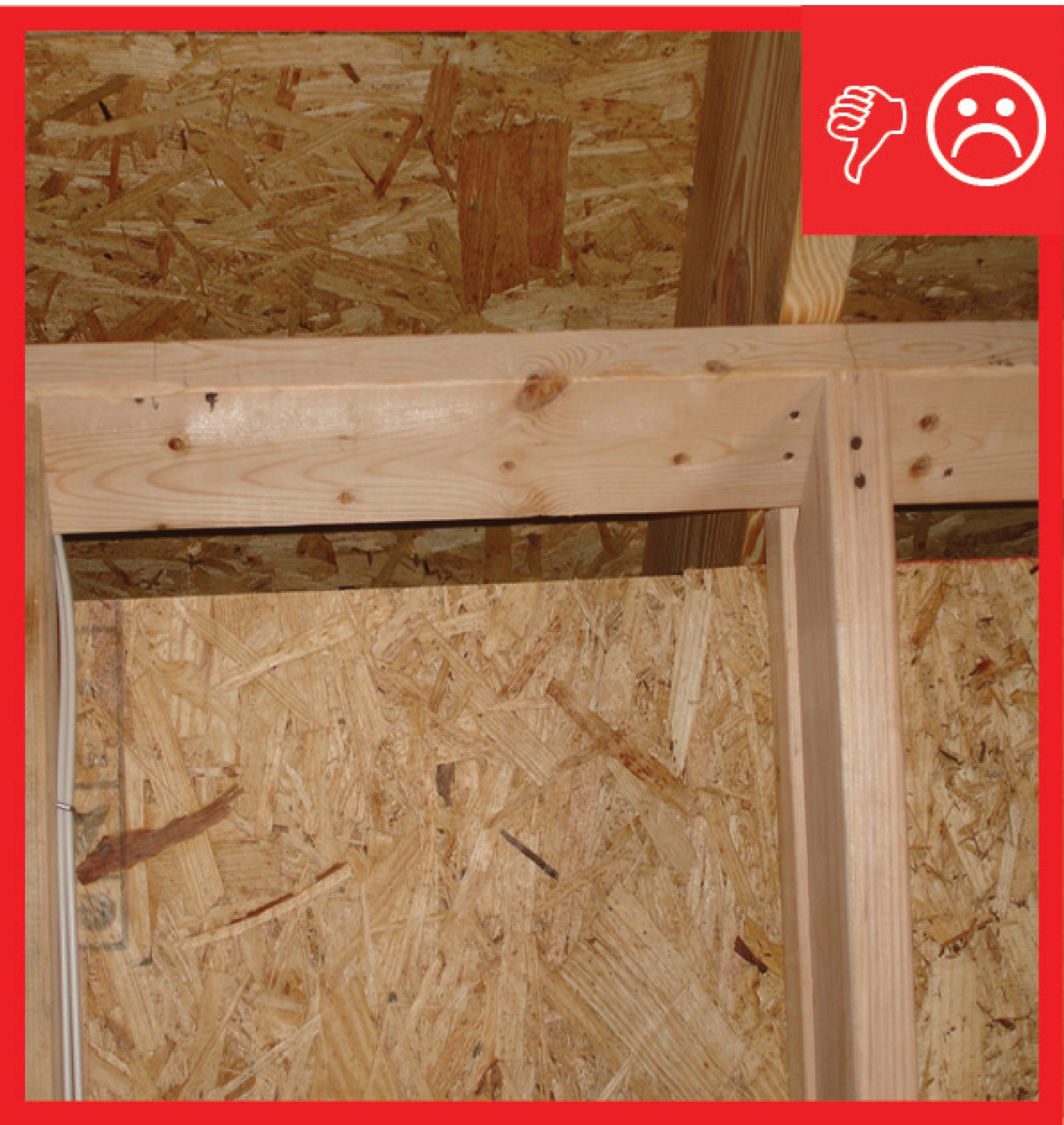
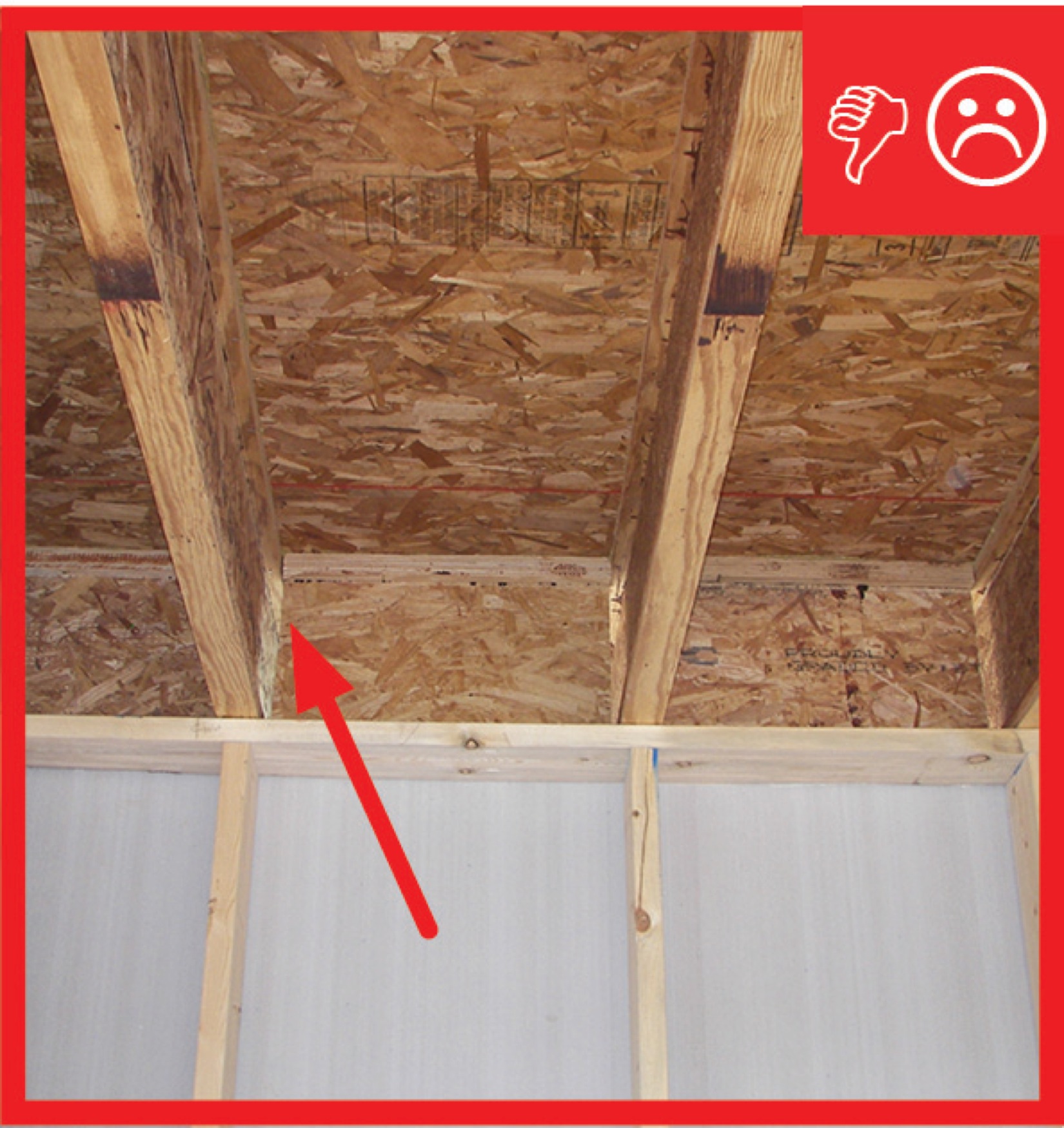
Wrong – An opportunity to use structural members as a natural air barrier was missed in this home and blocking was not initially planned for between the garage and living space.
Image
Image
Image
Image
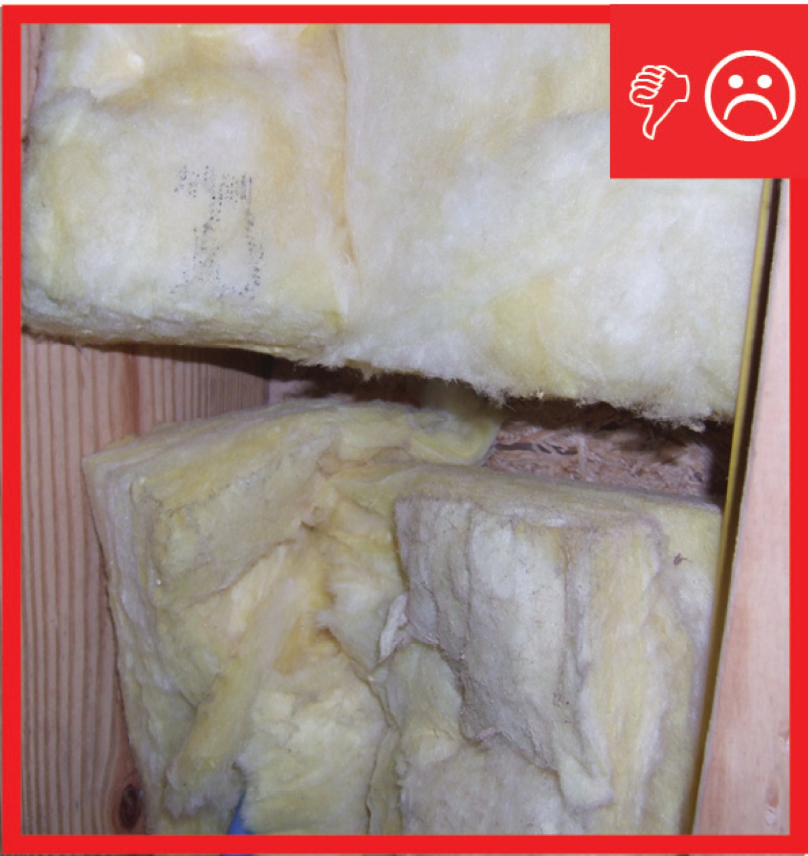
Wrong – Insulation does not fill entire cavity nor is there an air barrier present between the double wall
Image

Image
Image

Image

Image
Image