Showing results 1 - 199 of 199
Image
Image
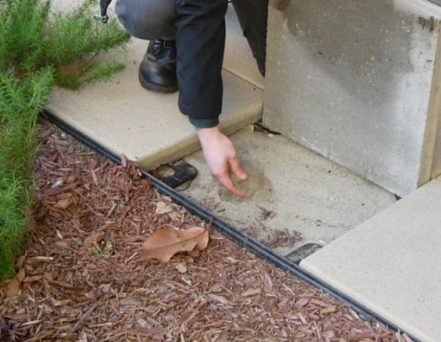
Impervious surfaces like patio slabs, sidewalks, and driveways that are within 10 feet of the home should slope away from the house.
Image

Image
A drywell, shown here used for downspout catchment, can also be used to receive water from a French drain.
Image
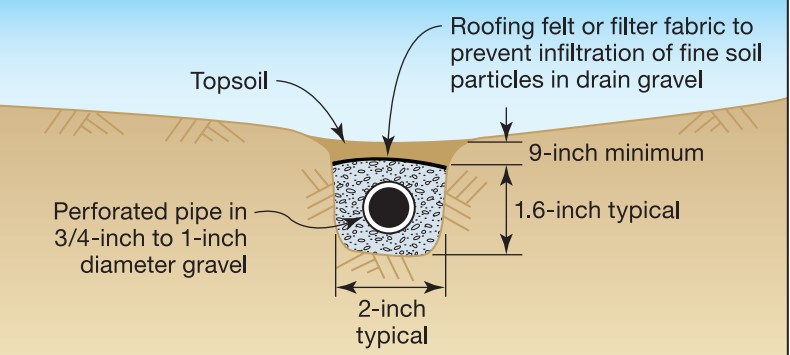
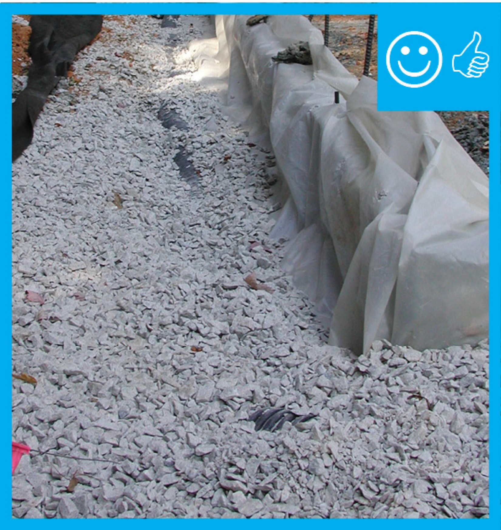
A French drain contains a perforated drain pipe wrapped in rock and landscape fabric.
Image
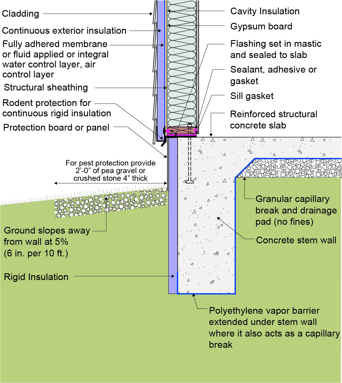
A layer of pea gravel or crushed stone, 4 inches thick and sloped 5%, provides a pest-resistant ground break around the perimeter of a slab foundation
Image
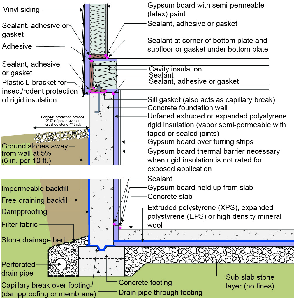
A layer of pea gravel or crushed stone, 4 inches thick and sloped 5%, provides a pest-resistant ground break around the perimeter of a basement foundation
Image
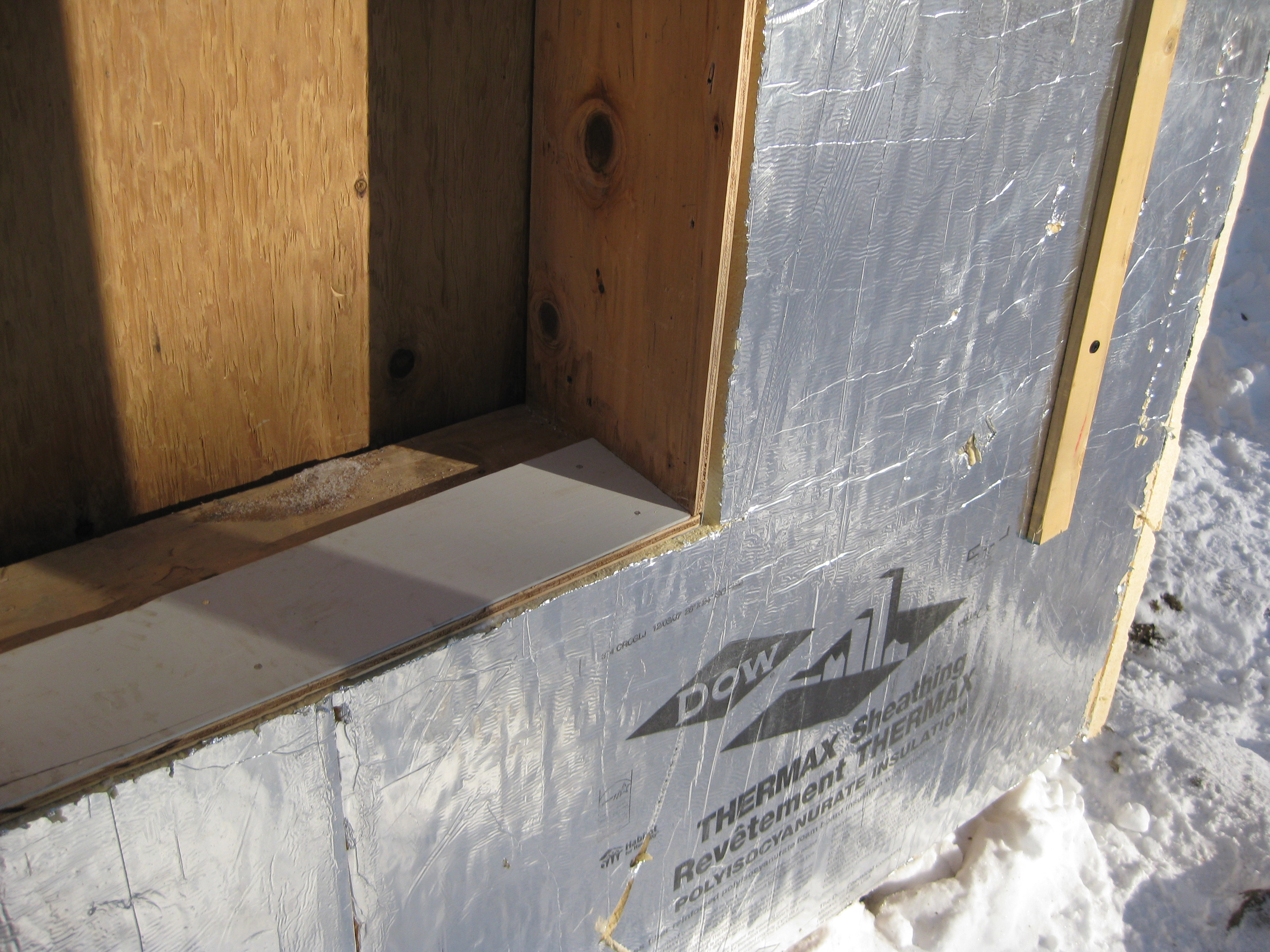
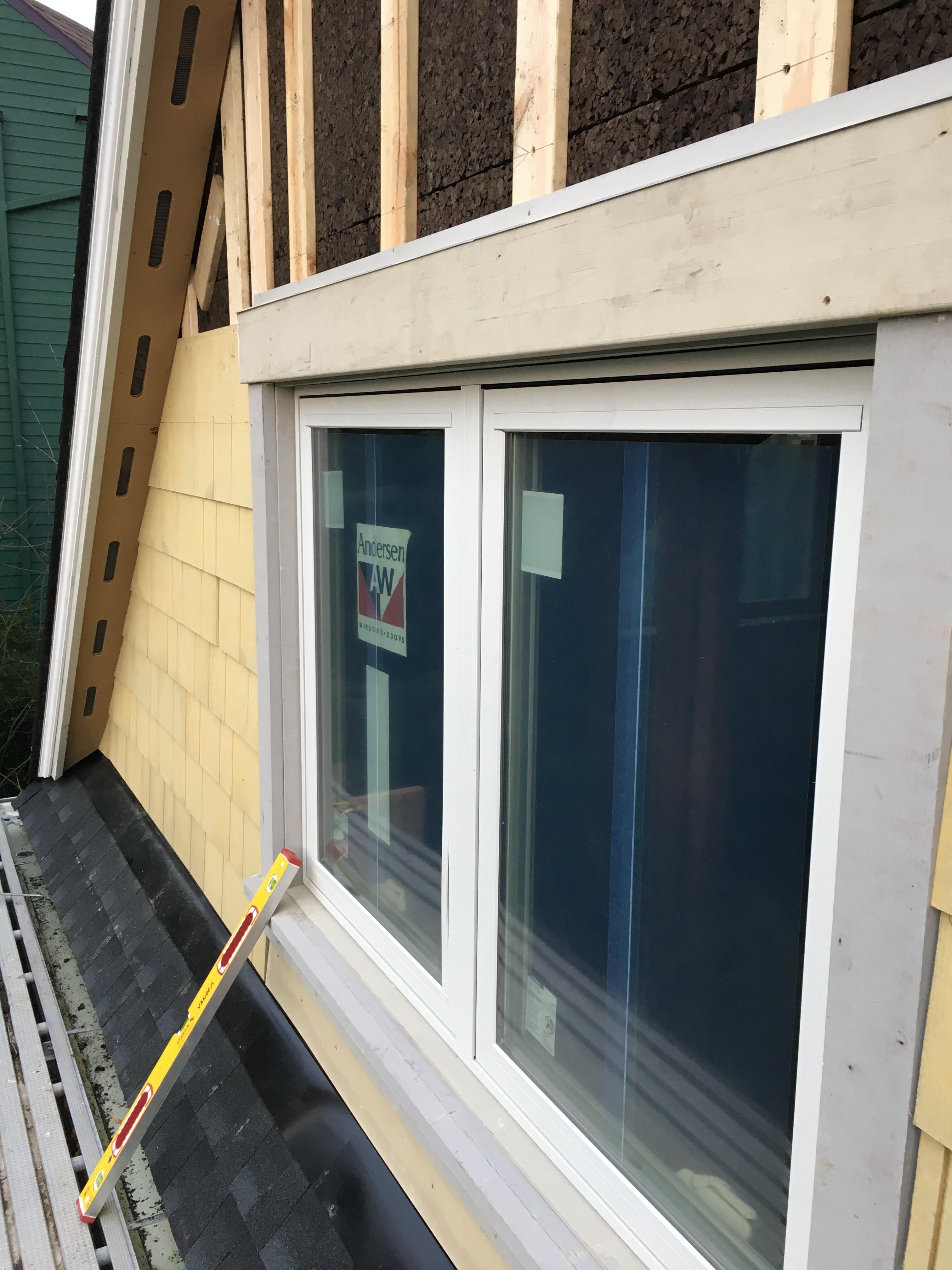
A piece of siding is used as sill extension and to provide slope in the opening for the window, which is deeper because exterior rigid foam has been added
Image
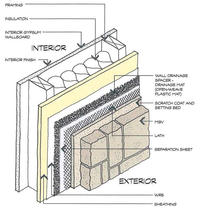
A plastic fiber drainage mat rainscreen provides uniform support for the siding and allows moisture to flow horizontally and diagonally in addition to vertically.
Image
Image
Image
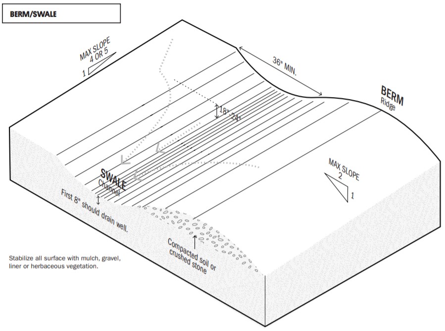
A swale and berm can be installed together across a slope to slow the downhill flow of water.
Image

Adding planted terraces to a sloped yard can slow down runoff and reduce erosion
Image
Image
Image
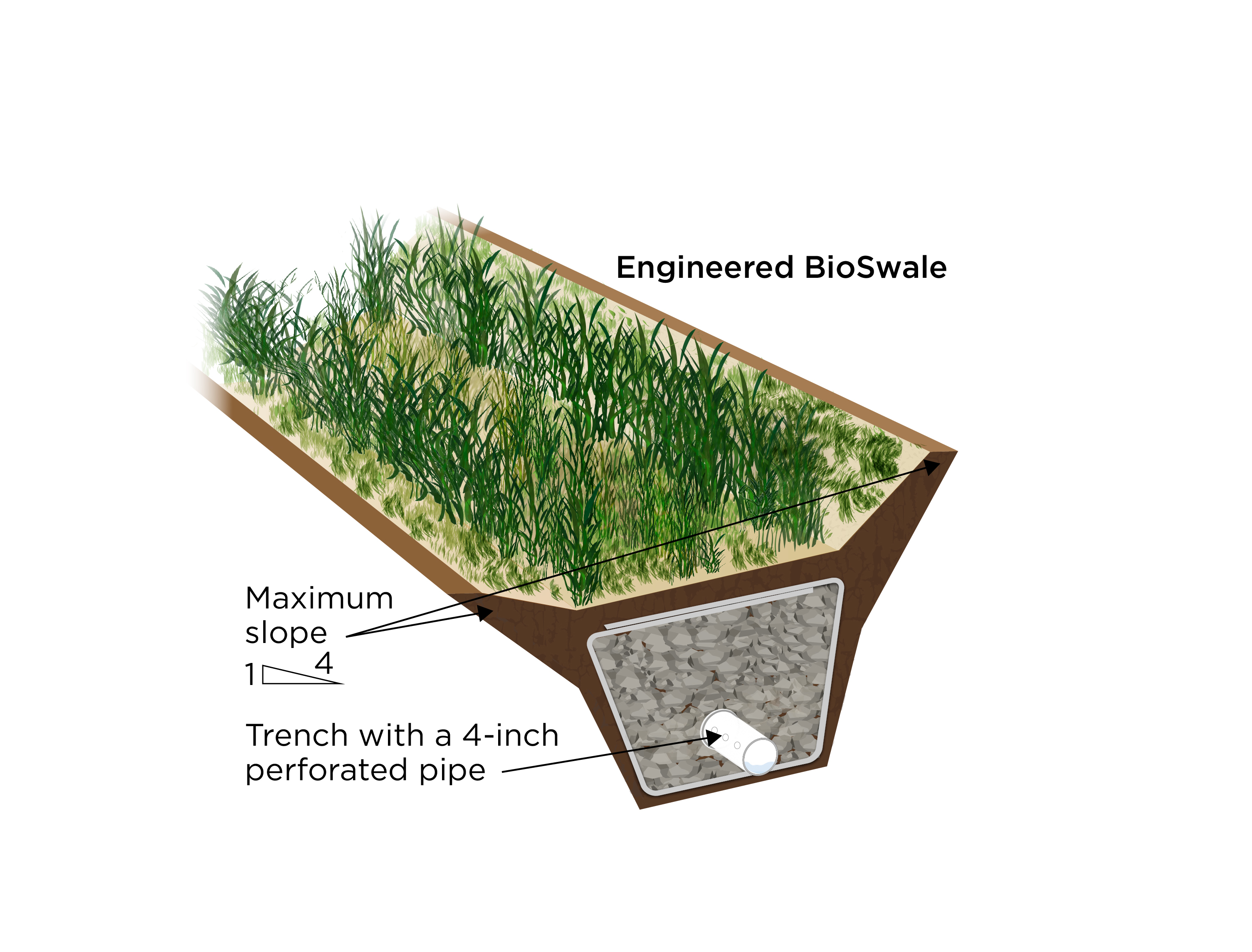
An engineered bioswale uses perforated pipe laid in rock and landscape fabric at the bottom of a vegetated trench to direct water away from a site.
Image

Image
Image
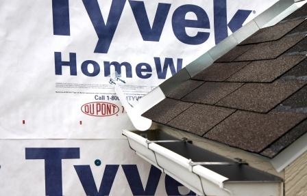
Apply self-adhesive flashing over top edge of the wall flashing, diverter, and housewrap
Image
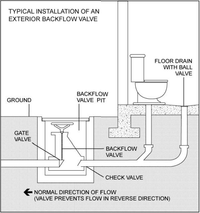
Backflow prevention devices keep water and sewage from entering the home during a flood preventing damage and health and safety issues.
Image
Berms are compacted earth or gravel ridges that slow the flow of water from rain, riverine flooding, or storm surges in coastal areas.
Image
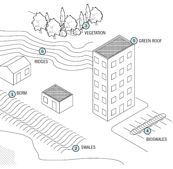
Berms, swales, bioswales, ridges, and vegetation all help to control rainwater runoff on residential sites.
Image

Bioswales or rain gardens filter storm water through vegetation and rock and sand substrate layers.
Image
Image
Clean taping areas and install 3" tape on vertical joint of upper insulation overlapping the horizontal joint
Image
Image

Comprehensive above-grade water management details for a crawlspace foundation include a capillary break over the crawlspace floor, slope the surface grade away, installing gutters that slope away, and capillary break under sill plate.
Image
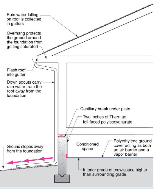
Comprehensive water management features include a capillary break (≥ 6-mil polyethylene sheeting) at all crawlspace floors
Image
Concrete (4 inches thick at 5% slope) provides a pest-resistant perimeter around the foundation
Image
Concrete pavers set in 4 inches of sand provide a pest-resistant ground break at the building perimeter.
Image
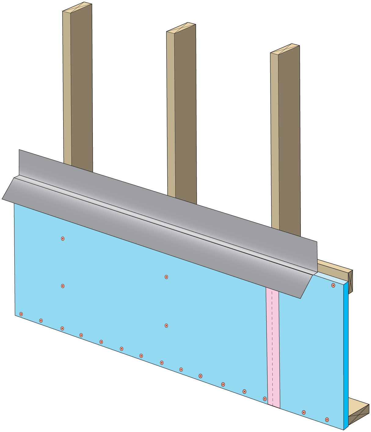
Continuous L-metal flashing integrated with underlayment at roof-wall intersections
Image

Image
Image
Image
Image
Image
Duct/pipe penetration with metal cap flashing and wood blocking for trim attachment
Image
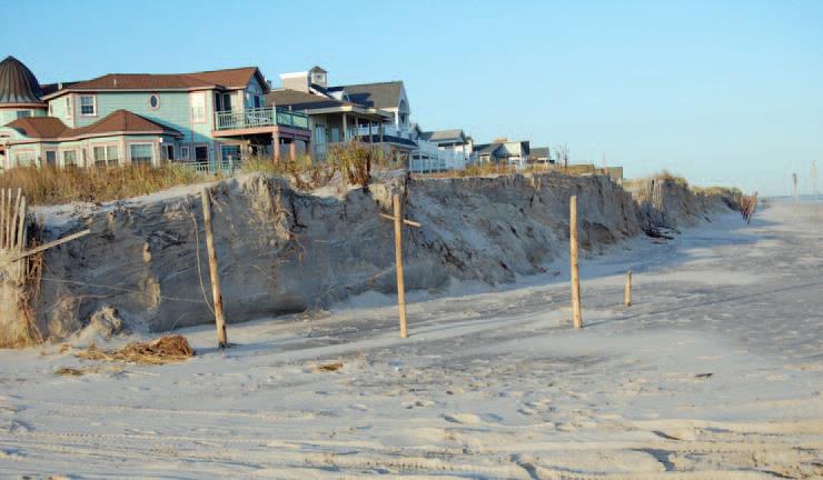
Dune erosion caused by the combination of a hurricane and a nor’easter in Ocean City, New Jersey
Image
Image
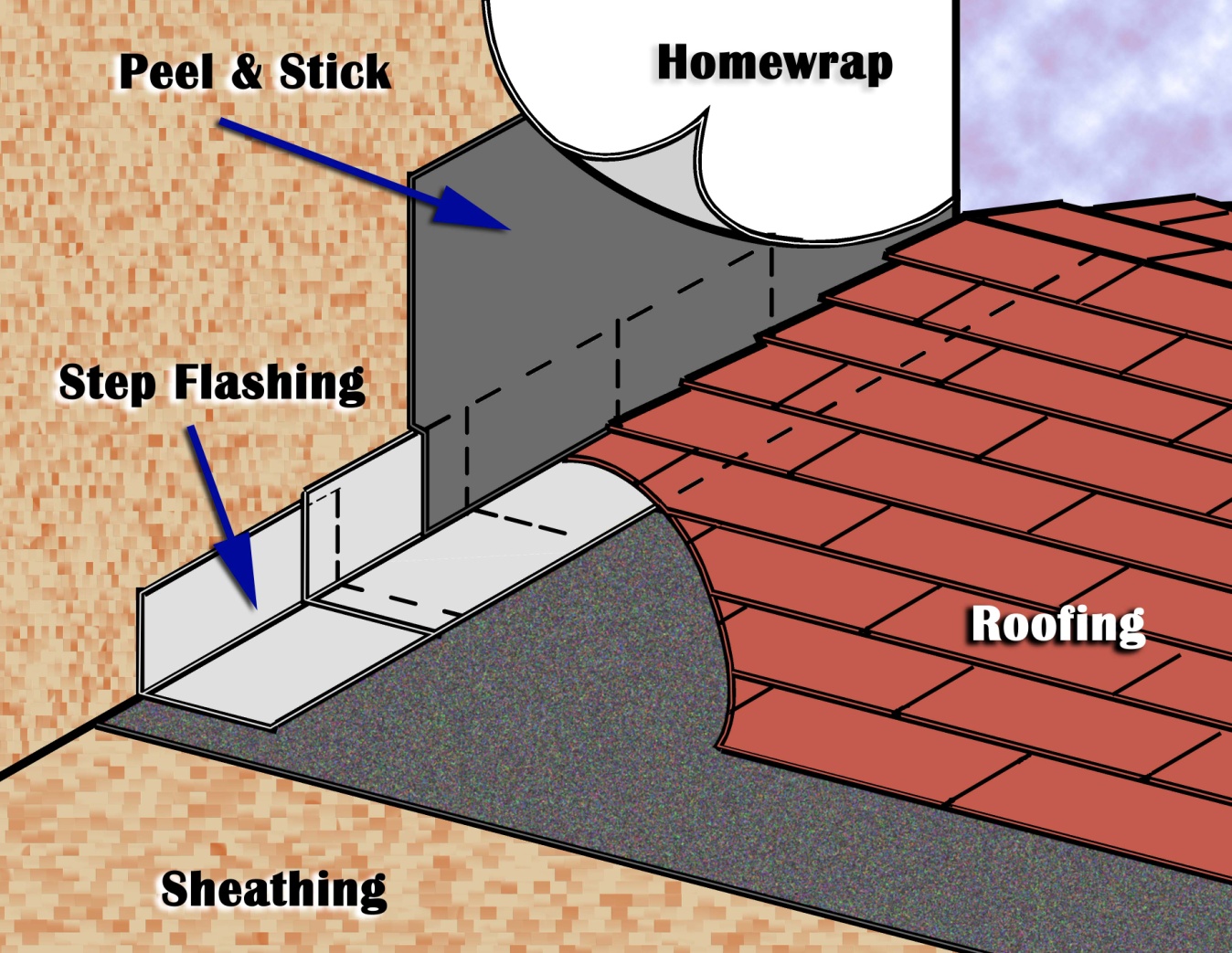
Existing wall-to-lower roof transition retrofitted with a new strip of fully adhered air control transition membrane, new step flashing, new roof underlayment, and new cladding
Image
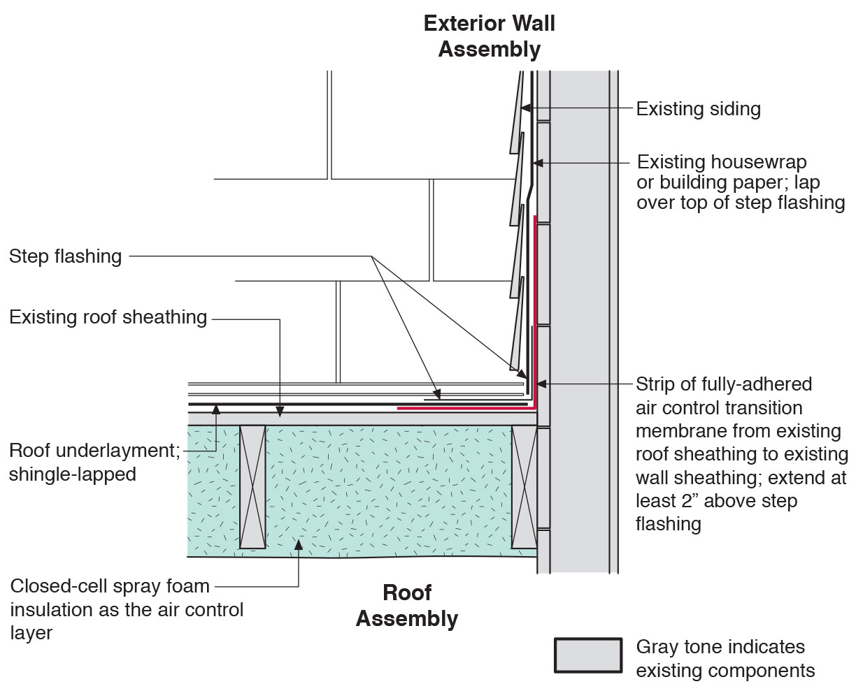
Existing wall-to-lower roof transition with a new strip of fully adhered air control transition membrane, new step flashing, new roof underlayment, and new cladding – view from eave
Image
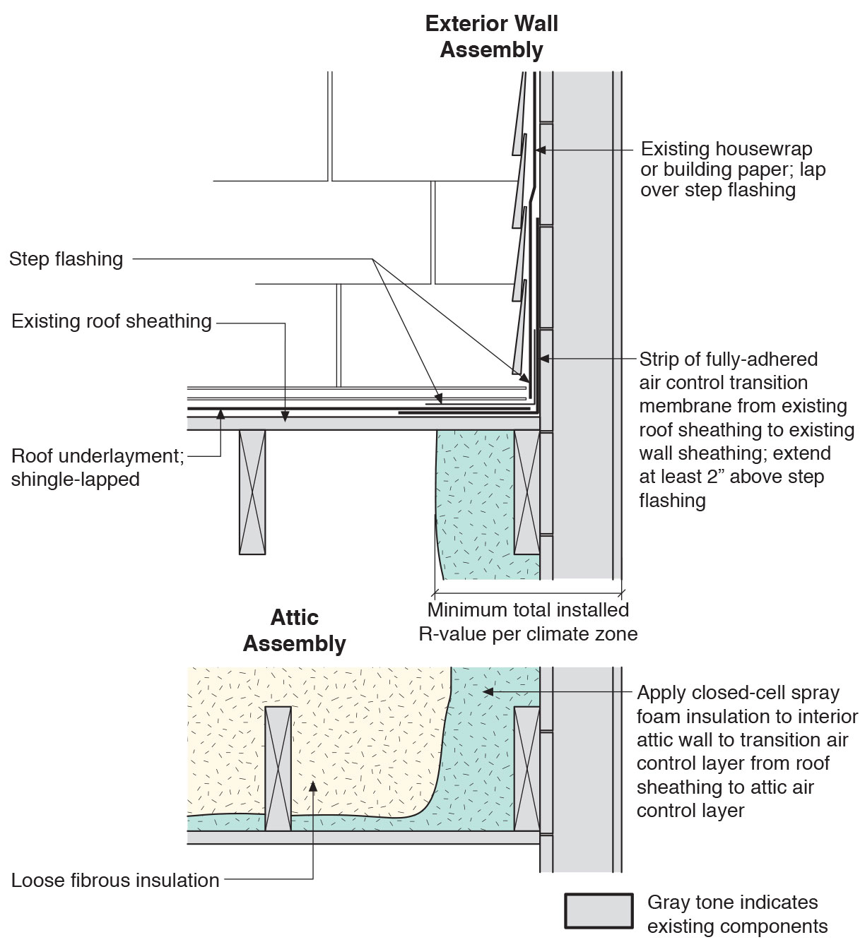
Existing wall-to-lower roof with attic transition with a new strip of fully adhered air control transition membrane, new step flashing, new roof underlayment, and new cladding – view from eave
Image
Image
Image
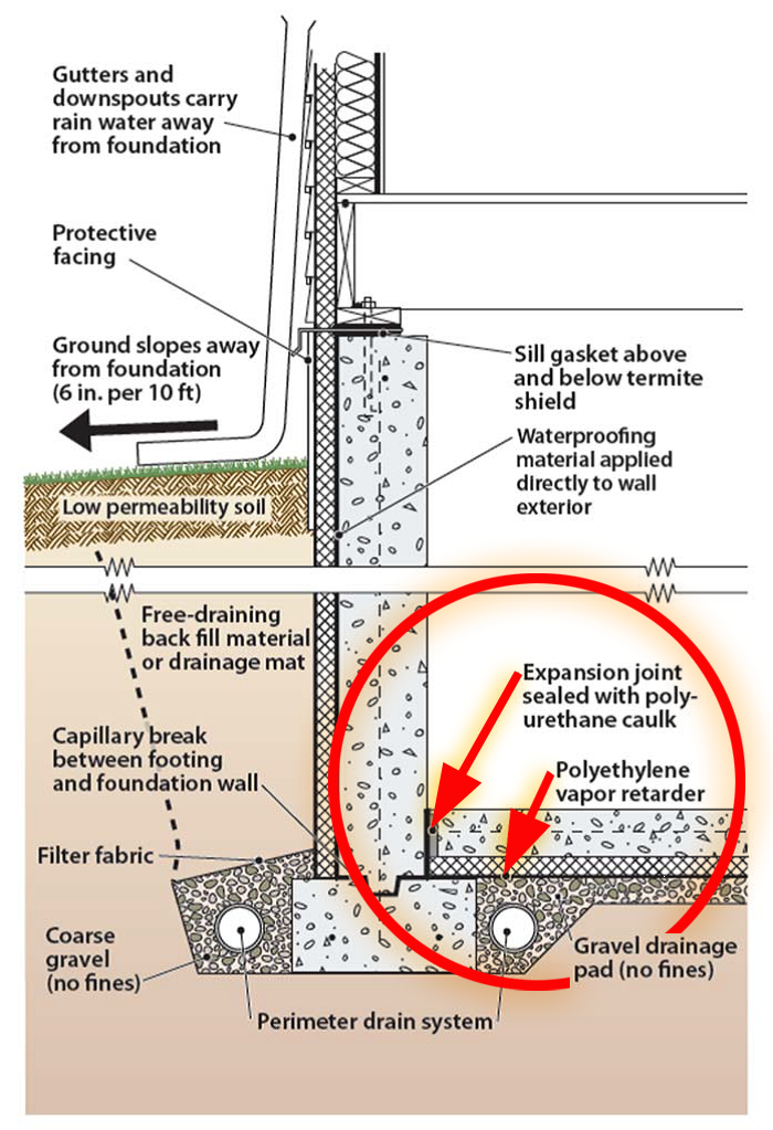
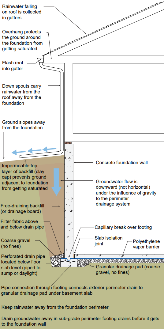
Good water management practices like sloping grade away from house, and installing gutters, perimeter drain pipe, a capillary break, and free-draining soils or drainage mat protect the foundation from water saturation.
Image
Image
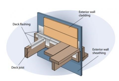
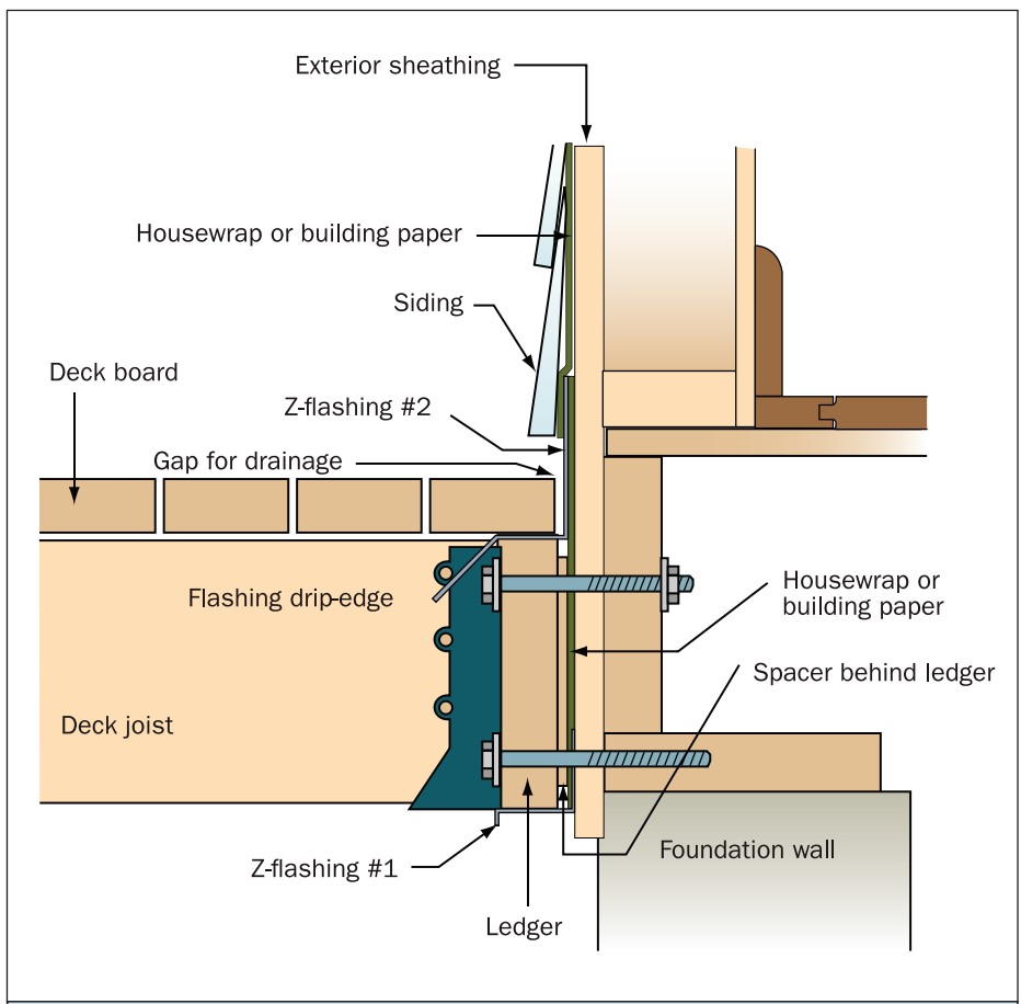
Heavy metal flashing protects the deck timbers and separates them from the wall at the wall-deck connection which is vulnerable to both ember entrapment and water damage.
Image
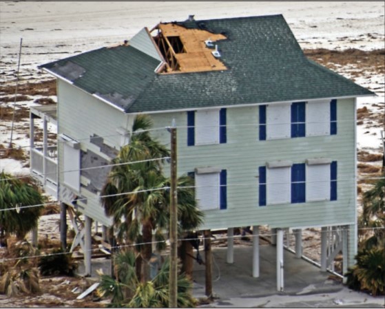
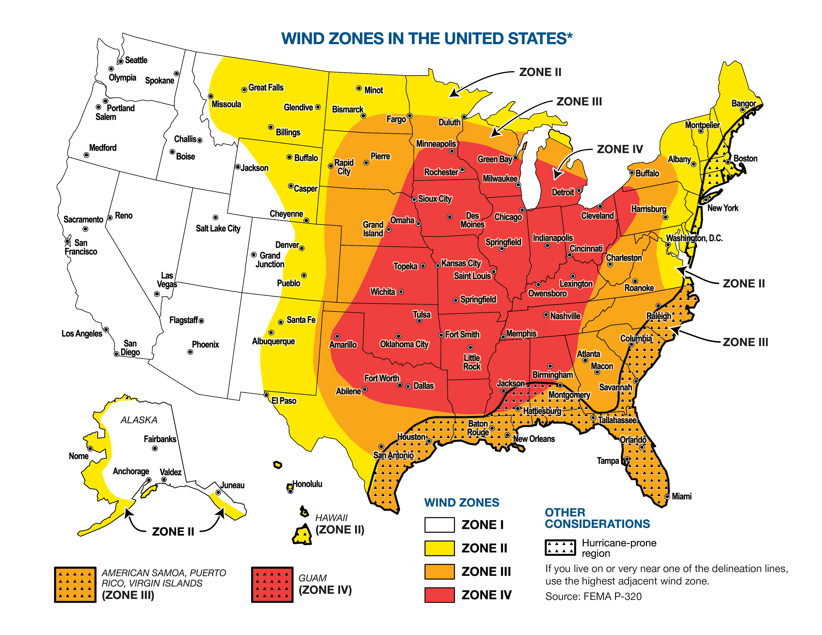
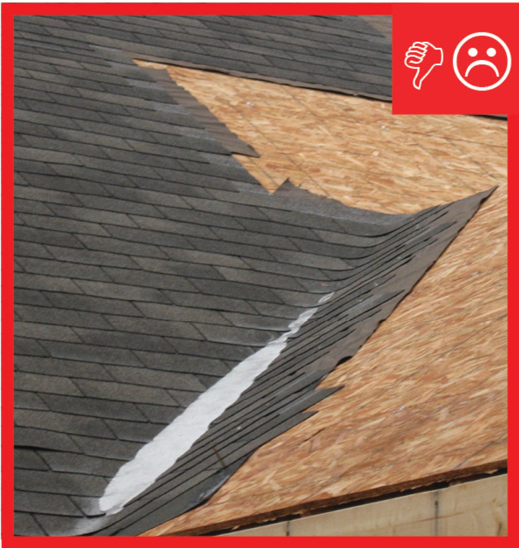
High winds pulled the asphalt shingles and sheathing panels off this coastal home, although storm shutters protected the windows
Image

House wrap is sealed at all seams and overlaps flashing to serve as a continuous drainage plane over the exterior walls.
Image
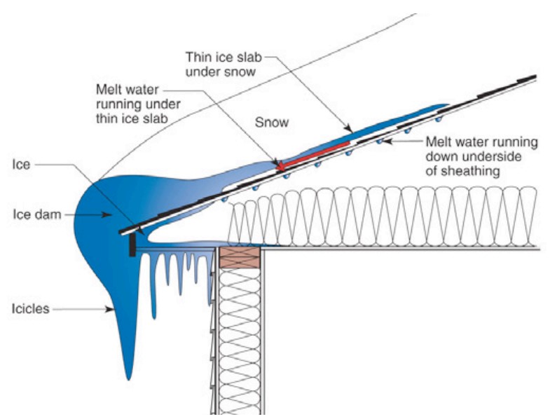
Ice dams form when warmth from the attic causes roof snow to melt and flow to roof eaves where it refreezes at the colder overhang and forms a buildup of ice causing more snowmelt to puddle where it can wick back through shingles and leak into the attic
Image
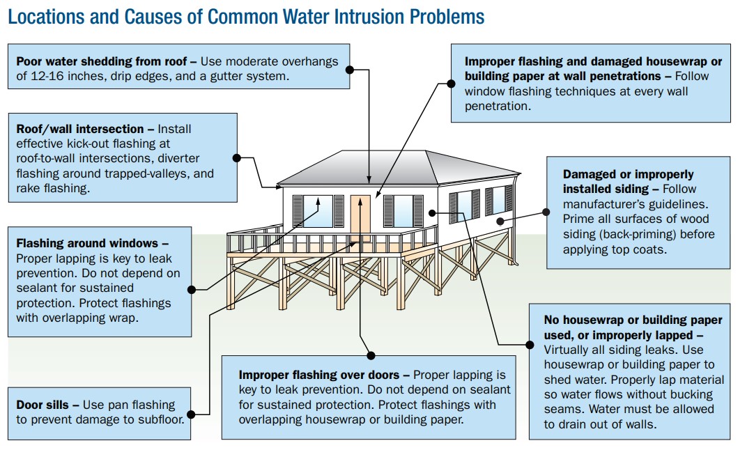
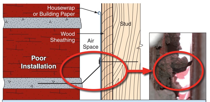
Improper flashing can allow rain water into walls, causing significant damage
Image
Image
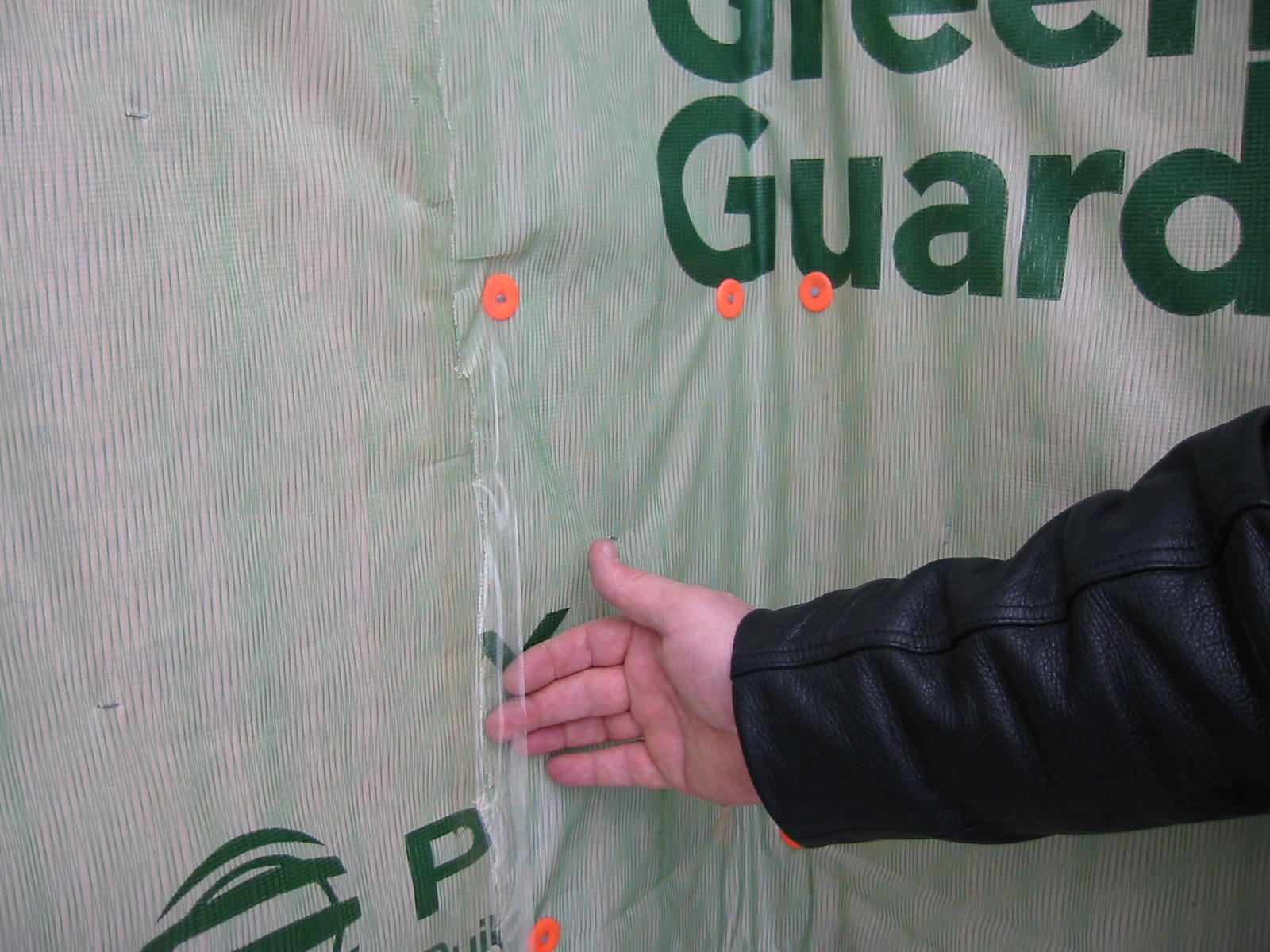
Install all layers of the drainage plane to overlap, not underlap, to direct bulk water down and out of the wall.
Image
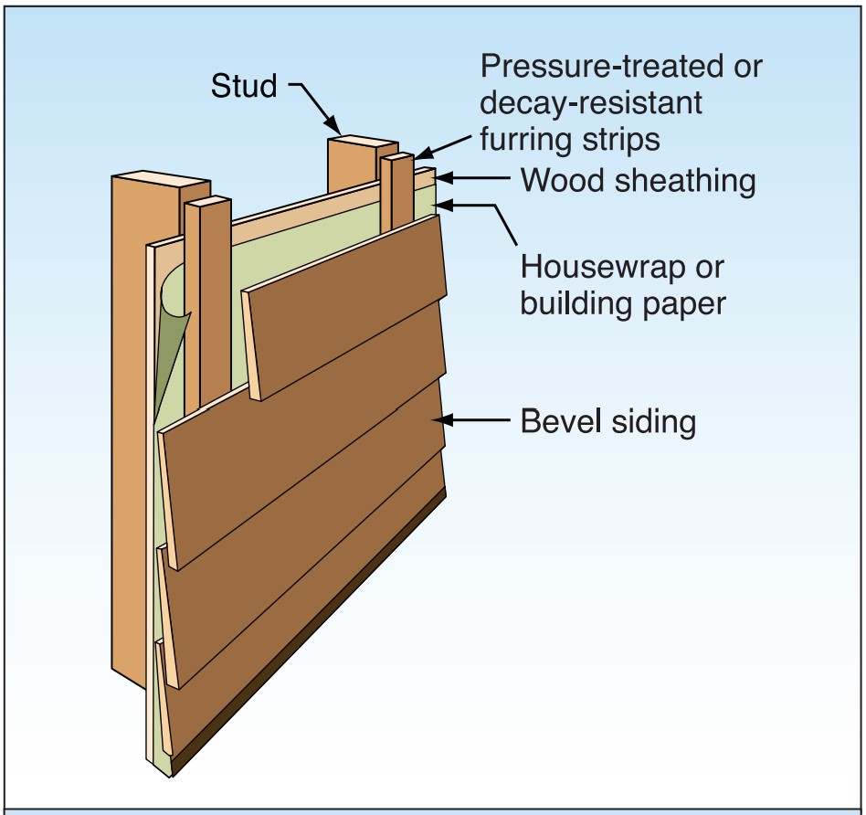
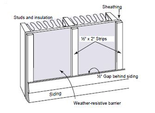
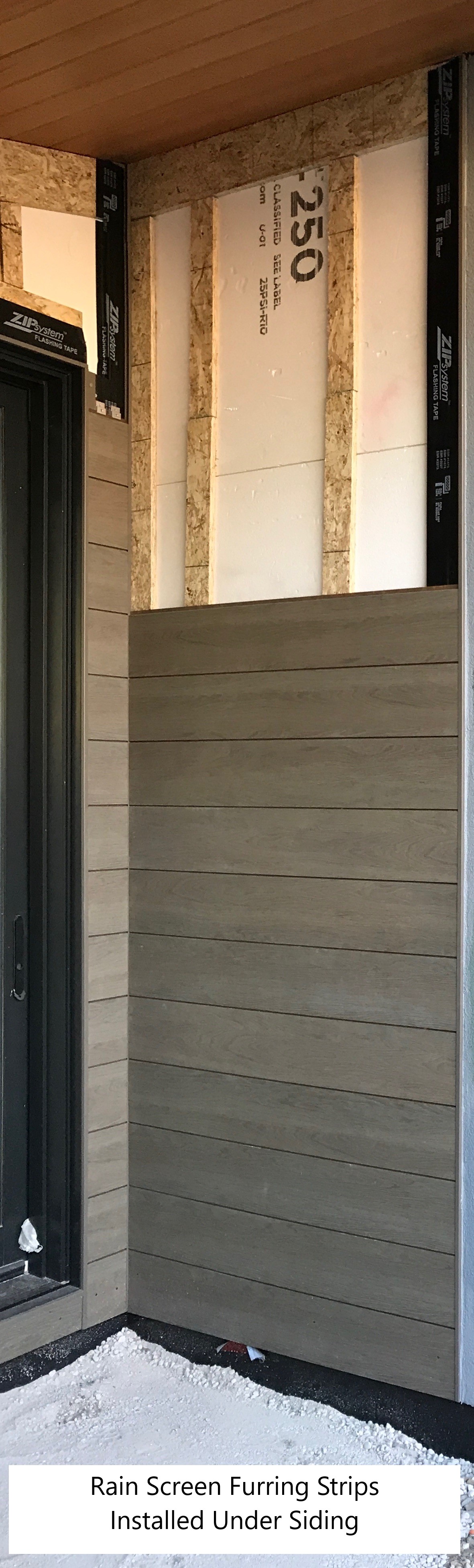
Install furring strips over house wrap to provide a rainscreen behind wood siding.
Image
Image
Image
Image
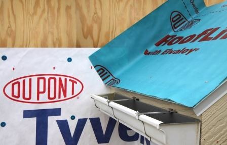
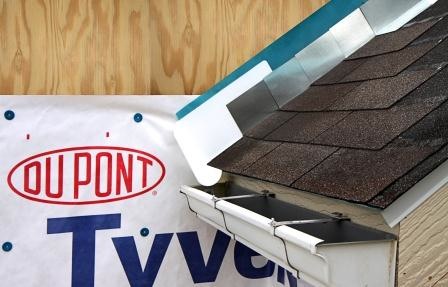
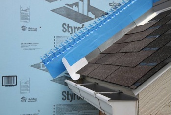
Install shingle starter strip then kick-out diverter; attach to roof deck but not sidewall
Image
Image

Image
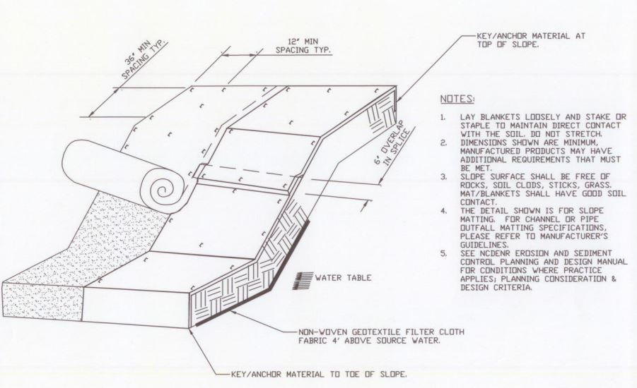
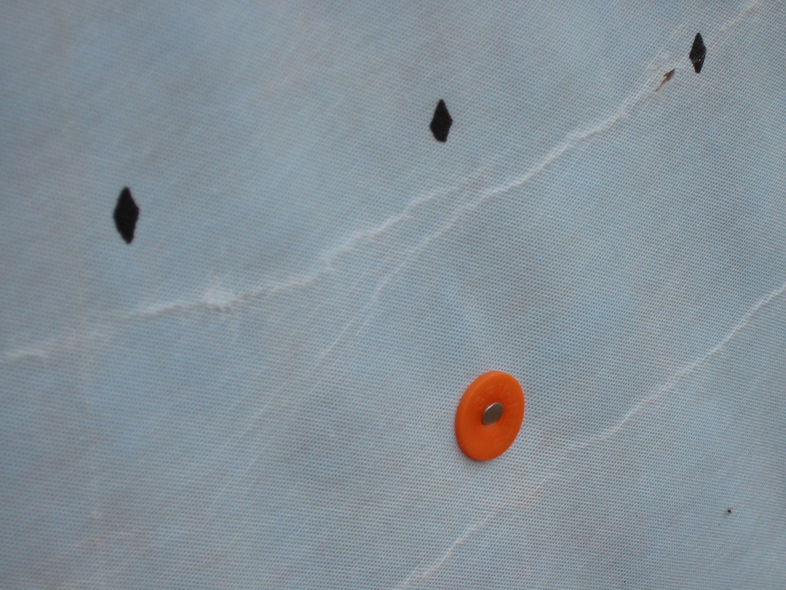
Installation of an erosion control blanket to minimize soil loss on sloped ground that has no established vegetation
Image

Image
Image
Image
Image

Image
Image
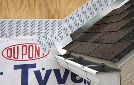
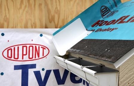
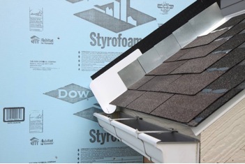
Place first shingle and next section of sidewall flashing over upper edge of diverter
Image
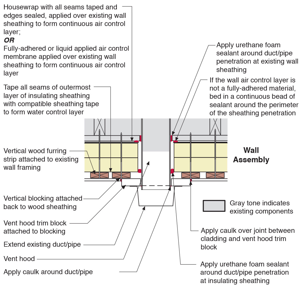
Plan view of duct or pipe penetration through exterior wall showing flashing and air sealing details
Image
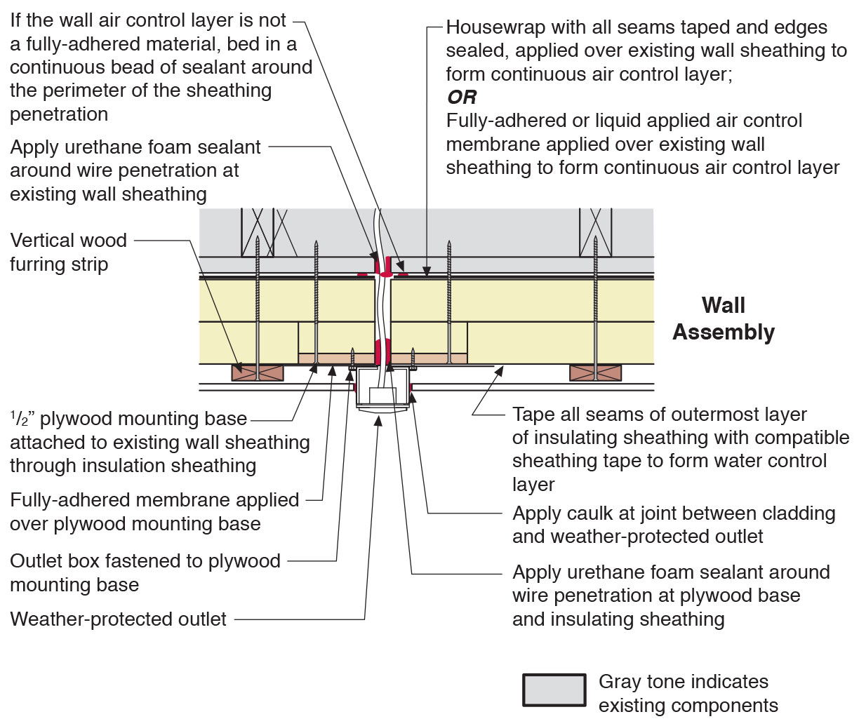
Plan view of electric box installation in exterior wall showing flashing and air sealing details
Image
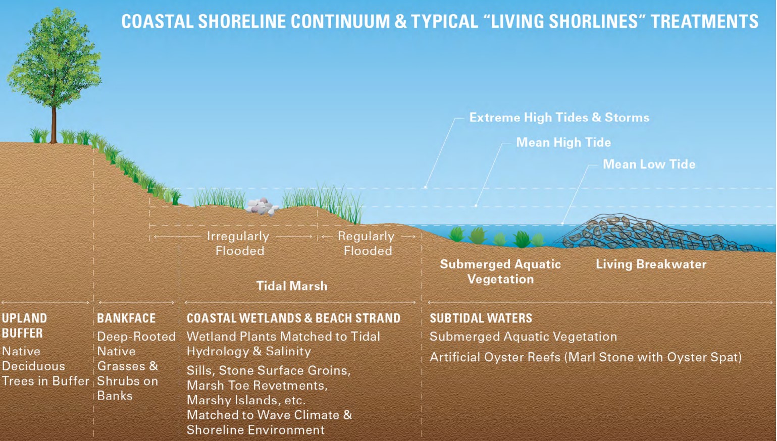
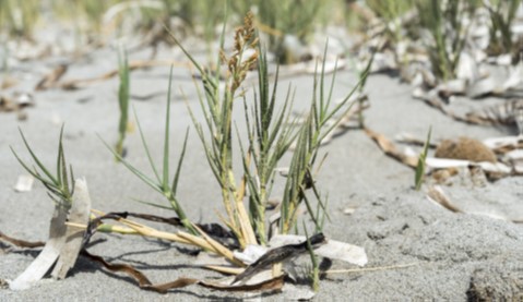
Planting deep-rooted native grasses and shrubs on the banks of shorelines can help reduce the effects of erosion on sandy slopes
Image
Image
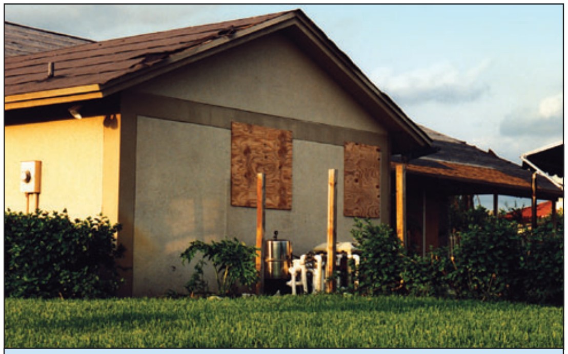
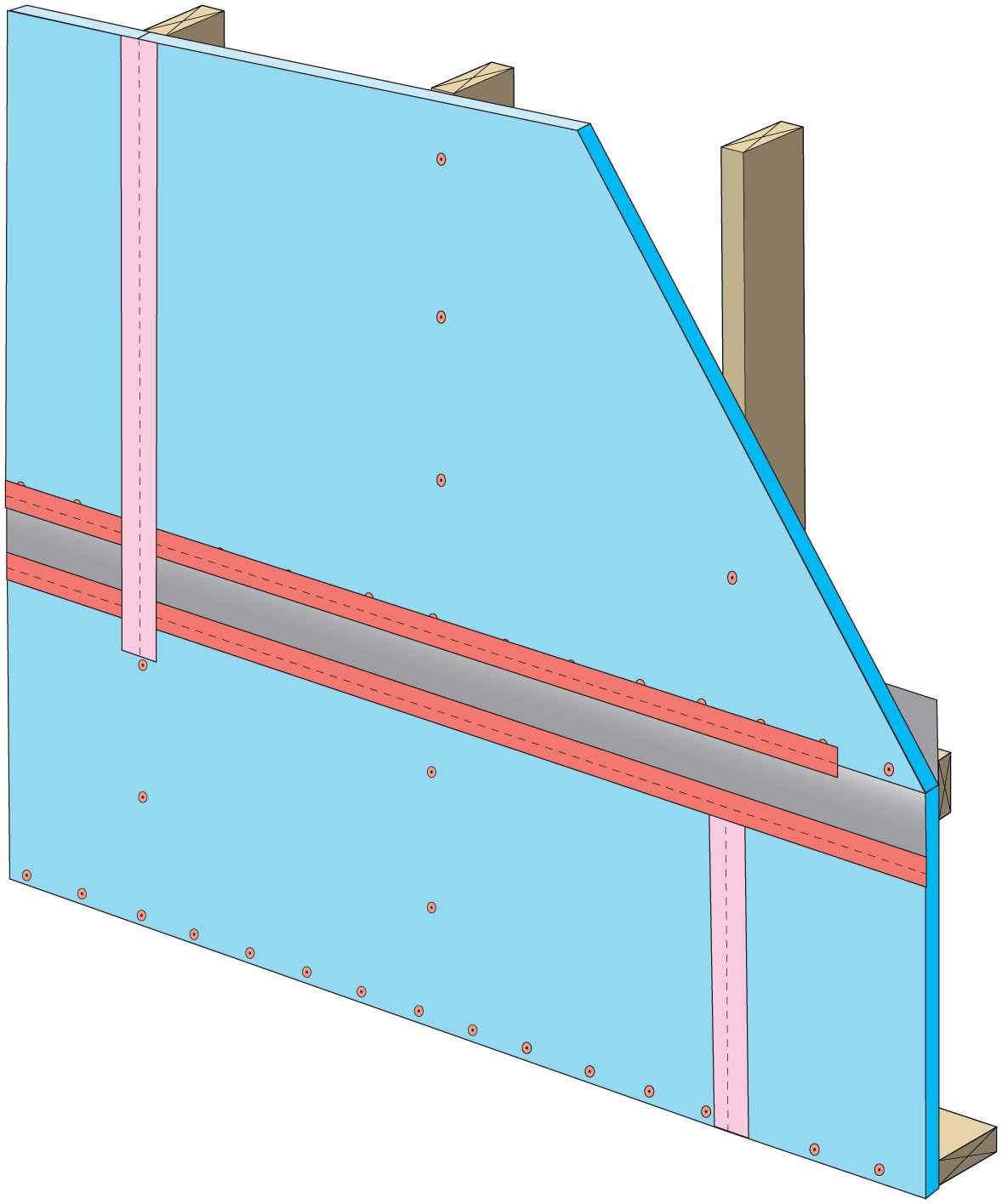
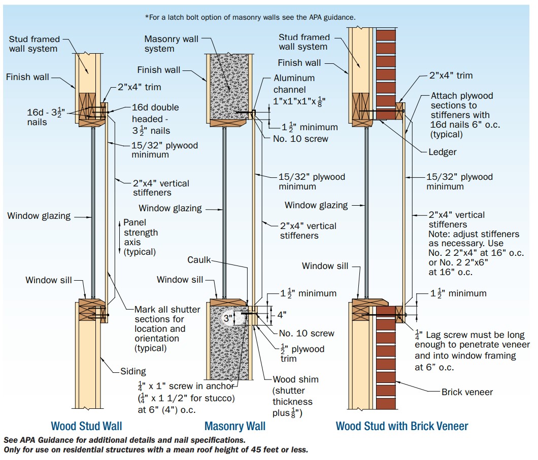
Plywood or OSB panels are a cost-effective way to protect windows from wind-borne debris.
Image
Image
Porous surfaces like pavers allow water to pass through and percolate slowly into the soil
Image
Image
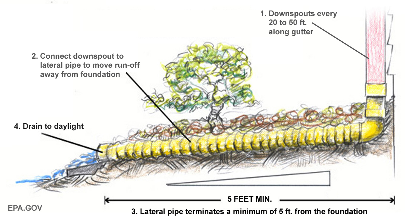
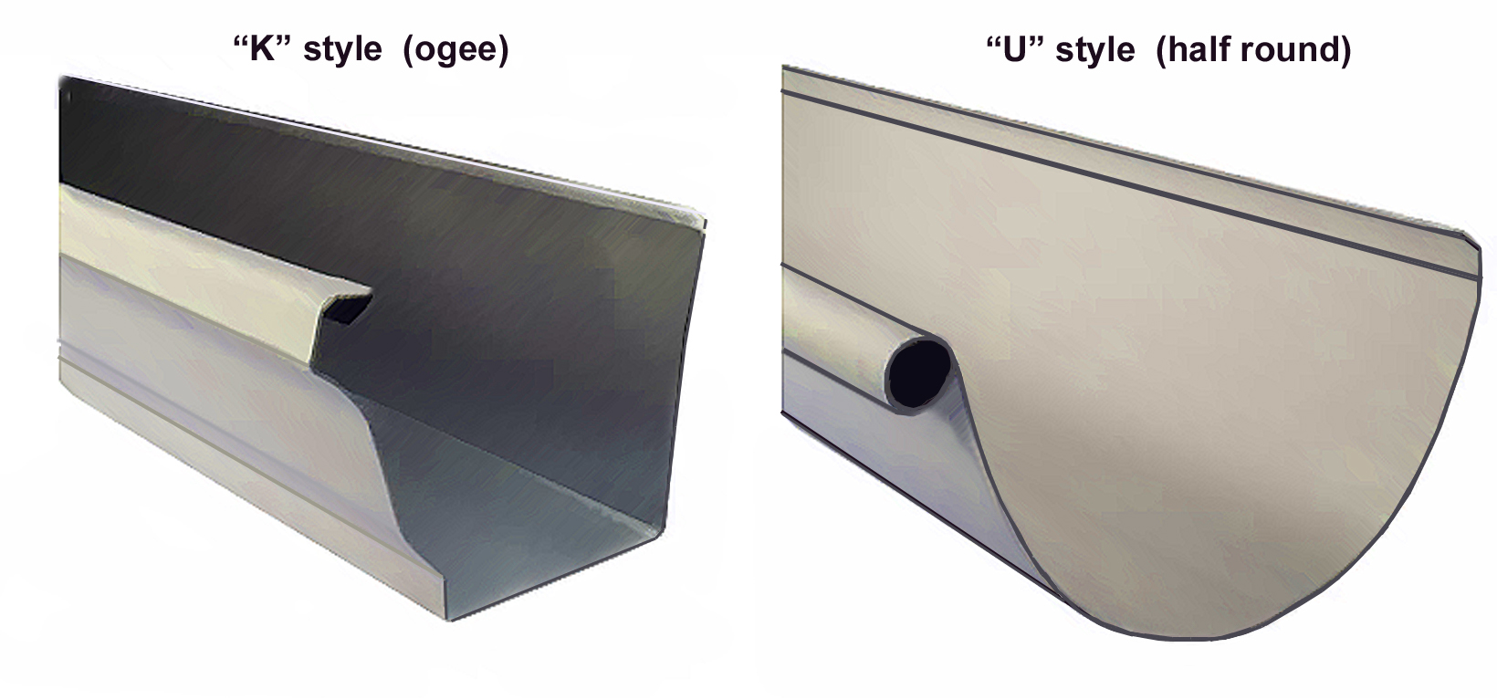
Proper gutter and downspout system terminates with final grade sloping away from the home
Image
Provide flashing and sealing integrated with the air and water control layers for vents and other roof penetrations
Image

Repair leaks and cracks, and cover holes in foundation floors and walls to minimize water and vapor entry.
Image
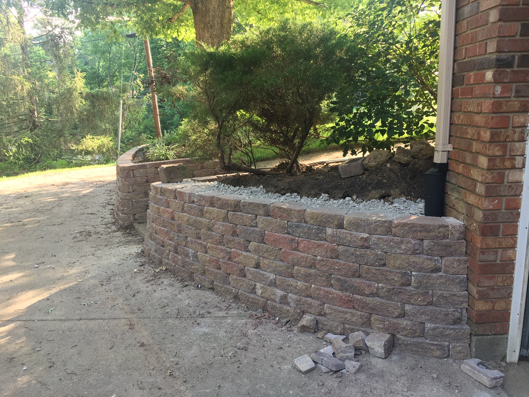
Retaining walls can prevent erosion and landslides and maintain access to critical infrastructure
Image
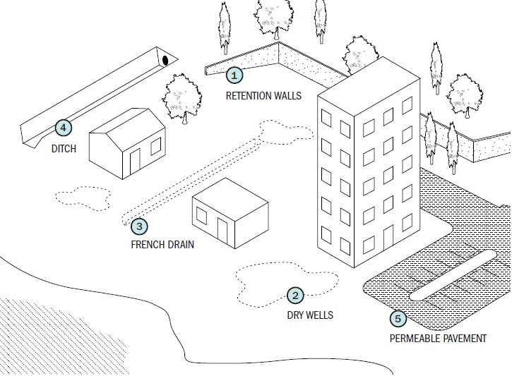
Retention walls, permeable pavement, french drains, drywells, and ditches all help to divert, collect, and manage the flow of stormwater on a site.
Image
Ridges can be constructed and planted to slow the downward flow of water and stabilize slopes.
Image
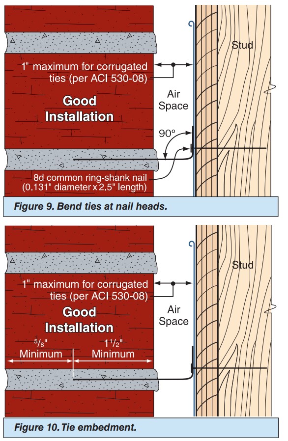
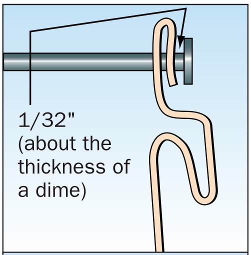
Right – The ties are bent at a 90 degree angle at the nail head and embedded into the mortar joint at least 1.5 inches.
Image
Right – The ties are bent at a 90 degree angle at the nail head and embedded into the mortar joint at least 1.5 inches.
Image
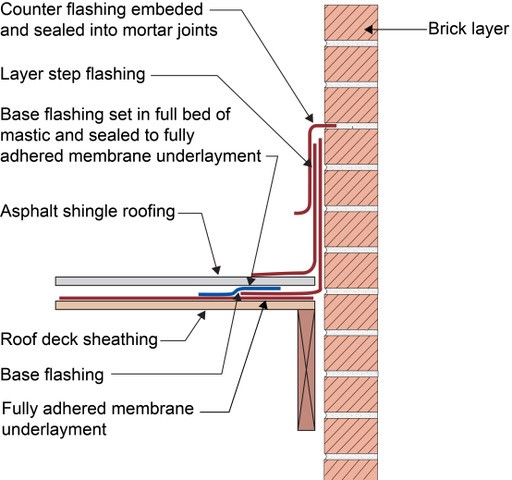
Right - Counterflashing tops a layer of step flashing which comes down above the asphalt shingle and a layer of L-shaped base flashing which comes down and extends below the shingle; the base flashing is adhered to the roof underlayment with mastic, shown
Image
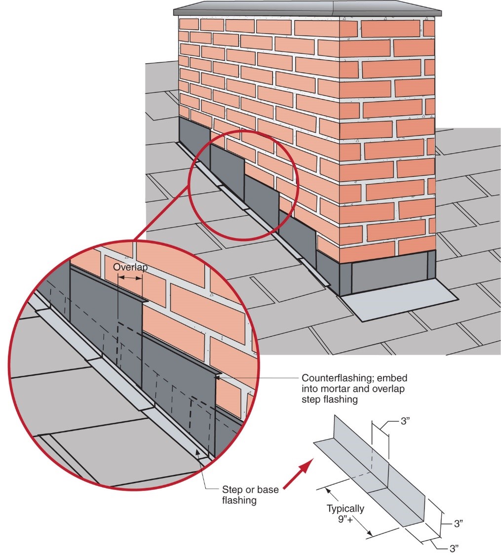
Right - Step flashing along a chimney is integrated in a layered manner with asphalt shingle roofing and topped with counterflashing that is embedded into brick mortar joint above
Image
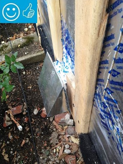
Right - The pipe penetration is properly flashed and furring strips are installed on each side in preparation for installing cladding
Image
Image
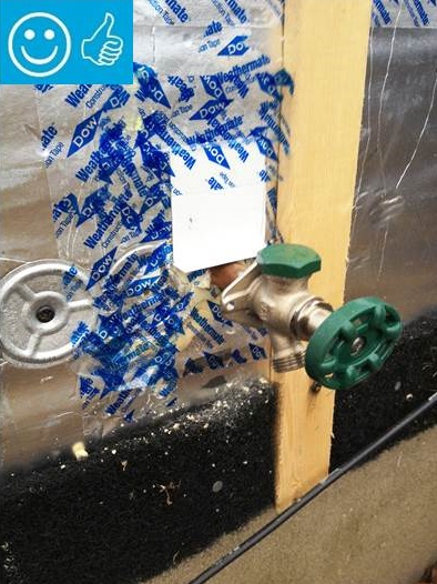
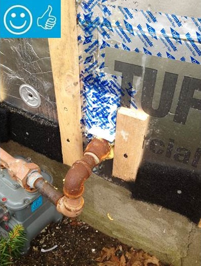
Right - The water and air control layers are properly integrated around the hose bib
Image
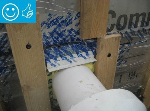
Right - This duct penetration is properly flashed and integrated with the taped, foil-faced foam sheathing layer, which serves as the air and water barrier
Image
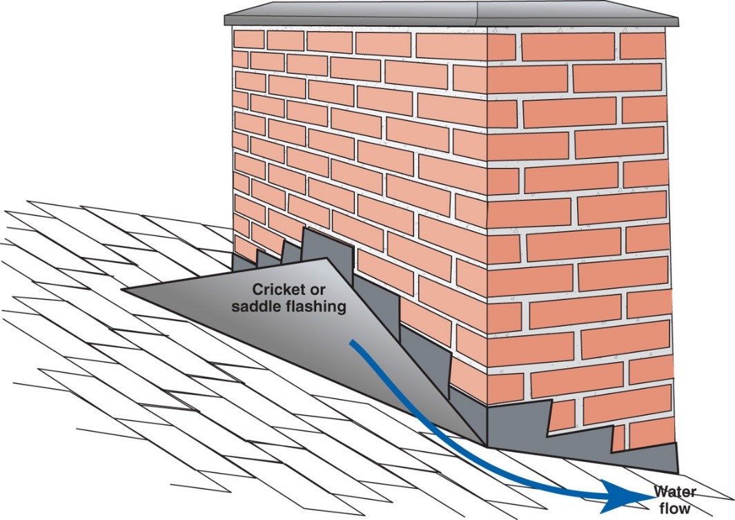
Right – A chimney cricket is installed and flashed to direct rainwater around the chimney
Image
Image

Image
Right – Furring strips provide a drainage and ventilation gap between the siding and the cork insulation.
Image
Right – Furring strips provide a drainage gap between the rigid foam and the siding.
Image
Right – House without gutters has waterproof liner, drain tile, and gravel bed extending more than 5 feet from foundation
Image
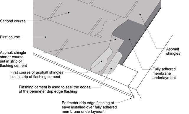
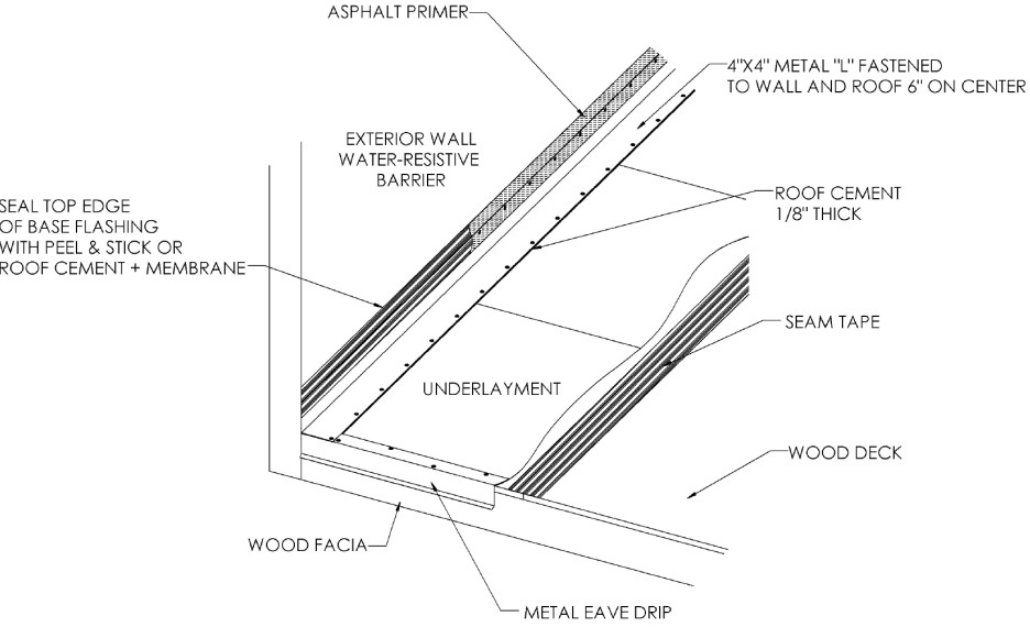
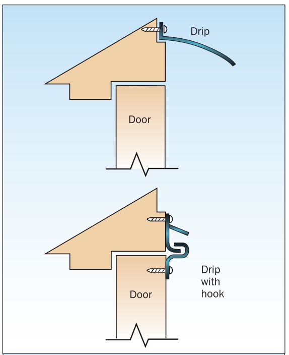
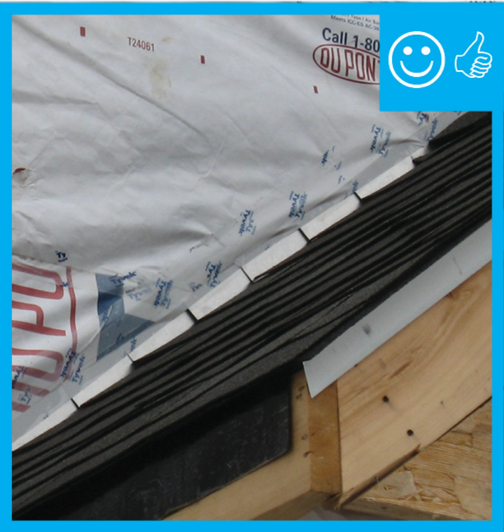
Right – If drip edge flashing is installed over fully adhered roof membrane at eaves, use flashing cement to seal the upper edge of the flashing
Image
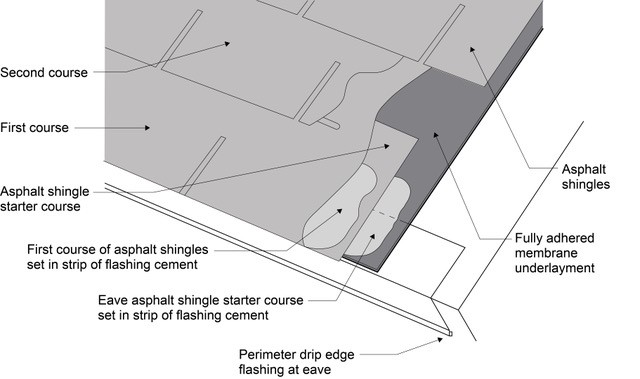
Right – Install asphalt shingles over a starter strip set in an 8-inch strip of flashing cement
Image
Image
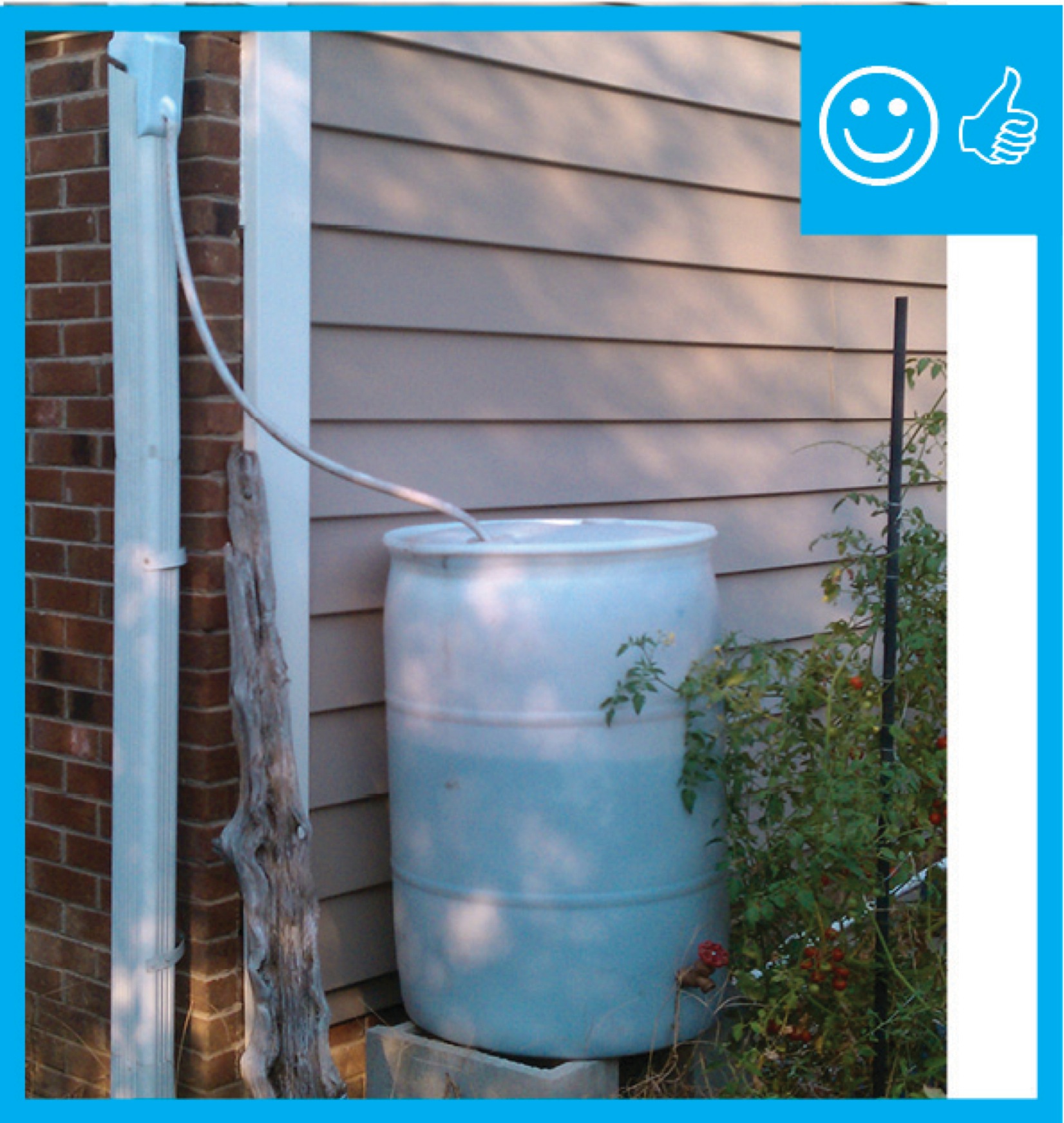
Right – Rain barrel installed with an overflow spout terminating at least 5 feet from foundation
Image
Right – Ripped OSB provides furring strips for a ventilation gap behind the wood siding.
Image
Image
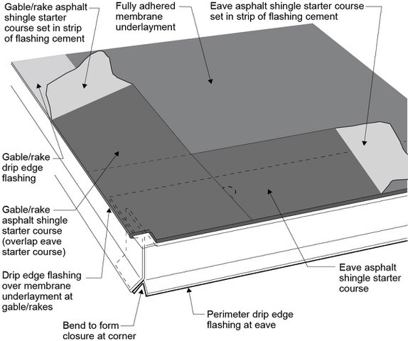
Right – Start asphalt shingle installation with a starter strip set in an 8-inch strip of flashing cement
Image
Right – The building felt is installed on all exterior walls and provides a complete drainage system
Image
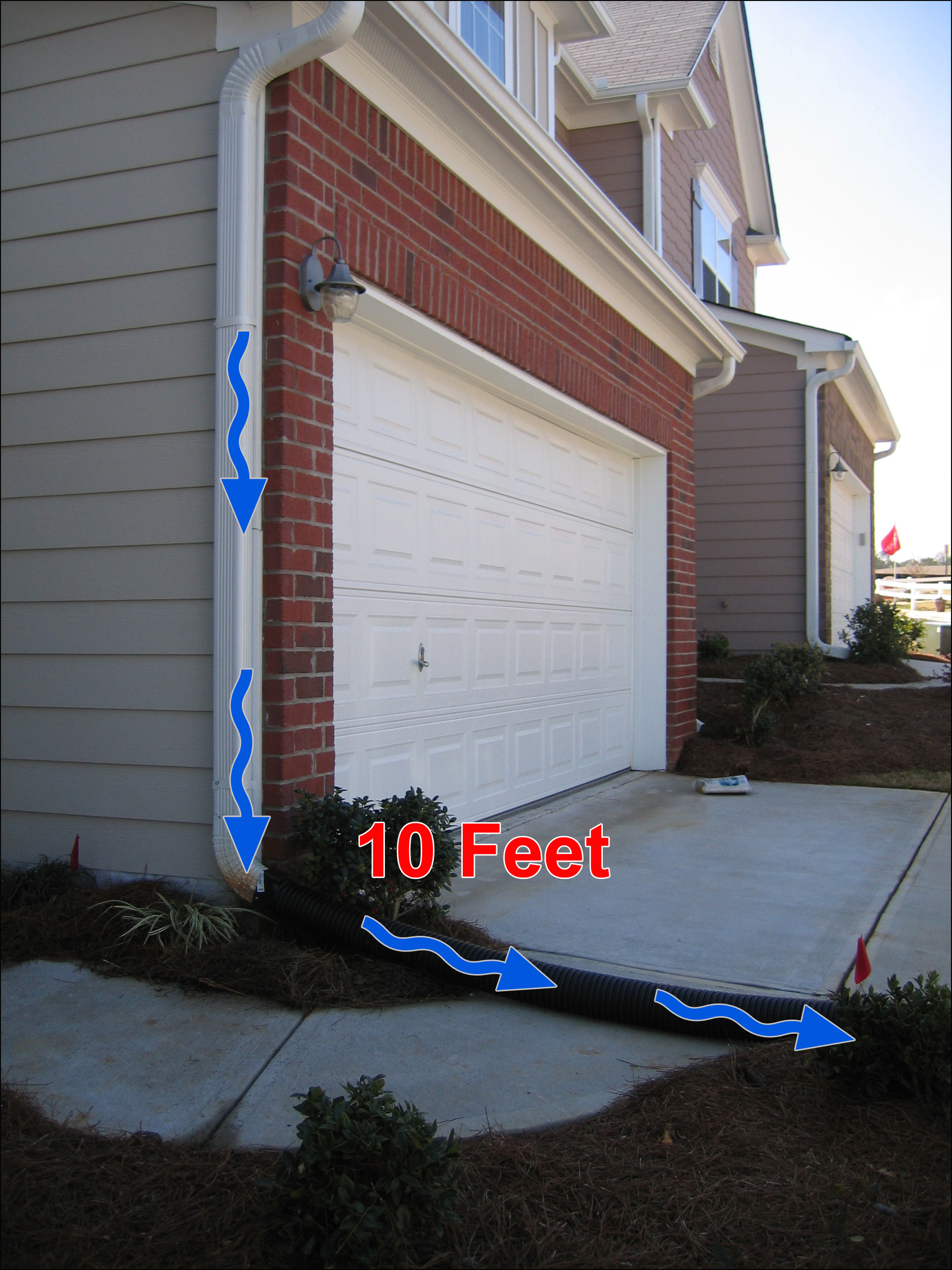
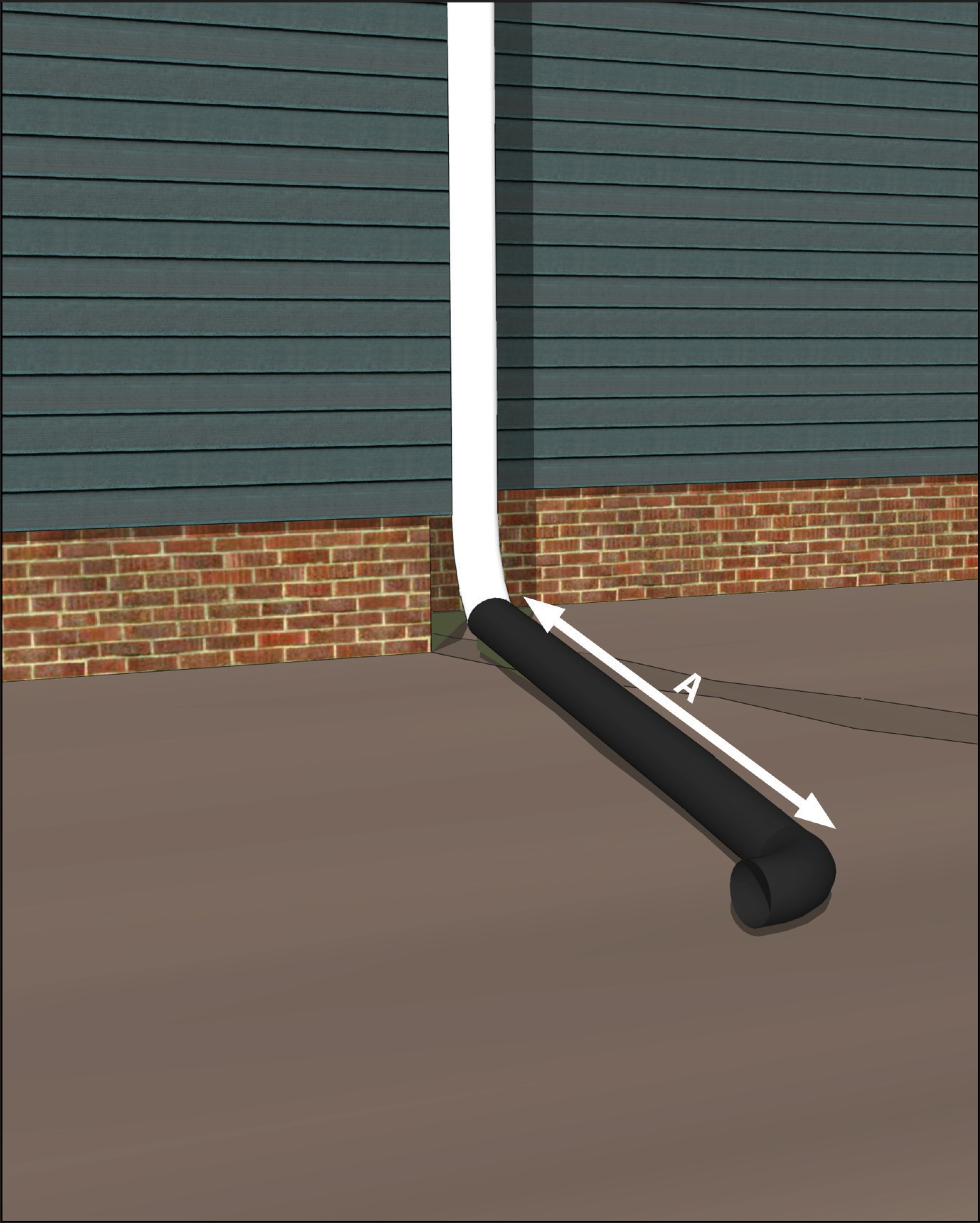
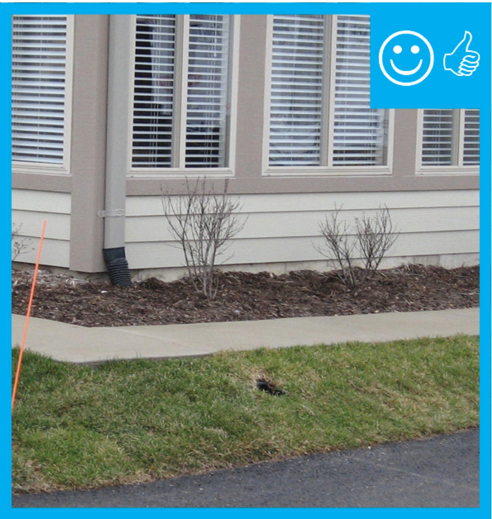
Right – The downspout pipe is far enough away from the foundation to prevent moisture problems
Image
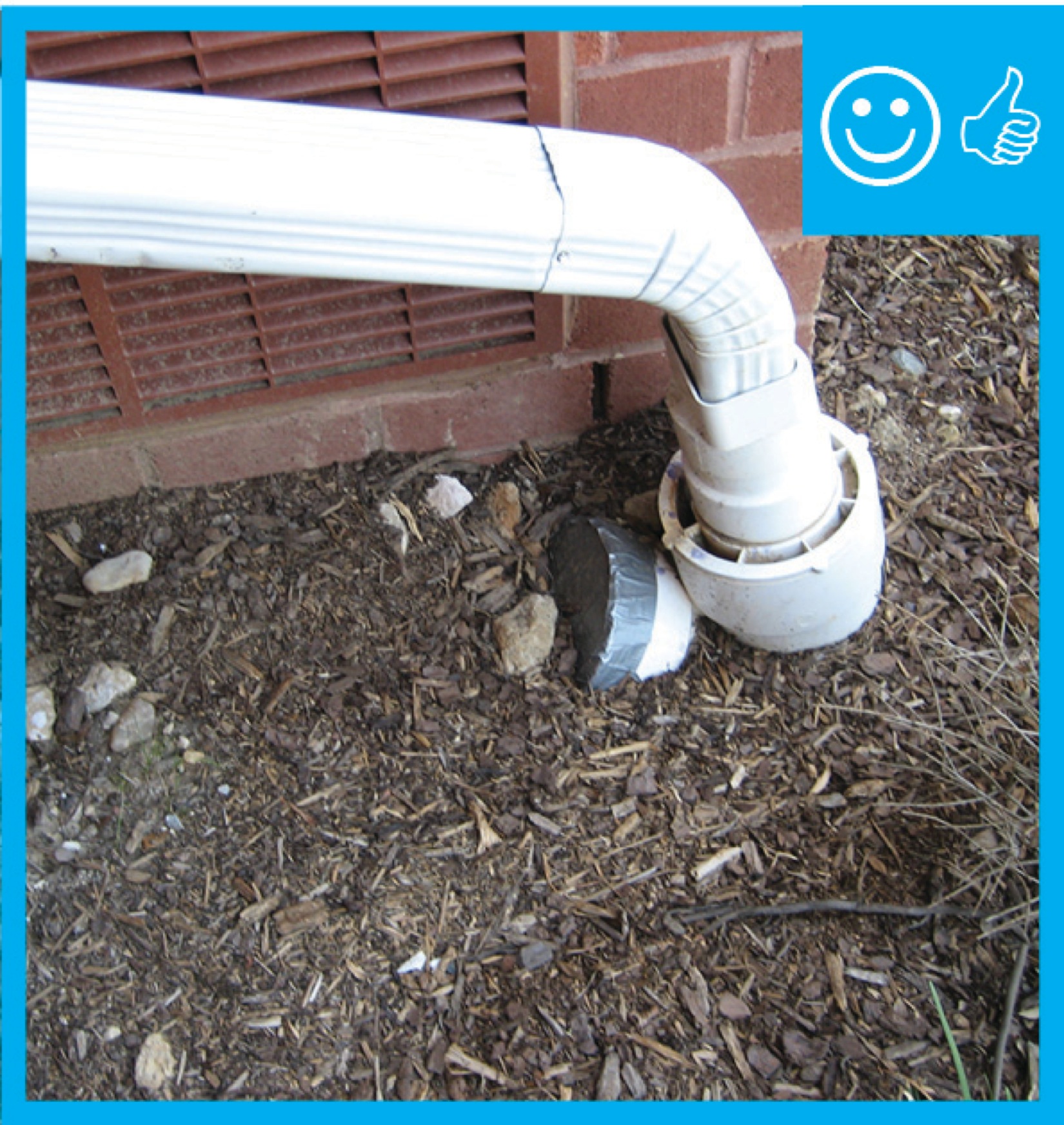
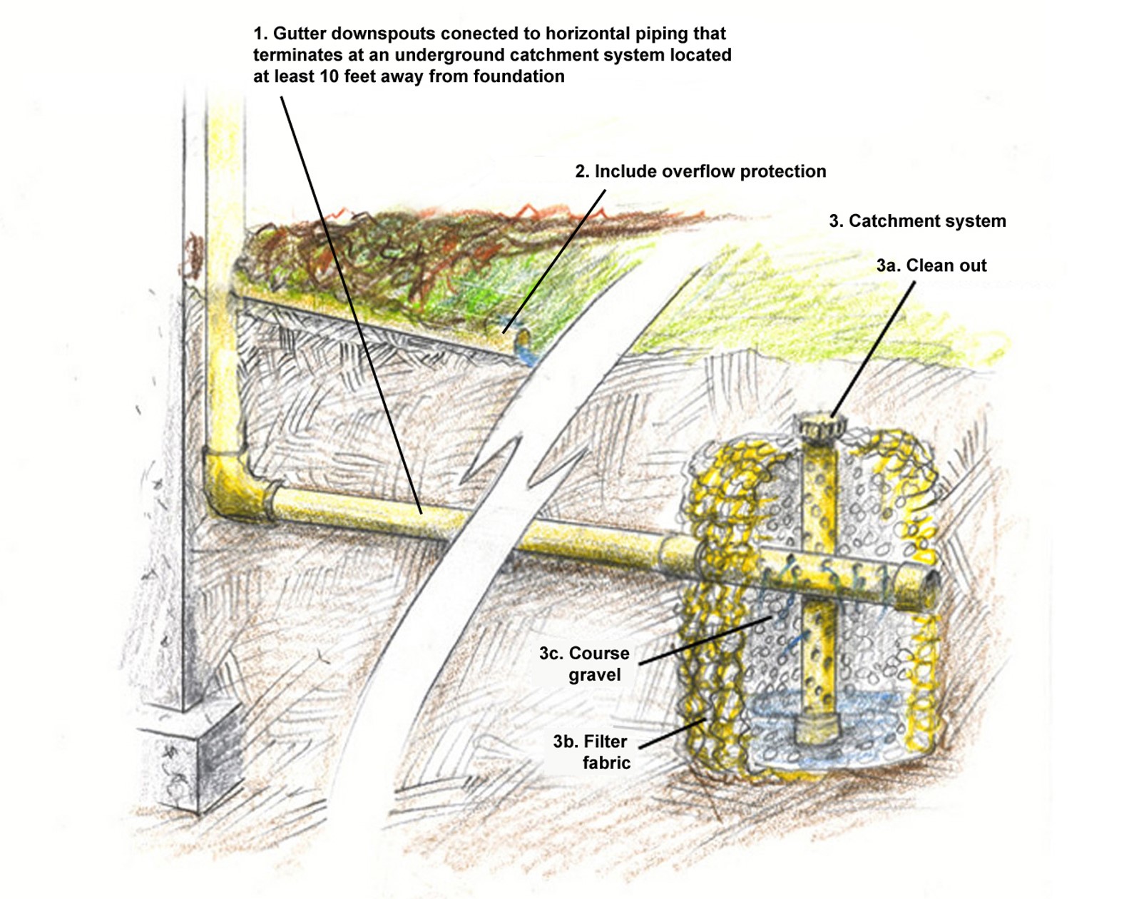
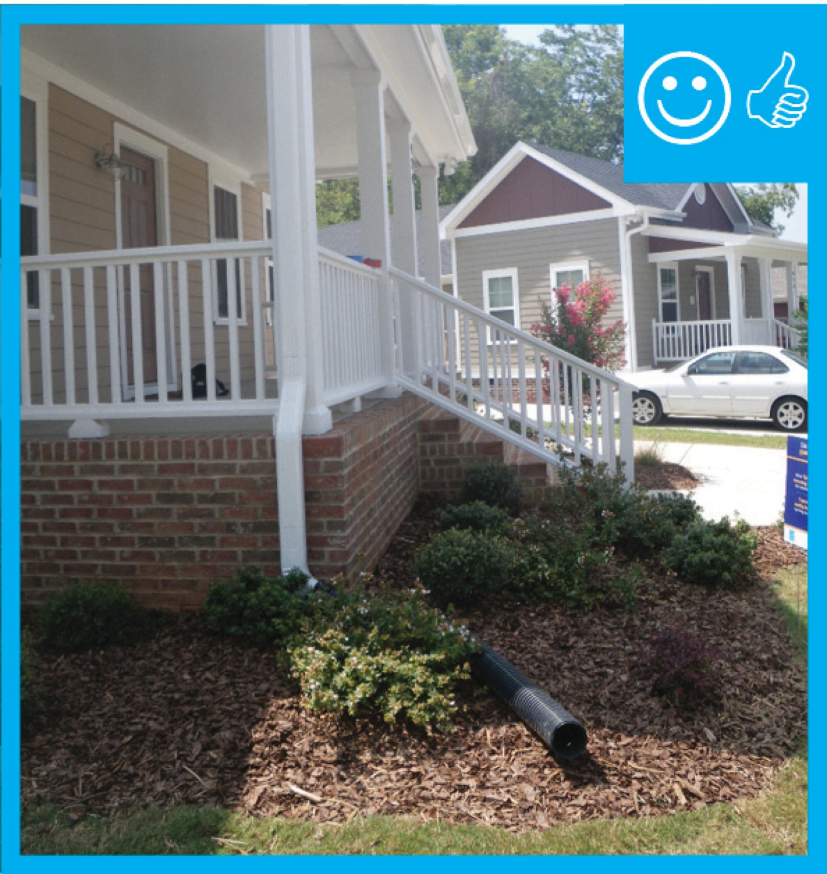
Right – The downspout terminates into a catchment system that moves water away from the foundation of the house
Image
Right – The drain slopes away from the foundation and terminates at the proper distance
Image

Image
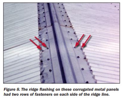
Right – The ridge flashing is secured with two rows of fasteners on each side of the ridge line
Image
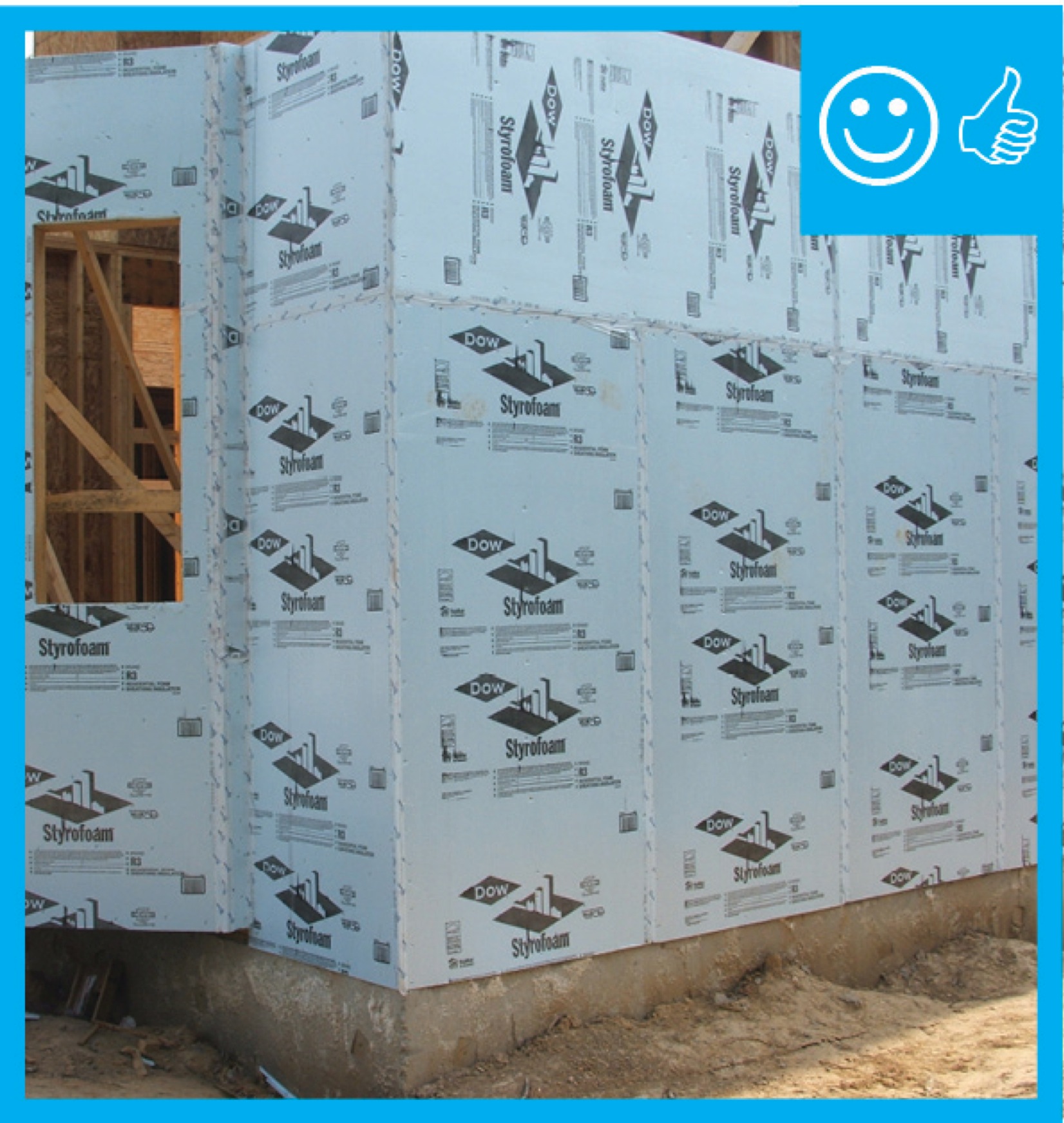
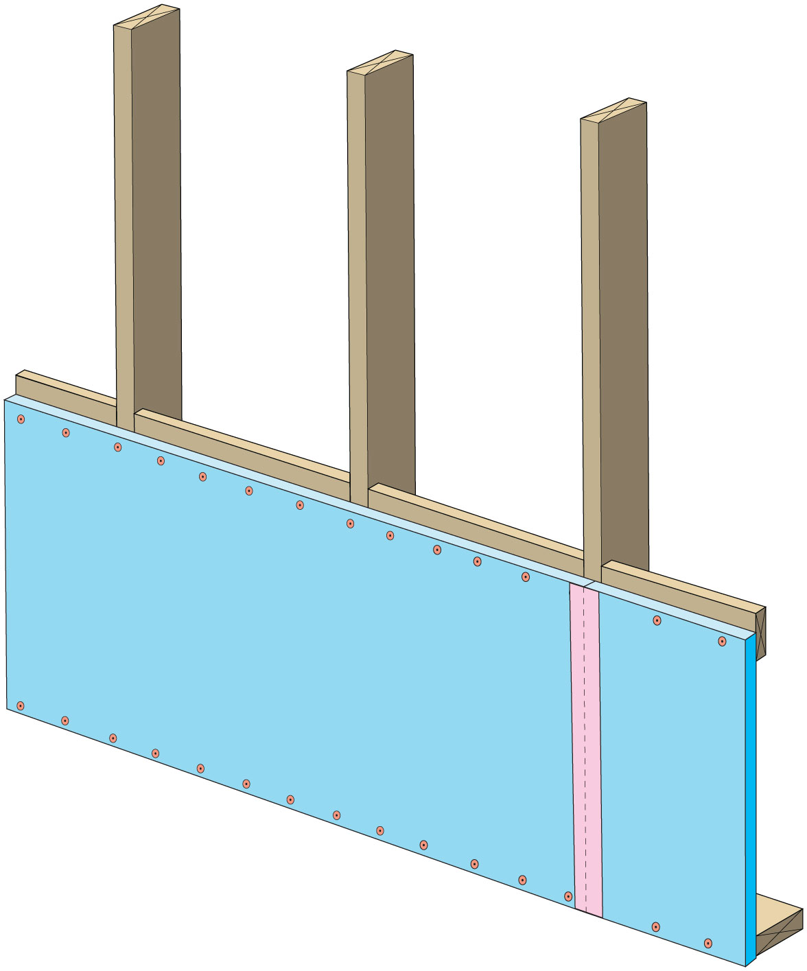
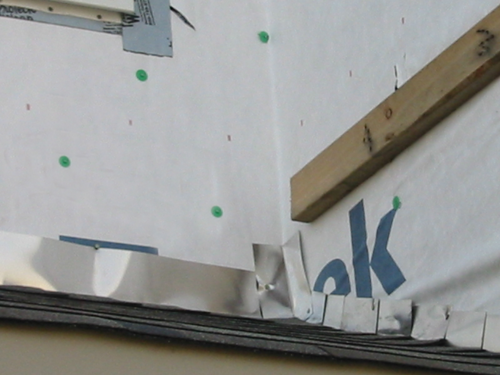
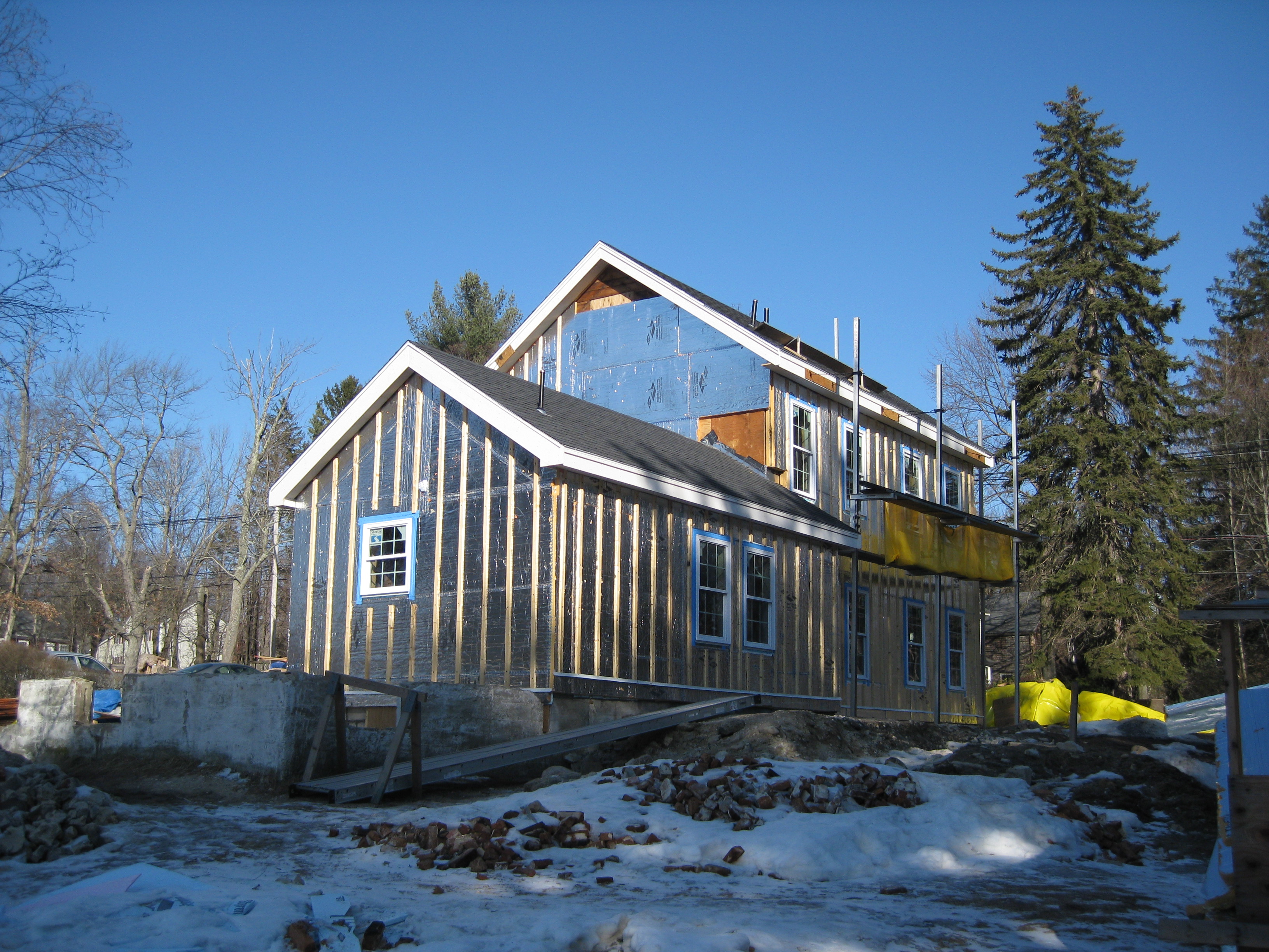
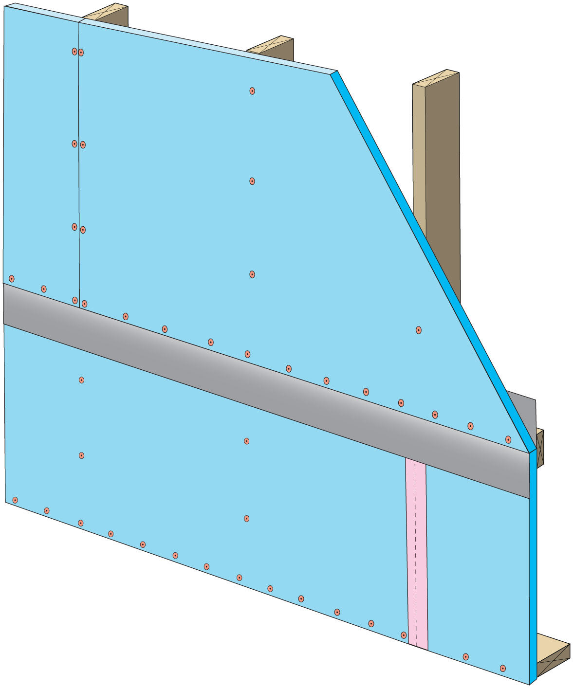
Right – The rigid insulation covers all exterior walls and all seams are taped to provide a complete drainage system
Image
Image
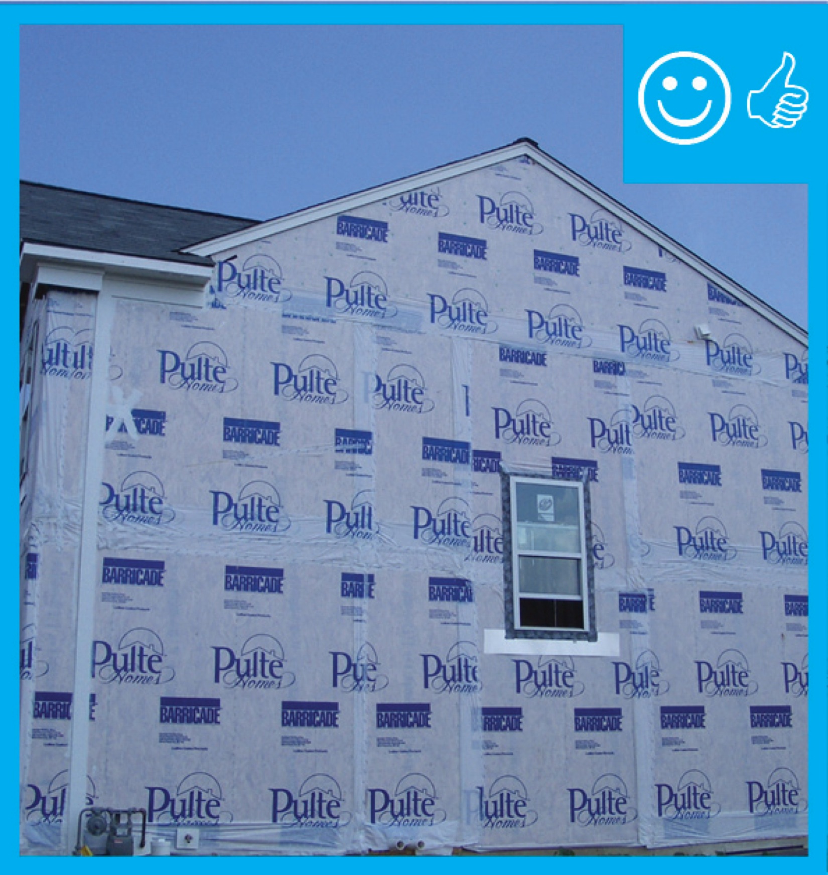
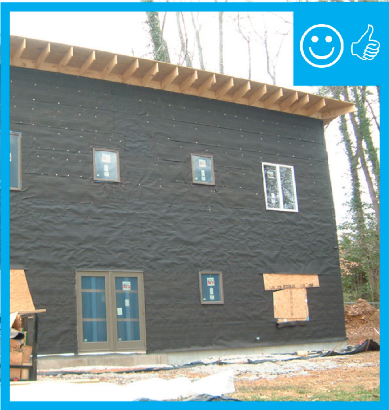
Right – The water-resistant barrier covers the entire house and the seams are taped to provide a complete drainage system
Image
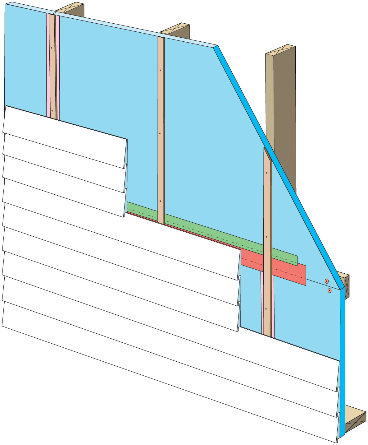
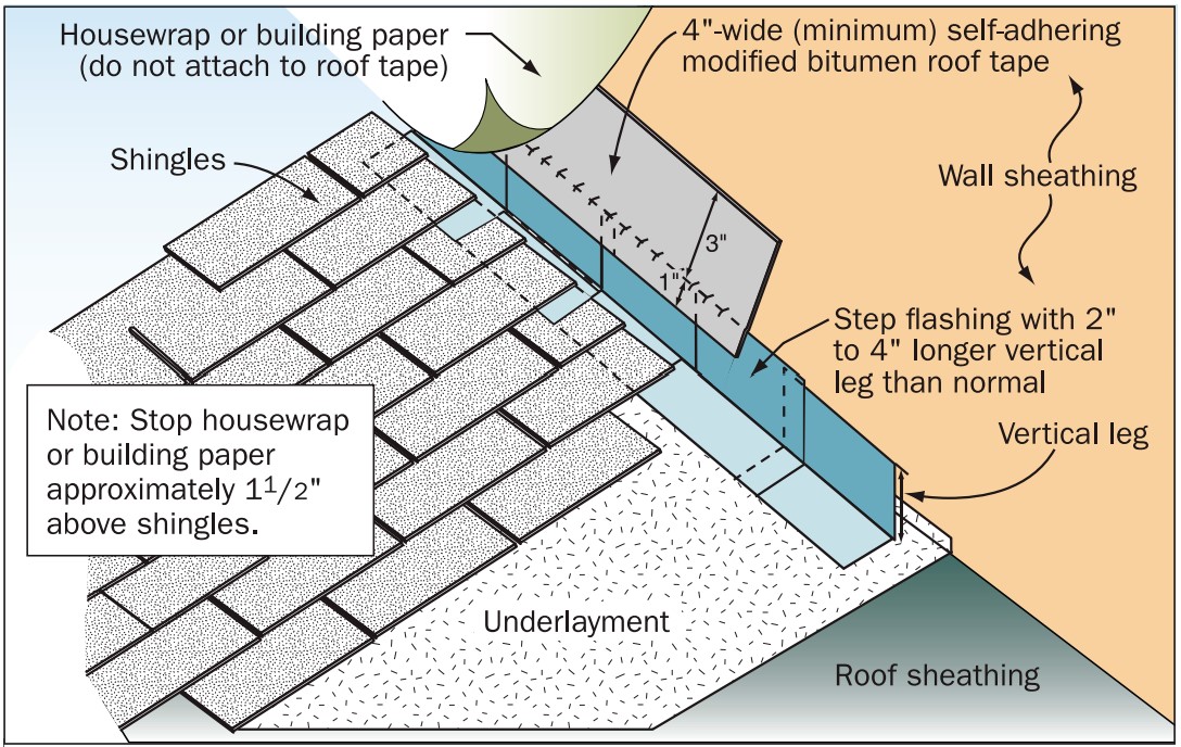
Right – The water-resistant barrier is layered over the step flashing to provide a complete drainage system
Image
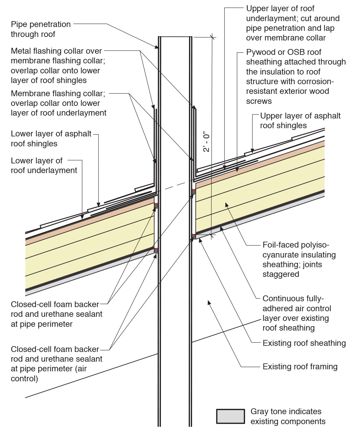
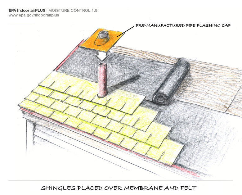
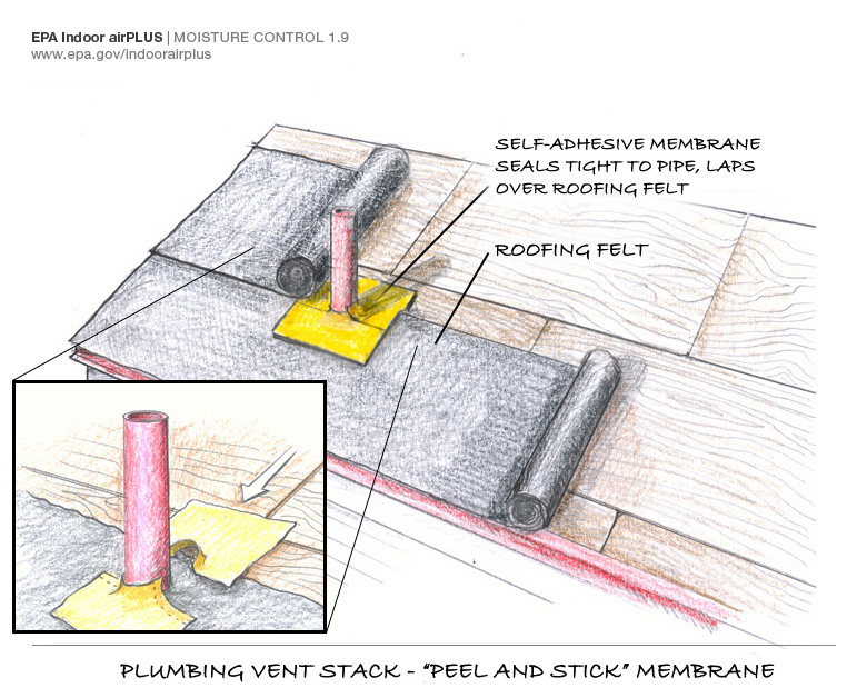
Right – There is a properly installed and layered self-sealing bituminous membrane at the roof penetration
Image
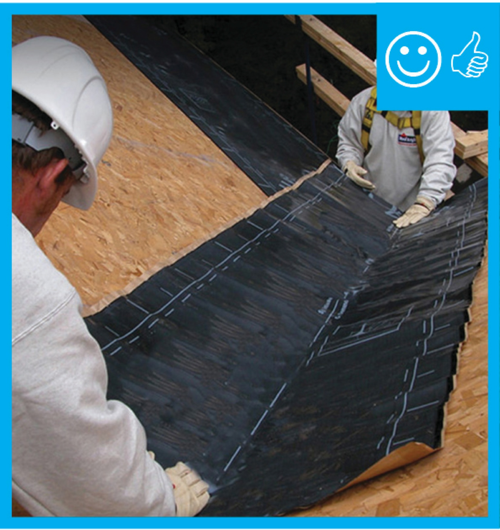
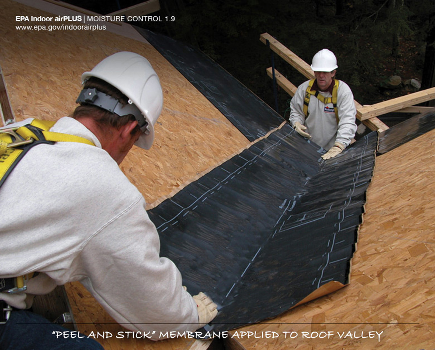
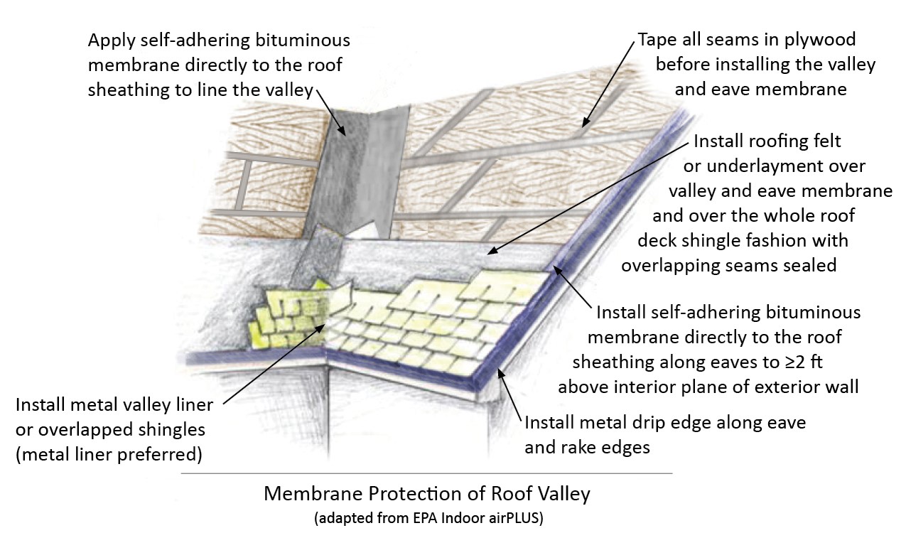
Right – There is a self-sealing bituminous membrane installed at the valley of the roof prior to the roof felt
Image
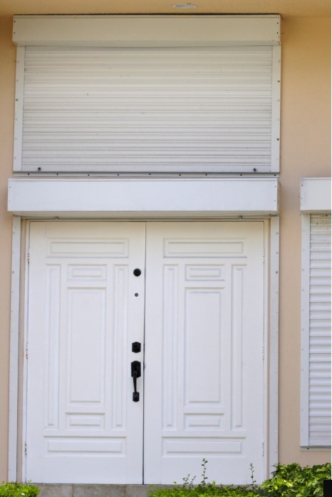
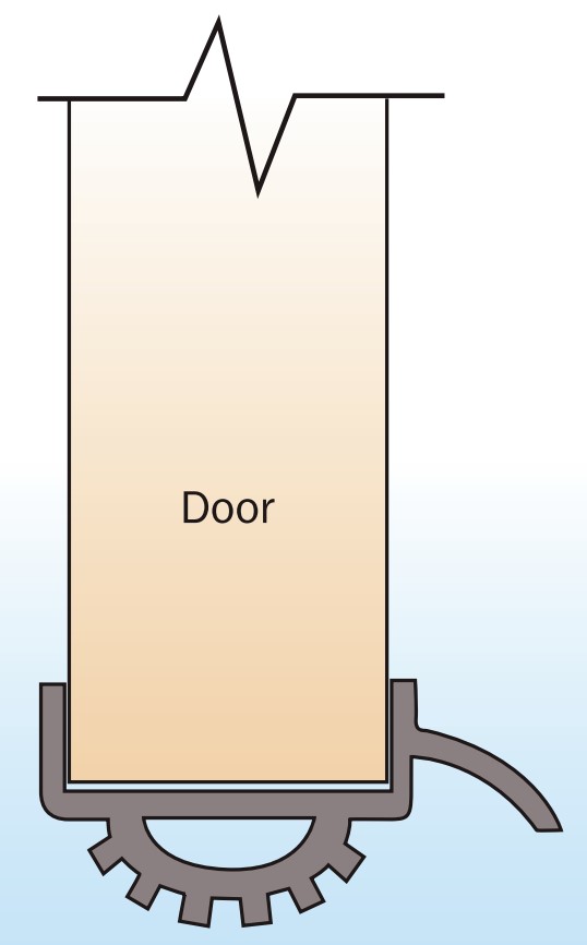
Right – This exterior door is installed to swing out and has storm protection shutters.
Image
Right – This low-slope flat roof assembly has continuity of both the air and water barriers
Image
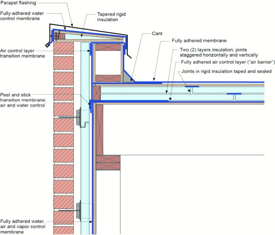
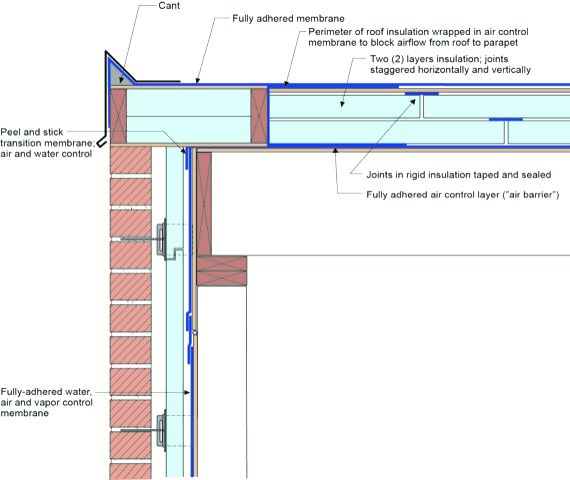
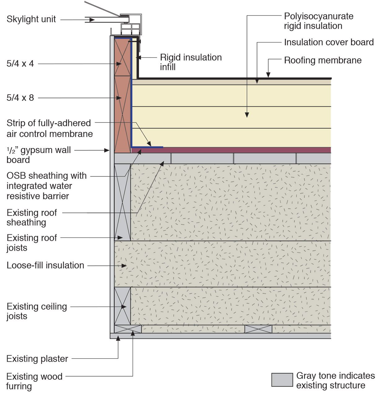
Right – This low-slope roof and parapet assembly has continuity of both the air and water barriers
Image
Right – This metal panel window shutter is installed in a track permanently mounted above and below the window frame and is secured with wing nuts to studs mounted on the track.
Image
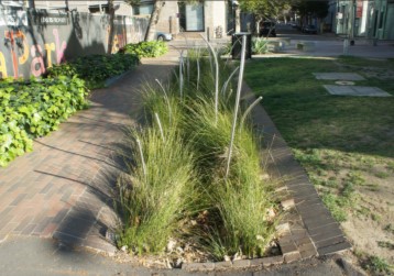
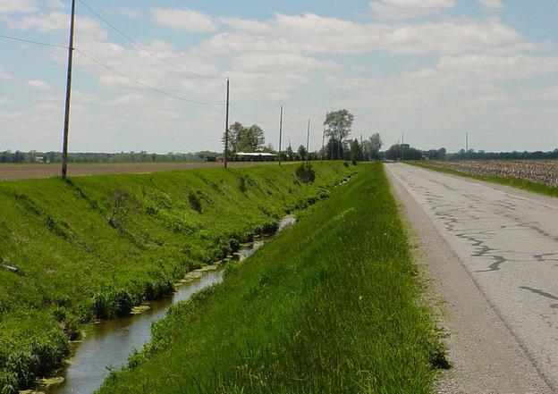
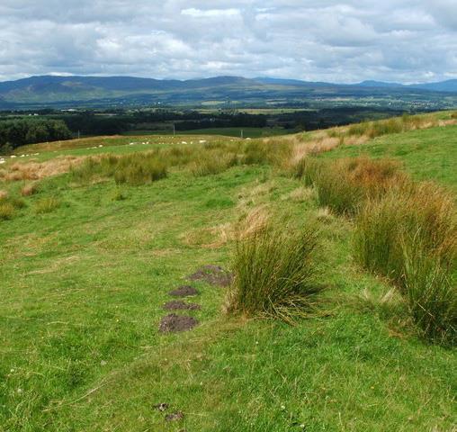
Right – This swale has sloped sides with appropriate vegetation to filter rainwater.
Image
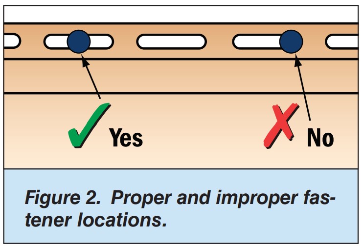
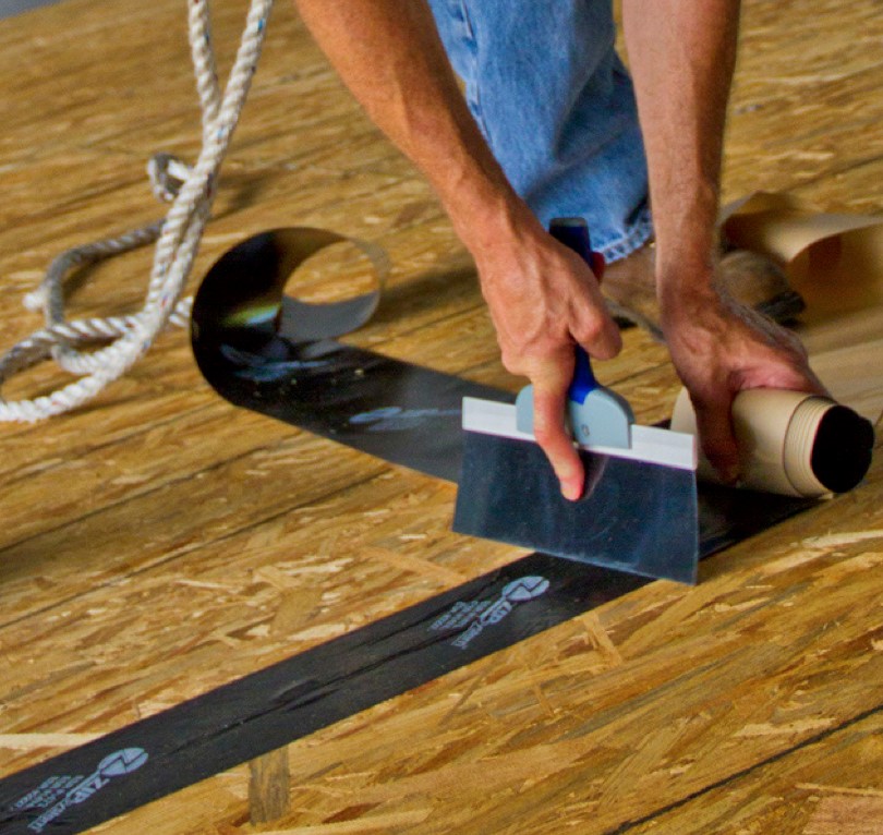
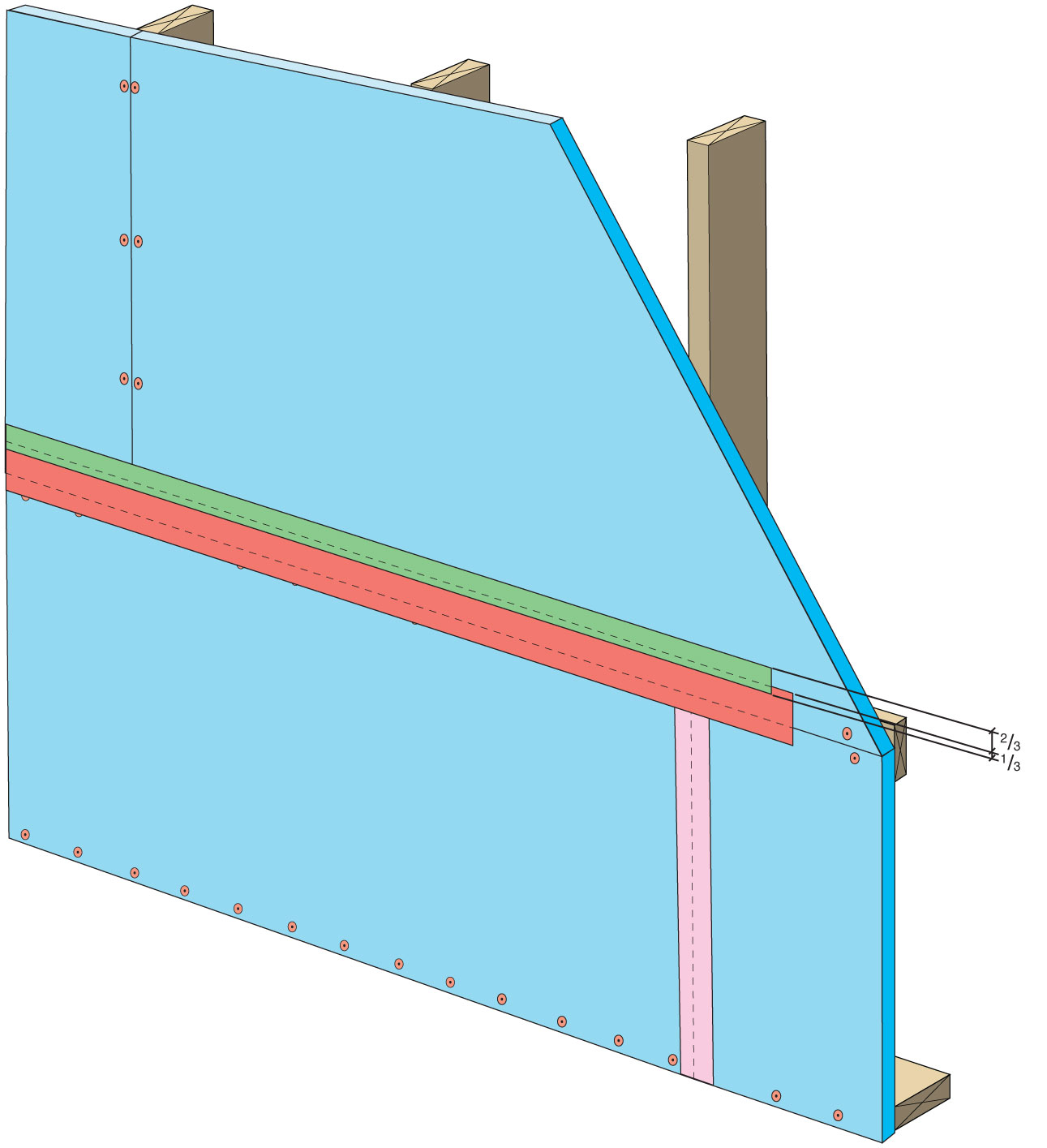
Right – Two-thirds of acrylic tape is offset above the joint and over and above the fasteners
Image
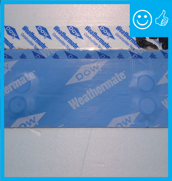
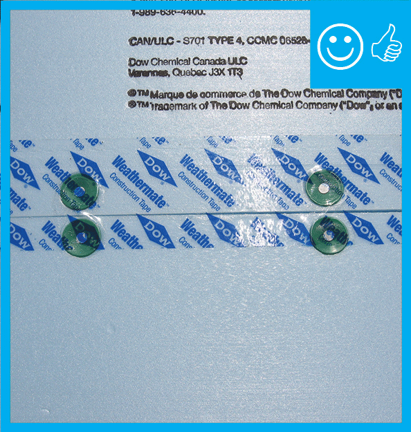
Right – two-thirds of the blue butyl flashing tape is above the sheathing seam; the top edge of the butyl flashing tape is covered with clear sheathing tape that is also offset so two-thirds is above the top edge of the butyl flashing.
Image
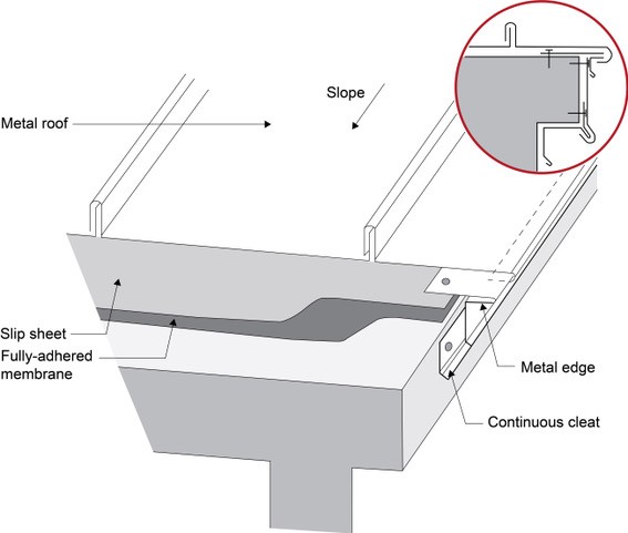
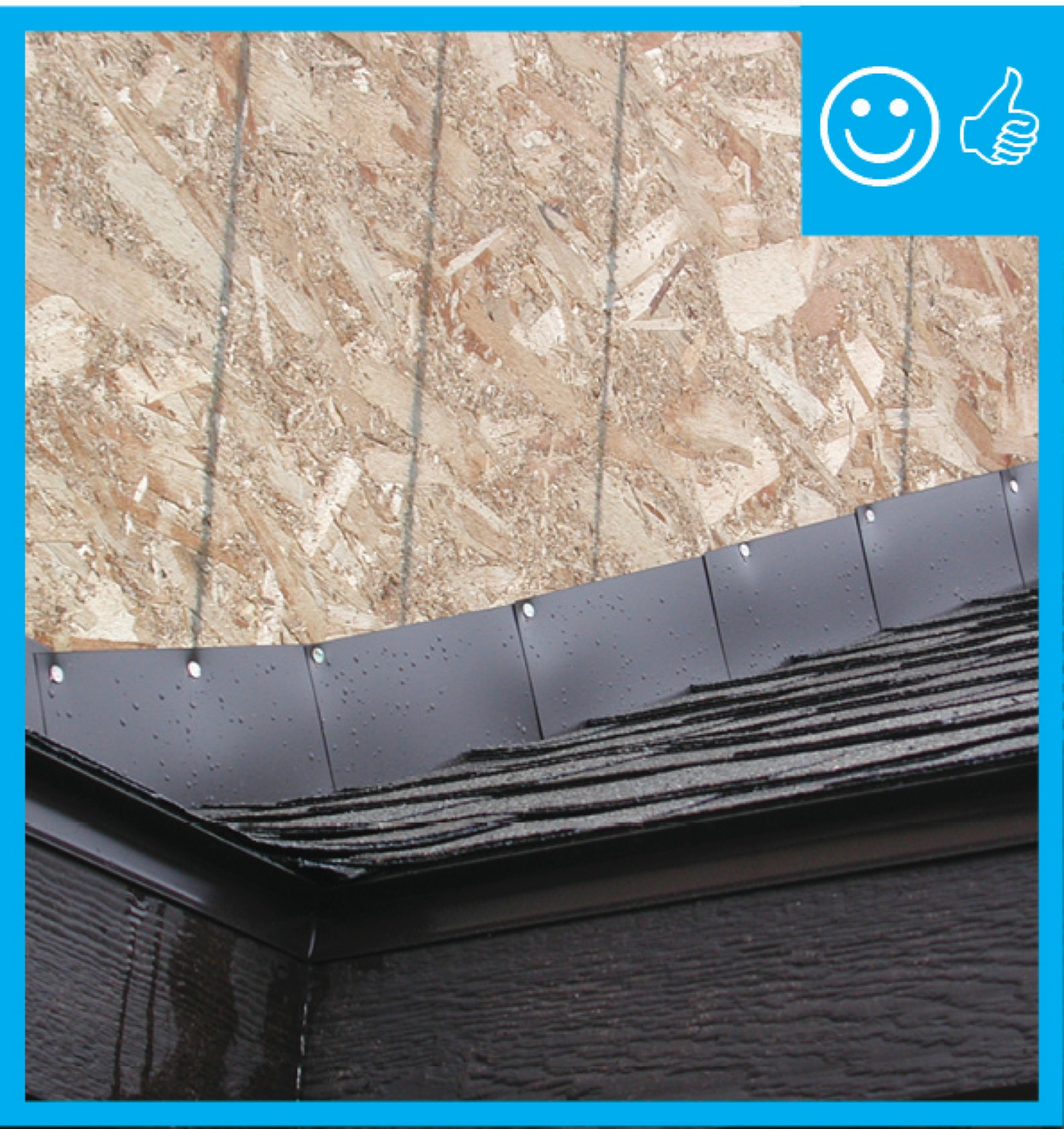
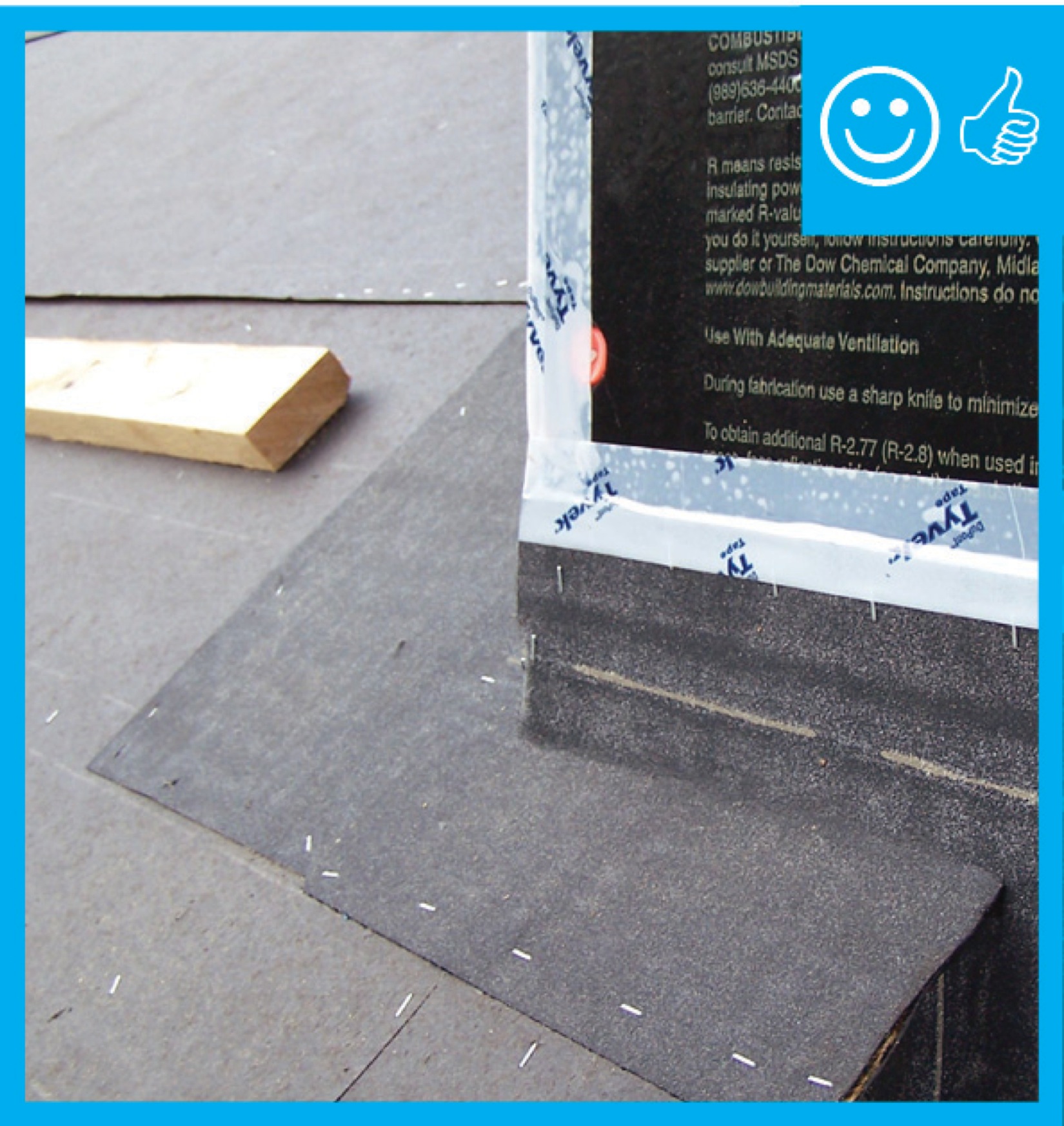
Right – Under metal roofing, sheathing is protected by metal edging over a fully adhered membrane and a slip sheet of loose laid building paper
Image
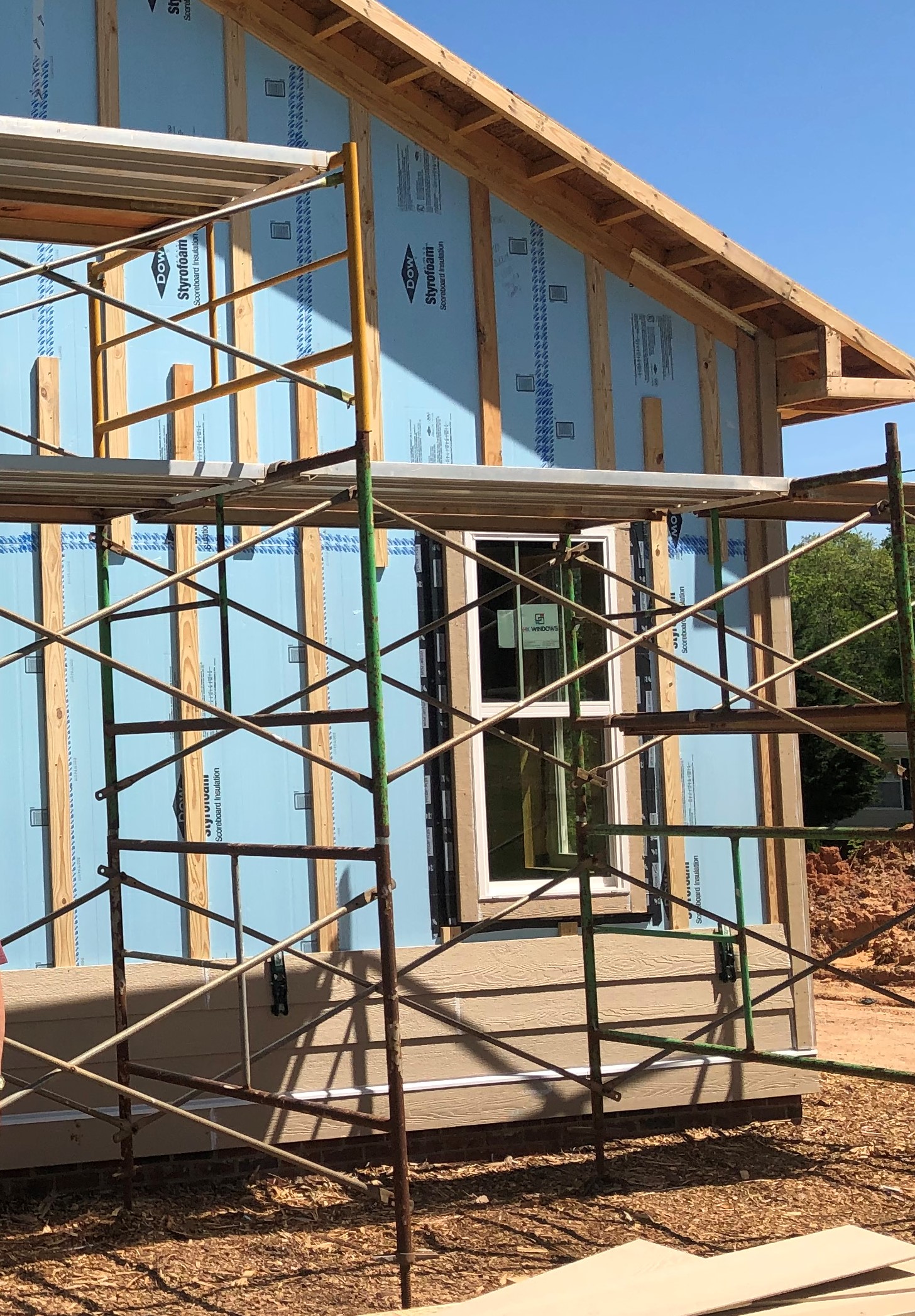
Rigid foam insulation can serve as the drainage plane when all seams are taped. Furring strips provide an air gap behind the cladding.
Image
Image
Image
Image
Image
Image
Image
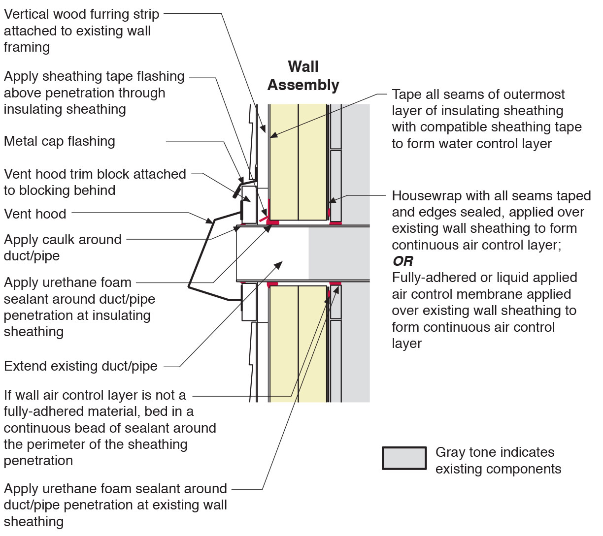
Section view of duct or pipe penetration through exterior wall showing flashing and air sealing details
Image
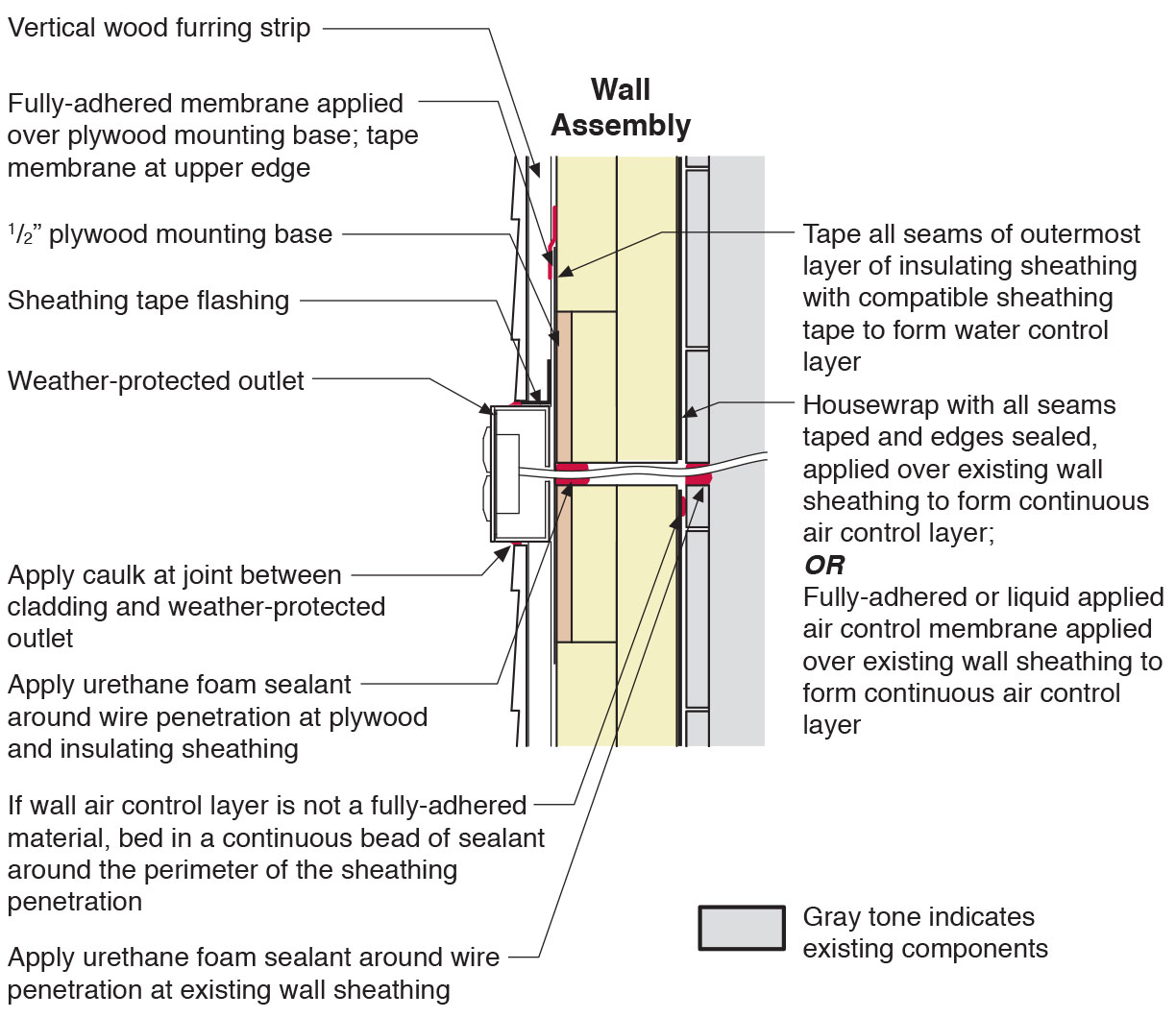
Section view of electric box installation in exterior wall showing flashing and air sealing details
Image

Shrubs, trees, and herbs create a tight network of roots and stems that bind the soil and slow the flow of water down hillsides.
Image

Soil types include sand, silt, and clay- the more sand, the more quickly the soil drains.
Image
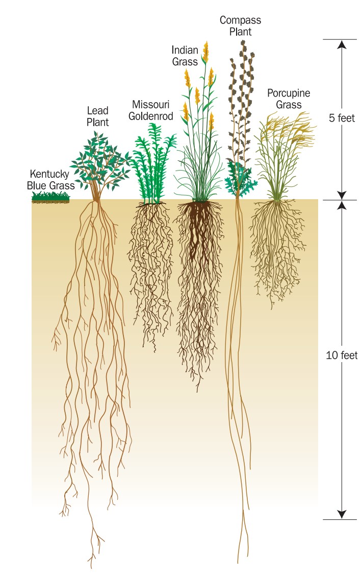
Some species of native prairie plants have much deeper root systems than Kentucky blue grass, increasing the ability of those plants to retain and filter stormwater
Image
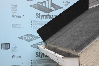
Step 1. Apply roof underlayment over roof deck and up the sidewall over the rigid foam insulation
Image
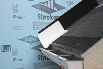
Step 2. Install shingle starter strip then kick-out diverter as first piece of step flashing.
Image
Step 4. Install remaining sidewall flashing, appropriate counter flashing, and shingles
Image
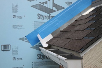
Step 5. Apply self-adhesive flashing over top edge of the wall flashing, diverter, and rigid foam insulation
Image
Image
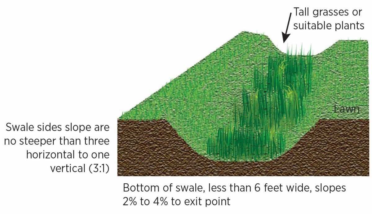
Swales are trapezoidal channels dug to receive storm-water overflow, with specific vegetation planted to improve aesthetics, filter stormwater runoff, and prevent erosion.
Image

Swales are troughs that collect site stormwater and filter it with vegetation, soil, and gravel layers.
Image

Image

Tape horizontal joint with minimum 3" wide tape placing tape offset high on the joint, adhearing to the upper sheet without wrinkles
Image
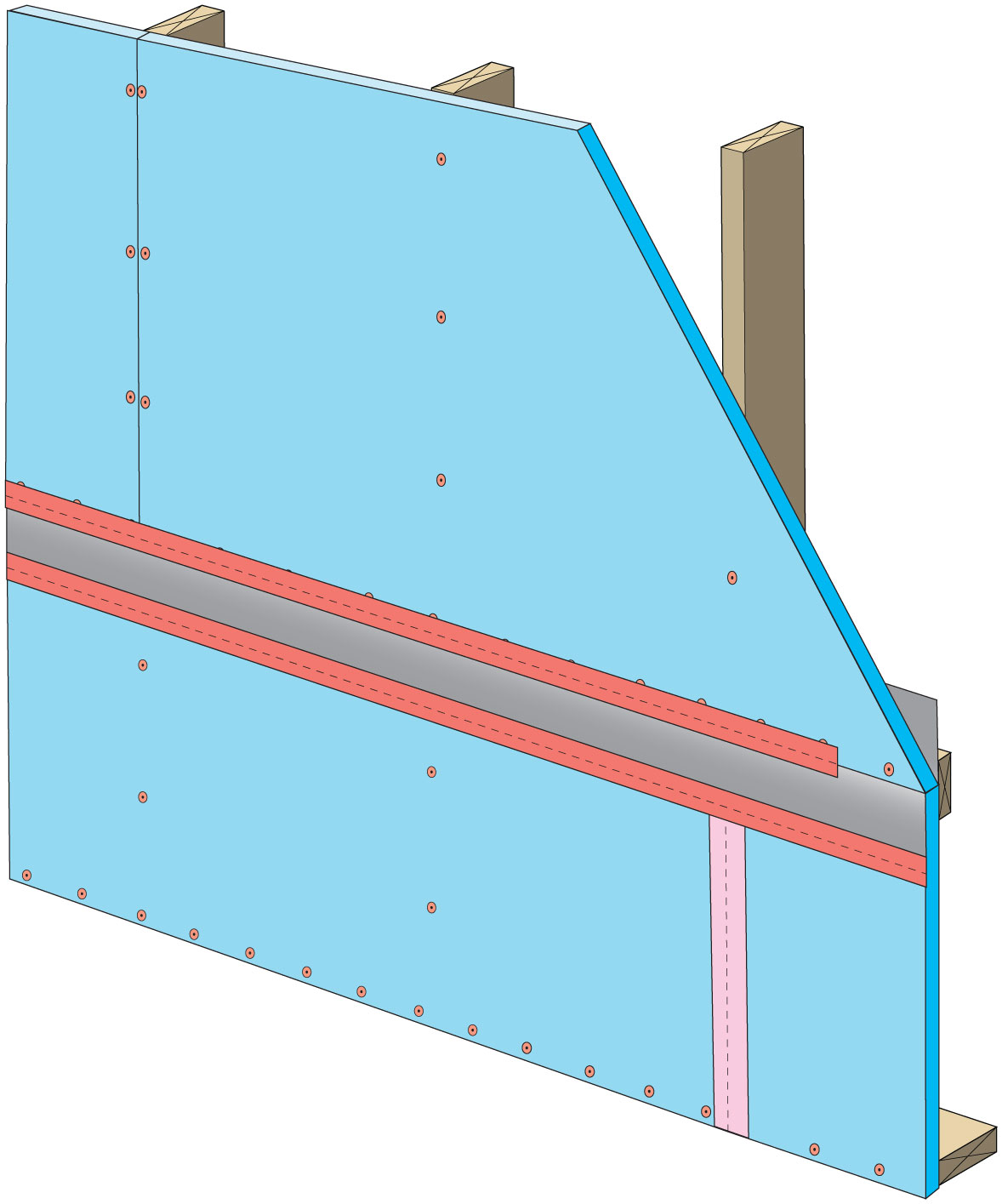
Tape the joint between the top insulation sheet and the Z-flashing with 2" wide tape to improve air tightness
Image
Image
Terminate 4" tape with 2" wide tape placing tape offset high on the joint, 2/3 of the tape should be adhered to the sheet of insulation
Image
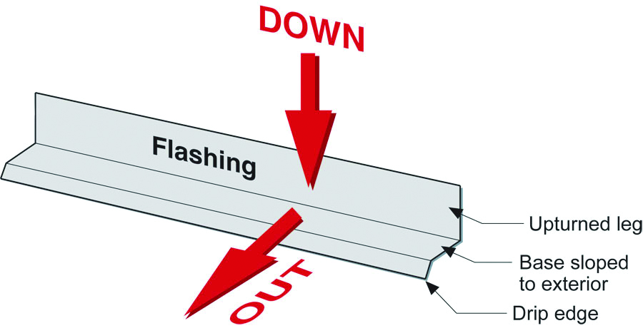
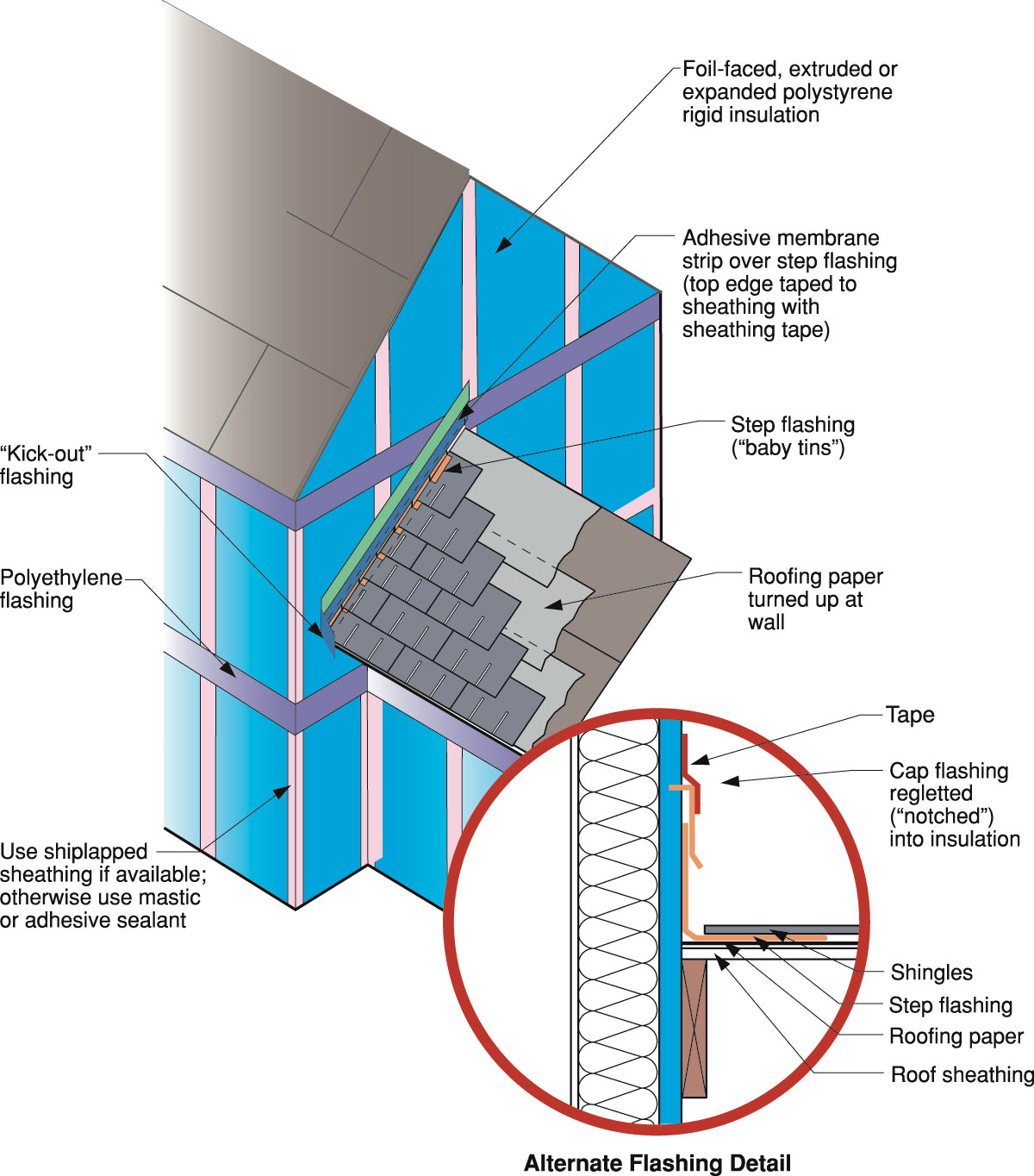
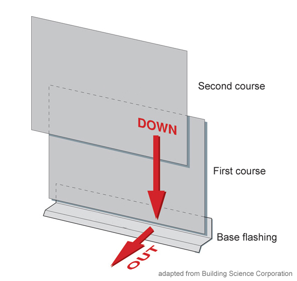
The “down” and “out” approach to flashing – metal flashing directs water down and out of building assemblies
Image
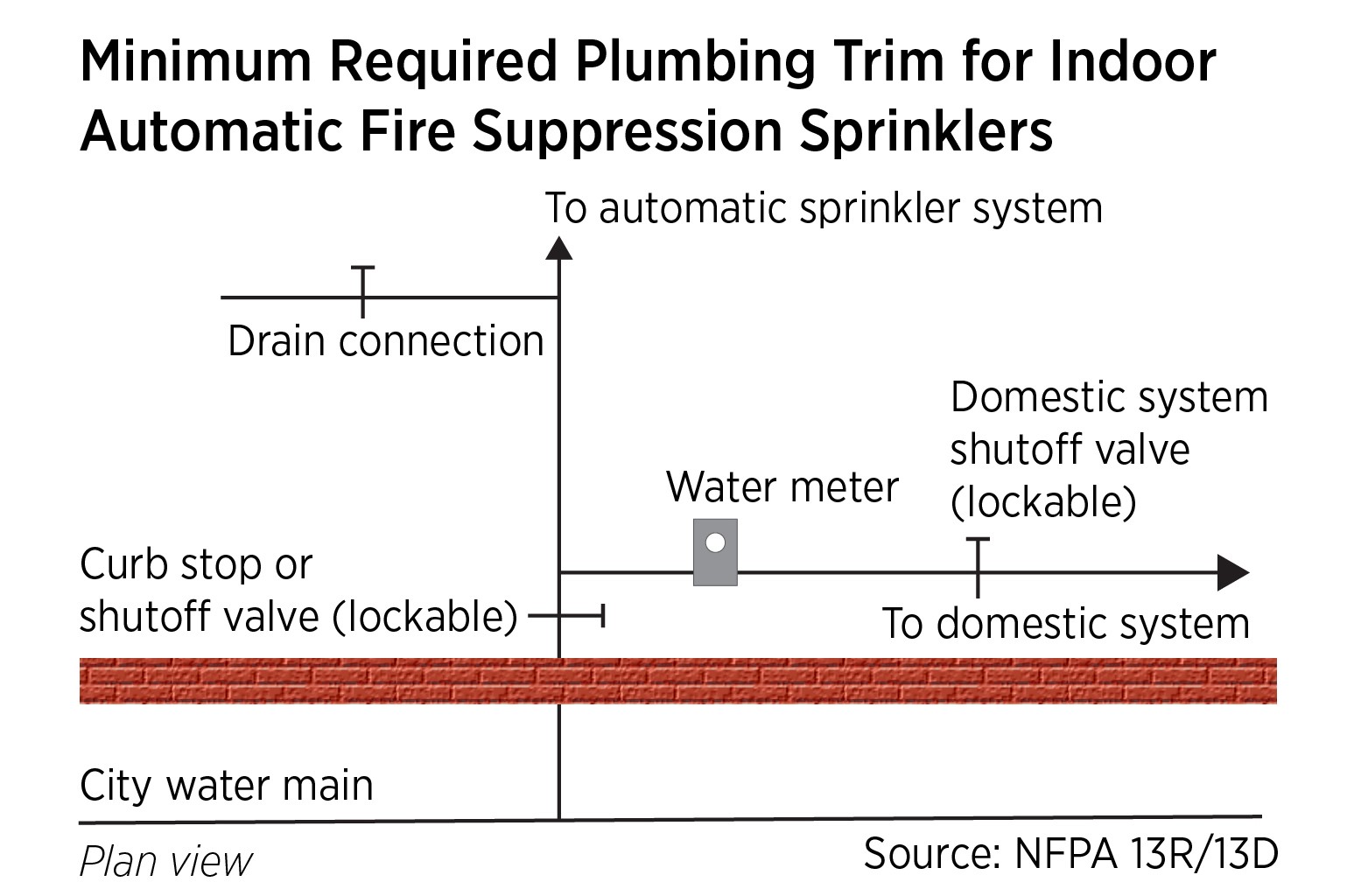
The minimum required plumbing connections and trim for fire sprinkler connection to municipal water with a standalone wet sprinkler system.
Image
Image
Image
Image
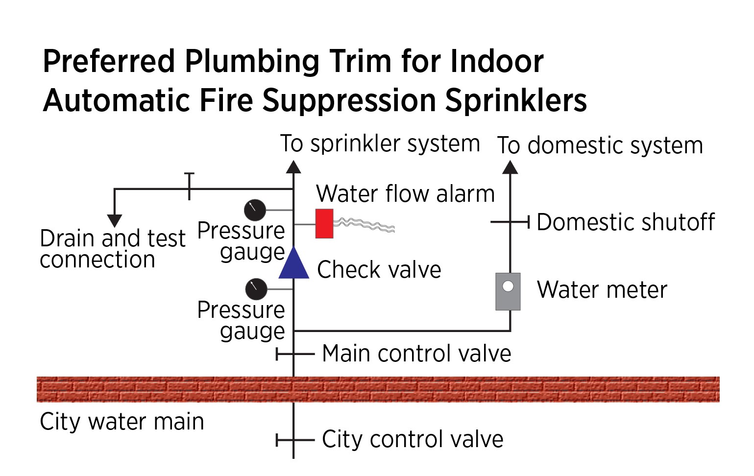
The preferred method for fire sprinkler connection to municipal water with a standalone, wet sprinkler system.
Image
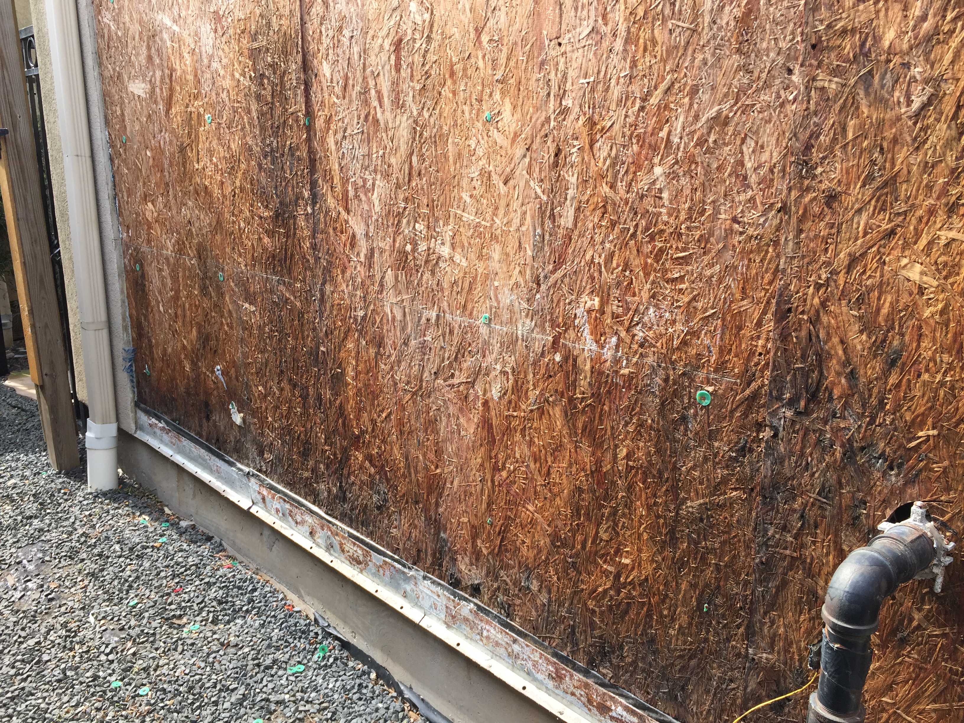
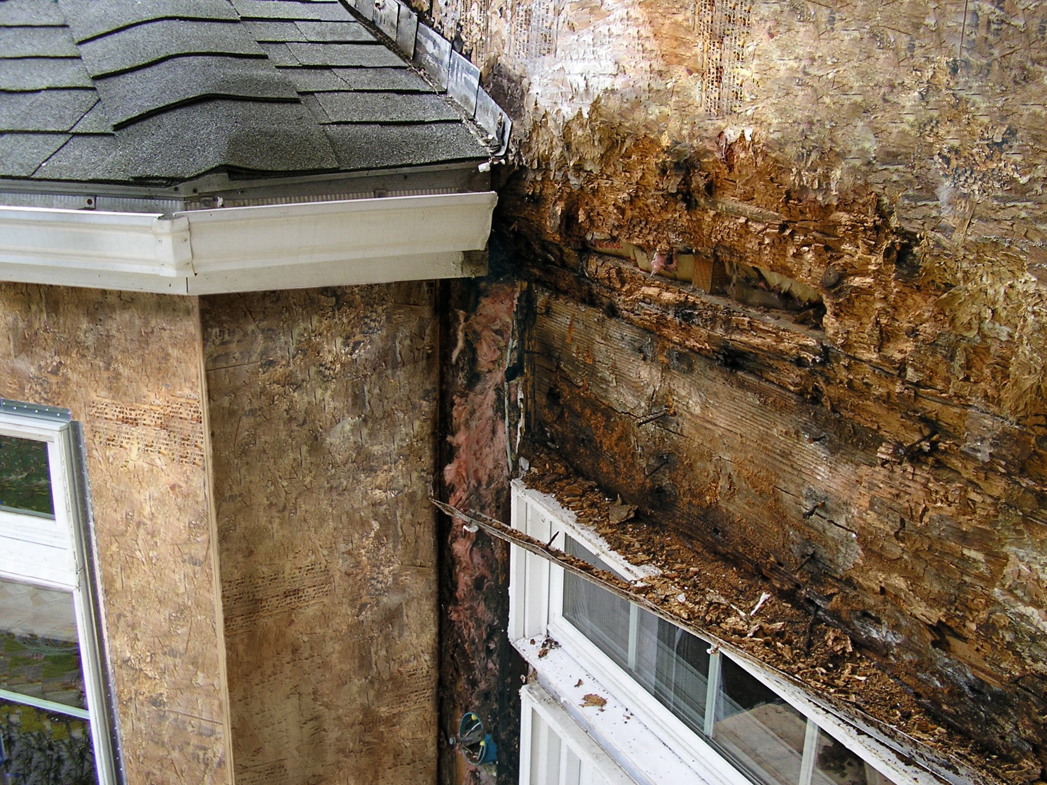
The sheathing has rotted because there was not a sufficient drainage gap behind the stucco cladding
Image
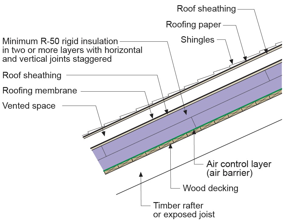
The ventilation space in this vented over-roof keeps the roof cool to prevent ice dams over the unvented attic
Image
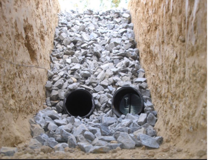
This double French drain provides drainage for a significant volume of storm water.
Image
This farmhouse was retrofit by removing the existing siding and adding taped insulated sheathing and battens before installing new siding
Image

This home was designed with continuous roof vents and few roof penetrations, allowing more room for the solar shingles that integrate with the asphalt shingles installed to meet IBHS Fortified Roof criteria for increased resistance to high winds and rain
Image
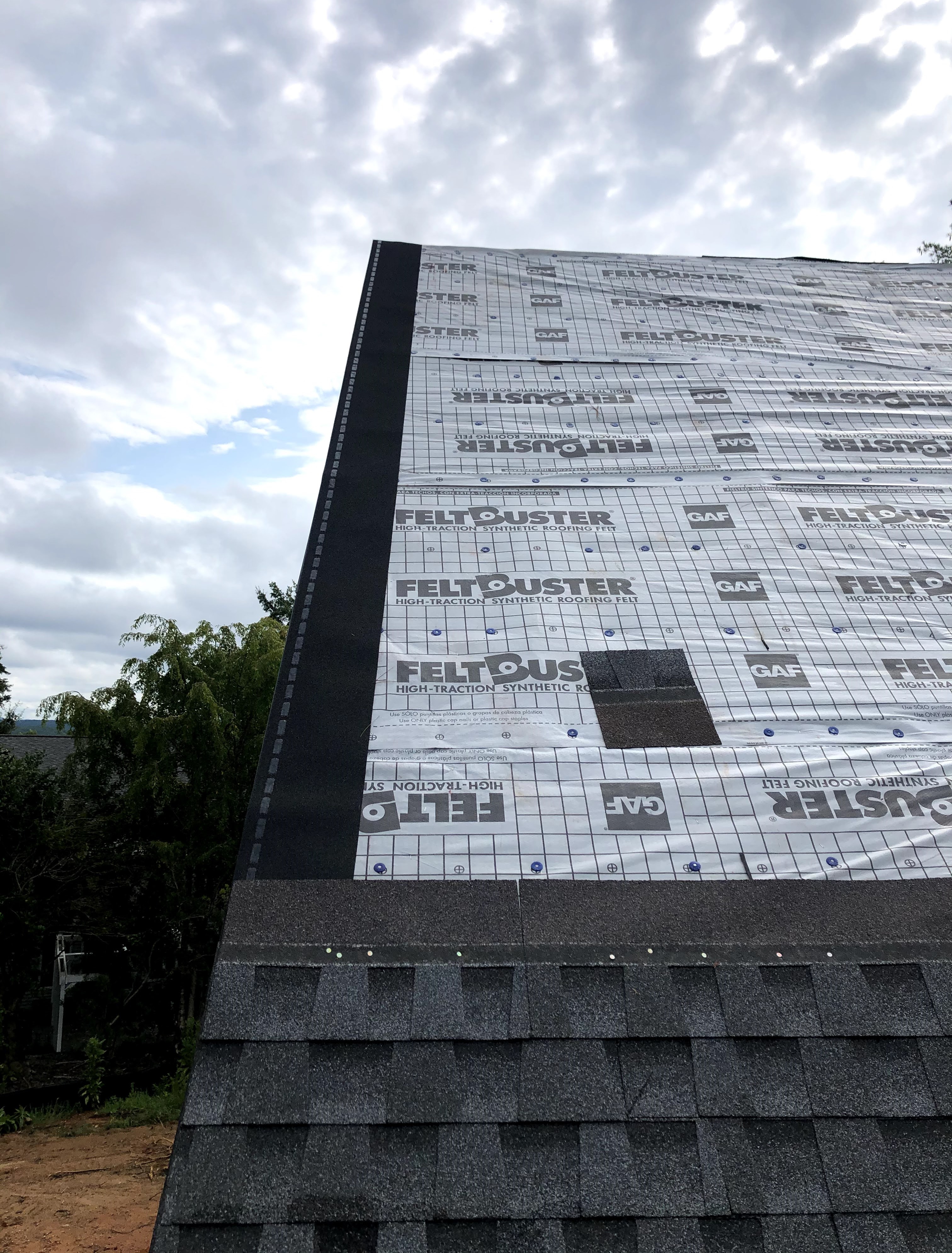
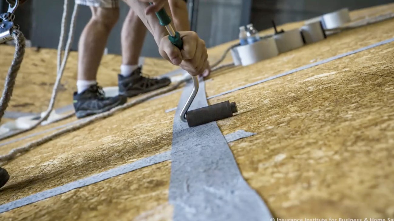
This roof was constructed to meet the IBHS Fortified Roof standard by sealing the decking seams with flashing tape, installing synthetic roof underlayment secured with metal drip edge and nailed every six inches, and using self-adhered starter shingles.
Image
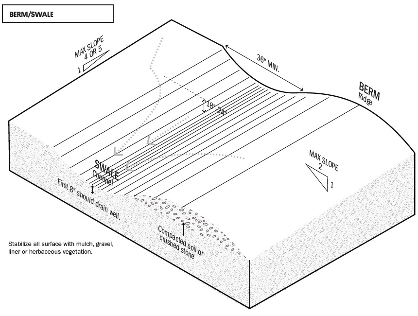
This swale and berm slow the flow of stormwater across a site to minimize erosion.
Image
Image
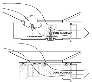
Using outdoor misters or spray fountains can cool the outside air before it enters the house
Image
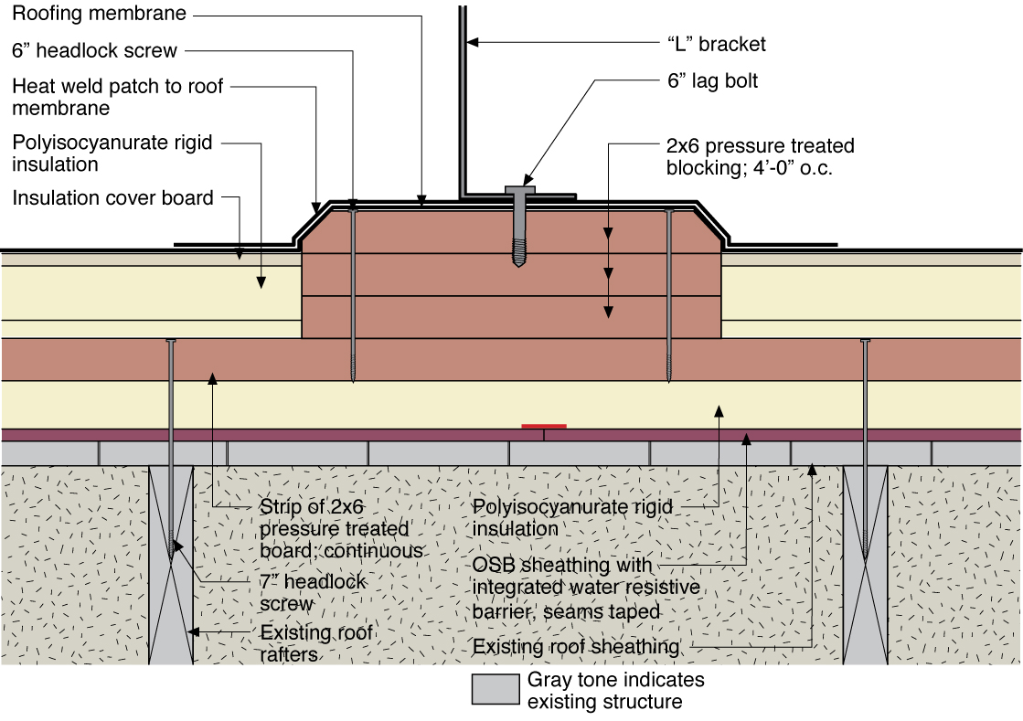
Water management detail for a solar panel rack mounting block installed in rigid foam that was installed over an existing roof
Image
Image
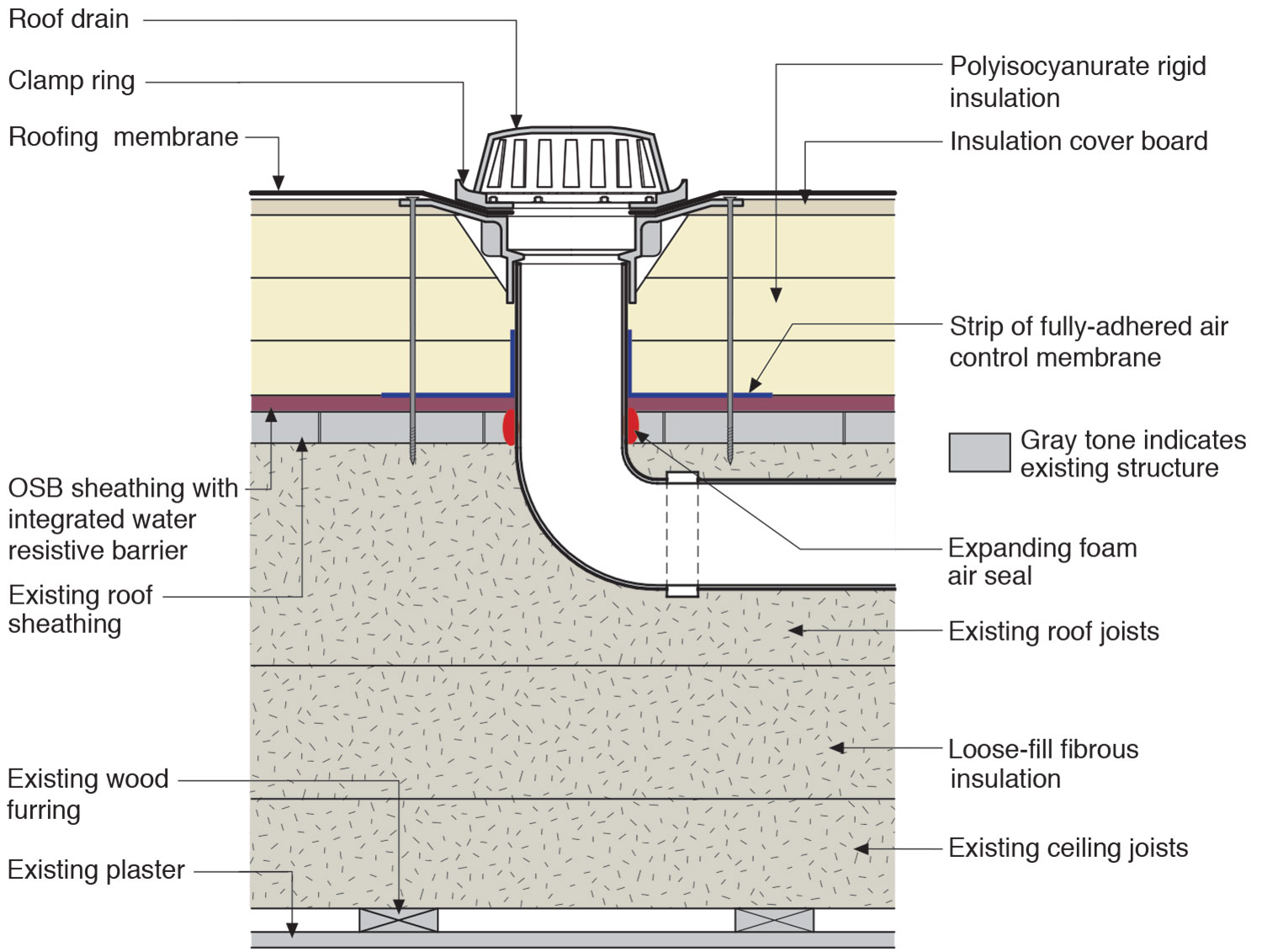
Water management details for a roof drain installed along with rigid foam on a flat roof
Image
Image
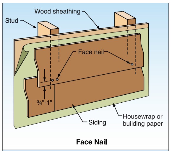
With fiber cement siding, face nail rather than blind nail where the design wind speed is ≥100 mph.
Image
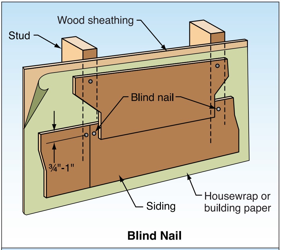
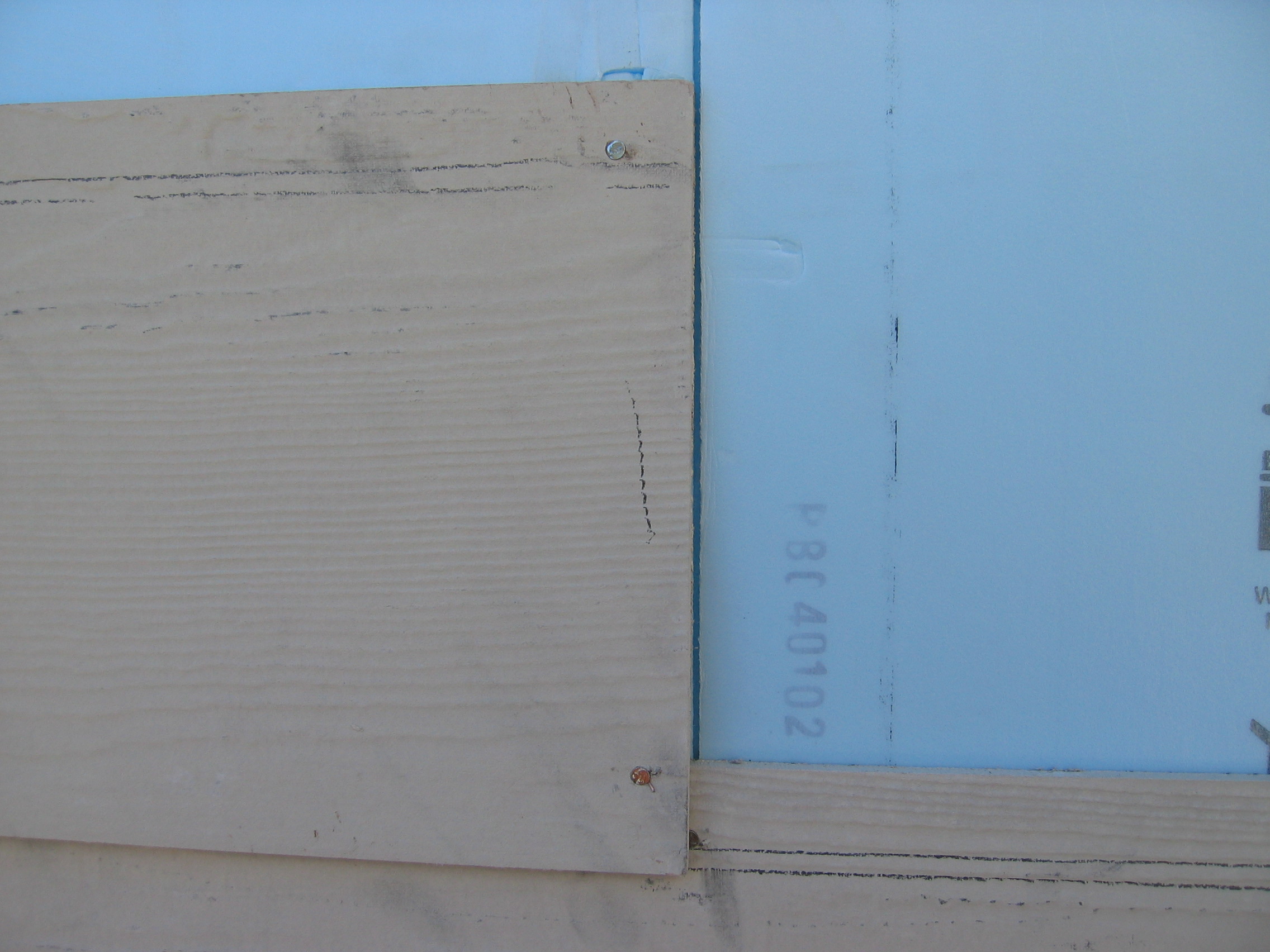
With fiber cement siding, place blind nails 3/4 to 1 inch from top edge and > 3/8 inch in from butt ends.
Image
Image
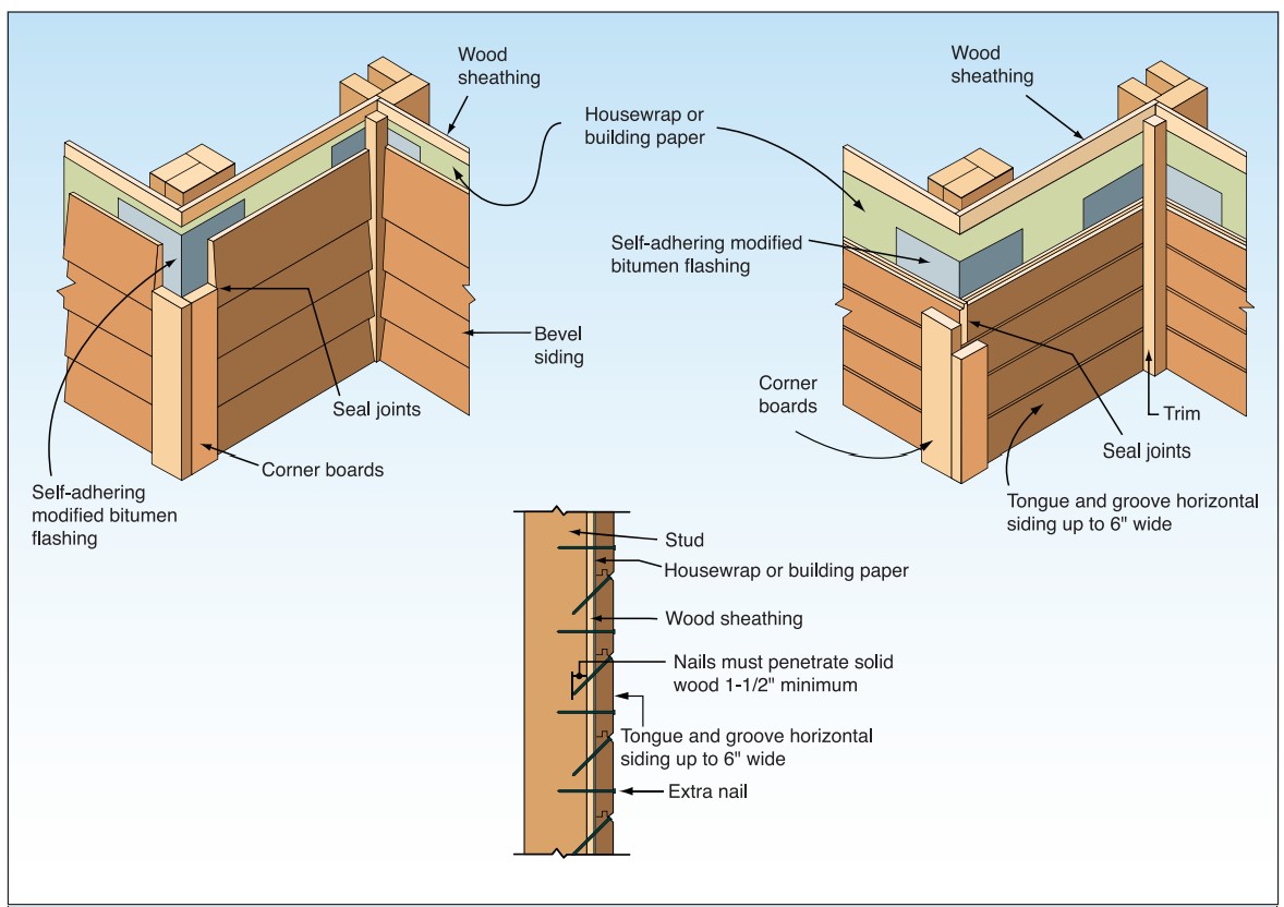
Wood siding installation details to improve resistance to wind-driven rain at corners.
Image
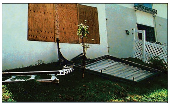
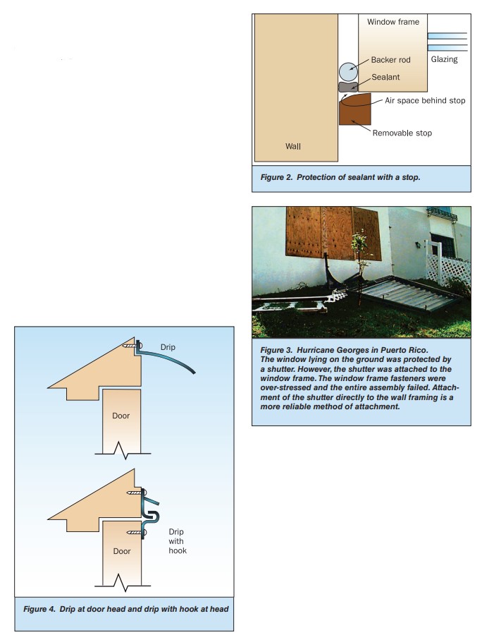
Wrong - The window lying on the ground was protected by a shutter but the shutter was attached to the window frame, rather than directly to the wall framing.
Image

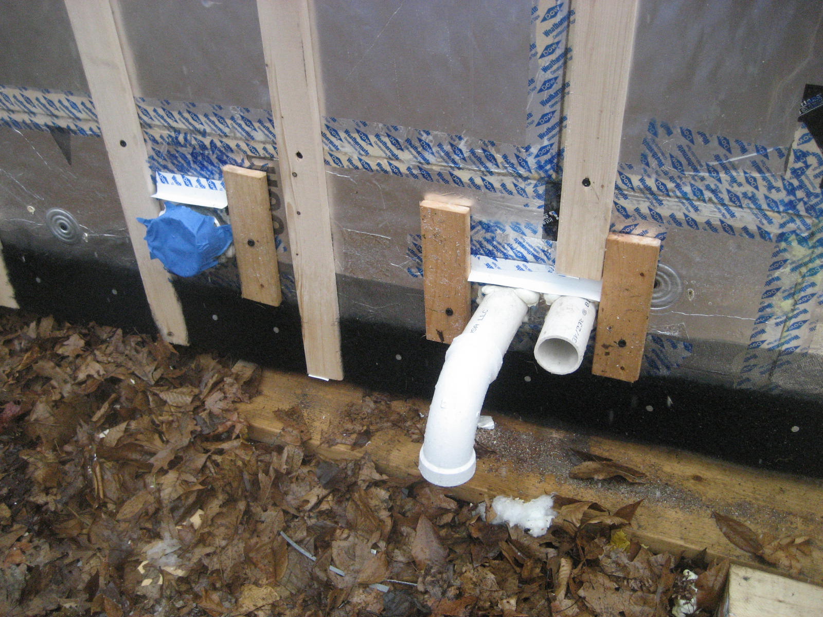
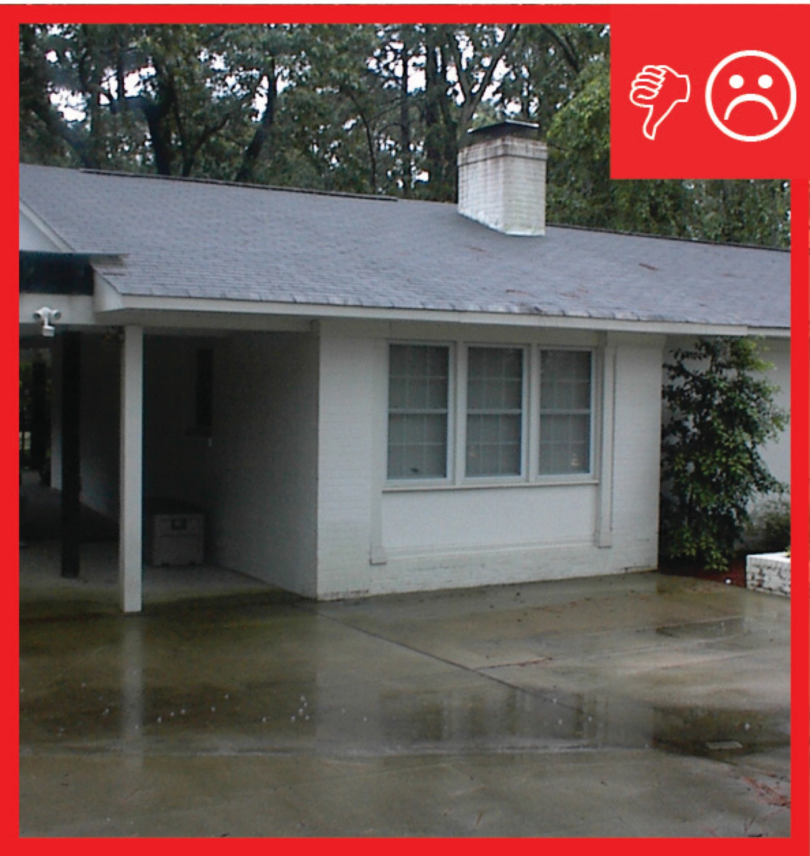
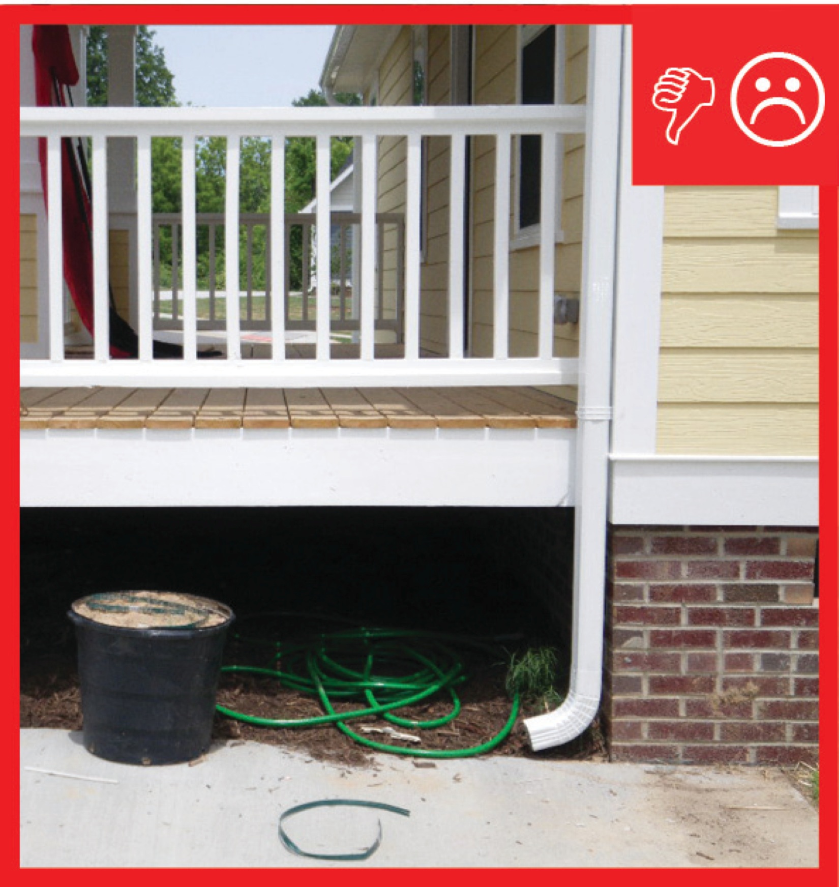
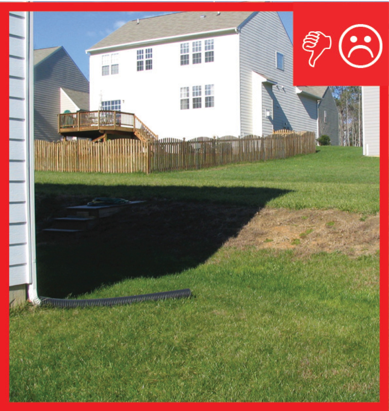
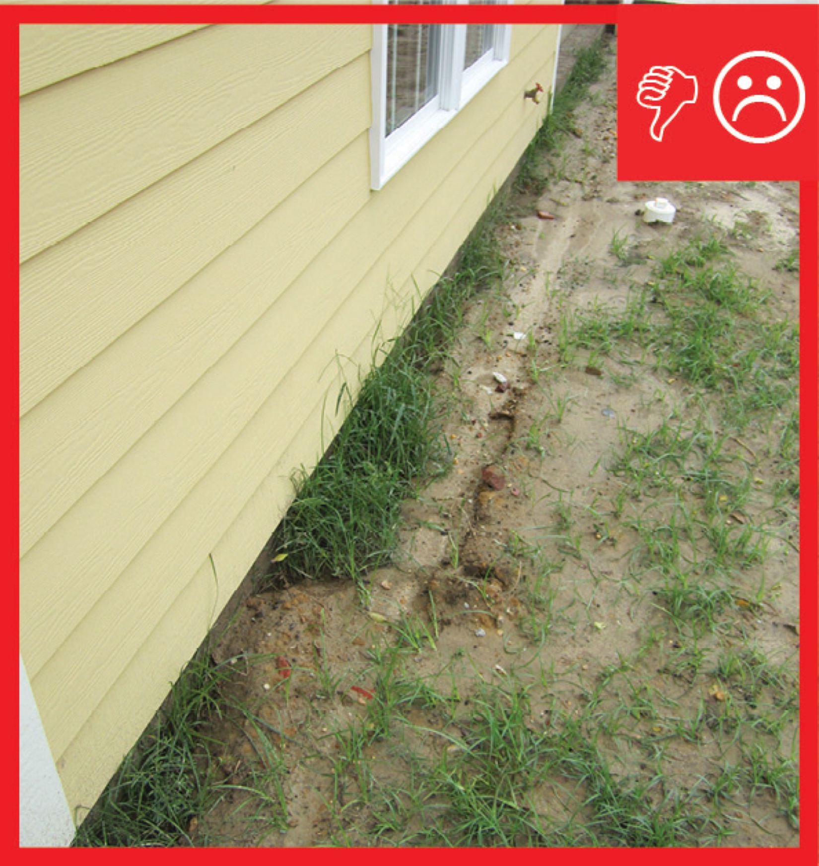
Wrong - This surface downspout run-out is directed toward the foundation instead of away from it.
Image
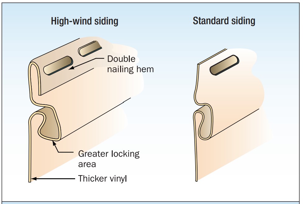
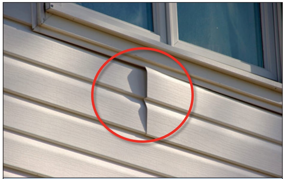
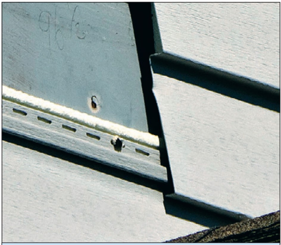
Wrong - Utility trim was substituted for the starter strip and the bottom lock was cut off this vinyl siding so the siding pulled loose under wind pressure.
Image
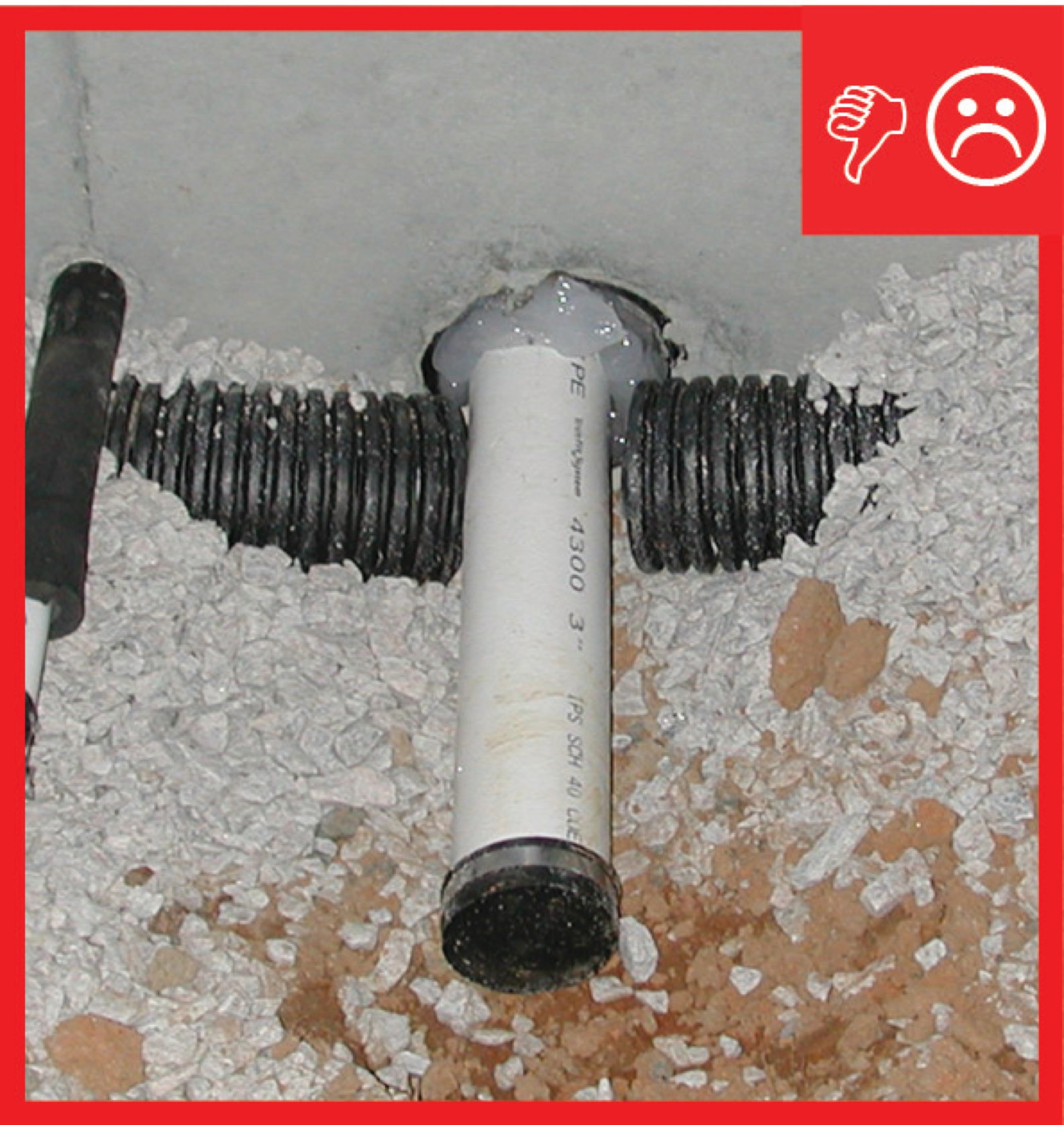
Wrong – Drain pipe has been cut and foundation penetration has not been properly sealed
Image
Image
Wrong – For proper detailing of vinyl around windows and other obstacles, use utility trim, punch snaplocks into siding, and do not overlap directly beneath a window.
Image
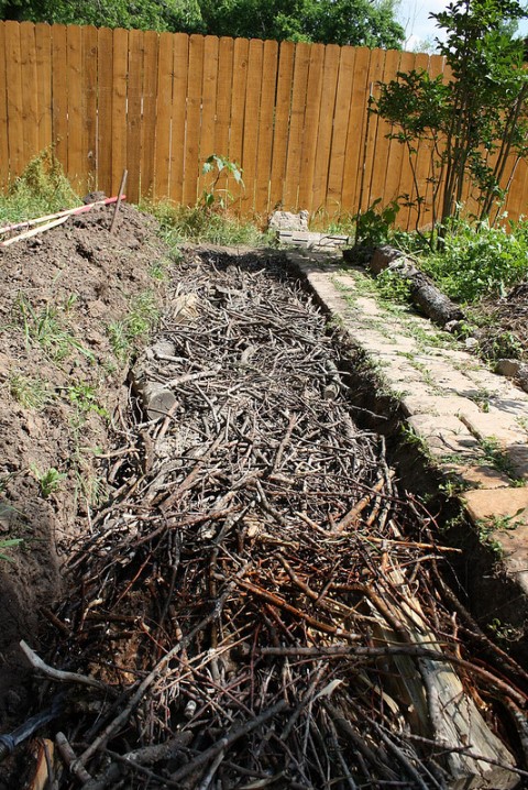
Wrong – Known as a Hugel Swale, organic matter like sticks and leaves break down into compost and fill the swale full. This limits the swale’s ability to filter rainwater.
Image
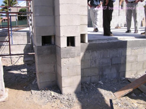
Wrong – Misalignment of the tie reduces the embedment and enables the brick veneer to be pulled away.
Image
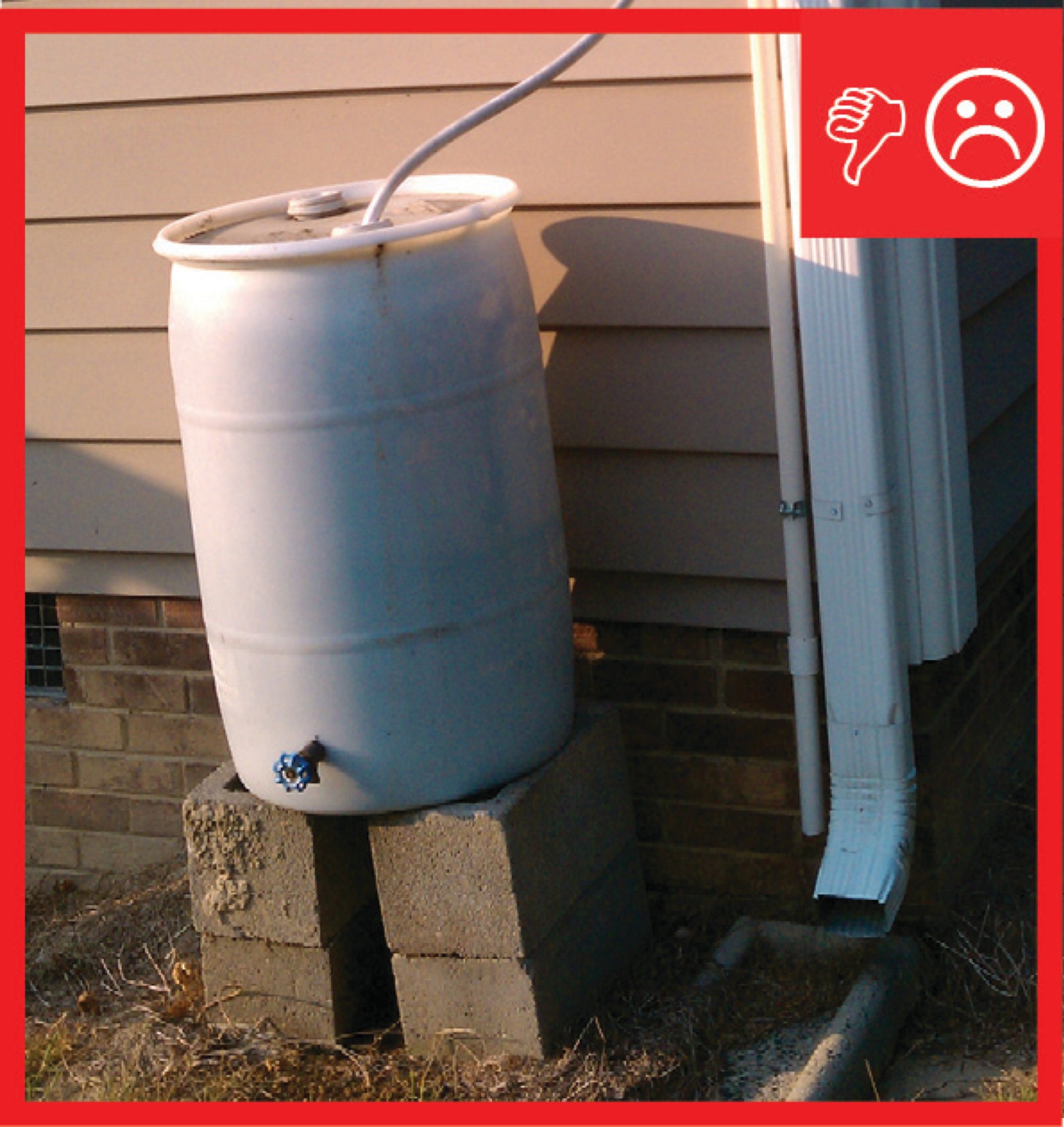
Wrong – Rain barrel installed without an overflow spout that terminates away from foundation
Image

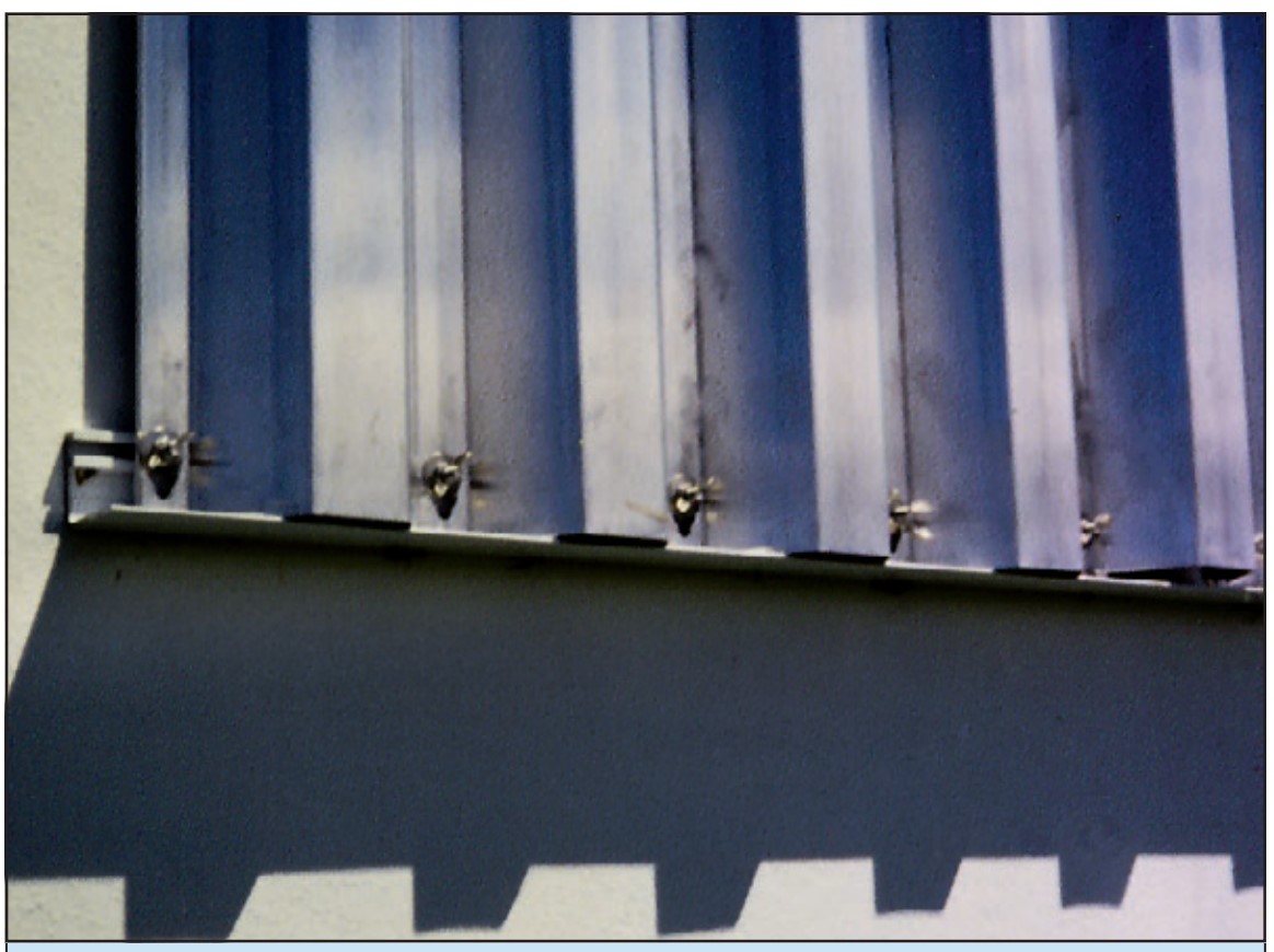
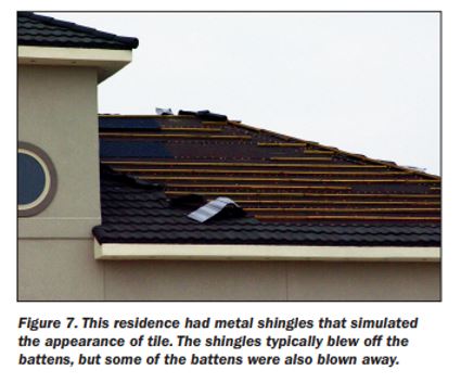
Wrong – The clips holding these metal roofing panels were set too far from the roof eave (above red line) and the panels lifted in strong winds
Image
Image
Image
Image
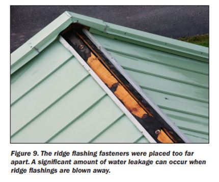
Wrong – The ridge flashing fasteners were placed too far apart and did not adequately hold the flashing in place
Image
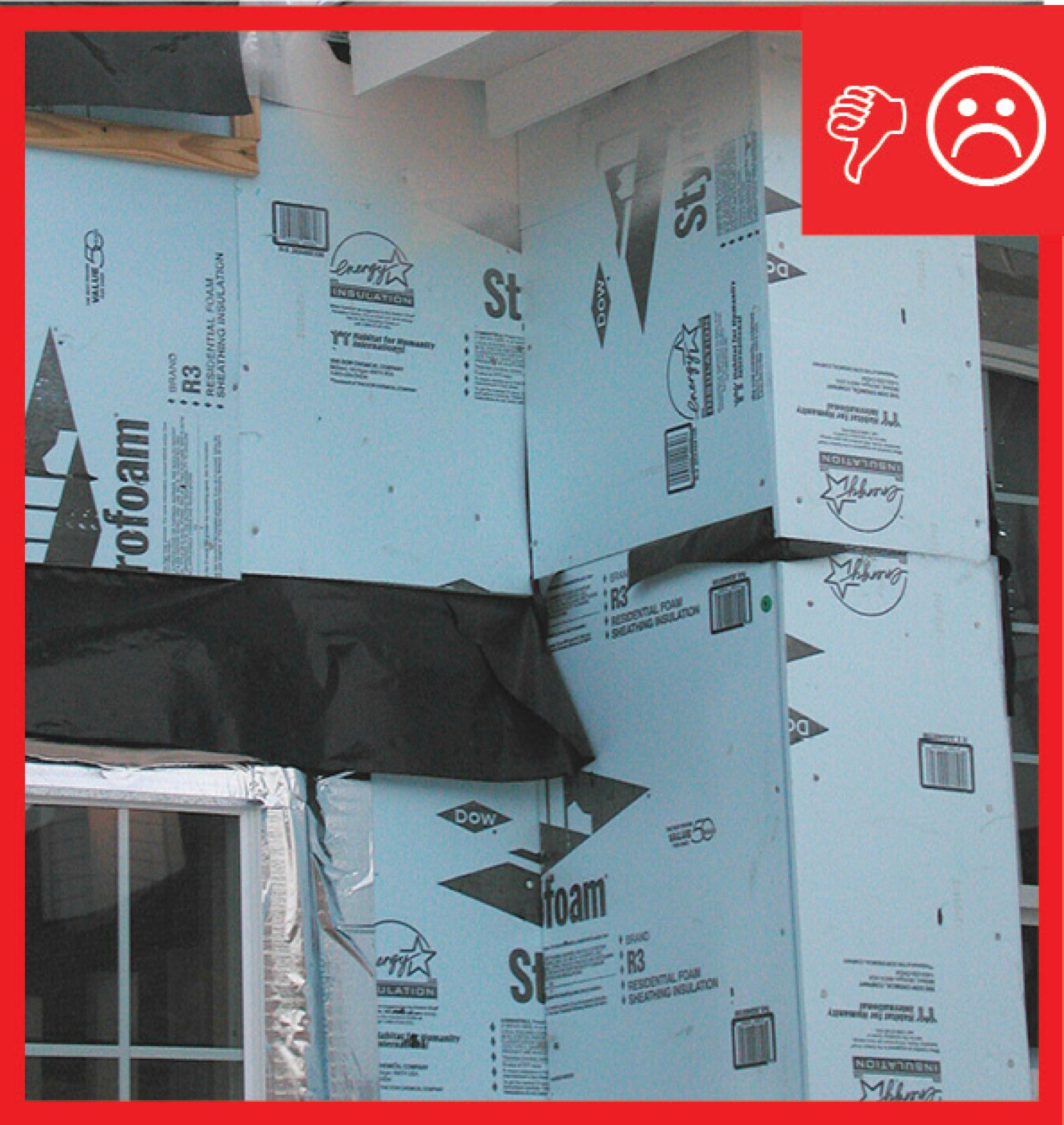
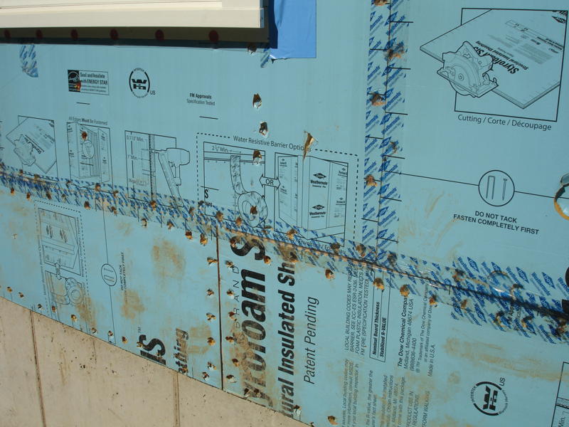
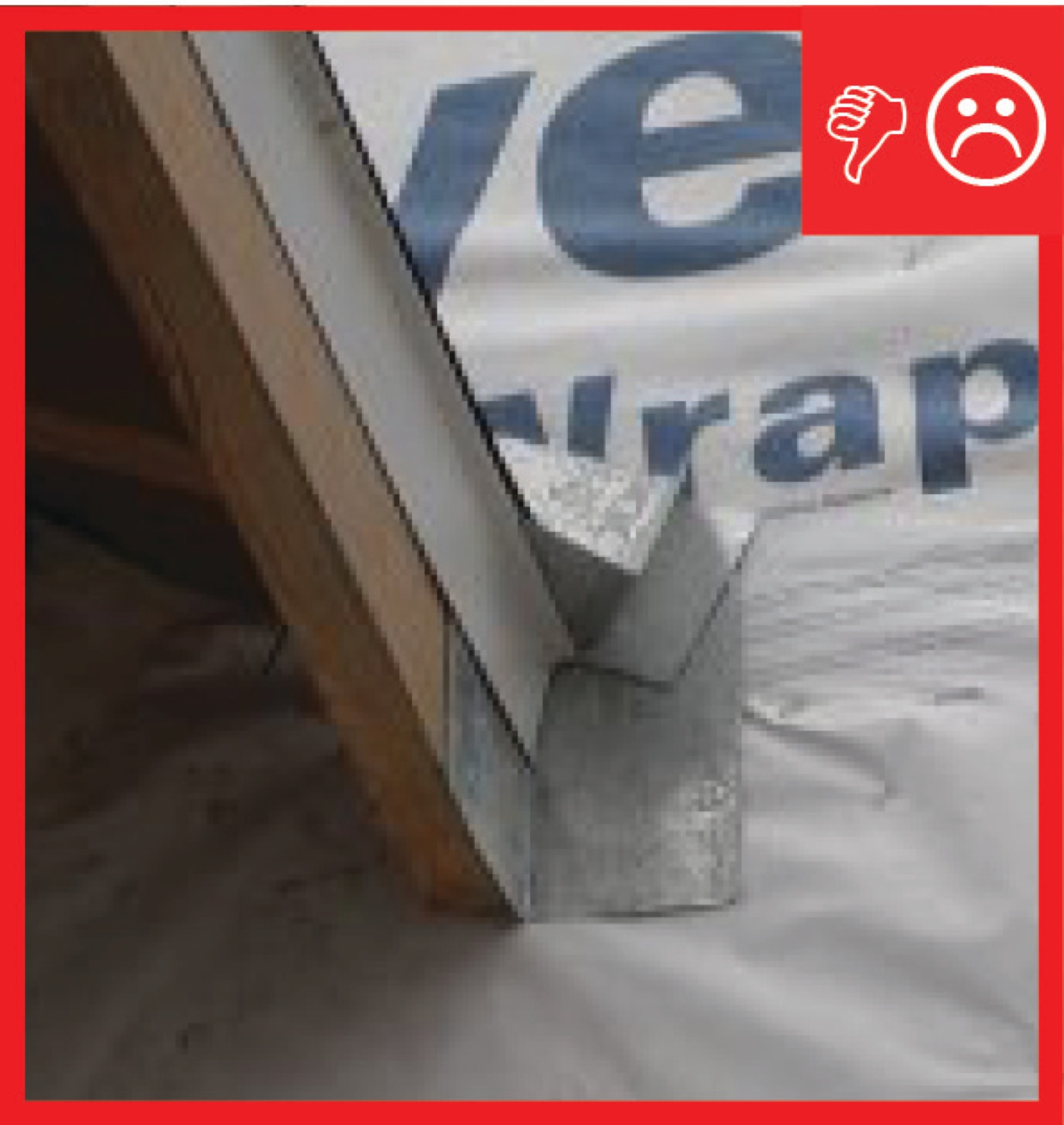
Wrong – The rigid sheathing seams are not taped and the gaps could cause moisture problems
Image
Image
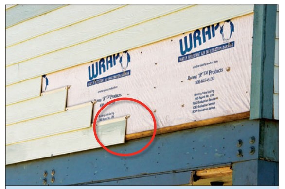
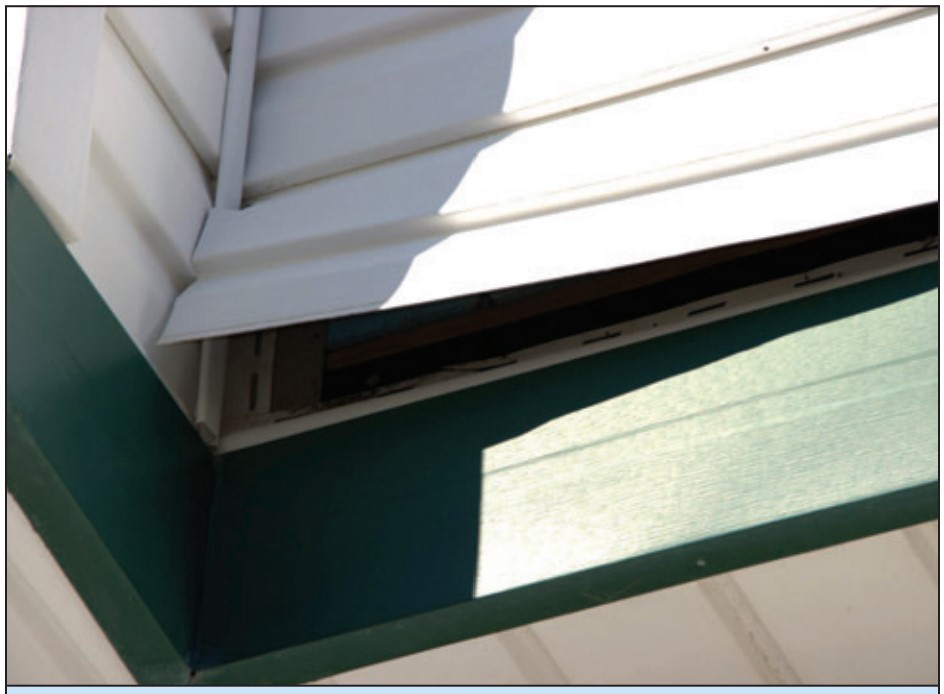
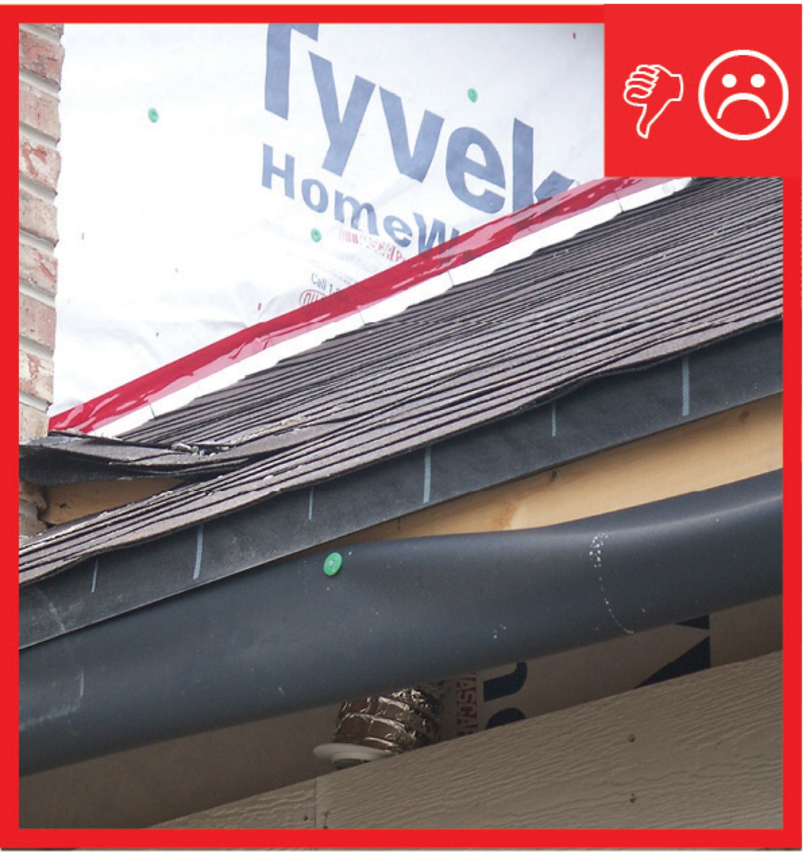
Wrong – The underside of the first course of siding extends beyond the underlying sheathing leaving it vulnerable being pulled off by pressure from high winds.
Image
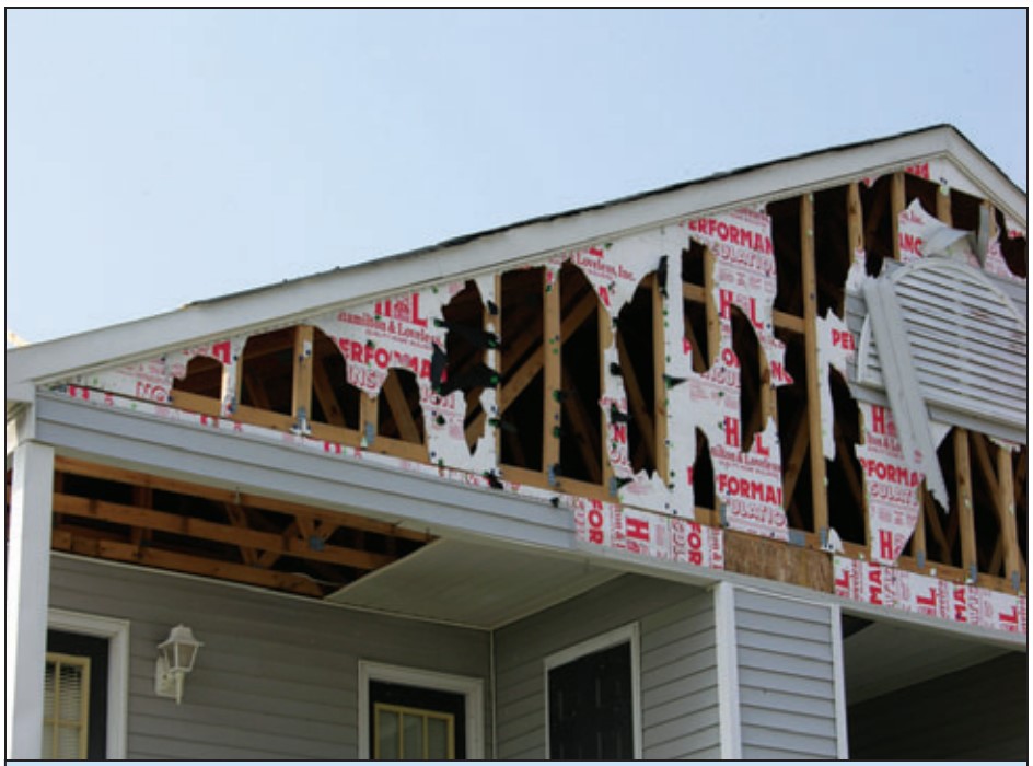
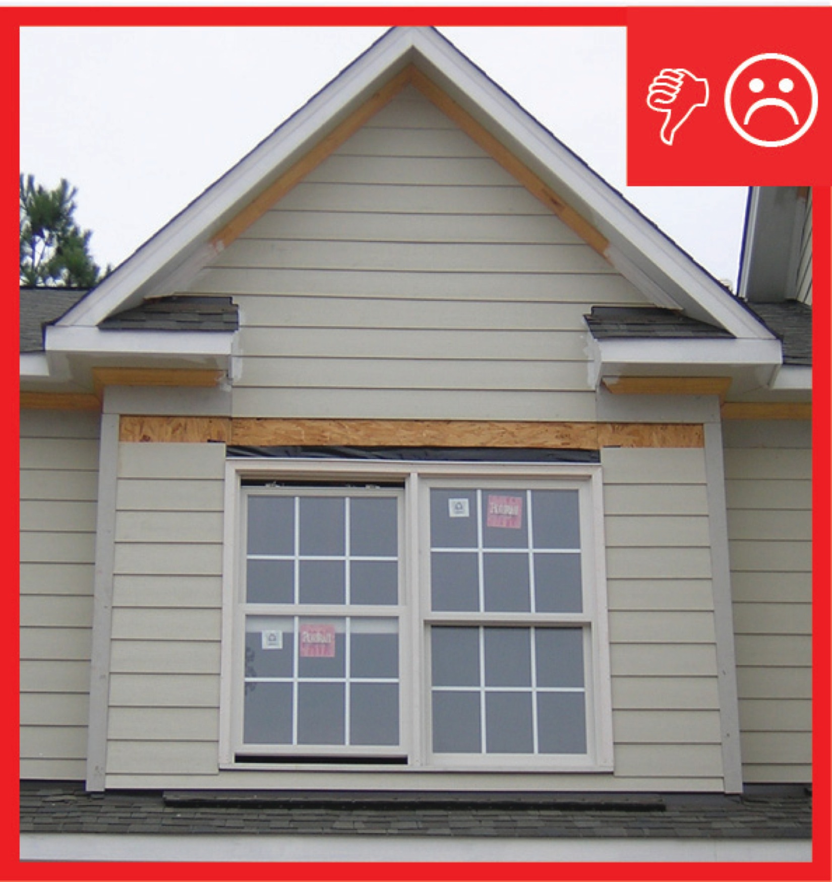
Wrong – The vinyl siding at this gable was installed over rigid foam instead of wood sheathing and neither had the structural strength to resist hurricane wind pressures.
Image
Image
Wrong – the water-resistant barrier is layered underneath the step flashing, which could allow water to get behind the step flashing and into the wall.
Image
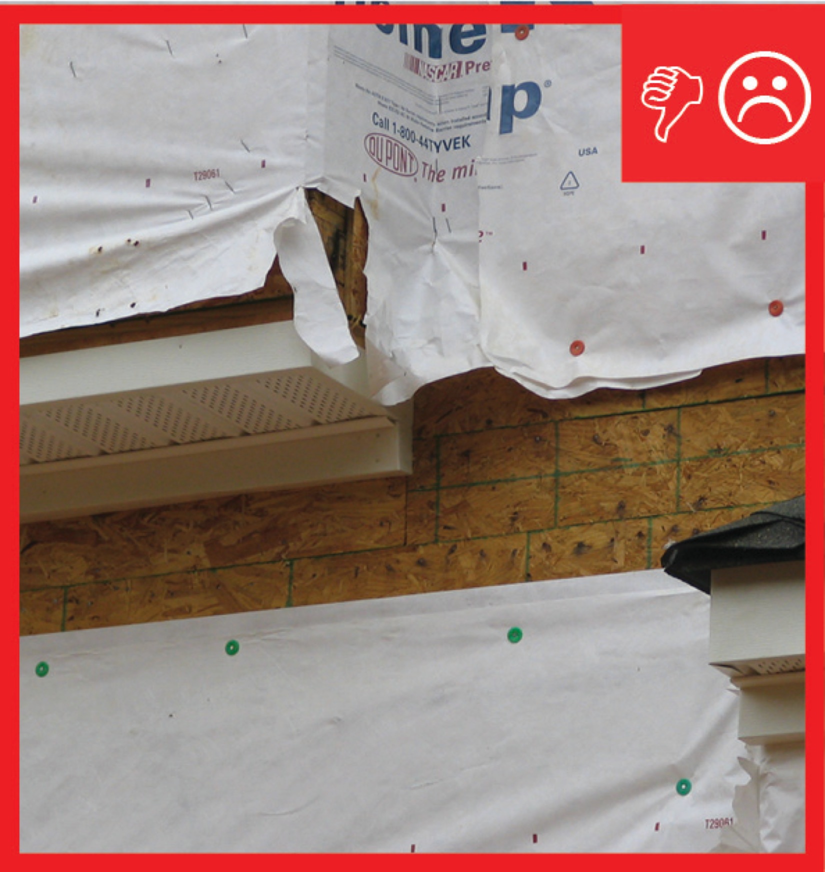
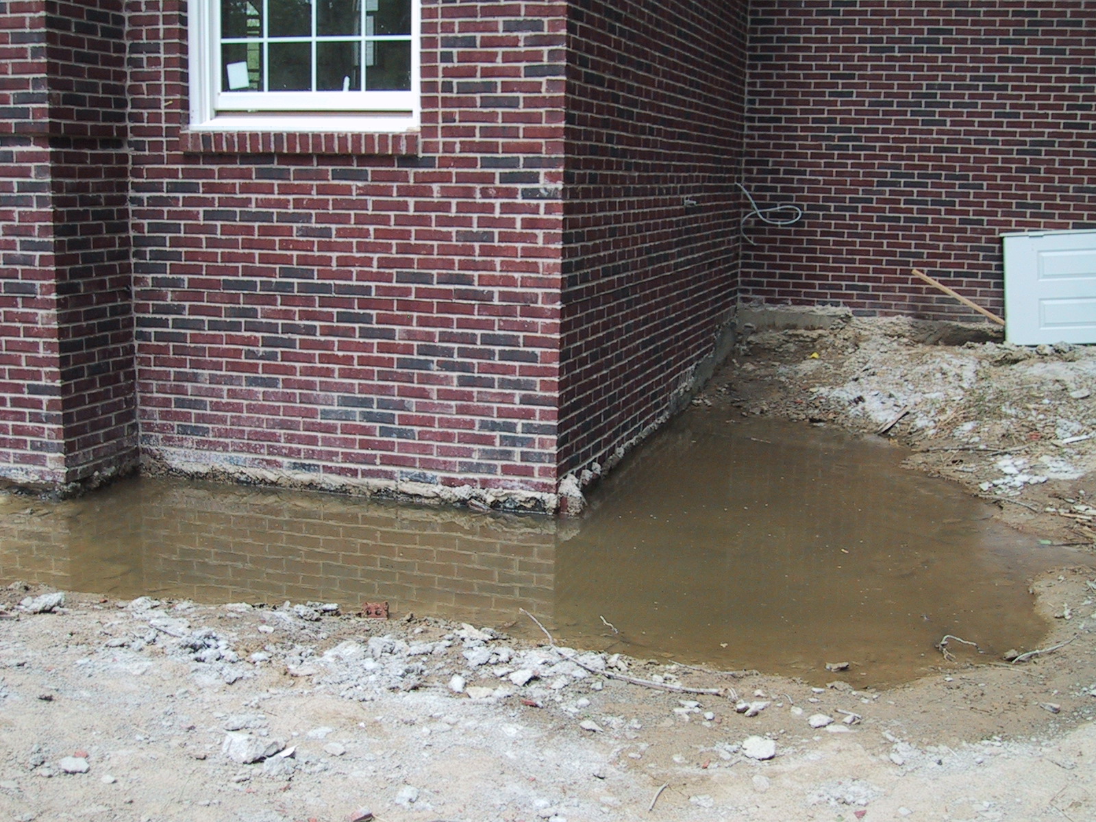
Wrong – The water-resistant barrier is not complete and the holes and gaps could cause moisture problems
Image
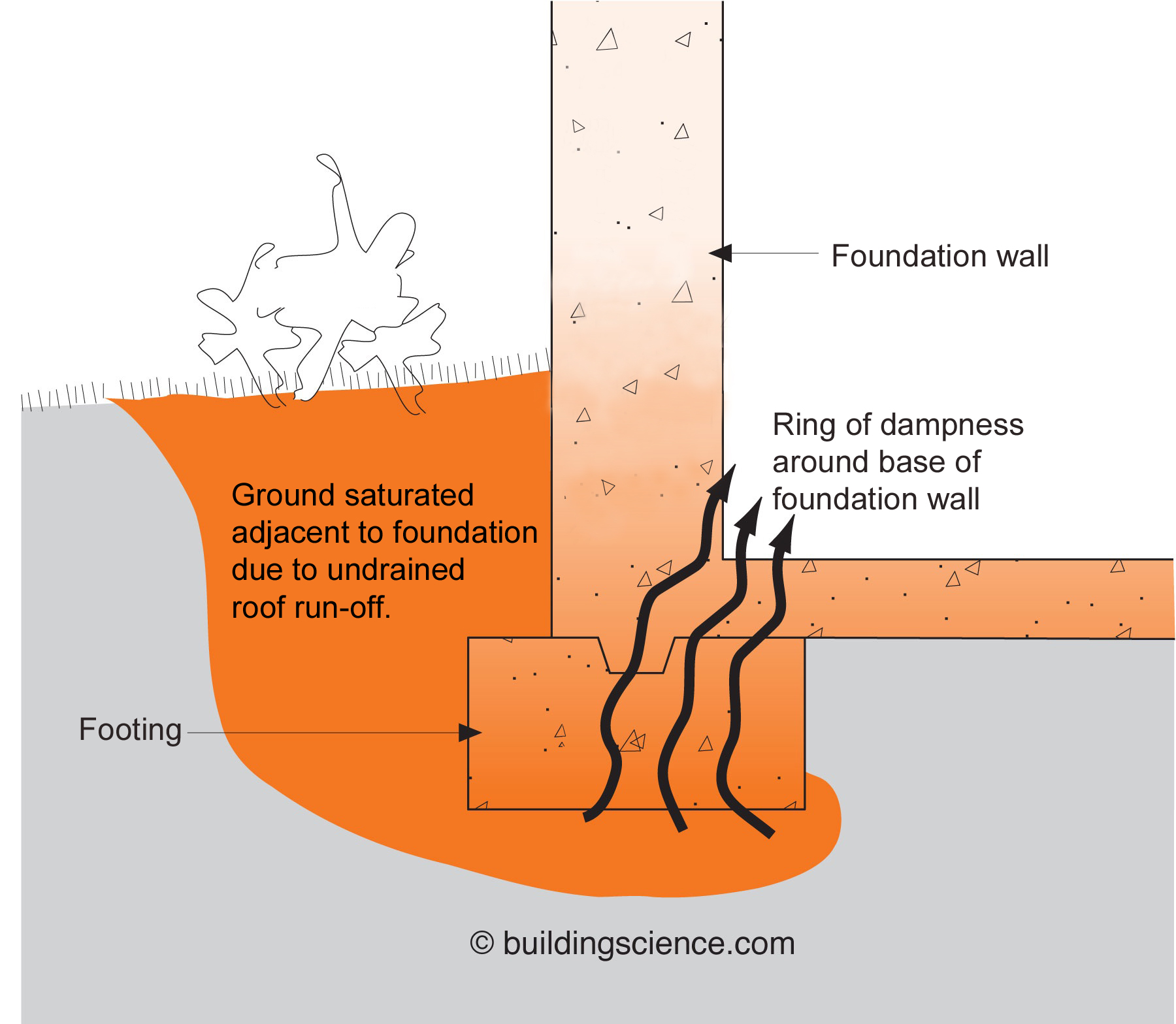
Wrong – There are no gutters installed and there is not a proper gravel bed located at the foundation
Image
Wrong – There is not a self-sealing bituminous membrane installed at the valley of the roof
Image
Wrong – There is not a water-resistant barrier installed underneath the exterior finish of the walls
Image
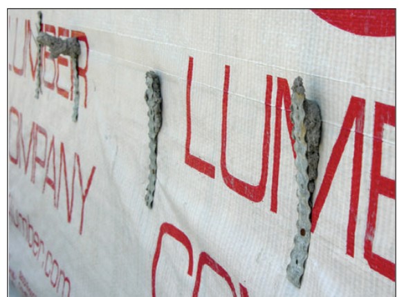
Wrong – These four ties were never embedded into the mortar joint, allowing the brick wall to be pulled away from the sheathing.
Image
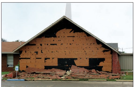
Wrong – This brick veneer failed in high winds (107 mph) because the ties pulled out of the substrate.
Image
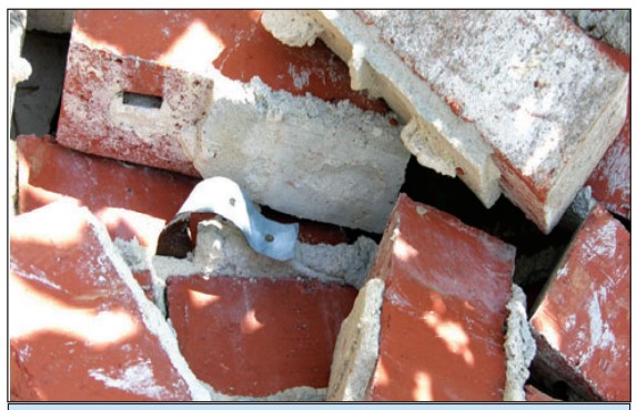
Wrong – This metal tie remained embedded in the mortar joint but the smooth-shank nail pulled out from the stud.
Image
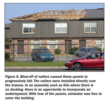
Wrong – This roof has no sheathing, when the metal panels blew off there was no secondary protection
Image
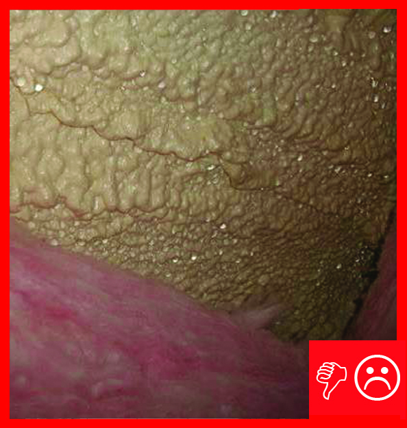
Wrong: Closed-cell spray foam roof insulation was not thick enough to meet IRC levels so the foam surface is colder than the dew point of the interior air and condensation formed on surface of the foam