Showing results 1 - 250 of 256
Image
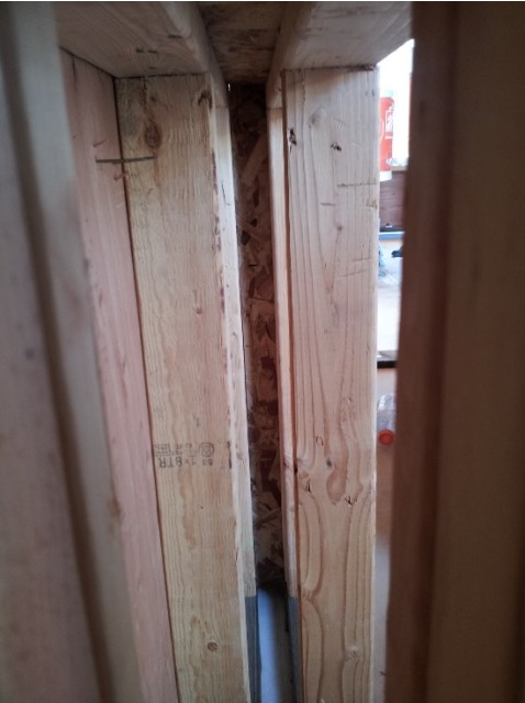
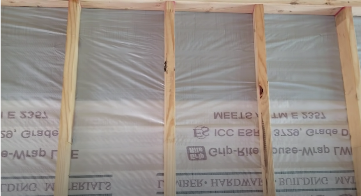
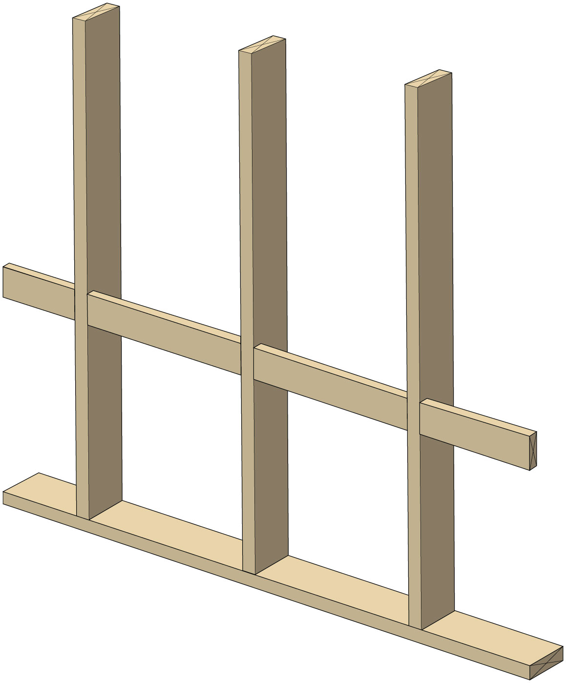
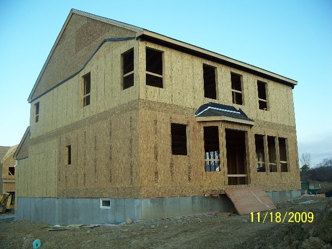
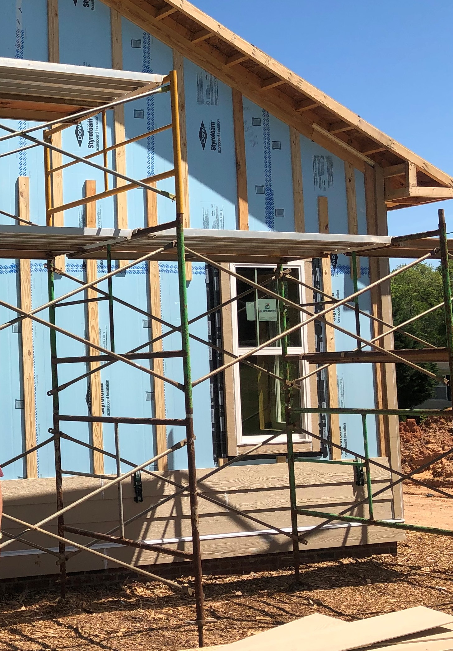
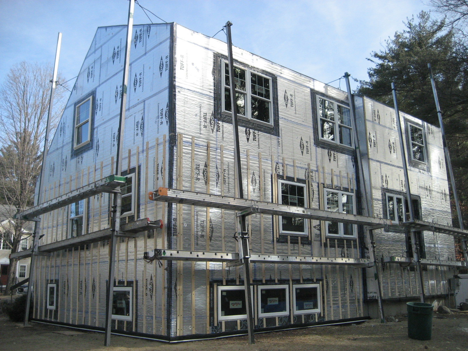
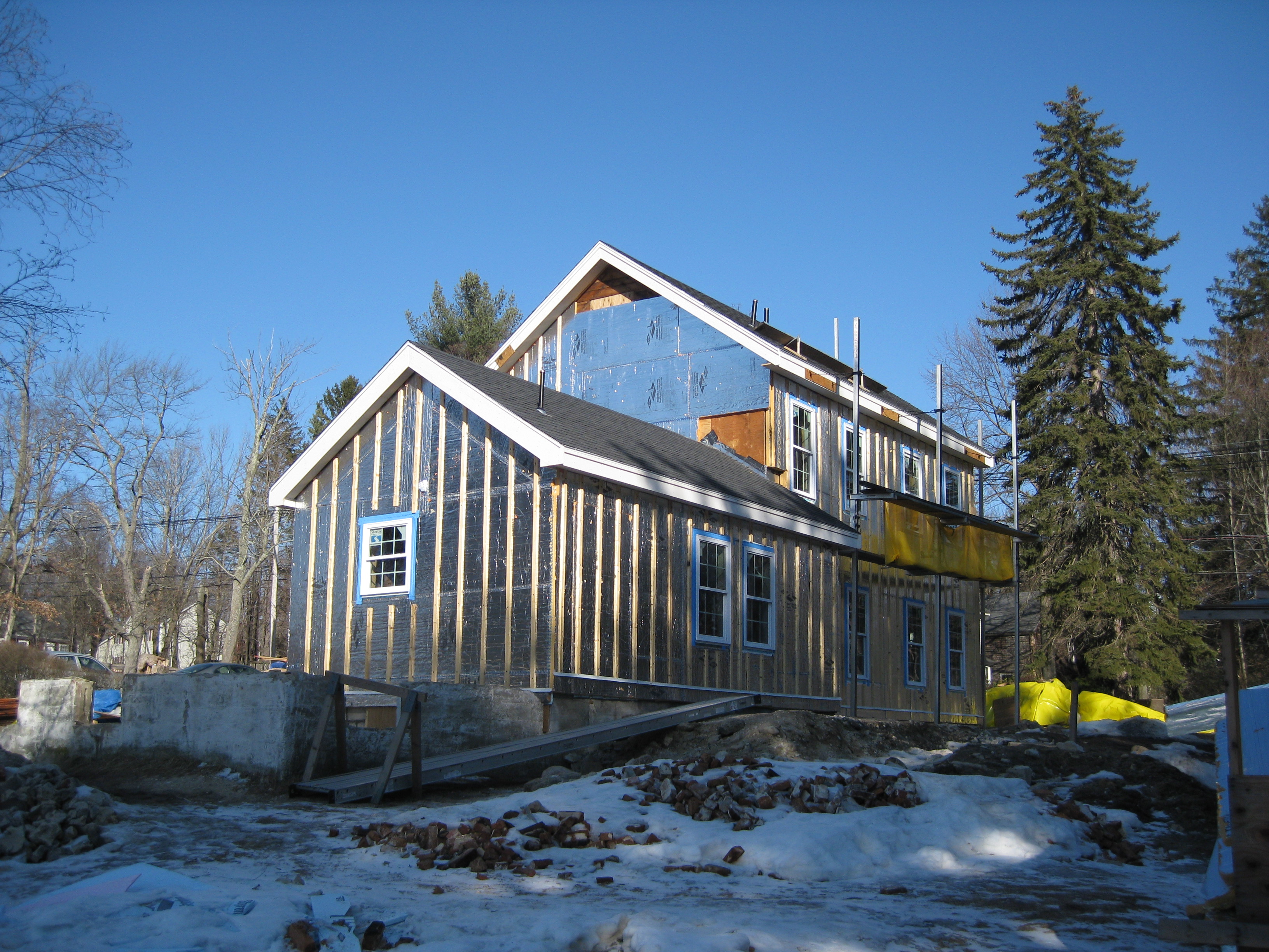
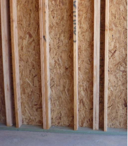
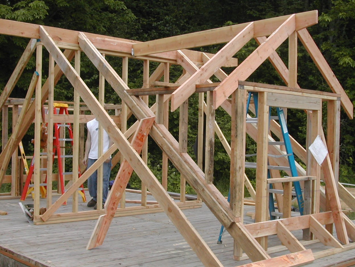
Example of the advanced framing technique, double-stud wall cavity, which will later be filled with blown insulation
Image
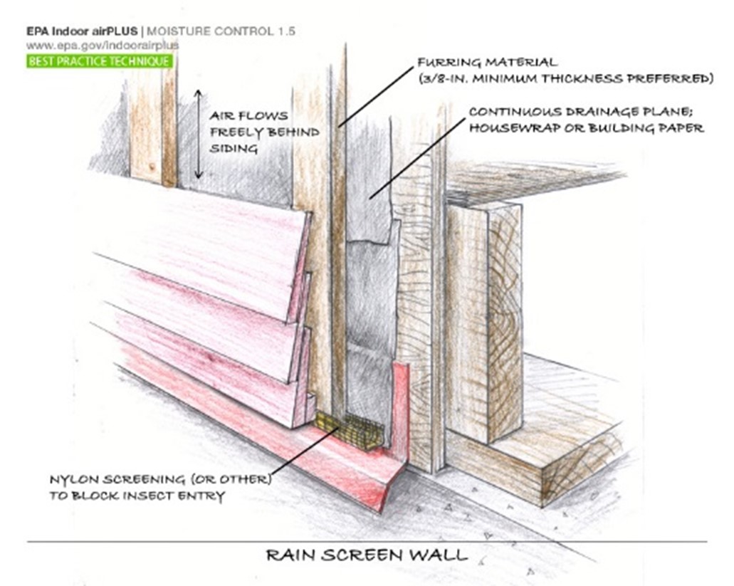
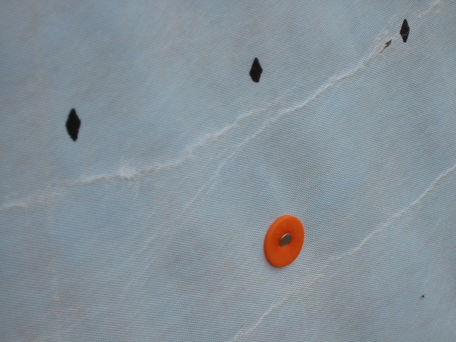
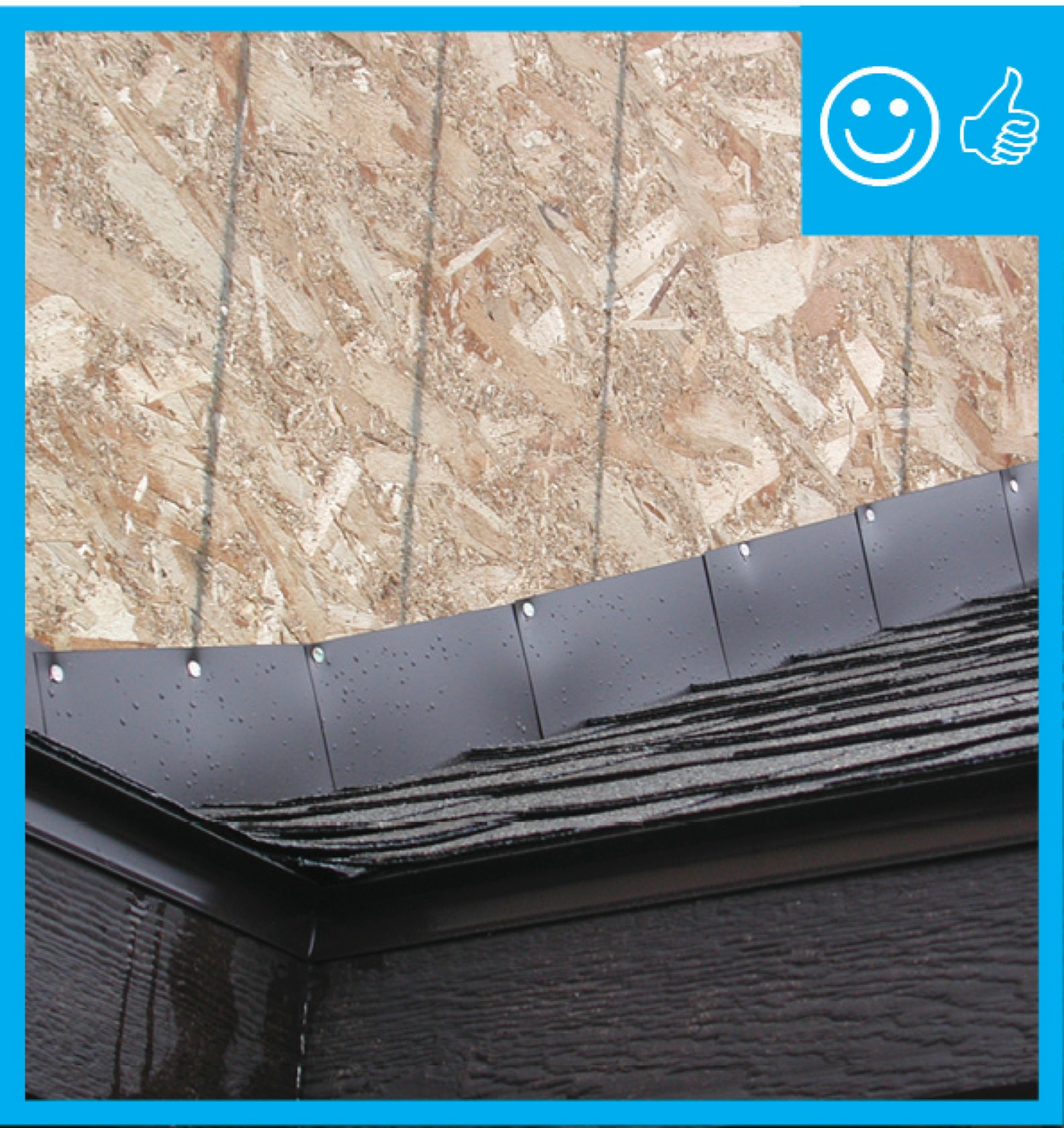
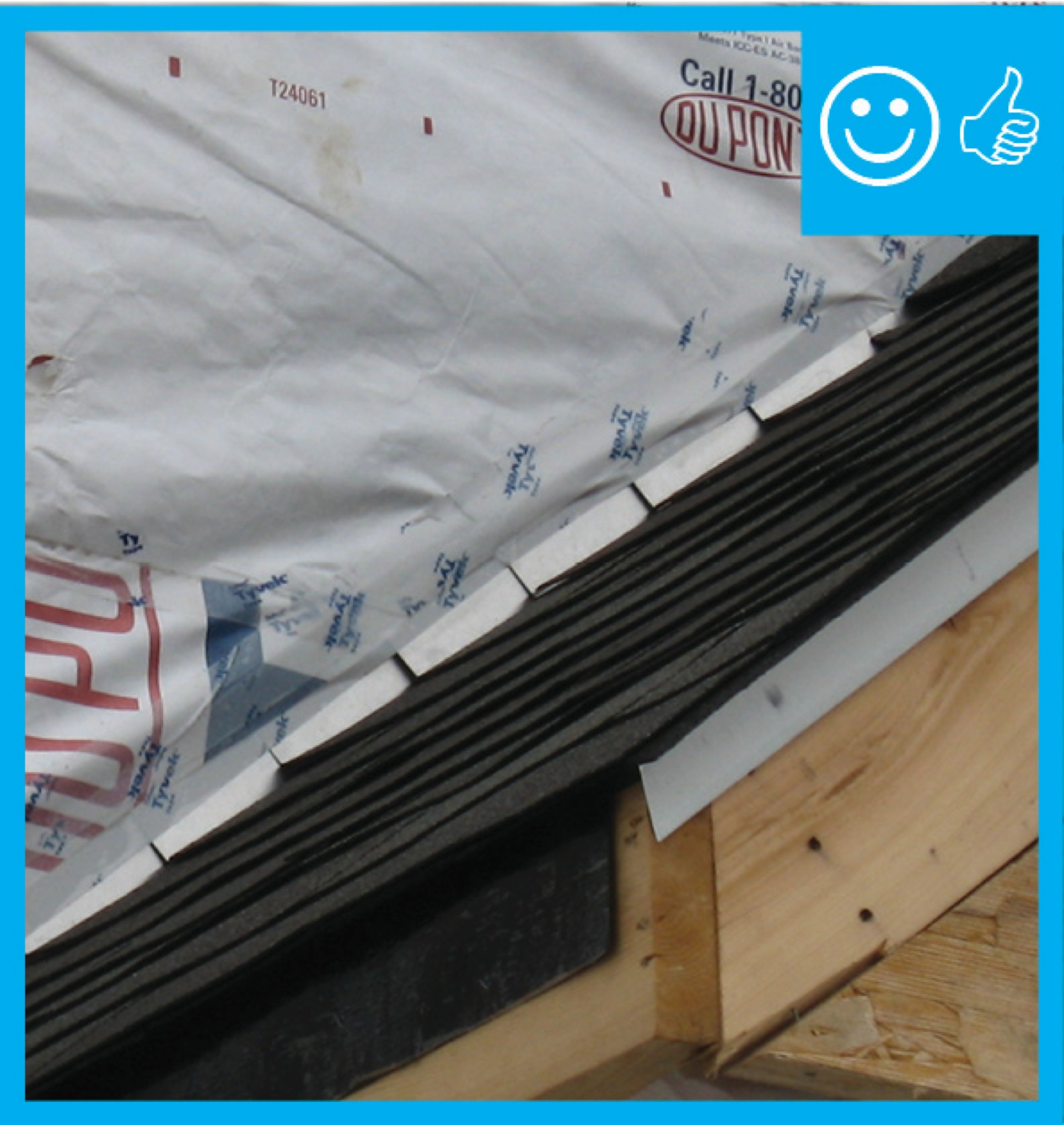
Install mesh insect barrier along the bottom of the rain screen behind the exterior cladding of above-grade walls
Image
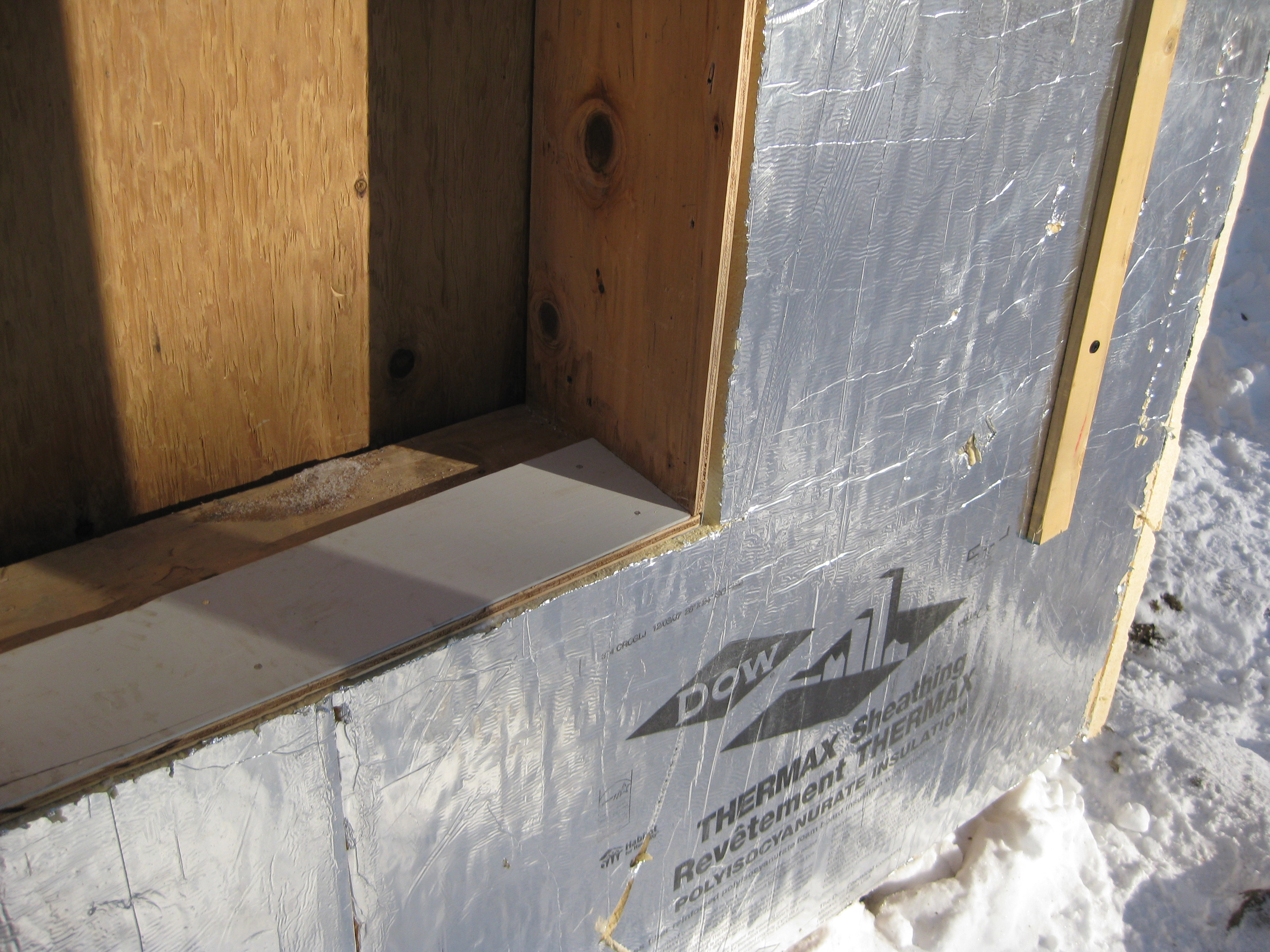
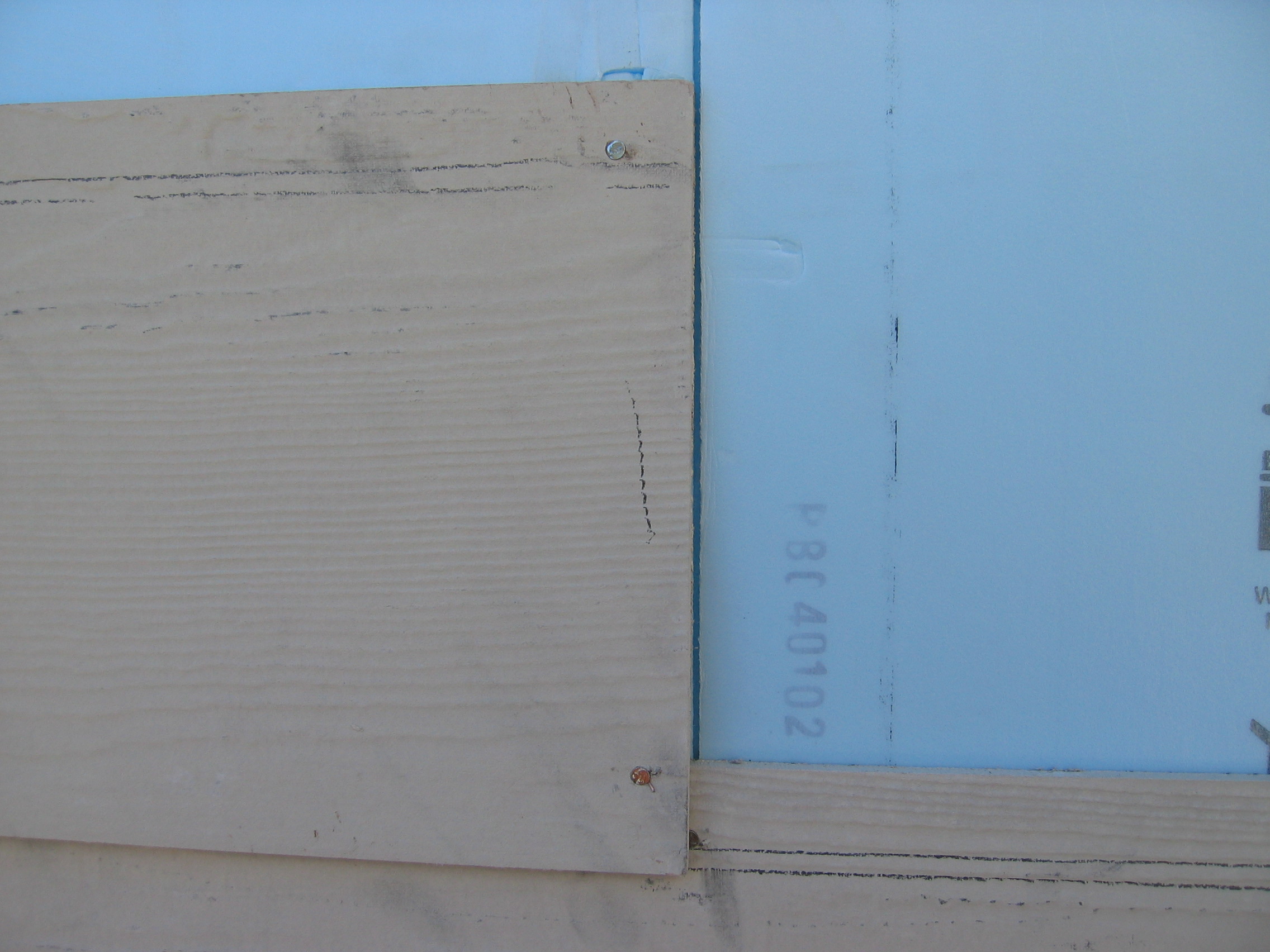
A piece of siding is used as sill extension and to provide slope in the opening for the window, which is deeper because exterior rigid foam has been added
Image
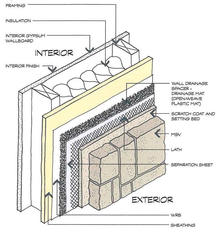
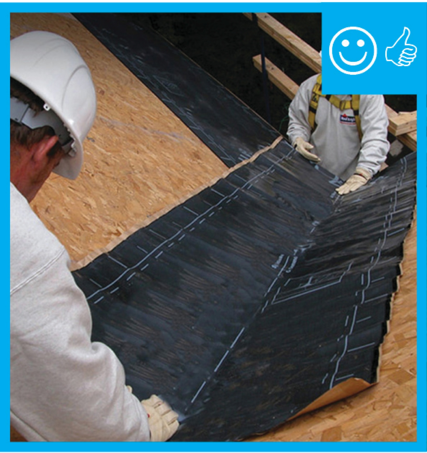
A plastic fiber drainage mat rainscreen provides uniform support for the siding and allows moisture to flow horizontally and diagonally in addition to vertically.
Image
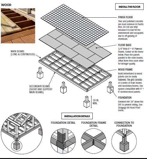
A raised wood pier foundation can raise the subfloor above the design flood elevation.
Image
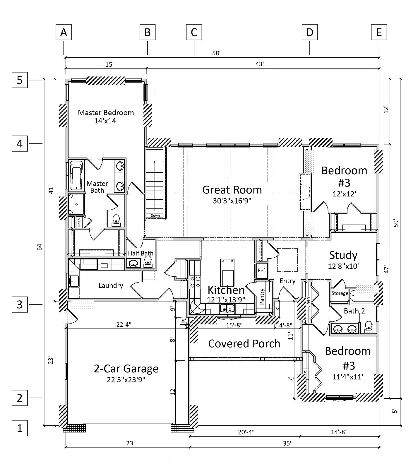
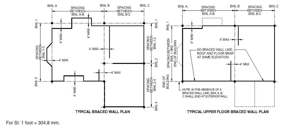
A single-story house floor plan showing braced wall line locations at A through E and 1 through 5
Image
A typical Las Vegas hot-dry climate home made of wood frame construction and insulated with R-25 expanded polystyrene externally over a drainage plane, with an unvented wood frame insulated attic and roof assembly.
Image
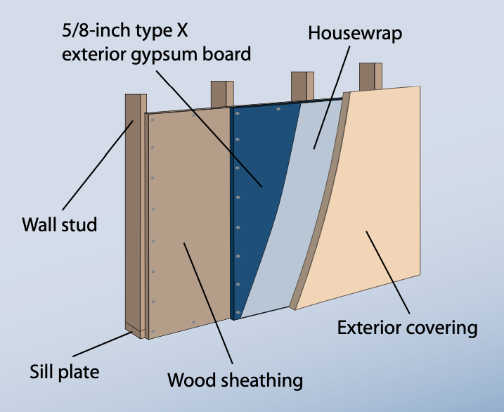
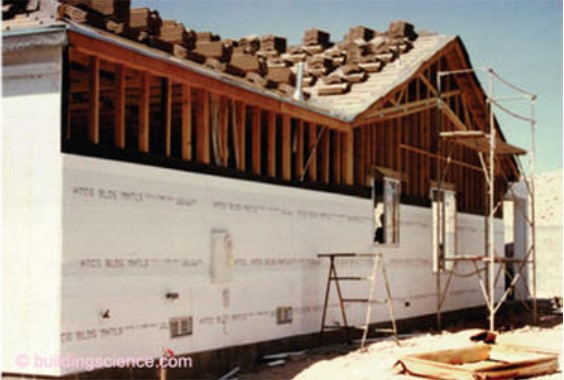
A wall assembly approved for use in the wildland-urban interface has 5/8-inch type X gypsum installed exterior of the wood sheathing and an exterior covering or siding that has a 1-hour fire-resistance rating
Image
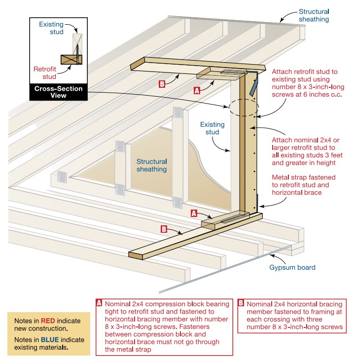
Add metal connectors to strengthen framing connections in an existing wall from inside the home by removing drywall.
Image

Image
Image
Image
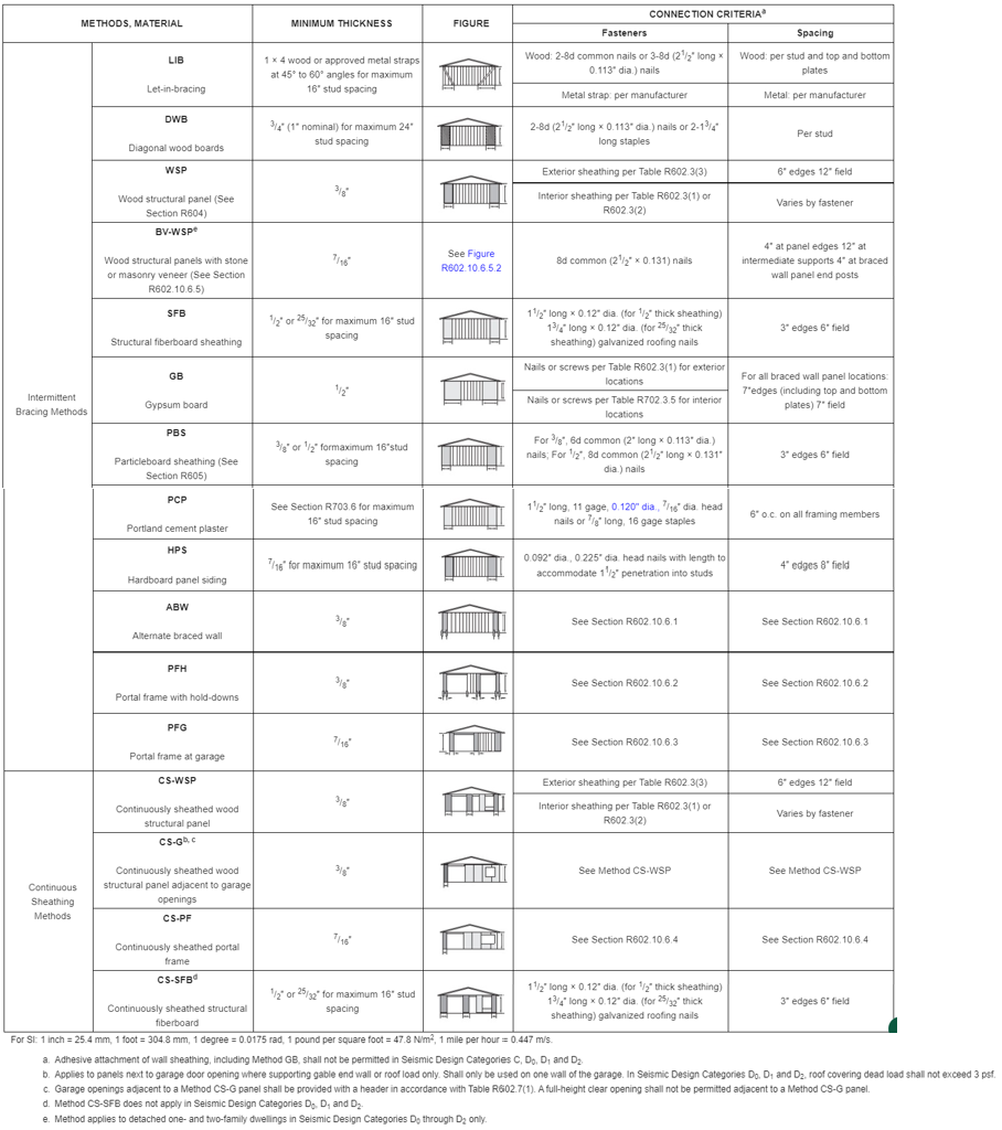
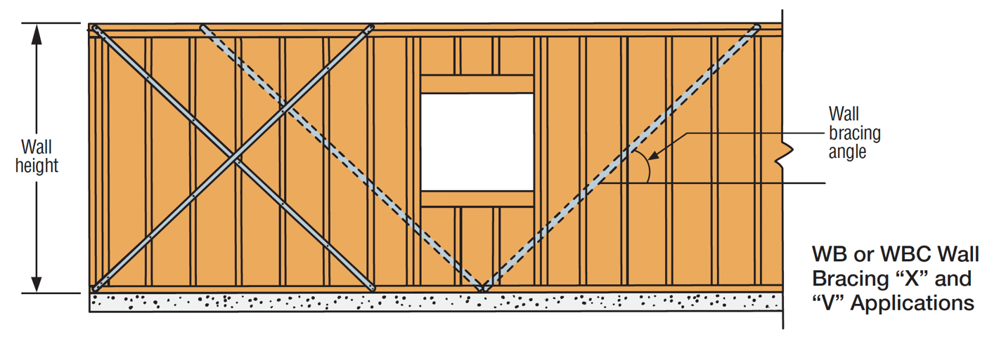
An exterior wall braced using the let-in-bracing (LIB) method with no exterior sheathing
Image
Image
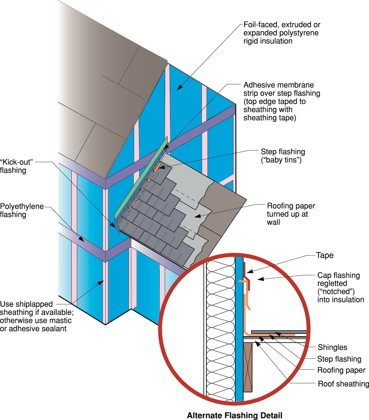
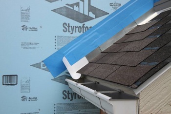
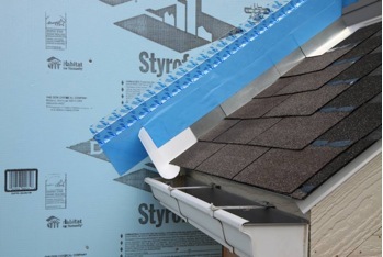
Apply self-adhesive flashing over top edge of the wall flashing, diverter, and housewrap
Image

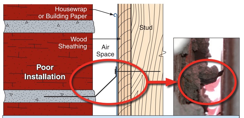
Bees made a nest in the drainage plane behind a brick veneer wall by entering via unscreened weep holes
Image
Image
Image
Brick veneer framed wall supported by a concrete slab-on-grade foundation with a turn-down footing insulated on its top surface, showing anchorage of the wall to the foundation for seismic resistance
Image
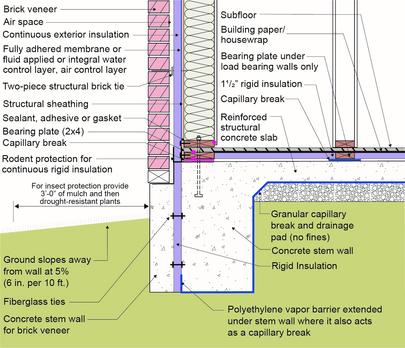
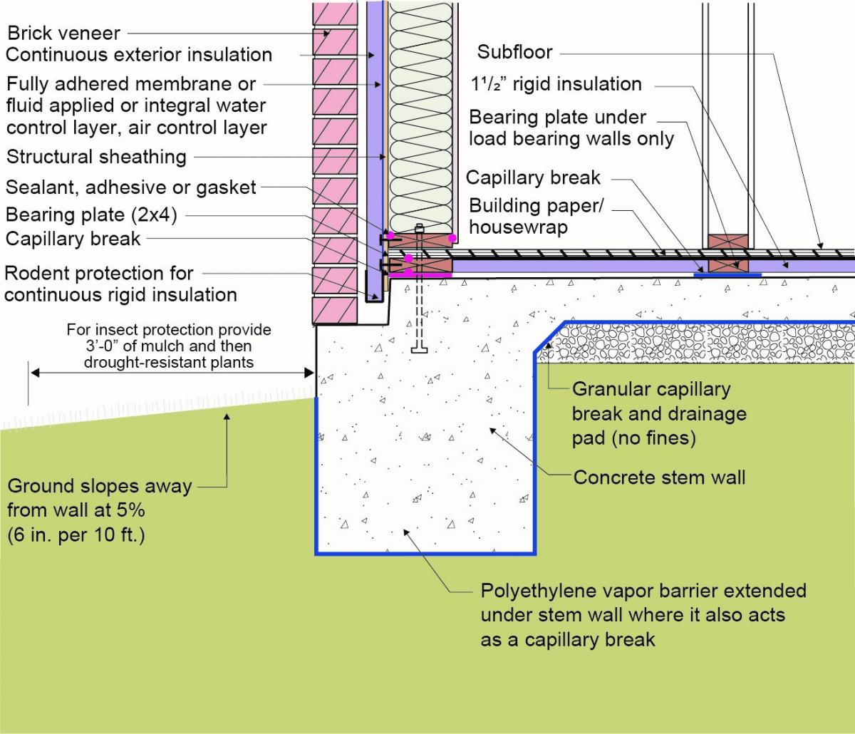
Brick veneer is supported by a concrete stem wall thermally separated from the slab-on-grade foundation with turn-down footing which is also insulated on top; anchorage for seismic resistance is also shown
Image
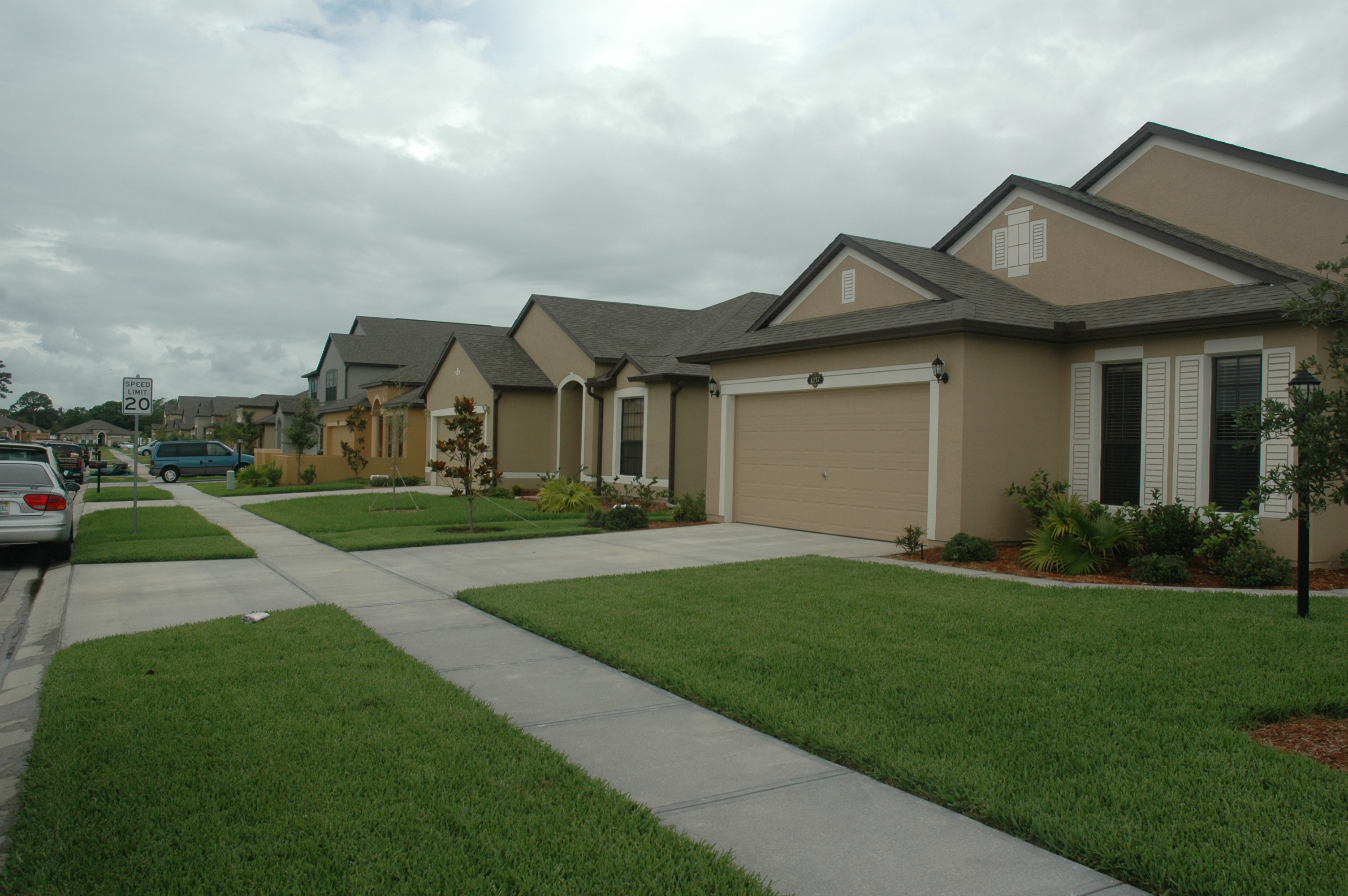
Building America worked with Mercedes Homes in east Florida to design homes using cast-in-place concrete walls capable of withstanding wind-blown debris impacts of up to 200 mph (Source: Mercedes Homes).
Image
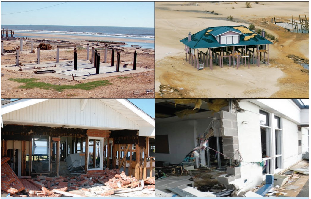
Buildings damaged by a hurricane storm surge: upper homes on gulf shoreline were hit by large waves above the lowest floor, lower left home on bay and right school 1.3 miles from gulf shoreline were hit by surge and small waves.
Image
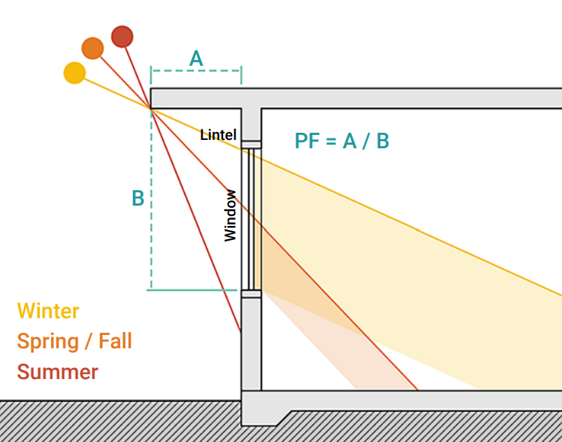
Calculate projection factor (PF) by dividing overhang (A) by length of window (B).
Image
Image
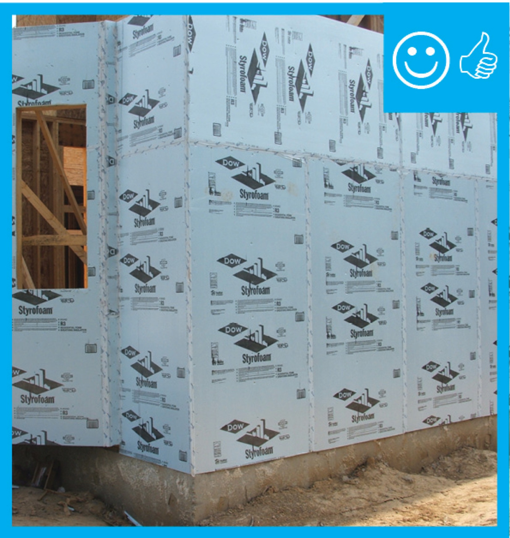
Clean taping areas and install 3" tape on vertical joint of upper insulation overlapping the horizontal joint
Image
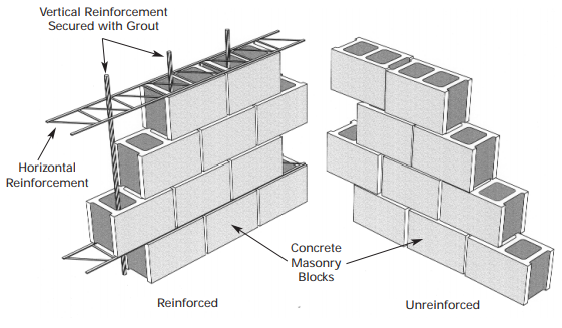
CMU construction can be reinforced with vertical rebar and horizontal steel reinforcement (left) or unreinforced (right), depending on structural requirements
Image
Concrete slab-on-grade foundation with a turn-down footing insulated on its top surface, showing anchorage of the wall to the foundation for seismic resistance
Image
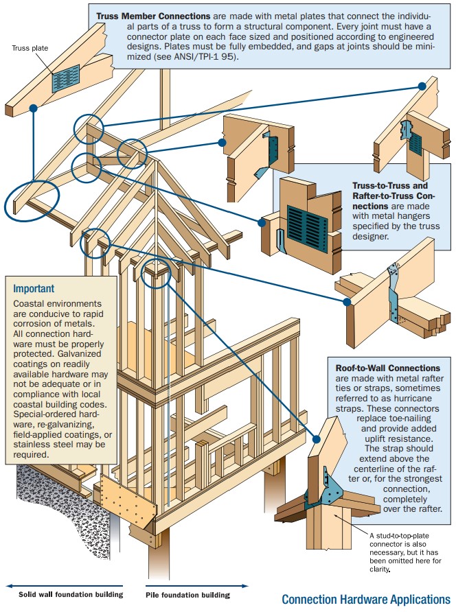
Connecting hardware helps tie the roof to the walls to ensure a continuous load path to improve a building’s resistance to high winds, floods, and earthquakes.
Image
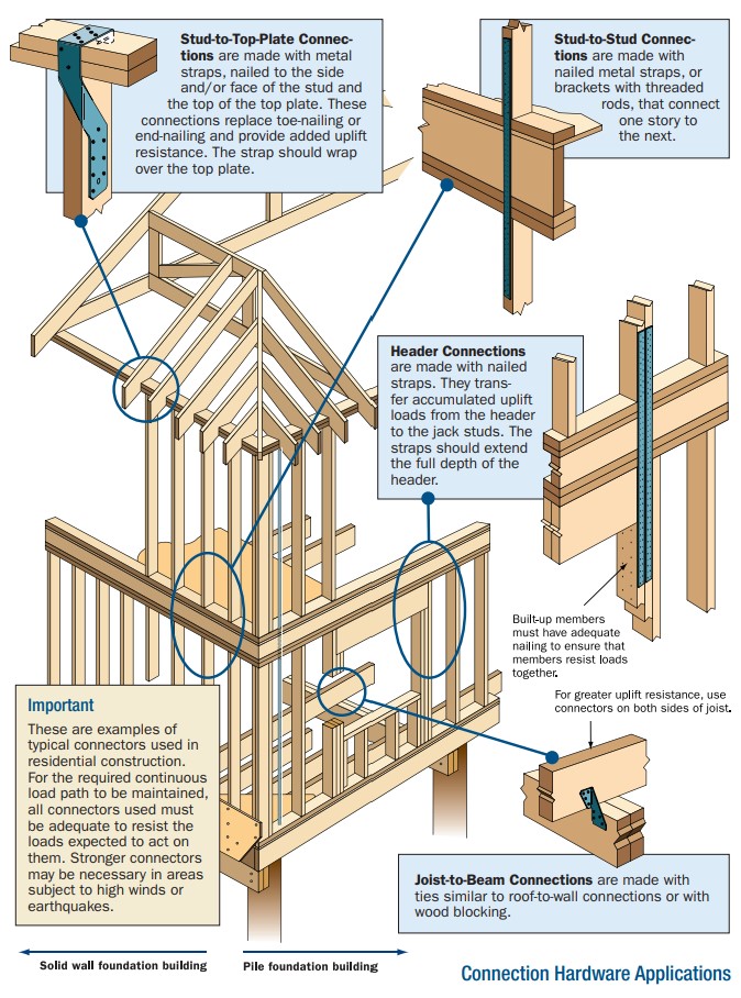
Connecting hardware helps tie the walls to the top plates and rim joists to ensure a continuous load path to improve a building’s resistance to high winds, floods, and earthquakes.
Image
Image
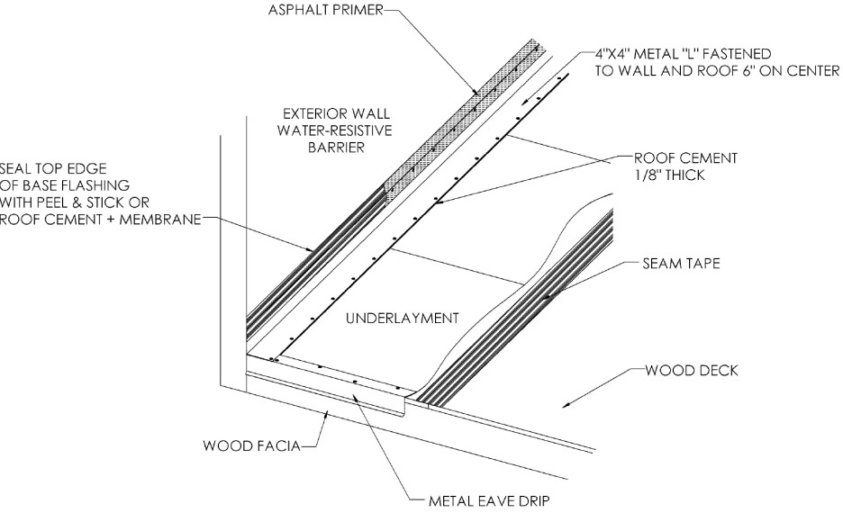
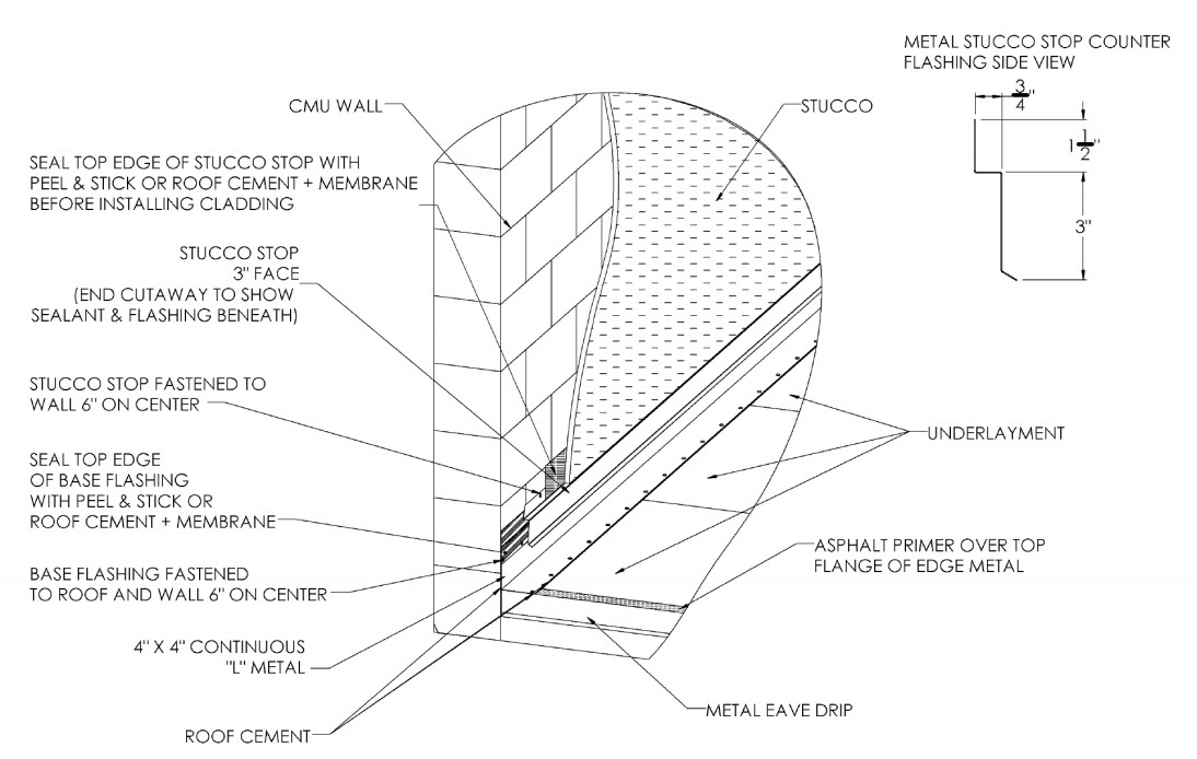
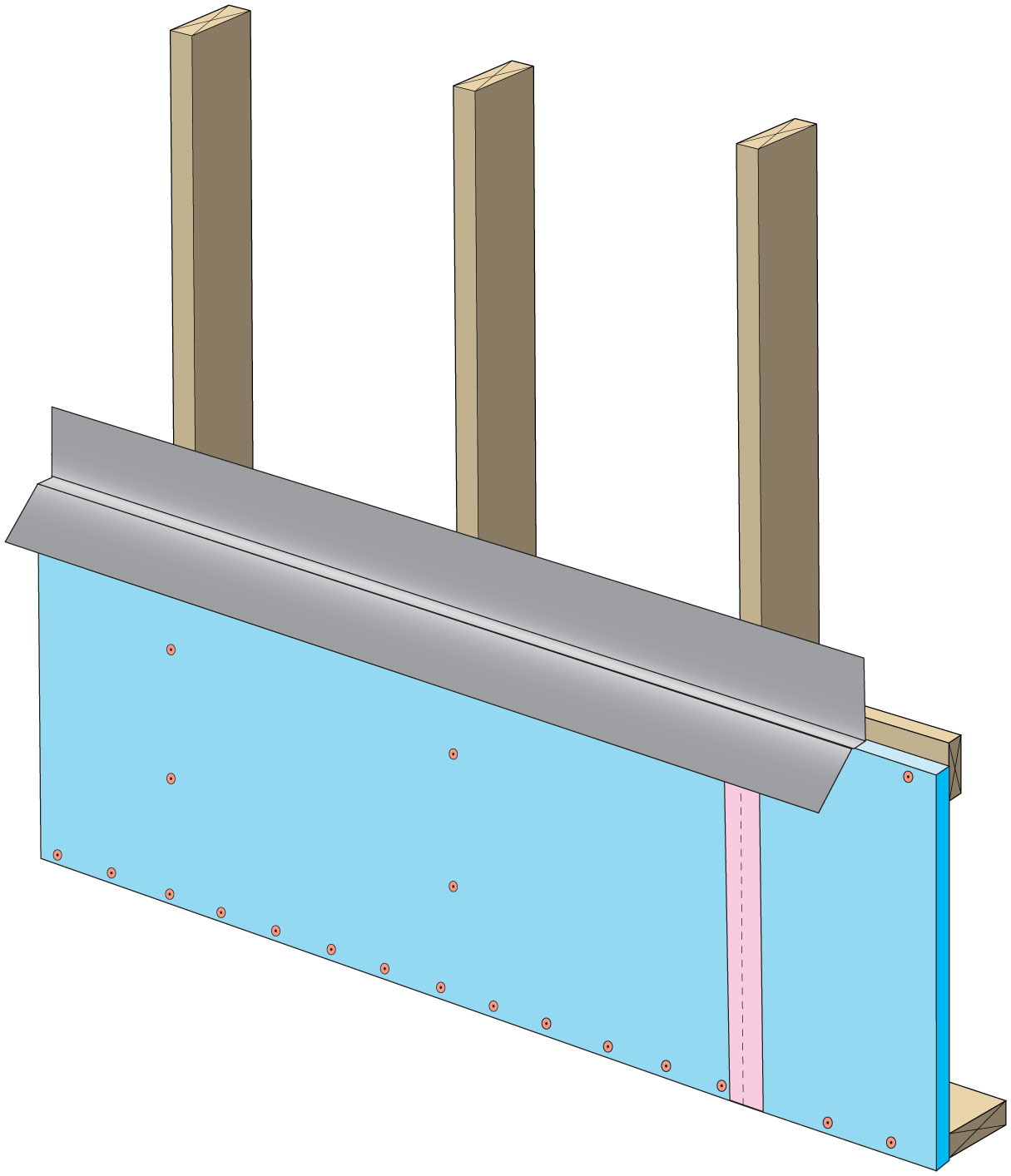
Continuous L-metal flashing integrated with underlayment at roof-wall intersections
Image
Correct seismic retrofit hardware for securing the sill plate to foundation wall
Image
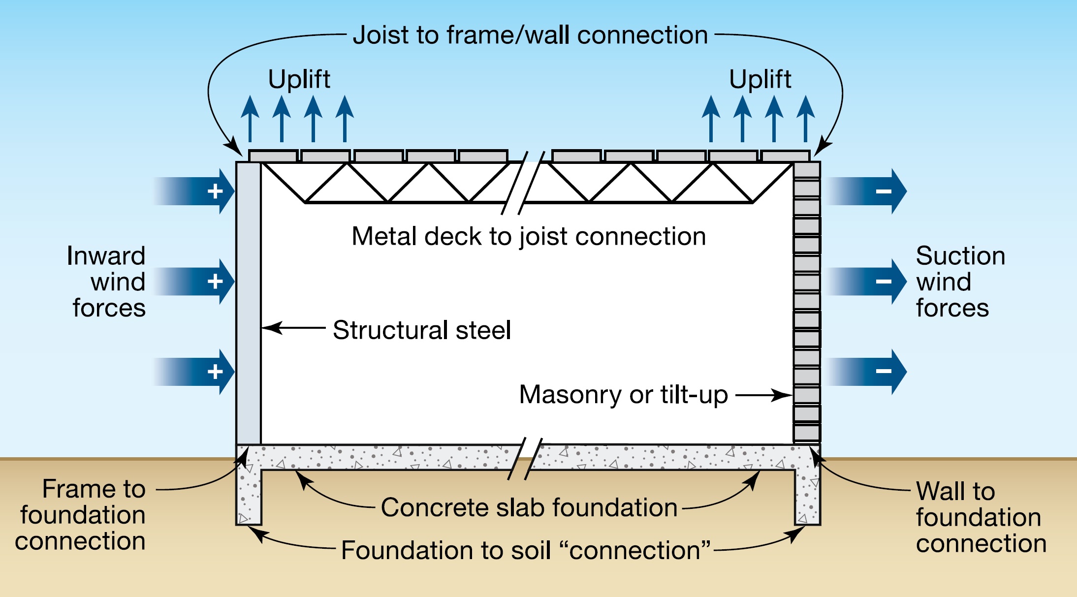
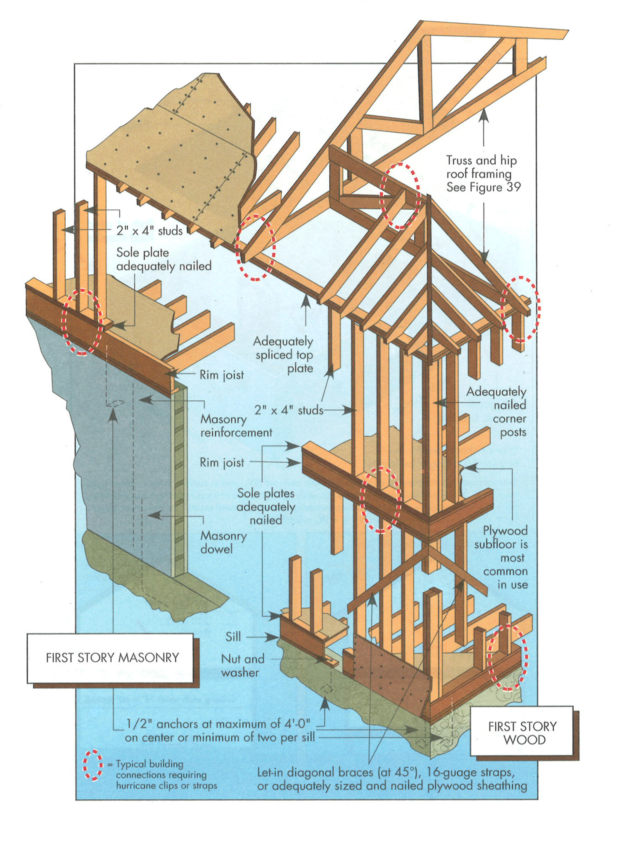
Critical connections for providing a continuous load path in buildings and storm shelters
Image
Image
Image
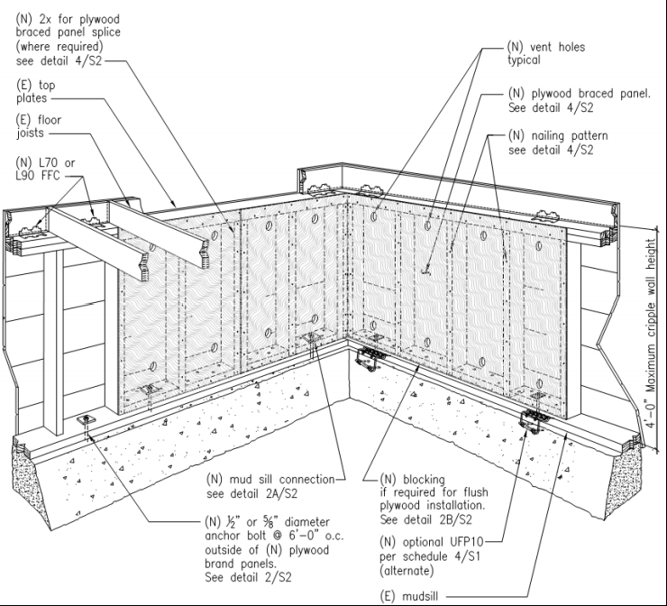
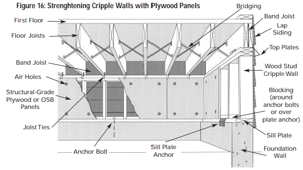
Detail for reinforcing a cripple wall to resist earthquake movement by installing anchor bolts and plywood reinforcement.
Image

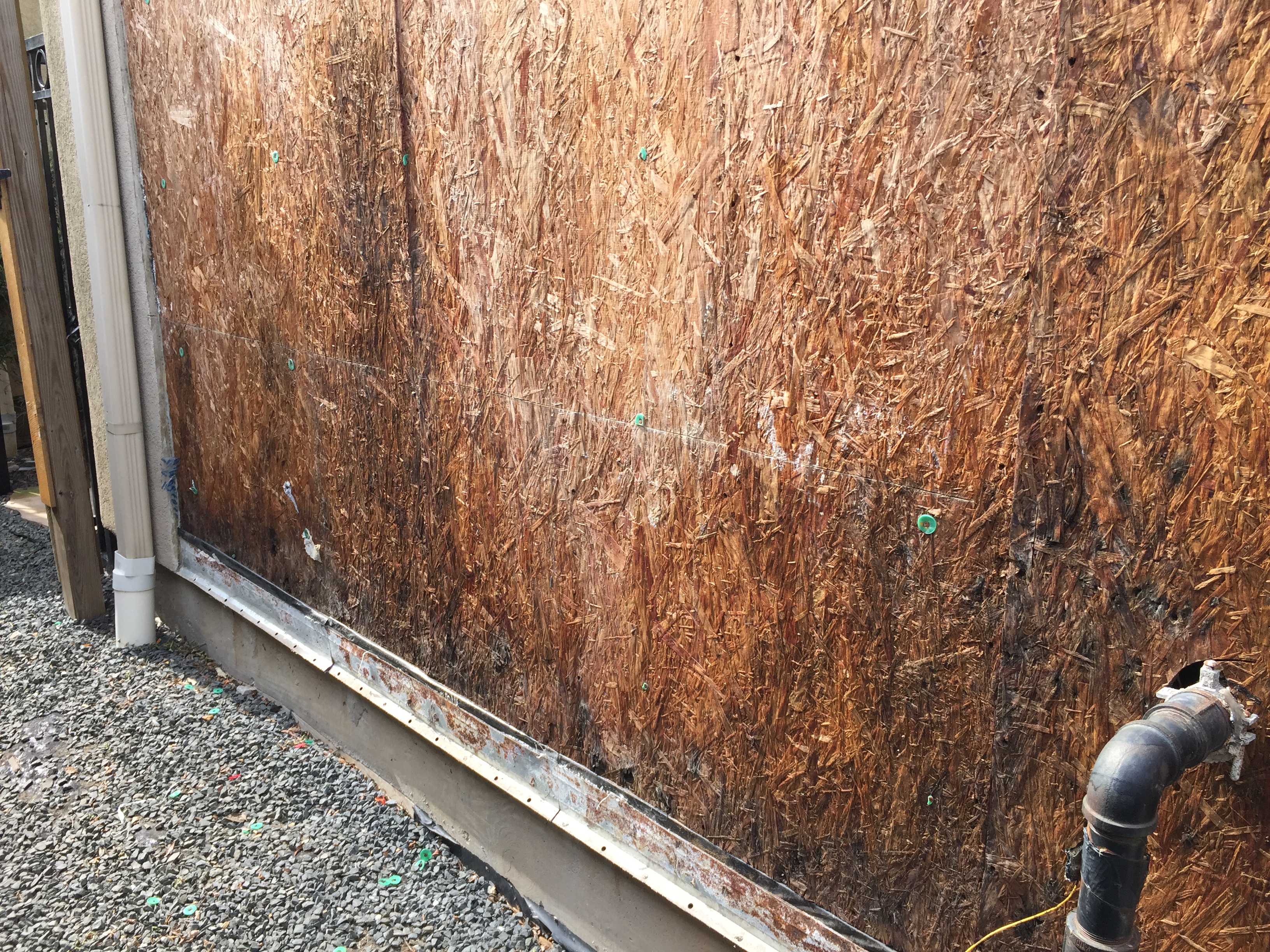
Durability concerns on a house continuously sheathed with a proprietary fiber structural panel used as bracing. Photo 1 of 2.
Image
Durability concerns on a house continuously sheathed with a proprietary fiber structural panel used as bracing. Photo 2 of 2.
Image
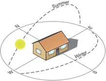
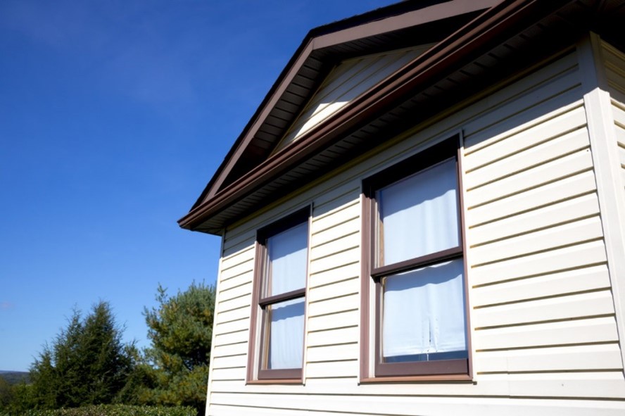
East- and west-facing walls receive significantly more sun than north- and south-facing walls in the summertime
Image
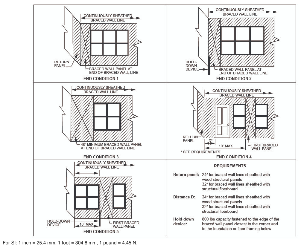
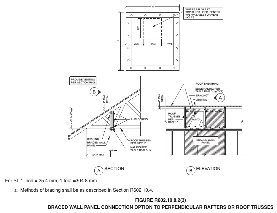
End conditions for braced wall lines with continuous sheathing, Figure R602.10.7 in the IRC
Image
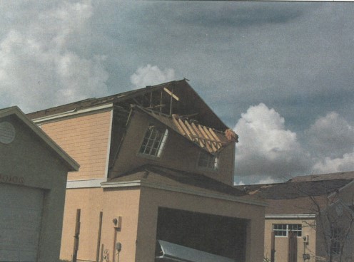
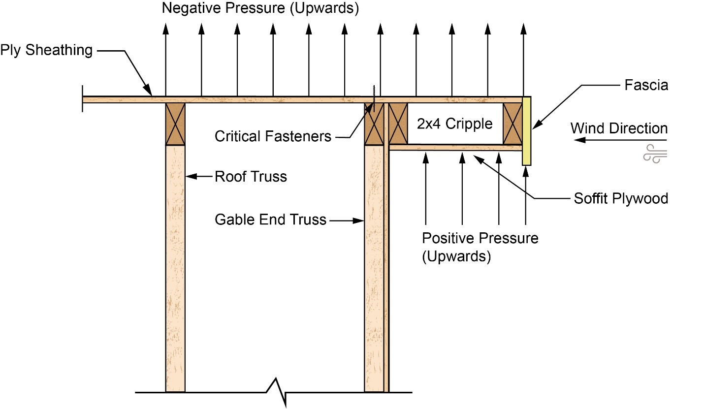
End wall failure under hurricane force winds due to inadequate bracing of the gable end wall.
Image
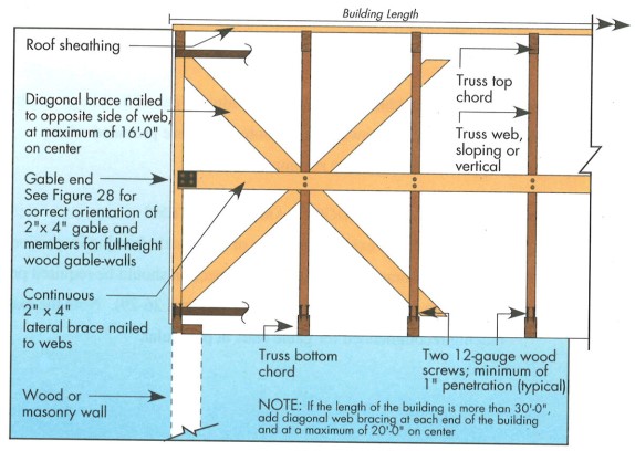
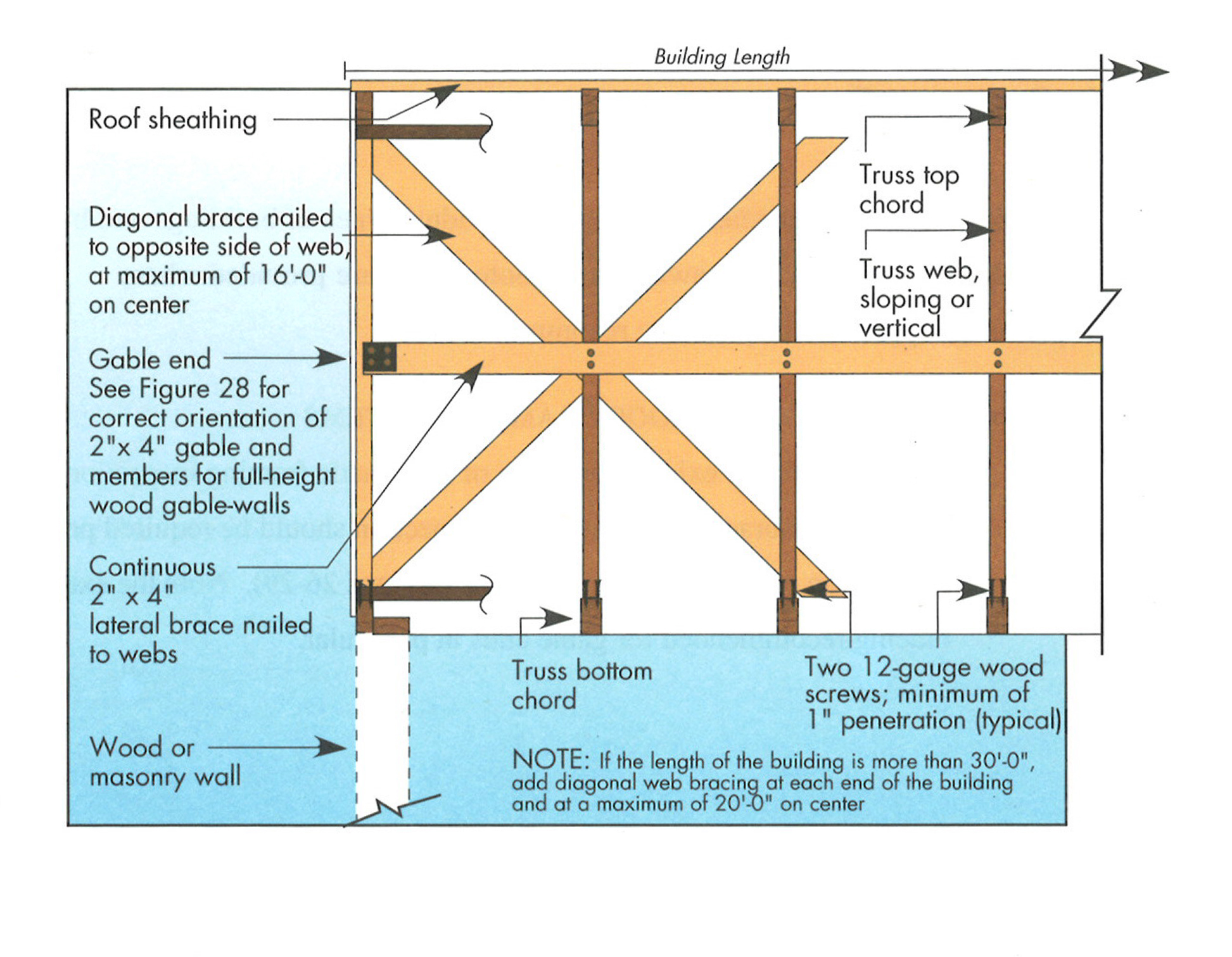
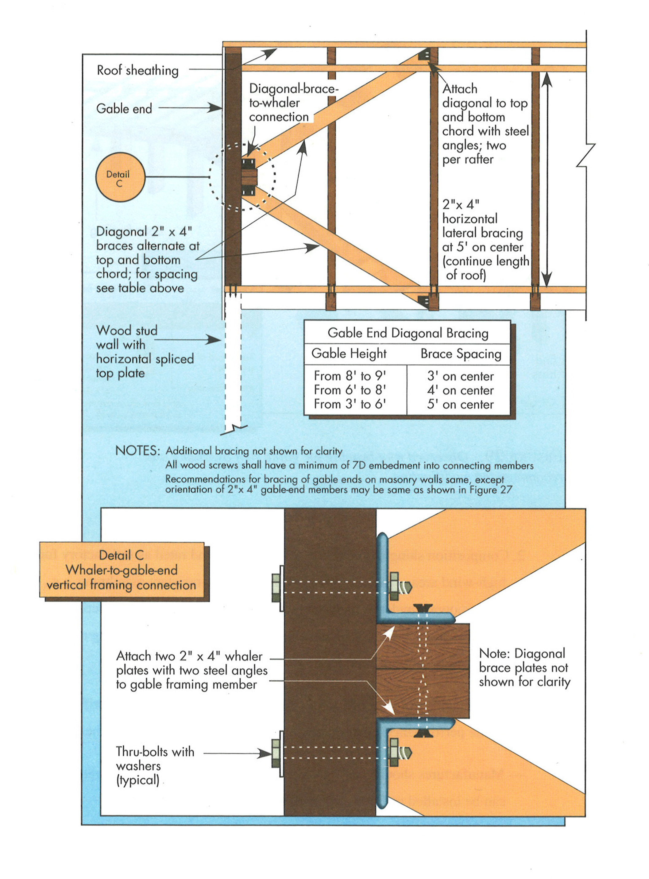
Example A of a gable truss and gable end wall bracing for a home in a hurricane region
Image

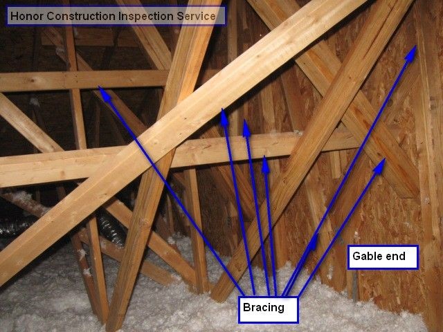
Example B of a gable truss and gable end wall bracing for a home in a hurricane region
Image
Image
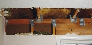
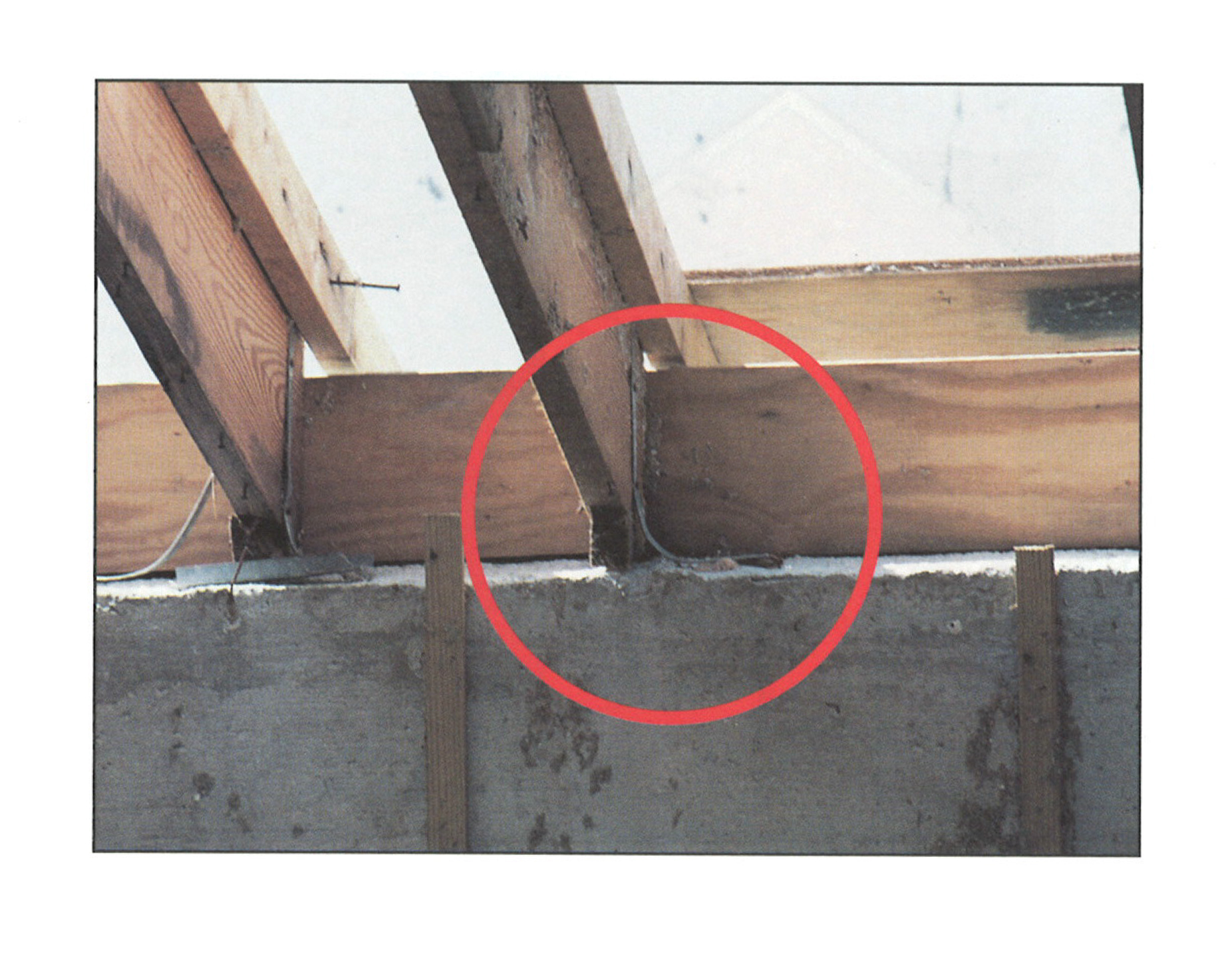
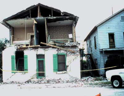
Example of masonry construction. Wall separated from building envelope due to inadequate vertical wall reinforcing in connection to horizontal tie-beam.
Image
Existing wall-to-lower roof transition retrofitted with a new strip of fully adhered air control transition membrane, new step flashing, new roof underlayment, and new cladding
Image
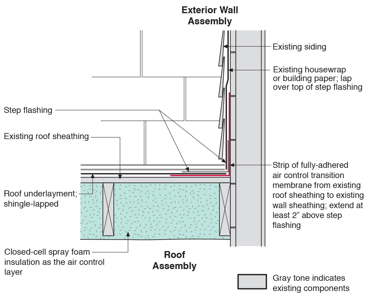
Existing wall-to-lower roof transition with a new strip of fully adhered air control transition membrane, new step flashing, new roof underlayment, and new cladding – view from eave
Image
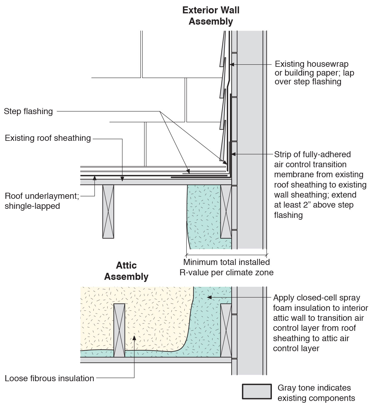
Existing wall-to-lower roof with attic transition with a new strip of fully adhered air control transition membrane, new step flashing, new roof underlayment, and new cladding – view from eave
Image
Externally insulated concrete slab-on-grade foundation with a turn-down footing, showing anchorage of the wall to the foundation for seismic resistance
Image
Externally insulated post-tensioned concrete slab-on-grade foundation wall with a turn-down footing showing anchorage of the wall to the foundation for seismic resistance
Image
Externally insulated post-tensioned concrete slab-on-grade foundation wall with a turn-down footing showing anchorage of the wall to the foundation for seismic resistance
Image
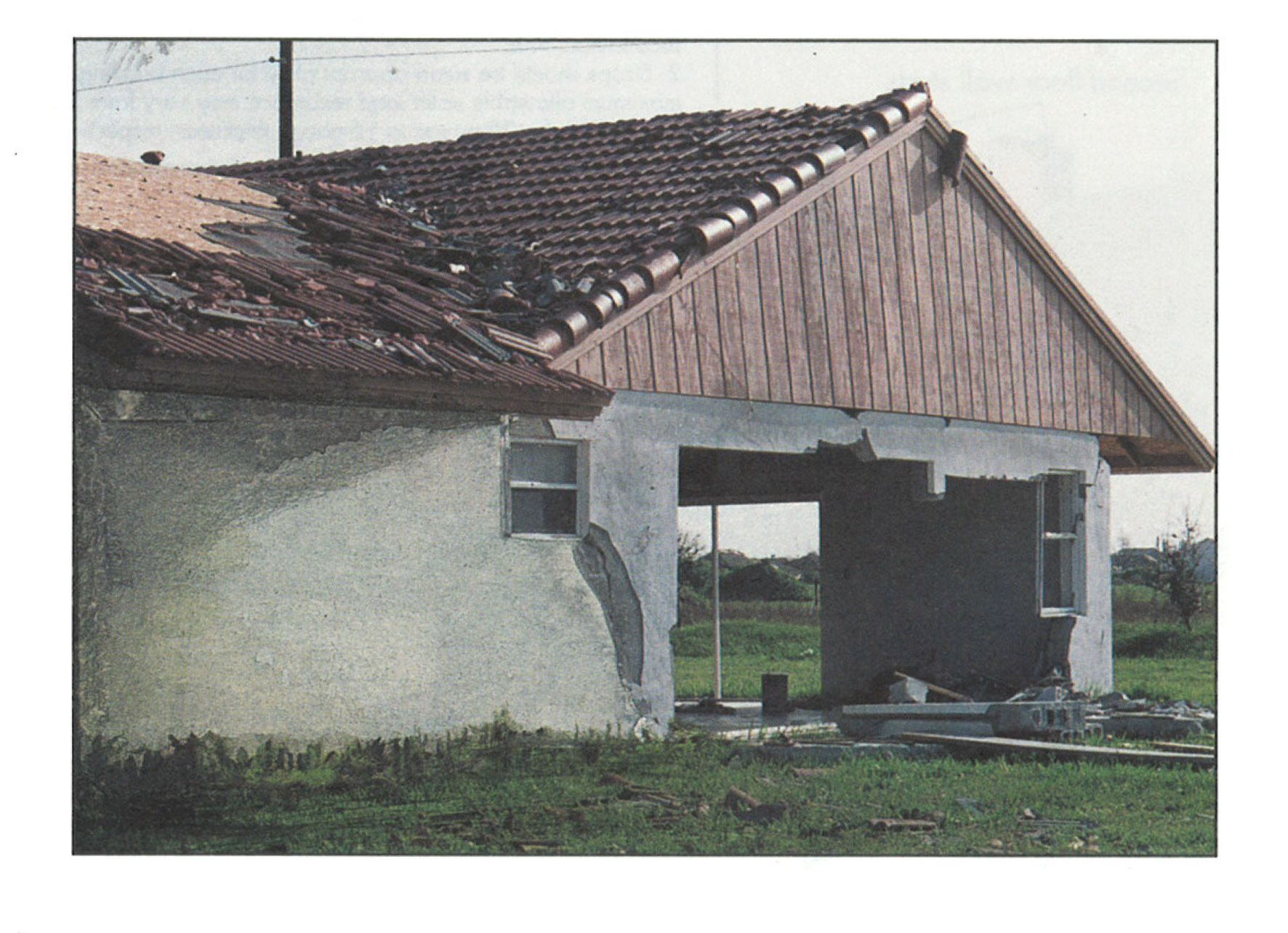
Failure of a freestanding concrete masonry end wall due to discontinuous tie-beam when exposed to hurricane force winds.
Image
Image
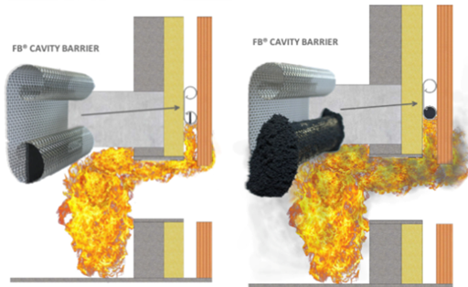
Fire barriers for ventilated wall cavities use thermally activated expansive materials to close off the ventilation space between the wall cladding and the sheathing during a fire while allowing air flow through the metal mesh during normal conditions
Image
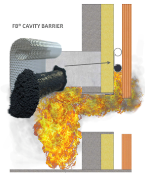
Fire barriers for ventilated walls use heat activated intumescent expansive materials to close off the ventilation space between the wall cladding and the sheathing during a fire while allowing air flow through the metal mesh during normal conditions
Image
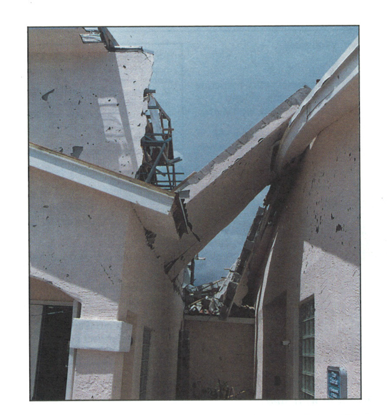
Firewall separation. Results from building corners being discontinuous with tie-beams.
Image
Image
Image
Image
Image
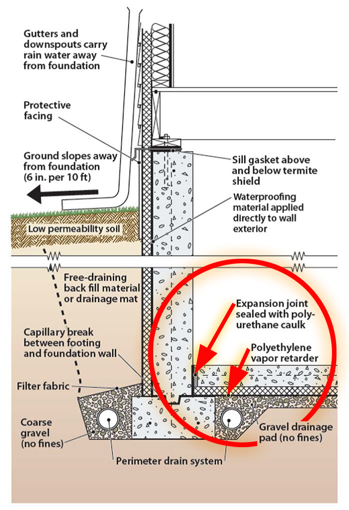
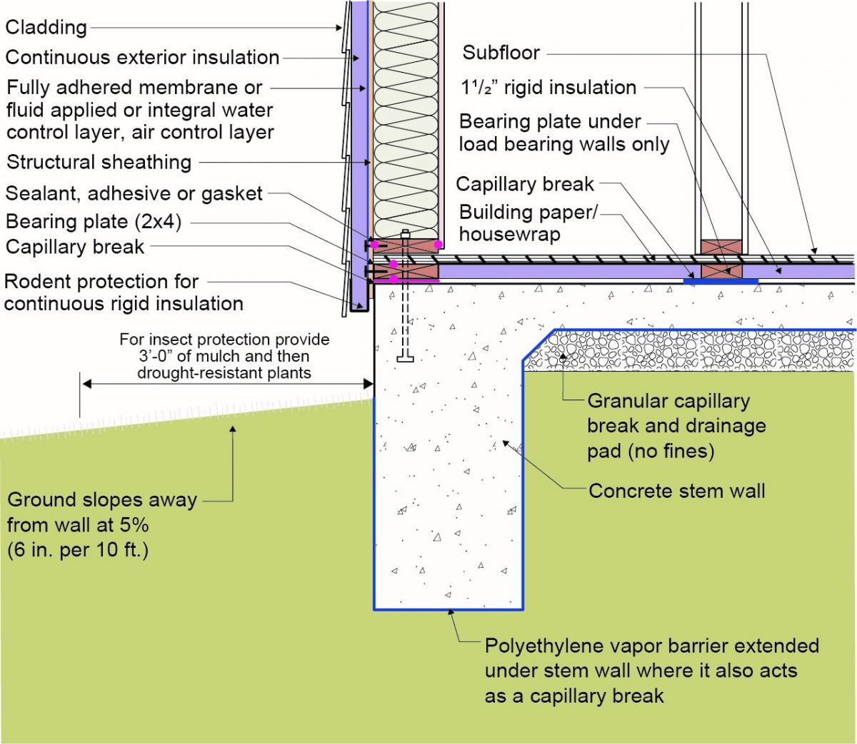
Good water management practices like sloping grade away from house, and installing gutters, perimeter drain pipe, a capillary break, and free-draining soils or drainage mat protect the foundation from water saturation.
Image

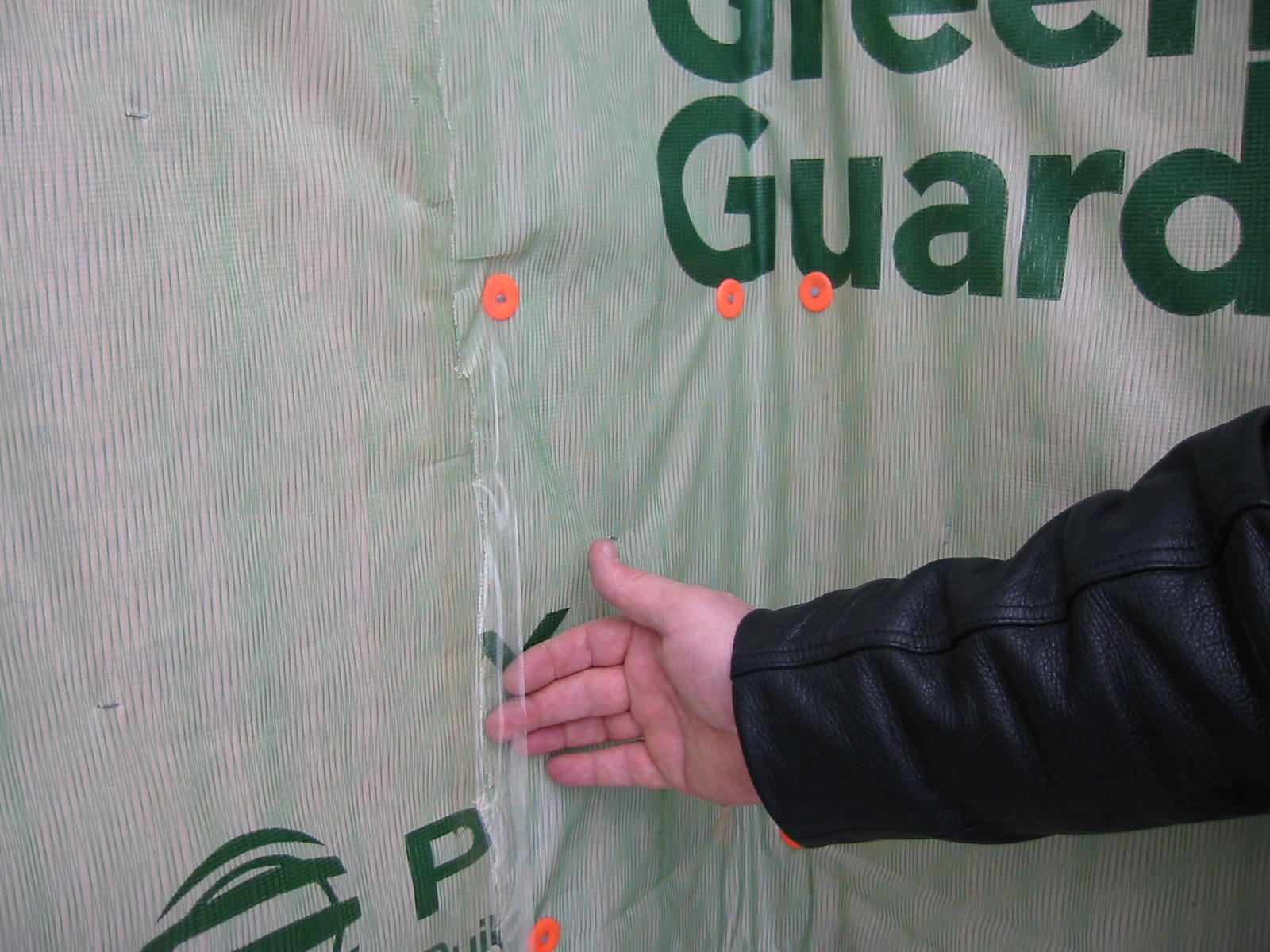
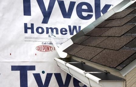
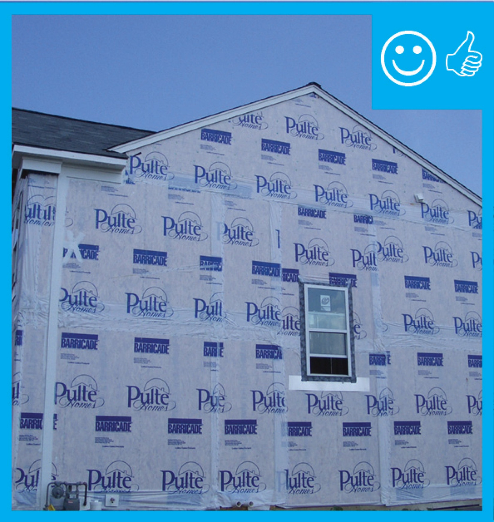
House wrap is sealed at all seams and overlaps flashing to serve as a continuous drainage plane over the exterior walls.
Image
Image
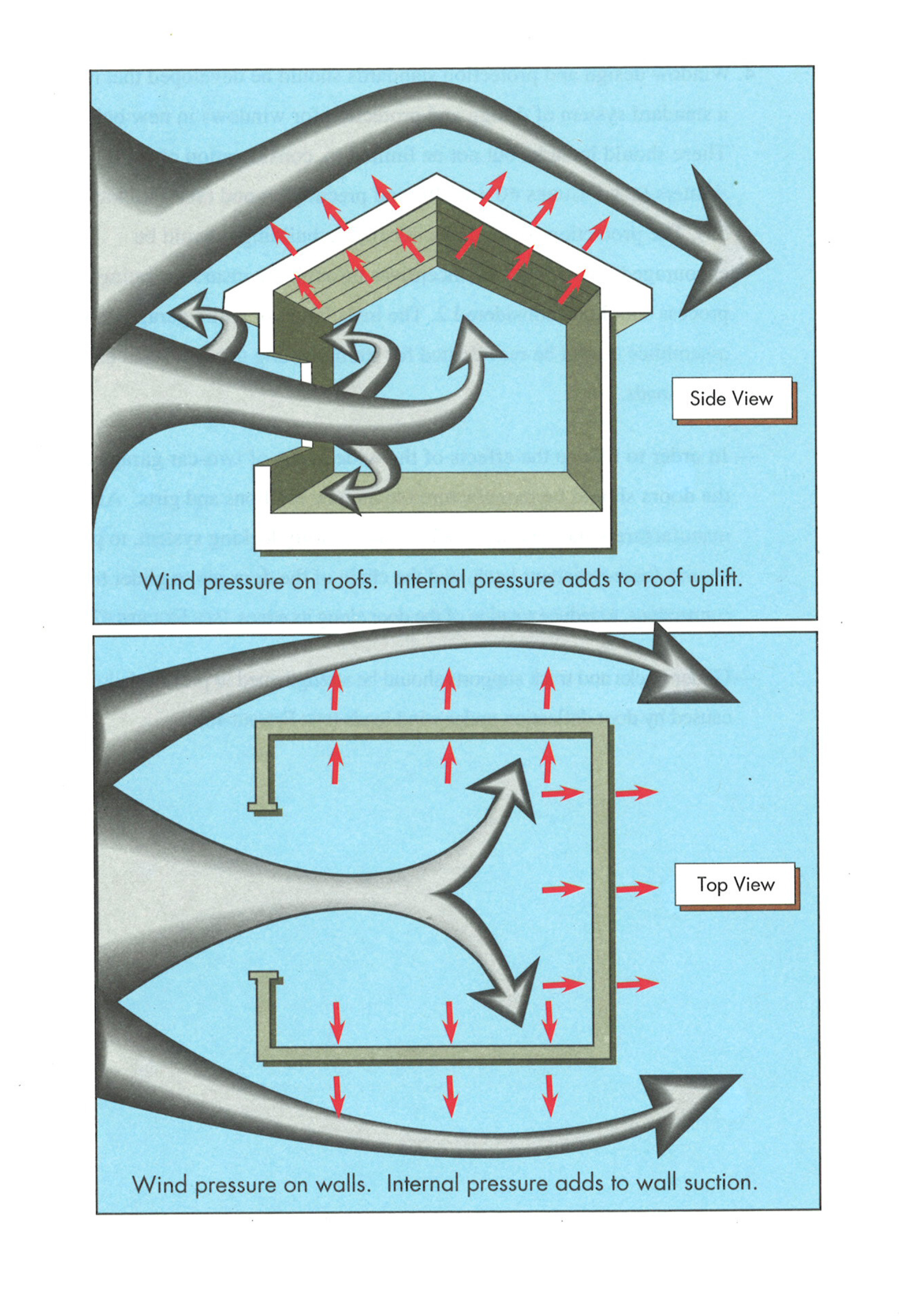
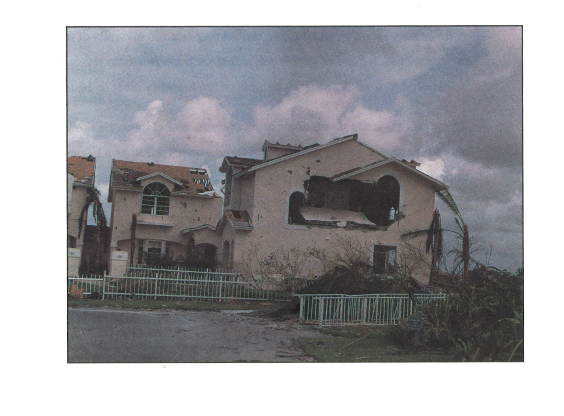
Hurricane force winds that breach external windows and doors can then cause failure of the entire building due to internal pressures on walls and roof.
Image
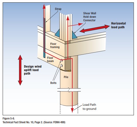
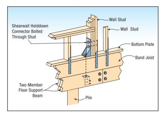
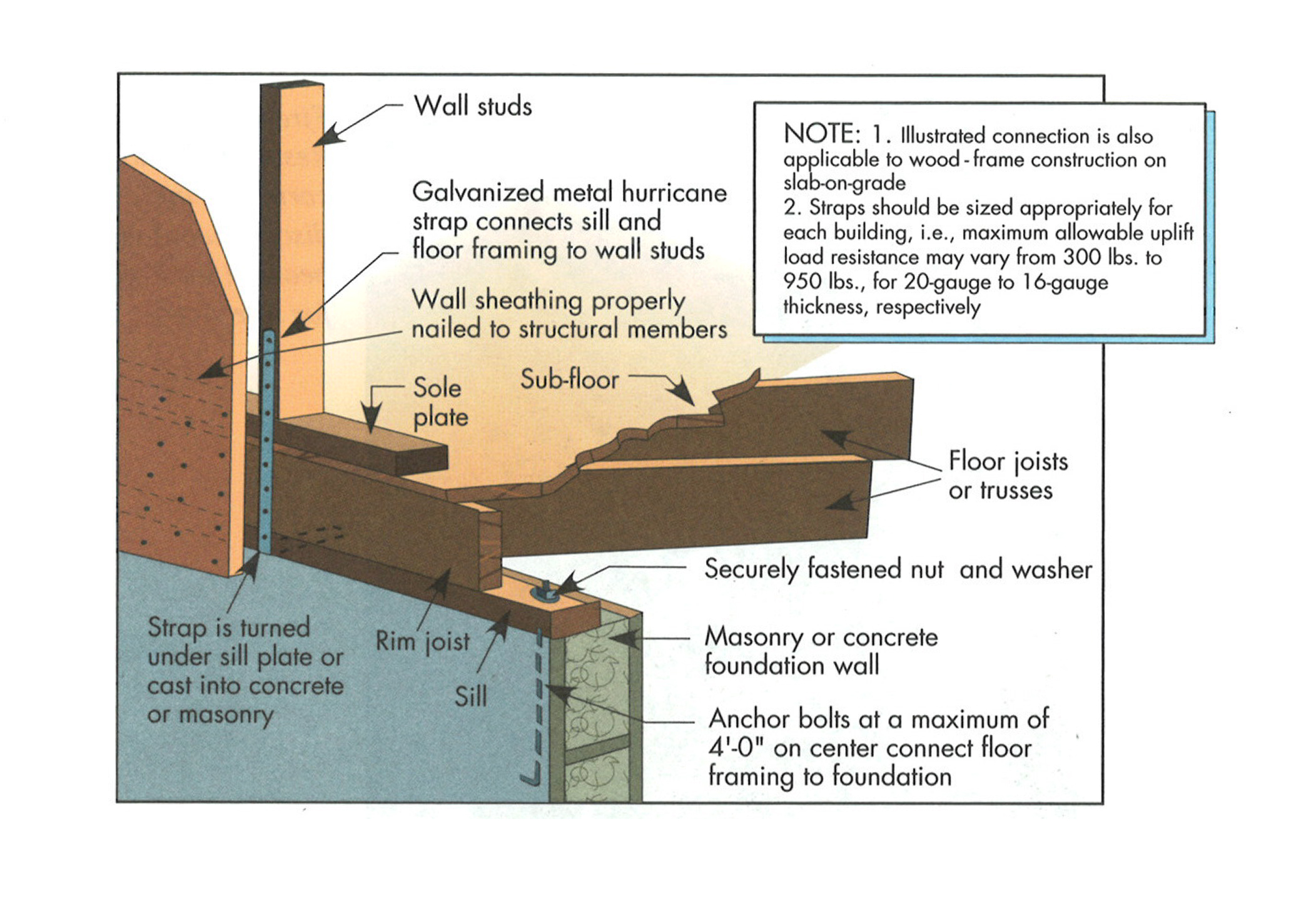
Hurricane straps, hold-down connectors, and bolts help to transfer loads from the building’s walls to its foundation, increasing resistance to vertical and horizontal pressures acting on the building from wind, waves, or ground movement.
Image
Image
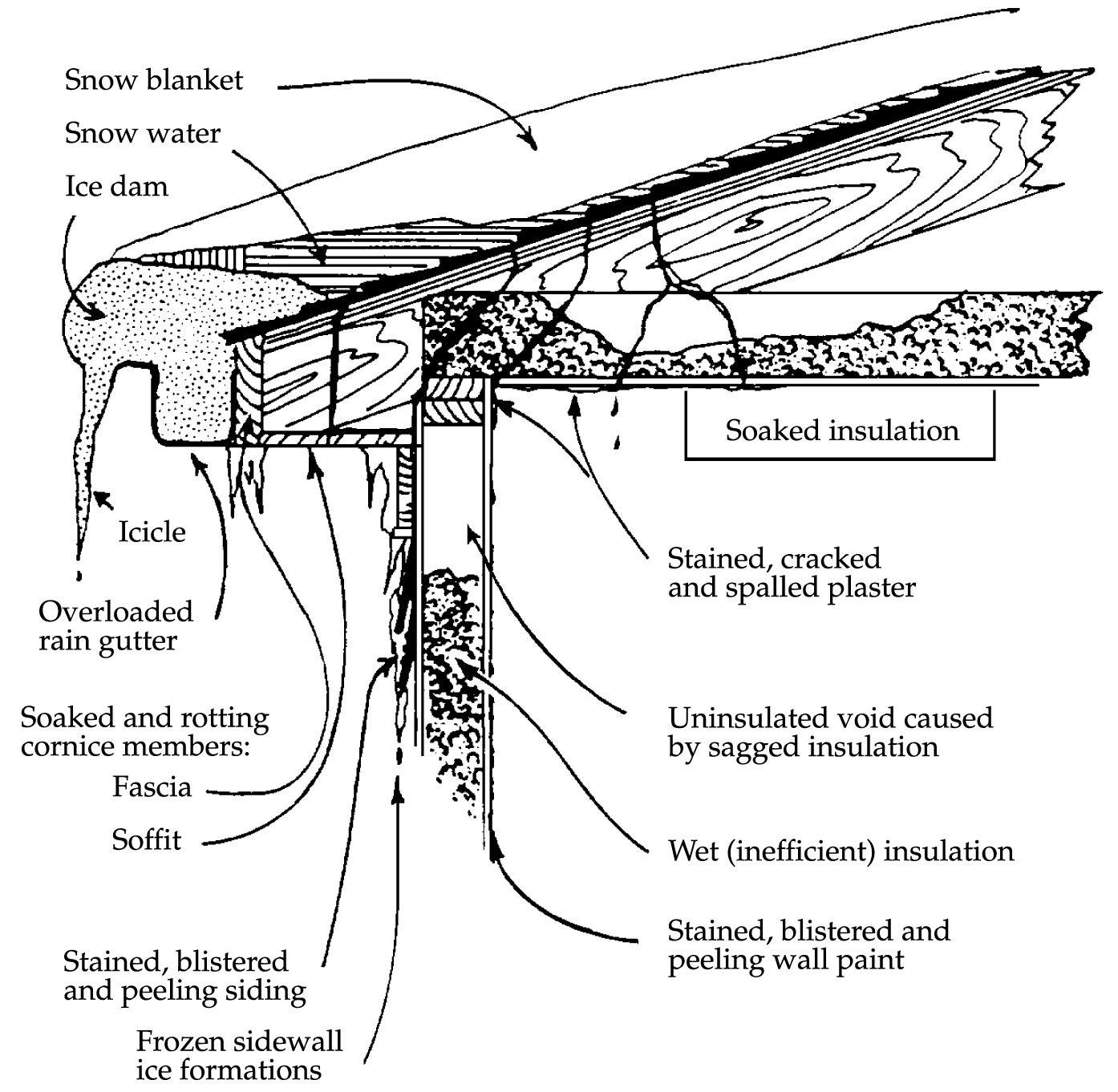
Ice dams formed by melting of snow on roofs can affect roofs, walls, ceilings, siding, and insulation.
Image
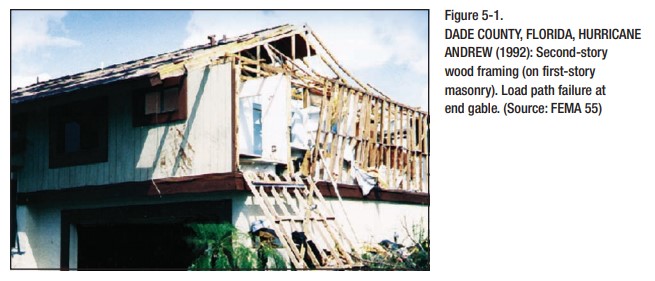
Improper continuous load path design lacking bracing results in the failure of gable end walls under high wind conditions.
Image
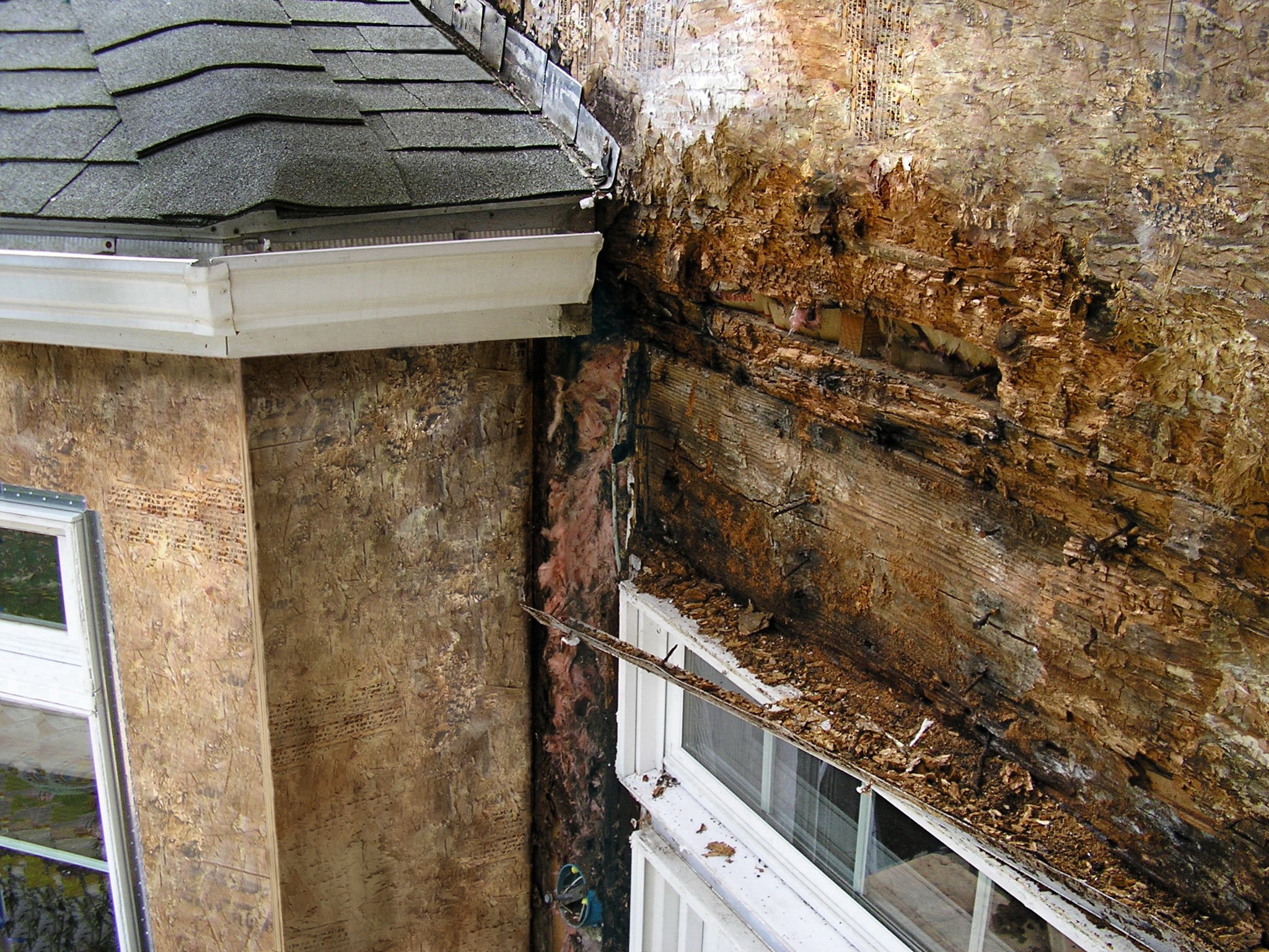
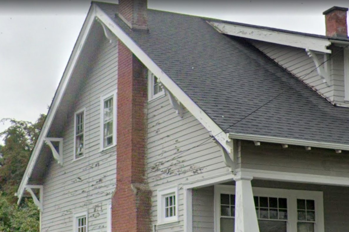
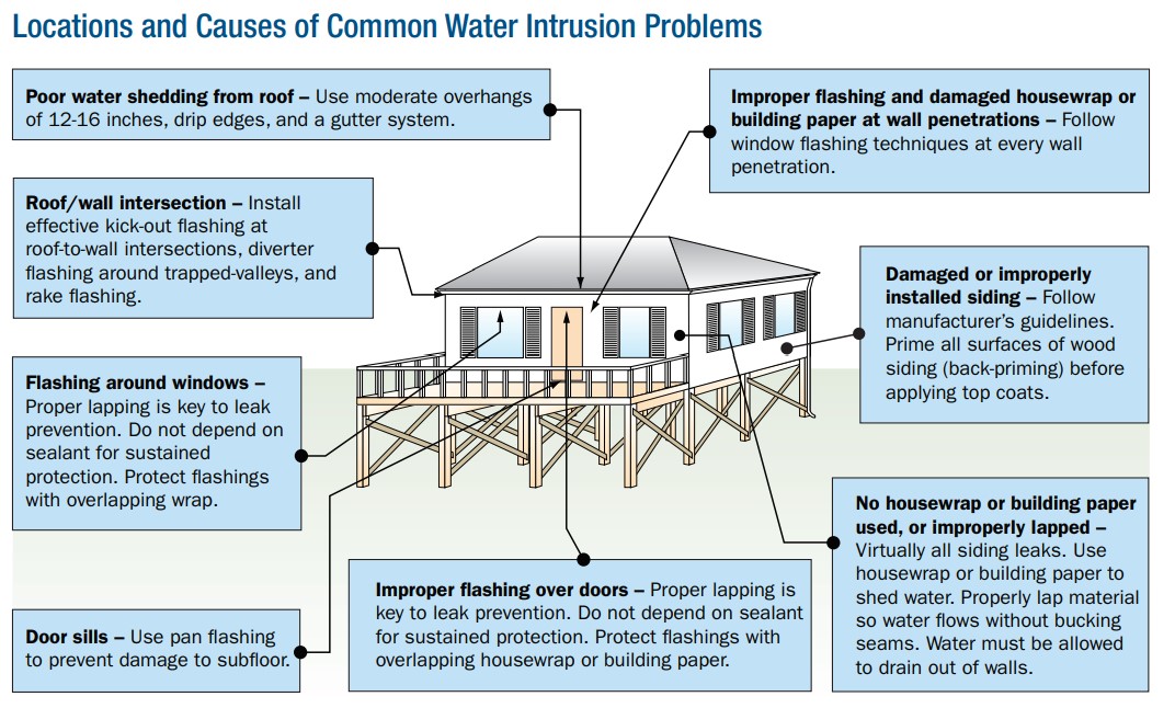
Improper flashing can allow rain water into walls, causing significant damage
Image
Image
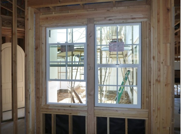
In areas prone to high winds and hurricanes, double vertical “jack trim” and horizontal “header” and “sill” studs are recommended on all sides of window and door openings.
Image
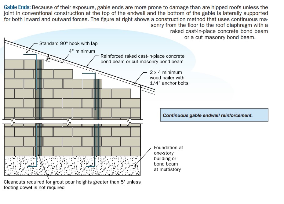
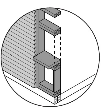
In high wind areas, provide lateral support to masonry end walls to resist high winds.
Image
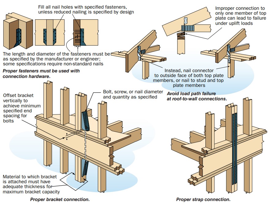
In high-wind regions, special hardware is used for most framing connections; toe-nailing is not acceptable.
Image
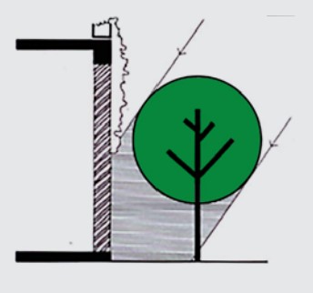
In hot climate zones, shade building surface with vegetation for passive cooling.
Image
Incorrectly done seismic retrofit, the plywood sheathing is not nailed to the mud sill and therefore it is not providing any shear strength
Image
Image
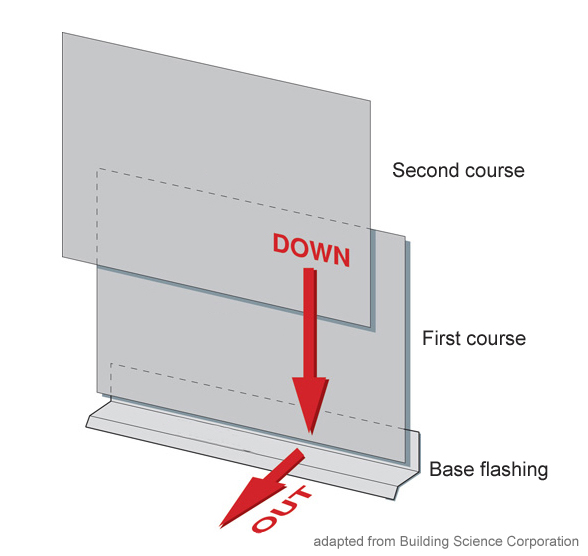
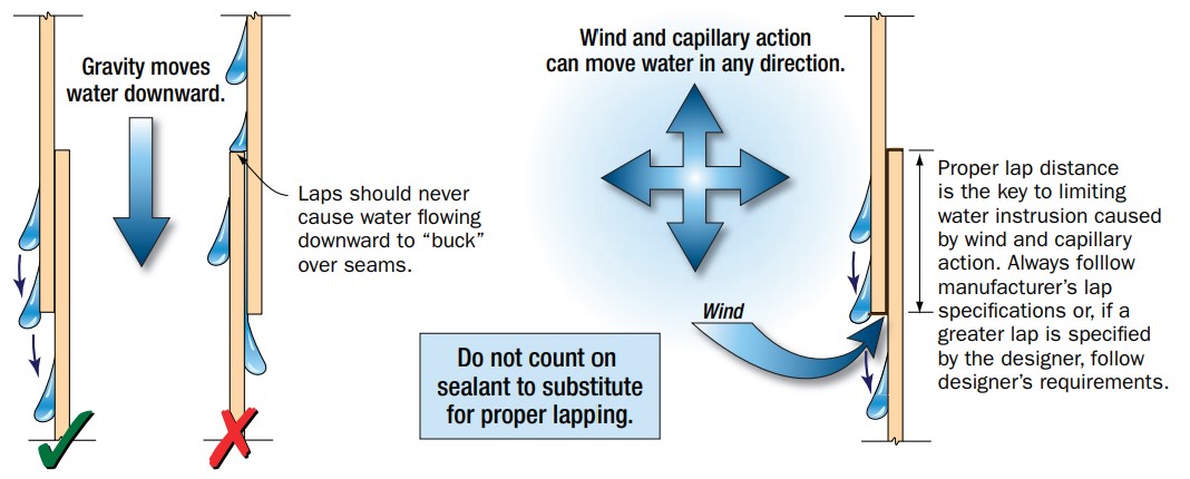
Install all layers of the drainage plane to overlap, not underlap, to direct bulk water down and out of the wall.
Image
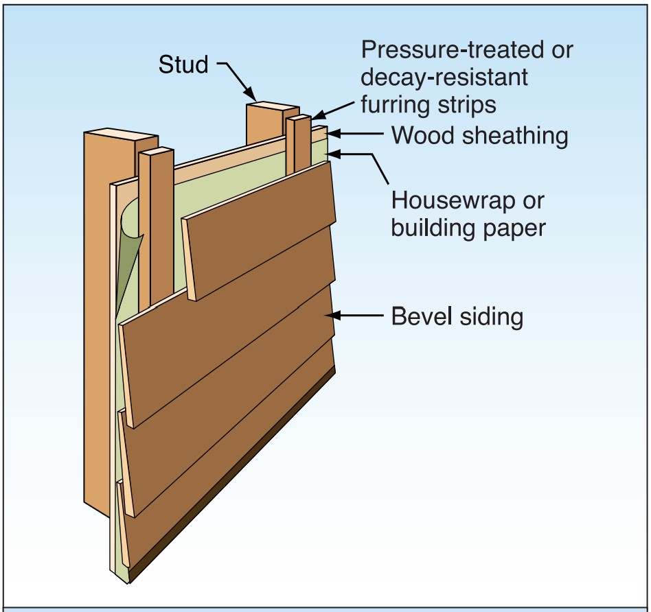
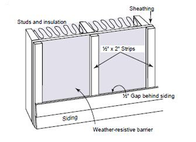
Install furring strips over house wrap to provide a rainscreen behind wood siding.
Image
Image
Image
Install shingle starter strip then kick-out diverter; attach to roof deck but not sidewall
Image
Image
Install the house wrap. Cut house wrap to fit over diverter and tape top of cut wrap
Image

Image

Image

Image
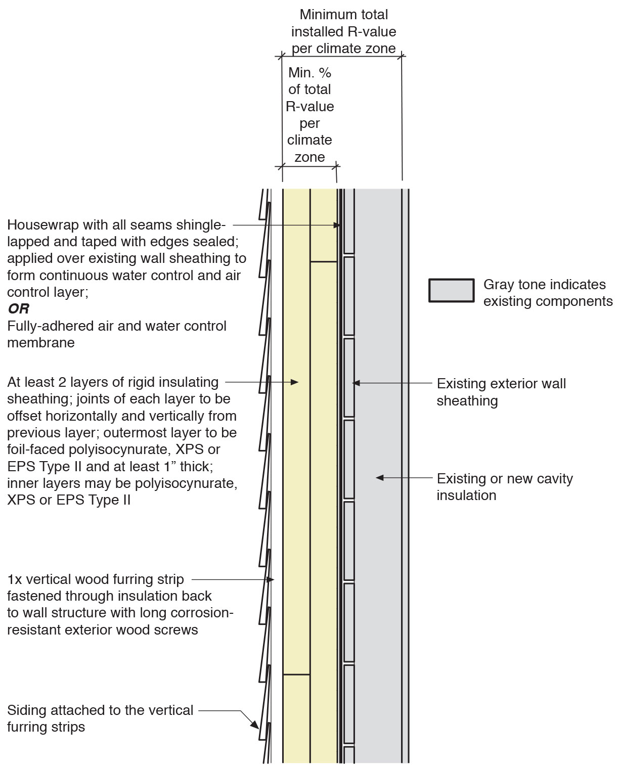
Insulating sheathing is installed on exterior of an existing framed wall with water control between existing sheathing and insulating sheathing
Image
Image
Image
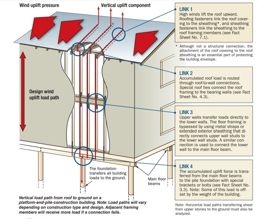
Key connection points for a continuous load path for earthquake and high wind disaster resistance
Image

Light colors have been used on exterior walls and roofs to keep buildings cooler in hot climates for centuries, as shown by this traditional building in Morocco, built in the early 1800s
Image
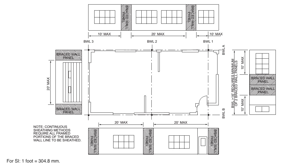
Location of Braced Wall Panels and Braced Wall Lines, Figure R602.10.2.2 in the IRC
Image
Image
Image
Image
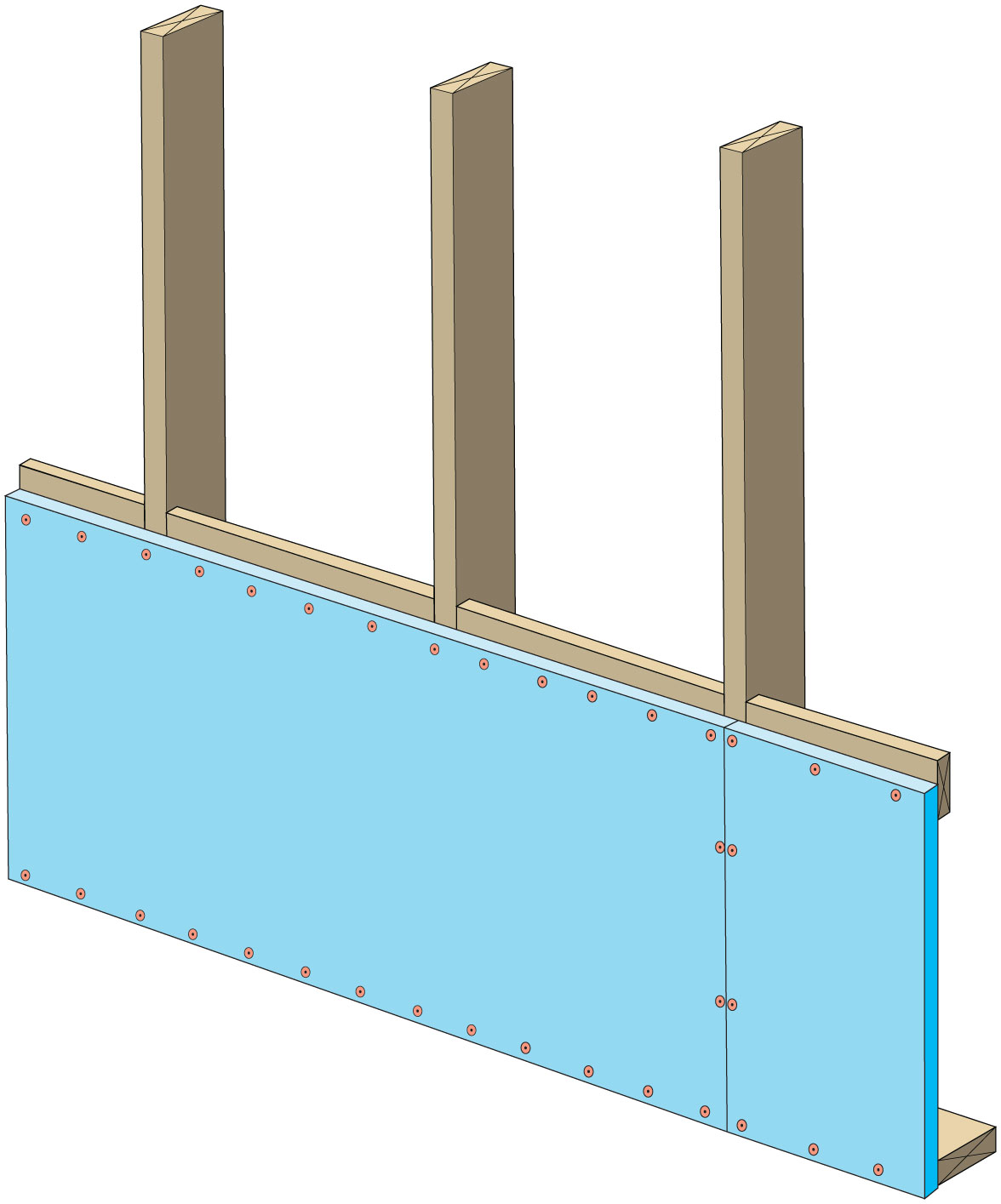
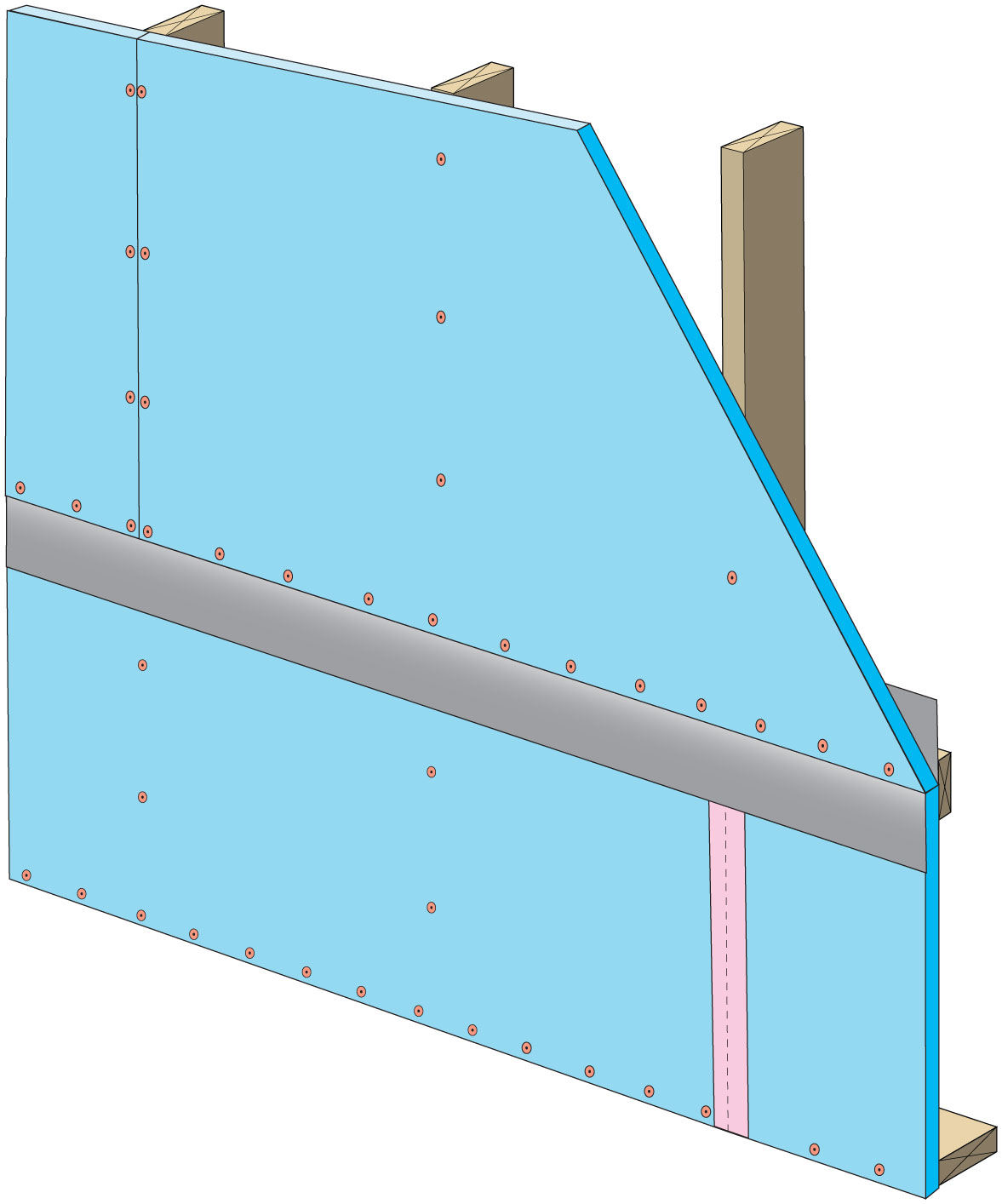
Lower-story wall anchorage to masonry (or concrete) base. Straps properly nailed at wall studs.
Image
Image
Image
Image
Moisture-resistant plastic and fiber cement exterior trim and cladding are indistinguishable from wood building elements.
Image
Image
Image
Image
Place first shingle and next section of sidewall flashing over upper edge of diverter
Image
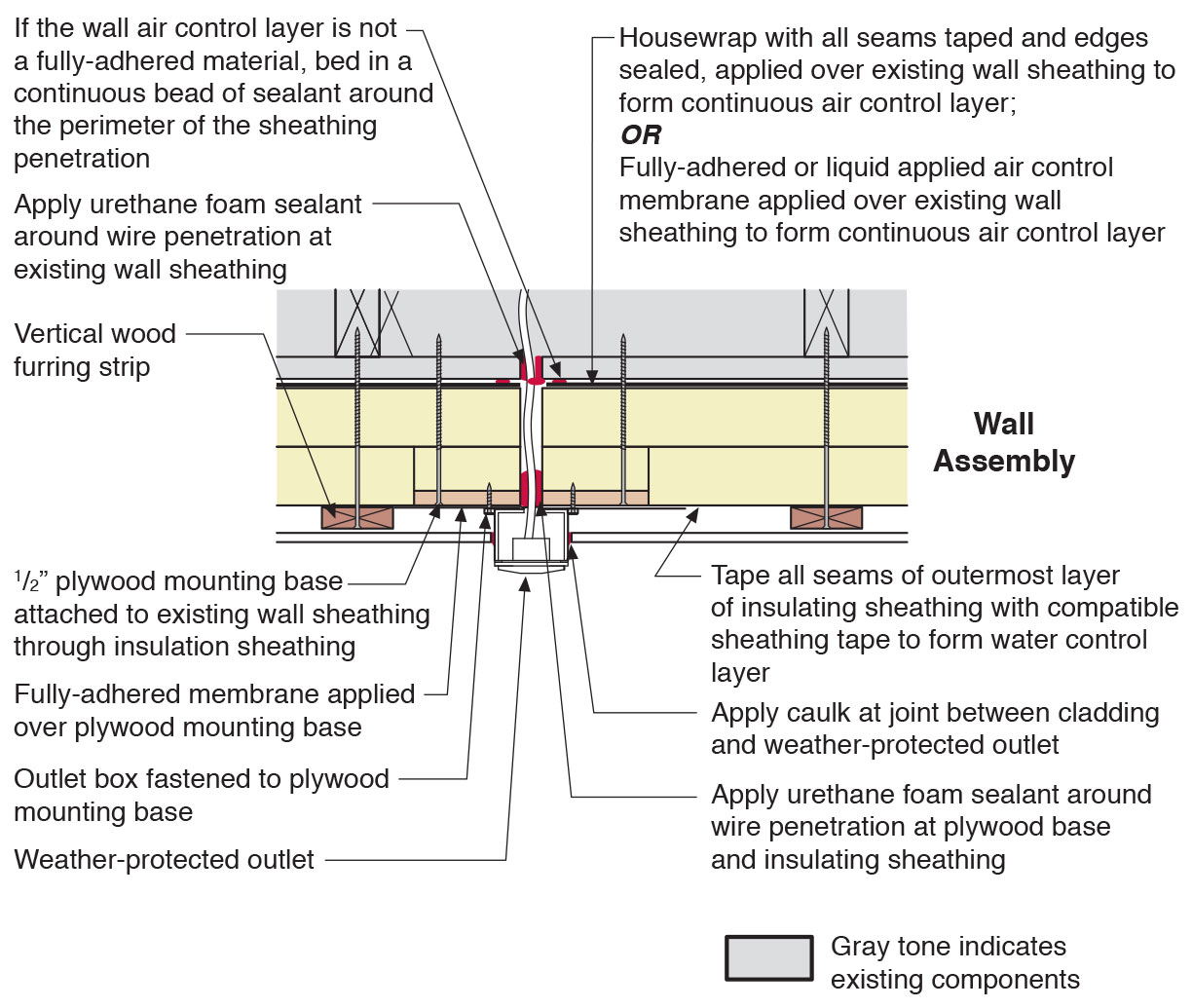
Plan view of electric box installation in exterior wall showing flashing and air sealing details
Image
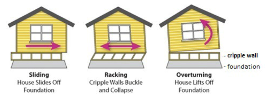
Possible failure scenarios due to house sitting on poorly braced and secured cripple wall
Image
Image
Image
Image
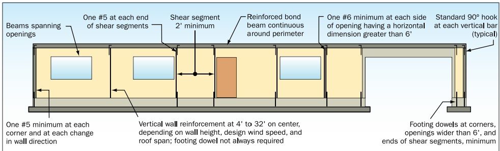
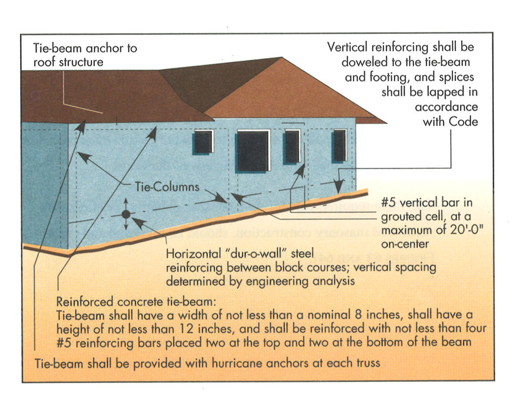
Properly reinforce masonry walls in coastal locations to resist high winds and waves.
Image

Image
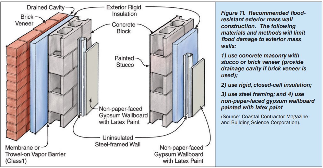
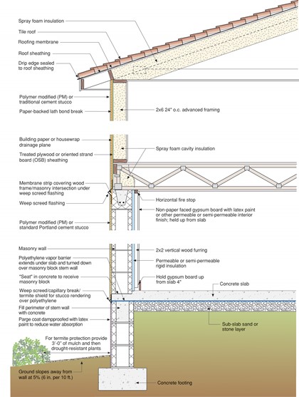
Recommended flood resistant wall construction for concrete block walls with stucco or brick veneer.
Image

Image
Image
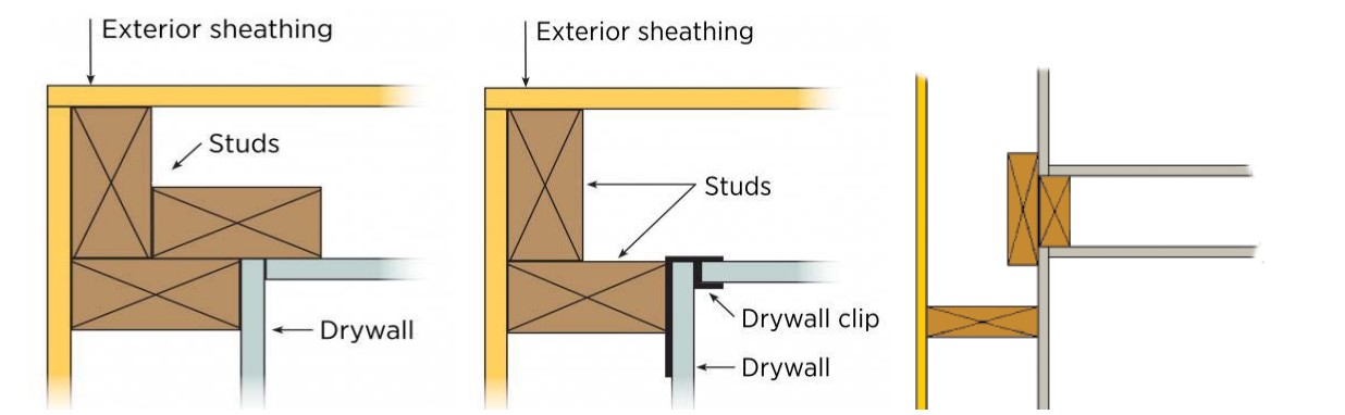
Reduce thermal bridging in hot climate zones by using an intersecting exterior wall framing technique as shown here.
Image
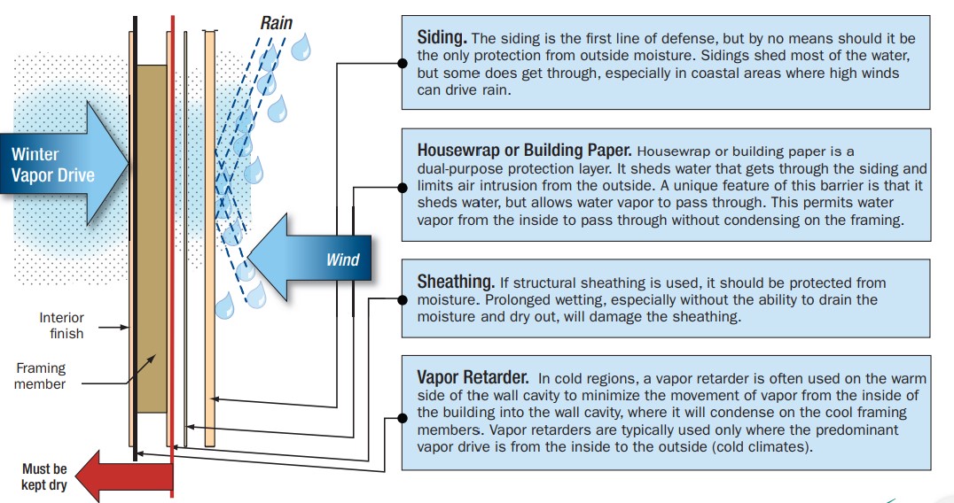
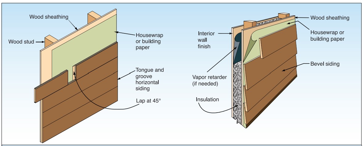
Redundant moisture barriers including siding, house wrap, and coated sheathing can help protect walls from excess moisture, while vapor retarders prevent vapor from entering the wall from the house, for example from a bathroom or kitchen.
Image

Image
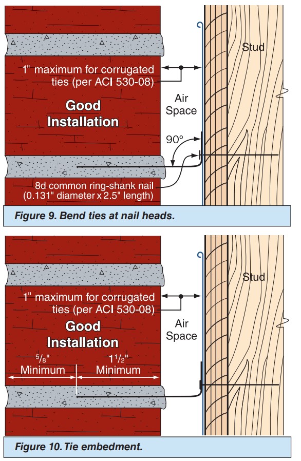
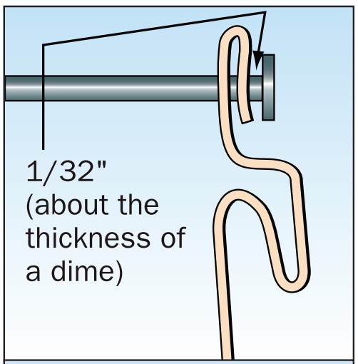
Right – The ties are bent at a 90 degree angle at the nail head and embedded into the mortar joint at least 1.5 inches.
Image
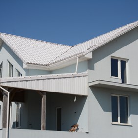
Right - Covered porches protect the south-facing windows and doors of this building from solar heat gain.
Image

Right - A continuous load path connects the roof and wall framing to the foundation.
Image
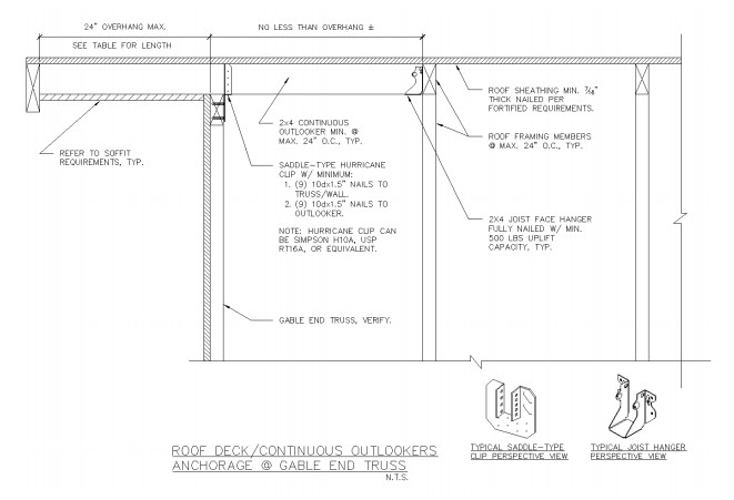
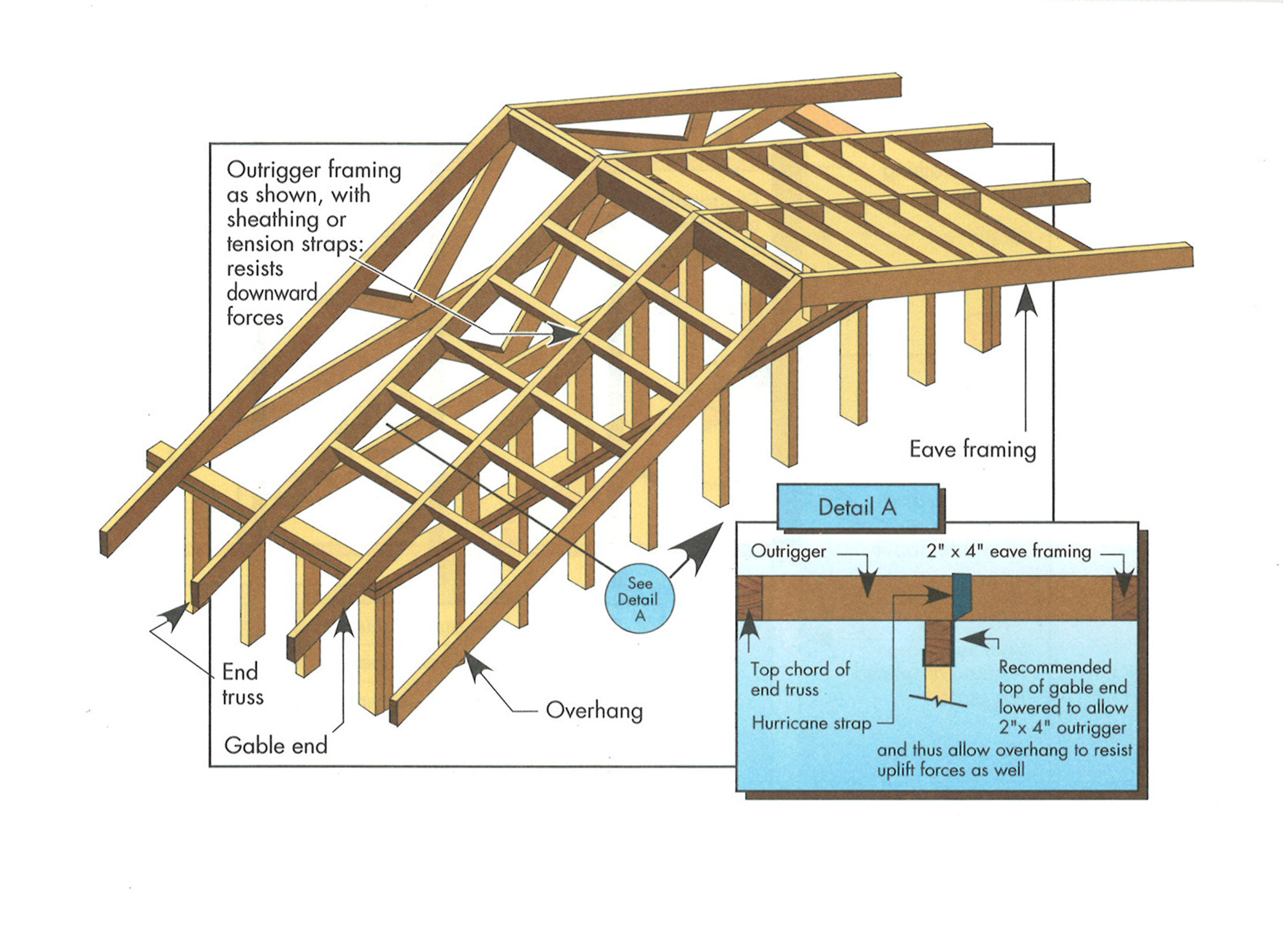
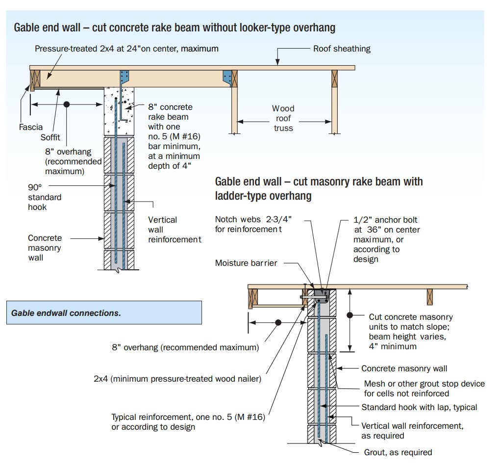
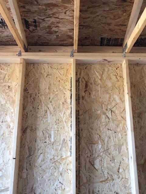
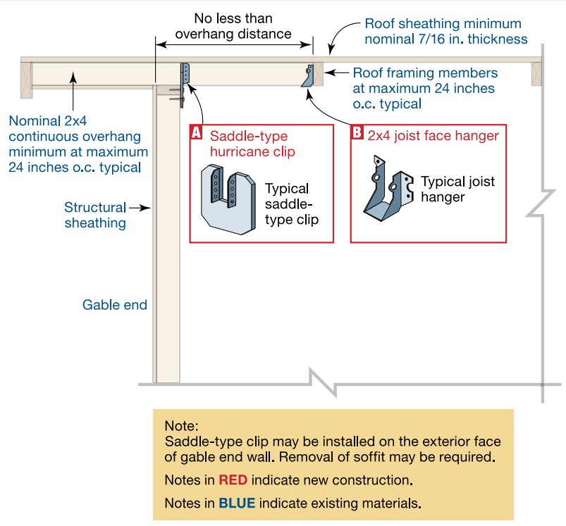
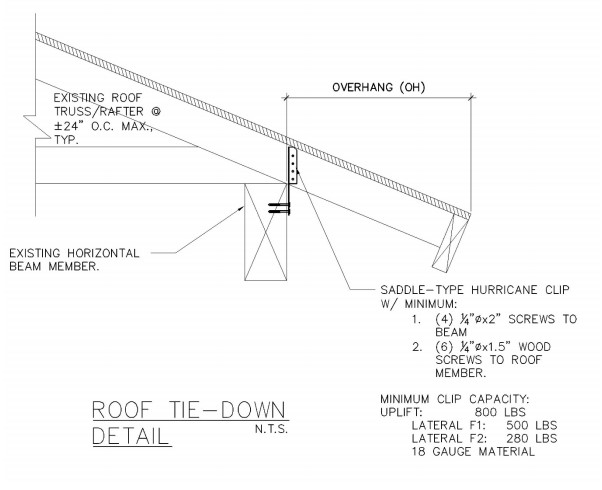
Right - Anchorage to increase the wind uplift resistance of outlookers forming the overhang at a gable end truss wall.
Image

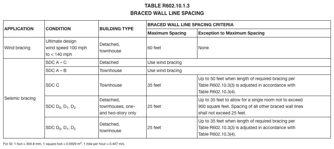
Right - Braced wall line spacing is correctly calculated for determining wall bracing in accordance with the IRC.
Image

Right - Engineered portal frames are used for wall bracing to resist wind and earthquake loads.
Image
Right - Foil-faced polyisocyanurate rigid foam is attached to the existing exterior wall with vertical wood furring strips
Image

Right - The wall framing is connected to roof framing with metal ties for hurricane-resistant construction.
Image
Right - These raised heel roof trusses provide 16 inches of space over the outer walls for full insulation coverage at the attic perimeter.
Image
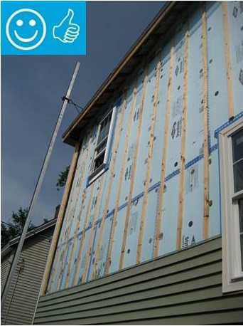
Right - This foil-faced polyisocyanurate rigid foam is installed on an existing exterior wall and the seams are taped so the rigid foam can serve as a water control layer
Image
Right - XPS foam insulation is attached to the existing exterior wall with wood furring strips that serve as a nail base for the siding and are installed vertically to allow for drainage and drying behind the siding
Image
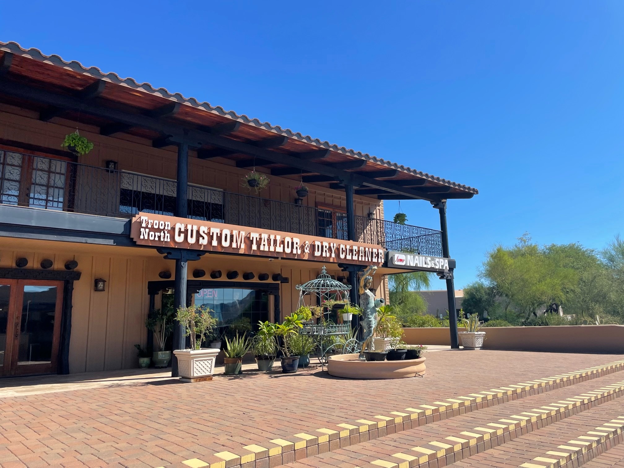
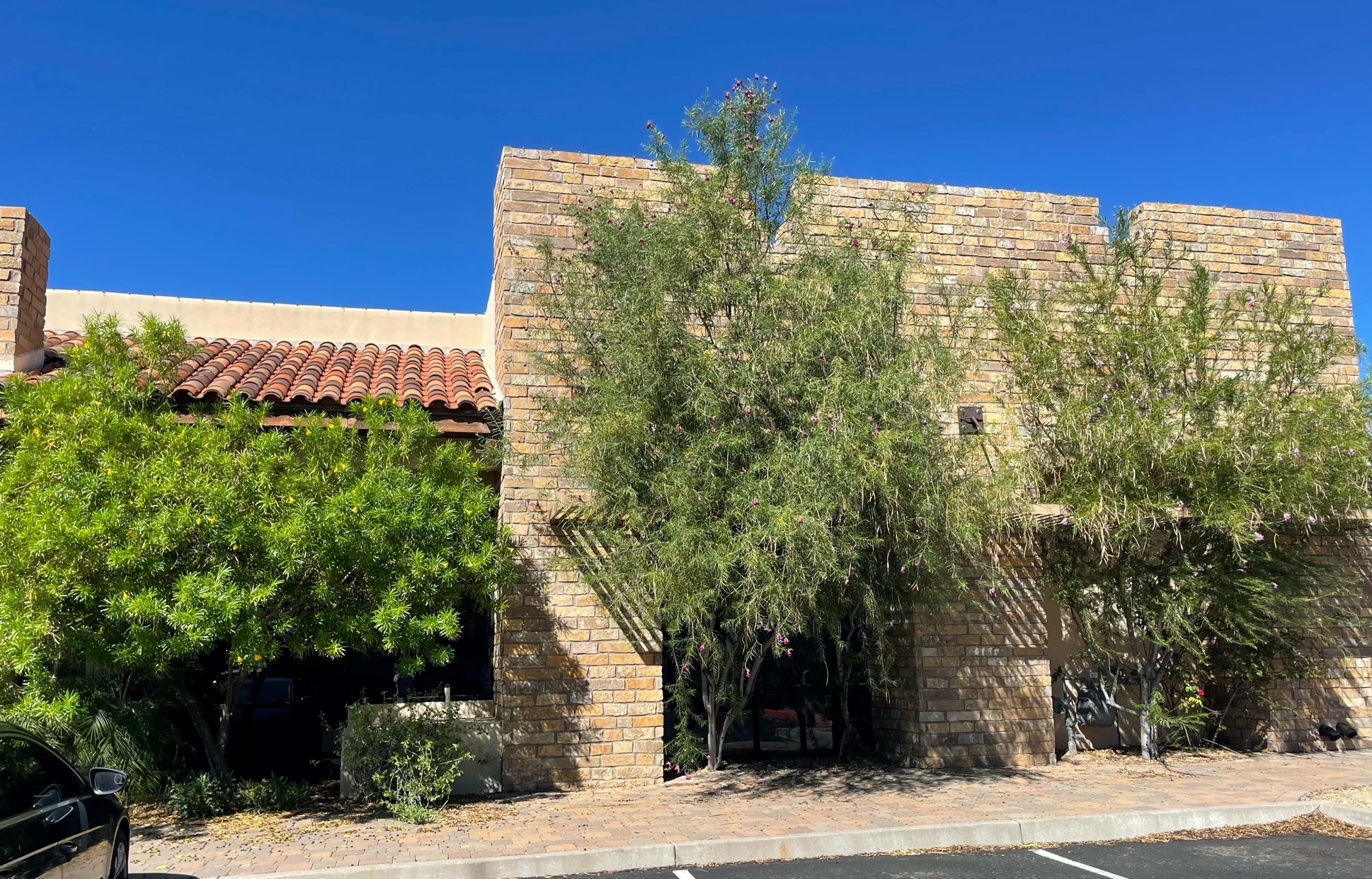
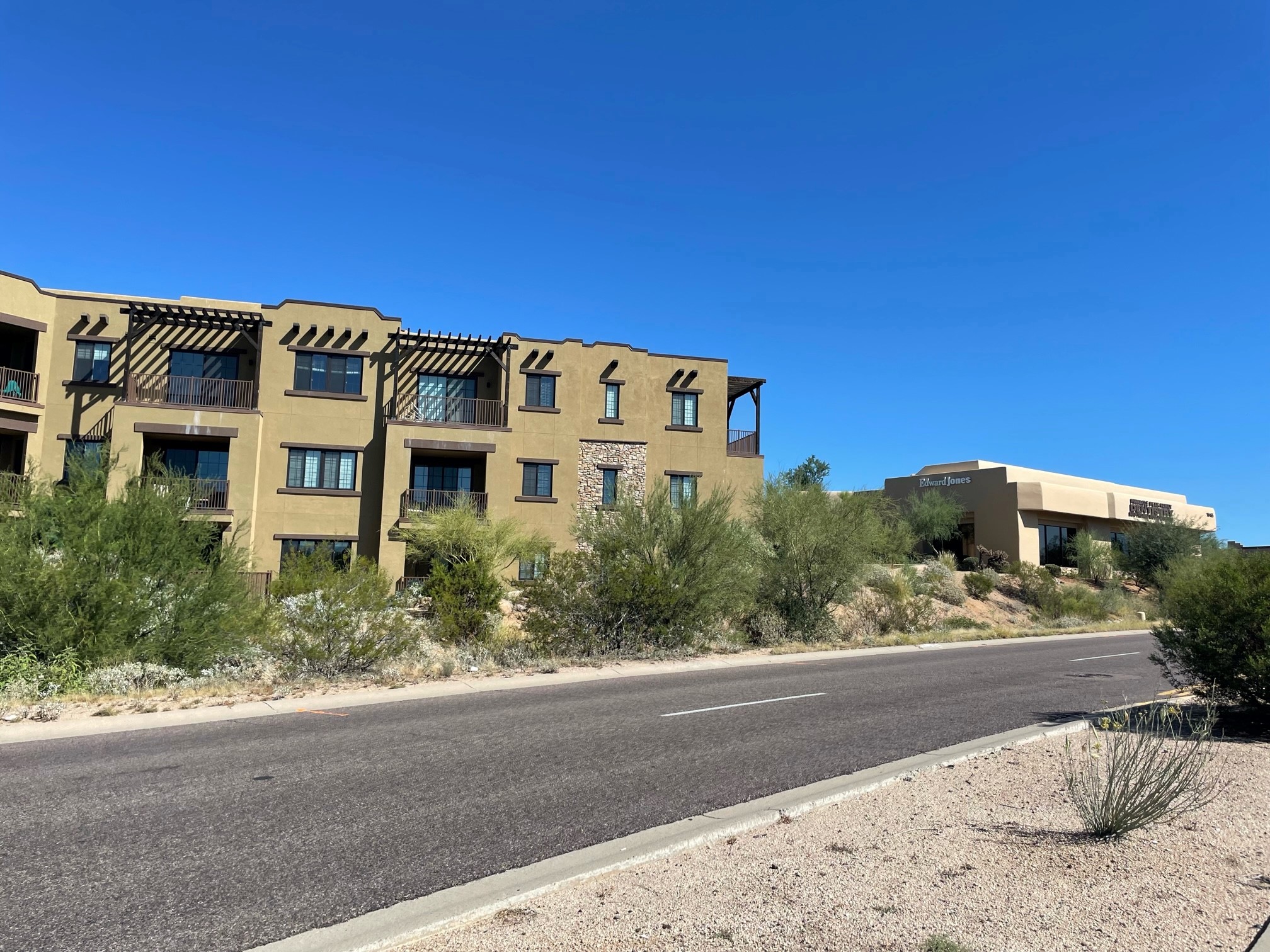
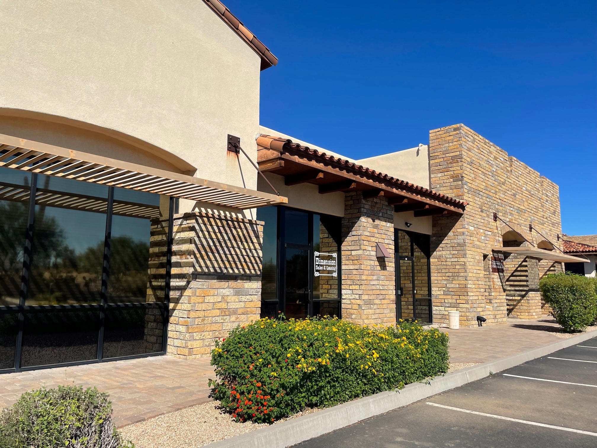
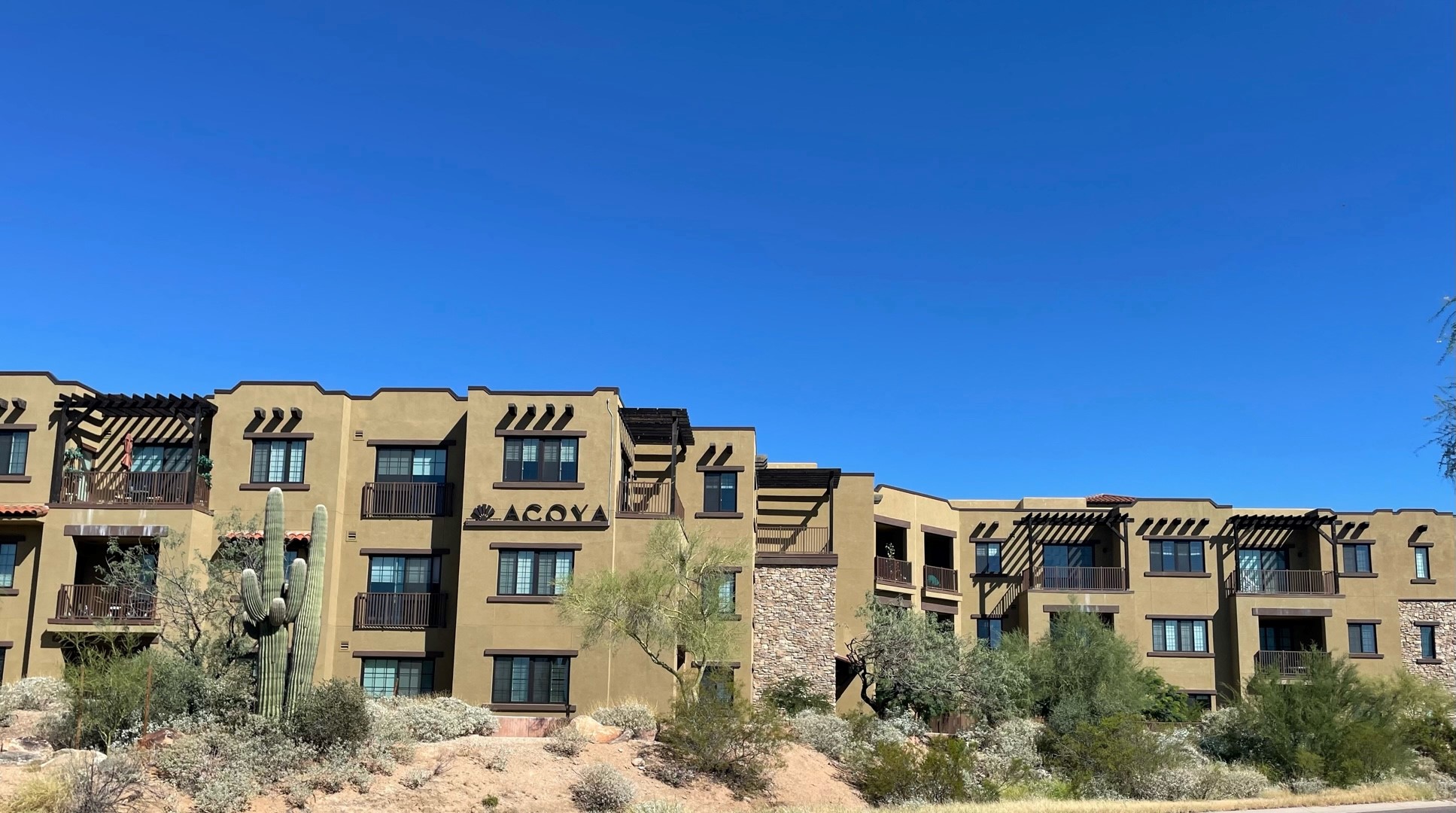
Right – Deep overhangs, pergolas, and covered entryways minimize heat gain in this commercial building in the hot-dry climate.
Image
Image
Right – deeply inset entryways and overhangs provide shade to reduce solar heat entry to this building.
Image
Image
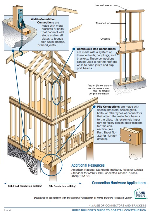
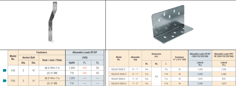
Right – Examples of wall stud to sill plate and foundation and wall rod connectors and brackets.
Image
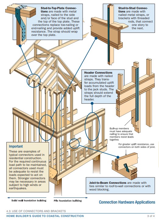
Right – Examples of wall stud to top plate and stud to rim joist framing connectors and brackets.
Image
Right – Furring strips provide a drainage gap between the rigid foam and the siding.
Image
Image
Image
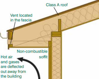
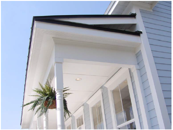
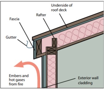
Right – In wildfire prone areas, using a flat soffit with venting on the fascia instead of an angled soffit with down-facing venting reduces the risk of catching rising embers.
Image
Image
Right – Strategically placed trees provide shade to the south-facing windows of this building.
Image
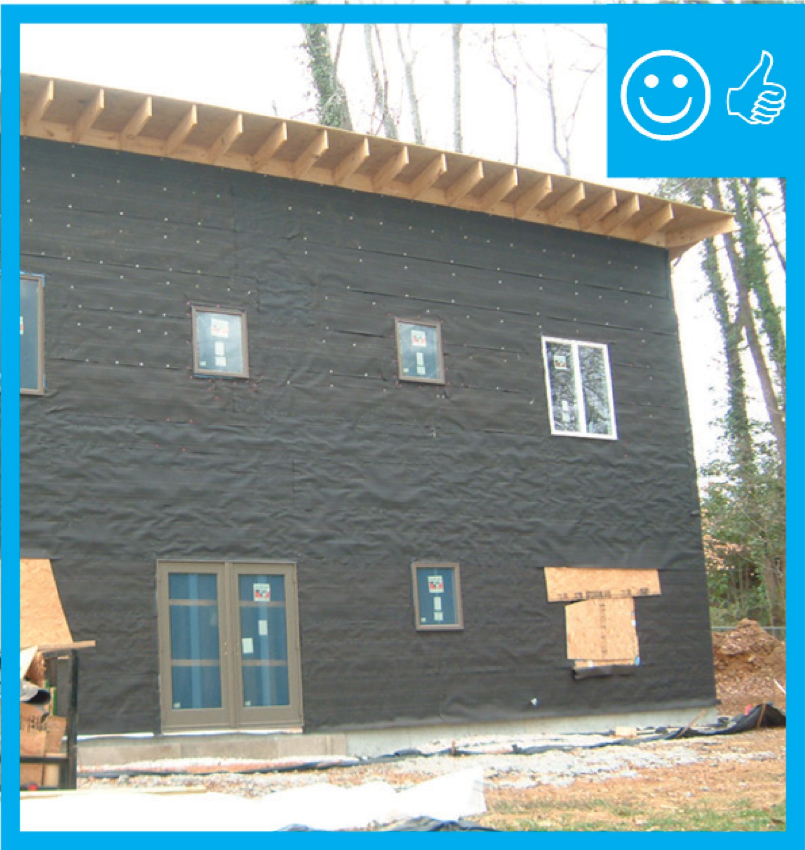
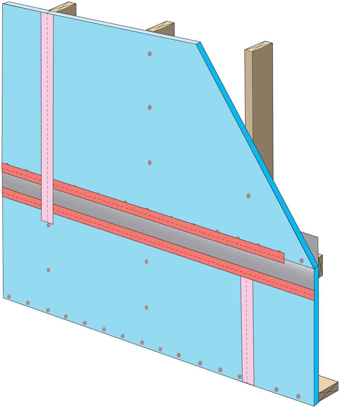
Right – The building felt is installed on all exterior walls and provides a complete drainage system
Image
Right – the building on the right employs light-colored walls, deep tinting, and deeply recessed windows to minimize solar heat gain
Image

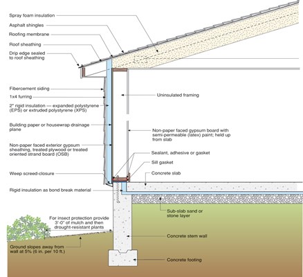
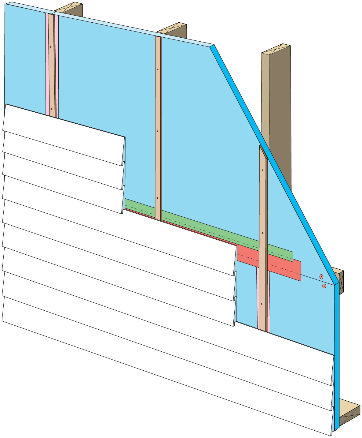
Right – The raised-slab, brick-and-block stem wall, above-grade walls, and roof of this house use flood damage-resistant materials, integrated water, vapor, and air control layers, and construction methods which promote good drainage and rapid drying
Image
Right – The raised-slab, CMU block stem wall, above-grade walls, and roof of this house use flood damage-resistant materials, integrated water, vapor, and air control layers, and construction methods which promote good drainage and rapid drying
Image
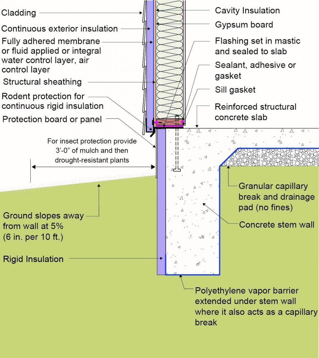
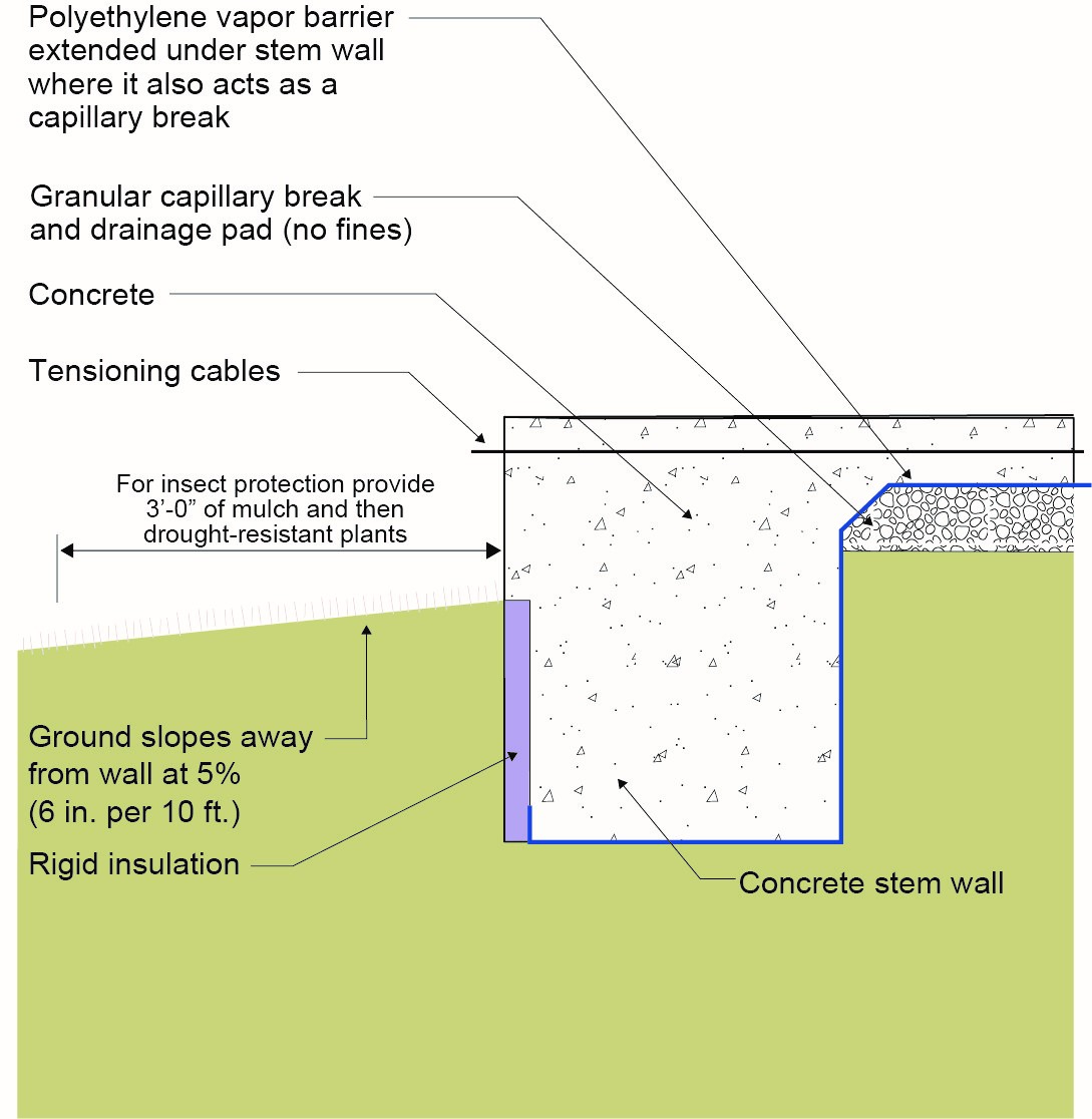
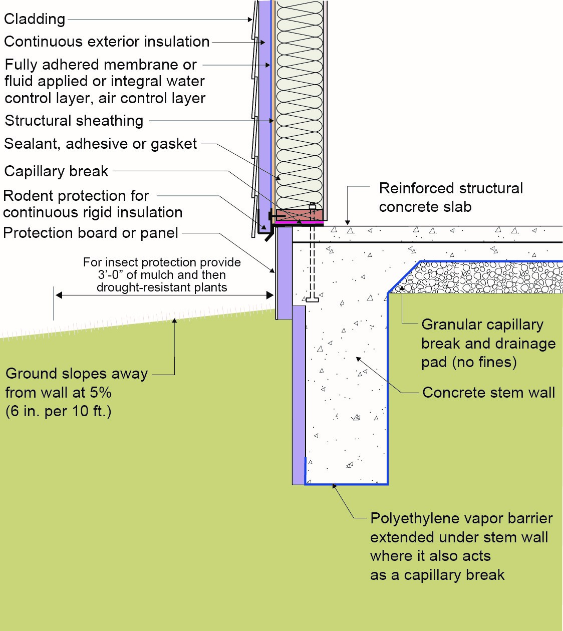
Right – The raised-slab, poured-concrete stem wall, above-grade walls, and roof of this house use flood damage-resistant materials, integrated water, vapor, and air control layers, and construction methods which promote good drainage and rapid drying
Image
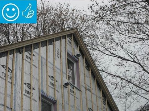
Right – The rigid insulation covers all exterior walls and all seams are taped to provide a complete drainage system
Image
Image
Right – The water-resistant barrier covers the entire house and the seams are taped to provide a complete drainage system
Image
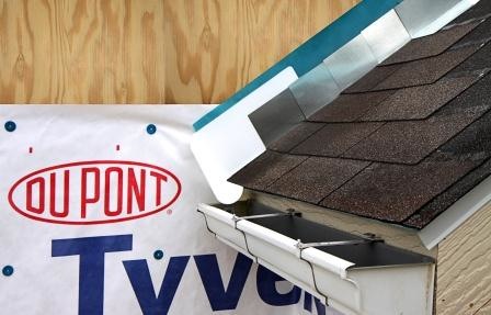
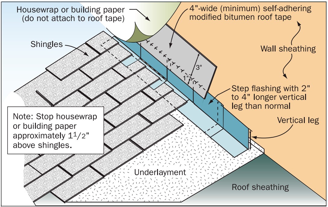
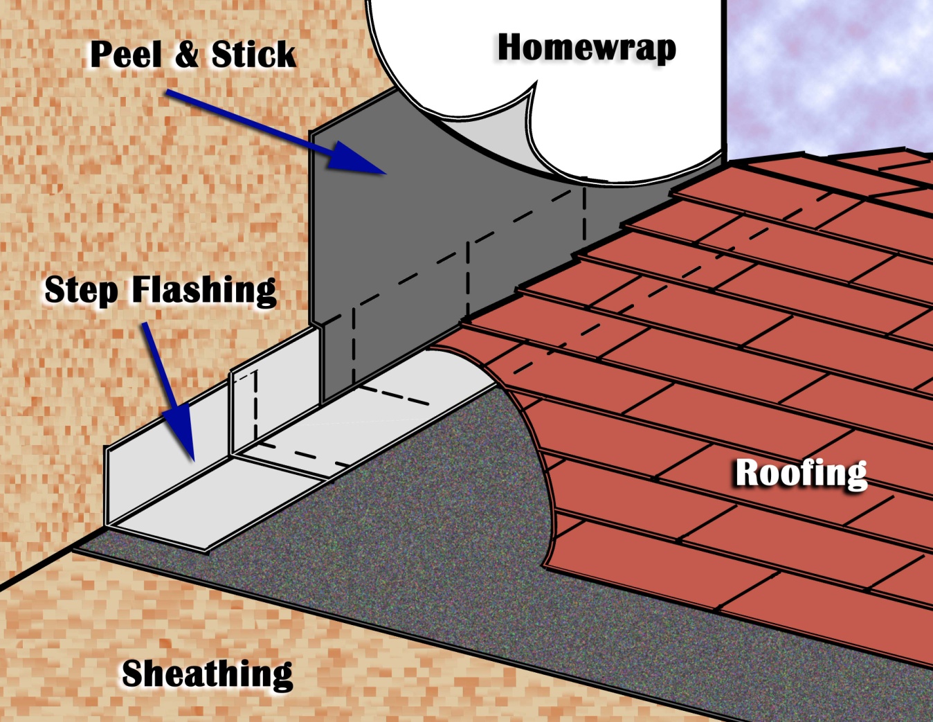
Right – The water-resistant barrier is layered over the step flashing to provide a complete drainage system
Image
Right – There is a self-sealing bituminous membrane installed at the valley of the roof prior to the roof felt
Image
Right – thermal mass walls, small windows, and recessed porch and trees on the south side of this southwest home help to minimize solar heat gain.
Image
Right – this commercial building employs good techniques to resist solar heat gain: awnings and pergolas over windows, recessed windows and entryways, deep tinting on glass, and shade plants.
Image
Right – This fire-rated wall assembly uses exterior gypsum board and an exterior siding of fiber-cement or metal to increase fire resistance.
Image
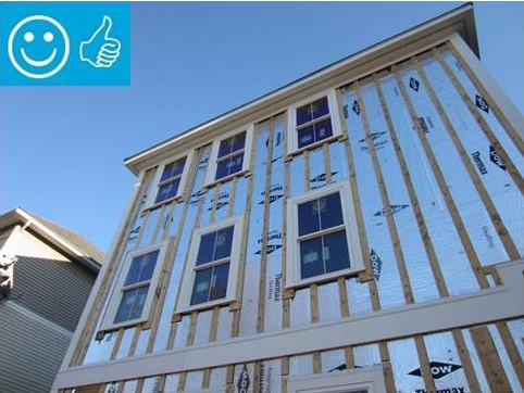
Right – This foil-faced foam sheathing has taped seams and proper flashing details so it can serve as a drainage plane.
Image
Right – This home uses a light-colored exterior wall to reduce solar heat gain
Image
Image
Right – This home uses light tan stucco and white trim to reduce solar heat gain.
Image
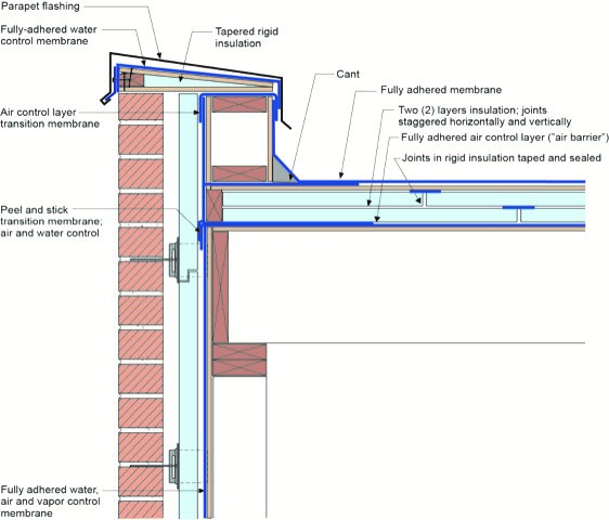
Right – This low-slope roof and parapet assembly has continuity of both the air and water barriers
Image
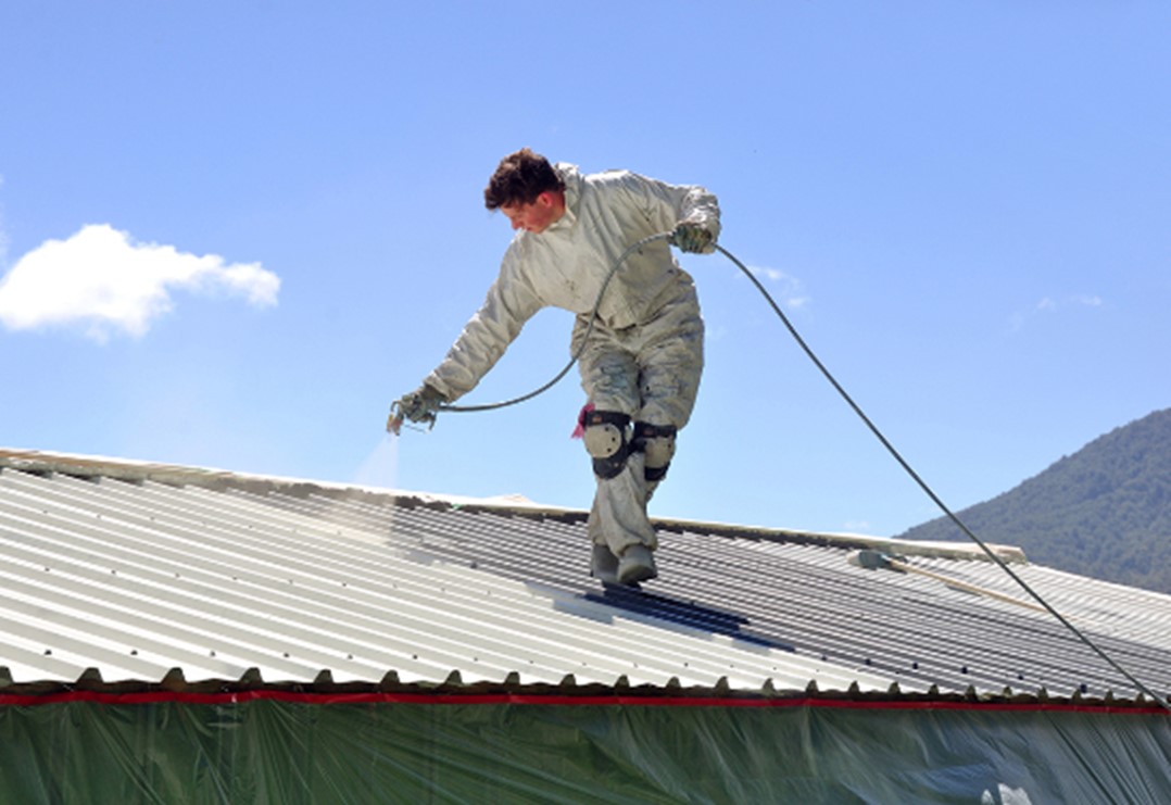
Right – This metal roof is being coated with a cool (high SRI) coating to reduce solar heat gain
Image
Right- Landscaping shades the entry on the south west corner of this hot dry climate building.
Image
Right- This house uses CMU construction for flood and termite resistance as well as thermal mass
Image
Rigid foam insulation can serve as the drainage plane when all seams are taped. Furring strips provide an air gap behind the cladding.
Image
Image
Image
Image
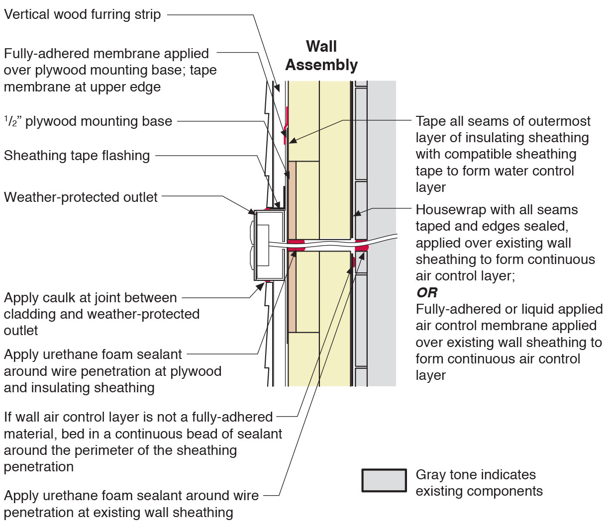
Section view of electric box installation in exterior wall showing flashing and air sealing details
Image
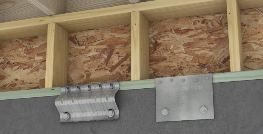
Shear Strength Comparison Between a Foundation Stud Anchor (on left) and a Shear Transfer Angle (on right)
Image
Image
Sources of heat gain in a house include solar gains, infiltration, conduction through walls and roof, occupants, and internal equipment
Image
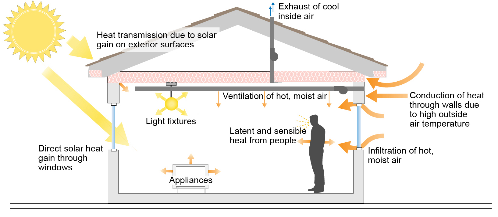
Sources of heat gain in a house include solar gains, infiltration, conduction through walls and roof, occupants, and internal equipment
Image
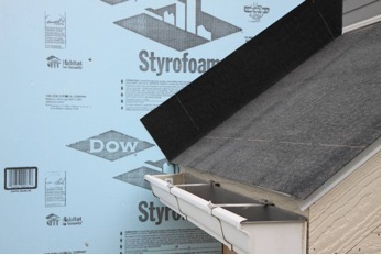
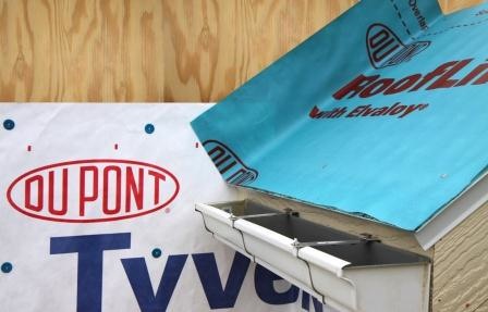
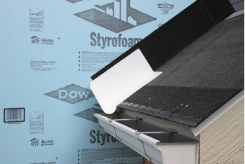
Step 1. Apply roof underlayment over roof deck and up the sidewall over the rigid foam insulation
Image
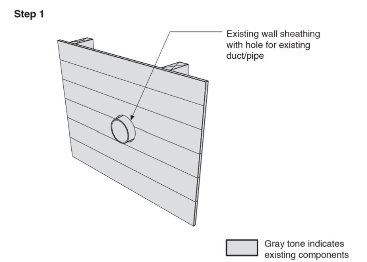
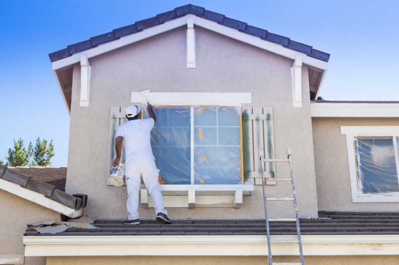
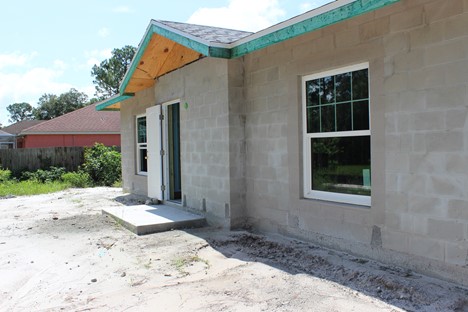
Step 1. Remove the existing wall cladding to prepare to retrofit an exterior wall.
Image
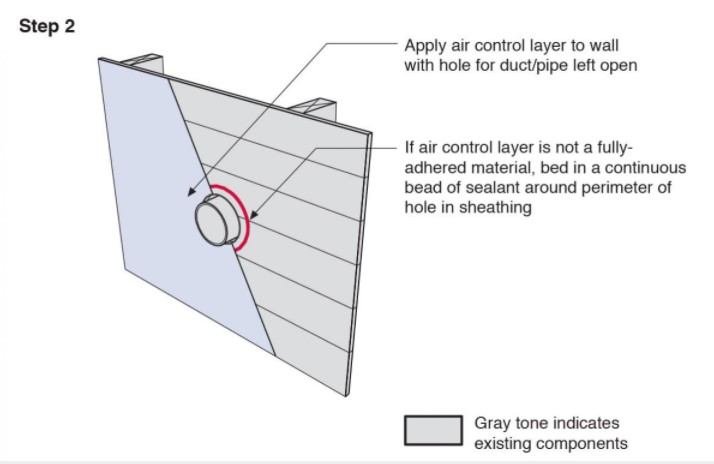
Step 2. Install a continuous air and water control layer over the existing wall sheathing.
Image
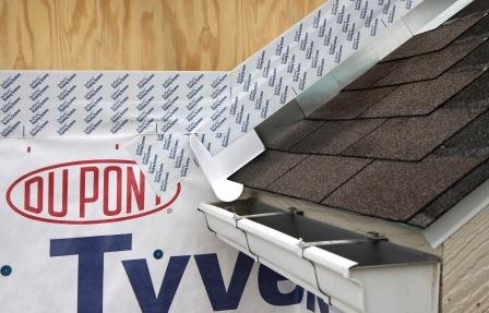
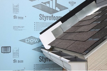
Step 2. Install shingle starter strip then kick-out diverter as first piece of step flashing.
Image
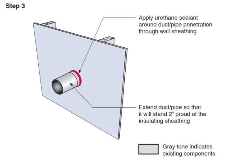
Step 3. Apply urethane sealant around the duct or pipe in the retrofitted exterior wall.
Image
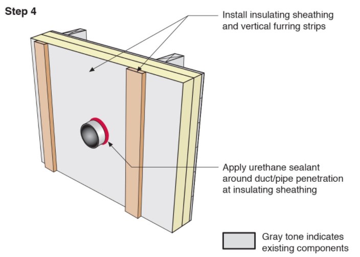
Step 4. Install insulating sheathing and vertical furring strips on the retrofitted exterior wall; seal around pipe or duct with urethane sealant.
Image
Step 4. Install remaining sidewall flashing, appropriate counter flashing, and shingles
Image
Step 5. Apply self-adhesive flashing over top edge of the wall flashing, diverter, and rigid foam insulation
Image
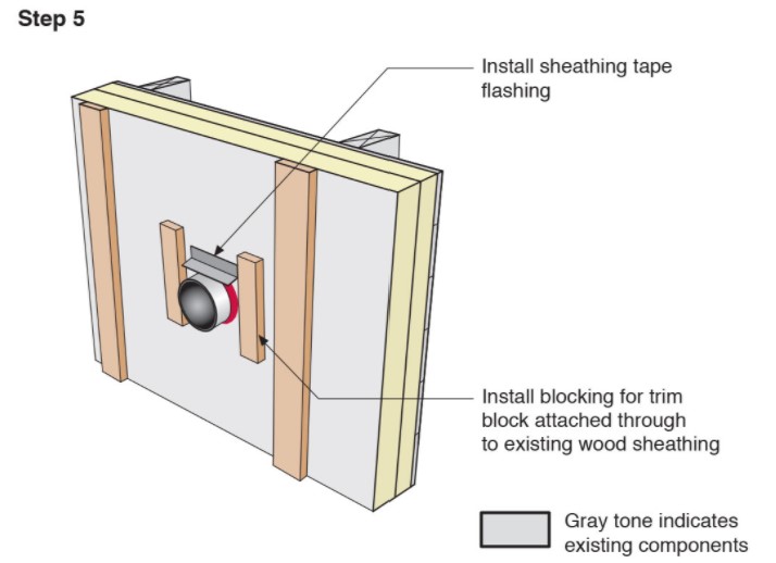
Step 5. Install sheathing tape flashing over the duct or pipe and wood blocking on either side for later attachment of trim.
Image
Image
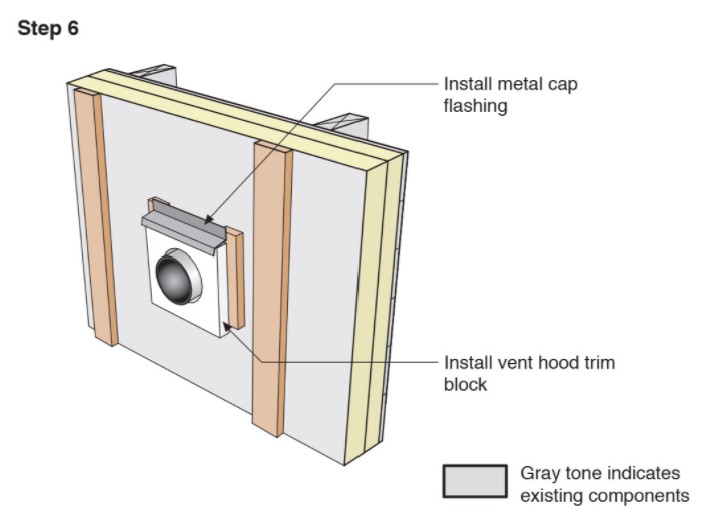
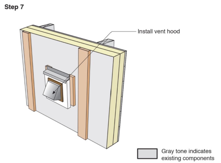
Step 6. Install vent hood trim block, metal cap flashing; seal top edge of flashing with sheathing tape.
Image
Image
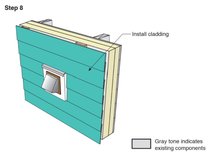
Step 8. Attach the new cladding to the furring strips over the rigid foam for the exterior wall retrofit.
Image

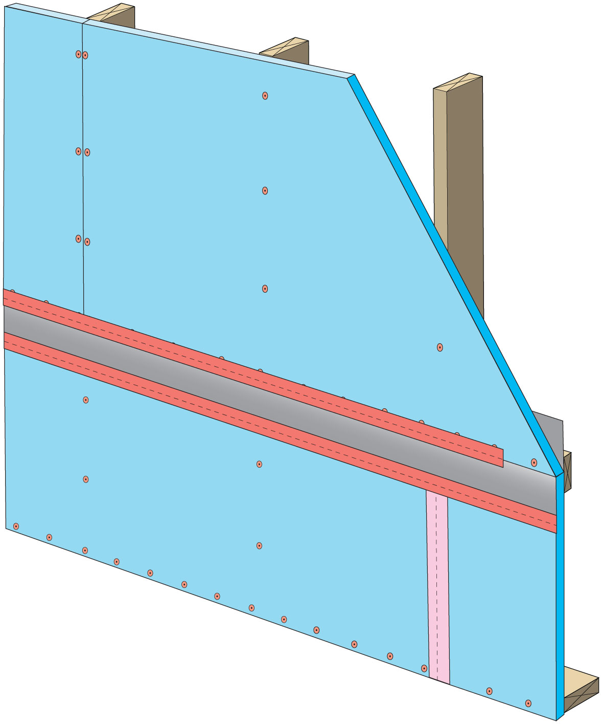
Tape horizontal joint with minimum 3" wide tape placing tape offset high on the joint, adhearing to the upper sheet without wrinkles
Image
Tape the joint between the top insulation sheet and the Z-flashing with 2" wide tape to improve air tightness
Image
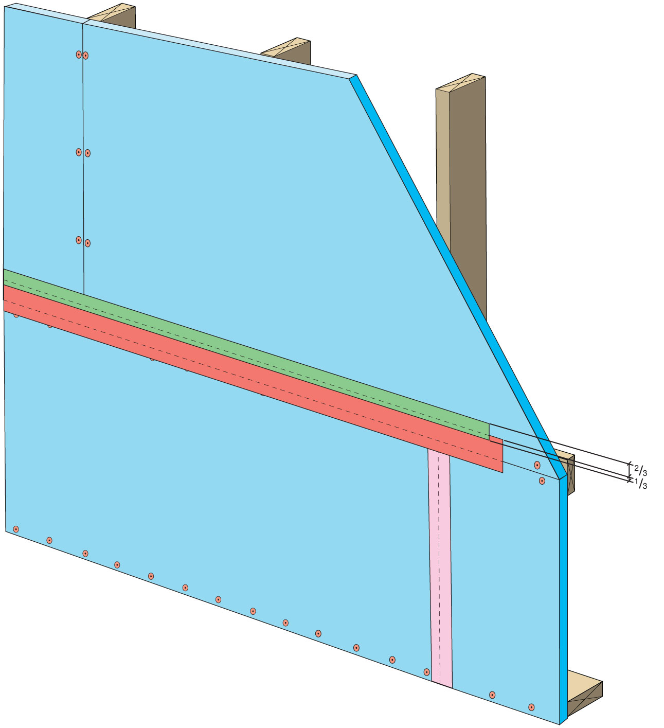
Terminate 4" tape with 2" wide tape placing tape offset high on the joint, 2/3 of the tape should be adhered to the sheet of insulation
Image
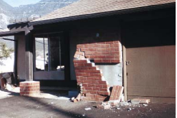
The brick veneer lacked adequate ties to keep the brick from peeling off the wall in an earthquake.
Image
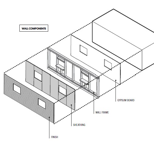
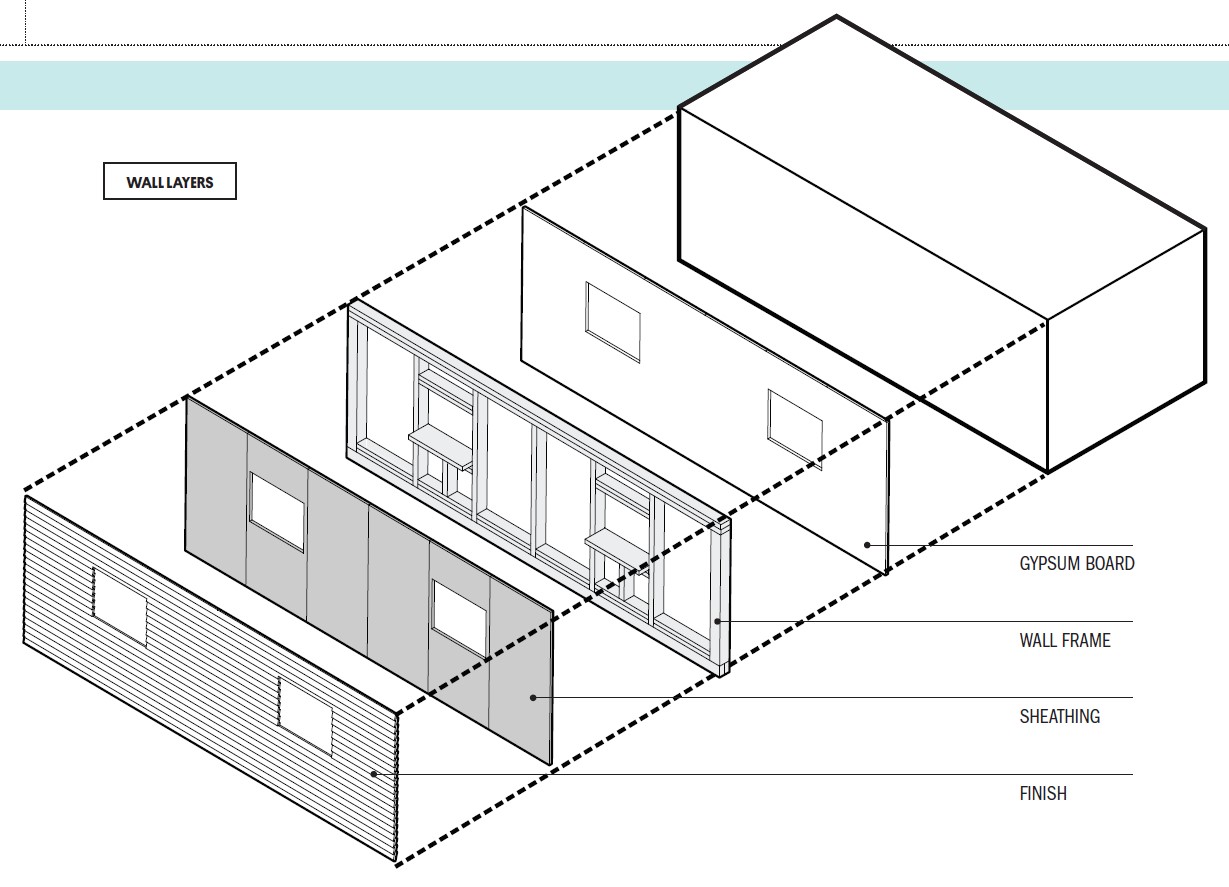
The components of a framed wall include from inside to out: gypsum, wood studs, OSB or plywood sheathing, and siding.
Image

The cripple wall hiding the post-and-pier foundation of this wood framed house toppled when the house was shifted partially off its piers by an earthquake
Image
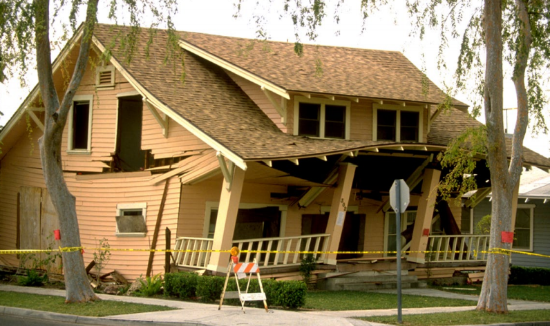
The cripple walls in this home gave way in the 1994 Northridge Earthquake, causing the walls to partially collapse.
Image
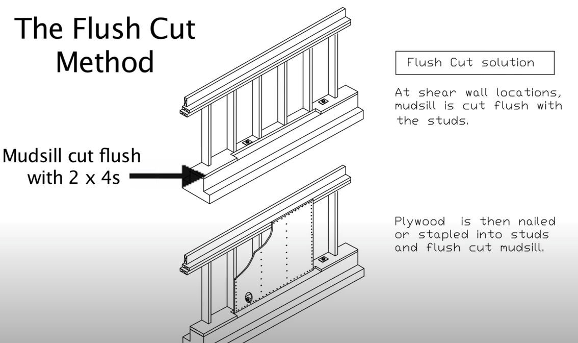
The flush cut method for seismic retrofit bracing of a cripple wall allows the plywood sheathing to be attached directly to both the cripple studs and the notched section of the mudsill
Image
Image
Image
Image
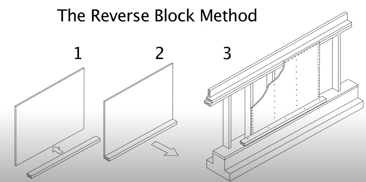
The reverse block method for seismic retrofit bracing of a cripple wall uses a 2x4 attached to the sill plate to provide a means to attach the plywood cripple wall sheathing to the sill plate
Image
The sheathing has rotted because there was not a sufficient drainage gap behind the stucco cladding
Image
Image
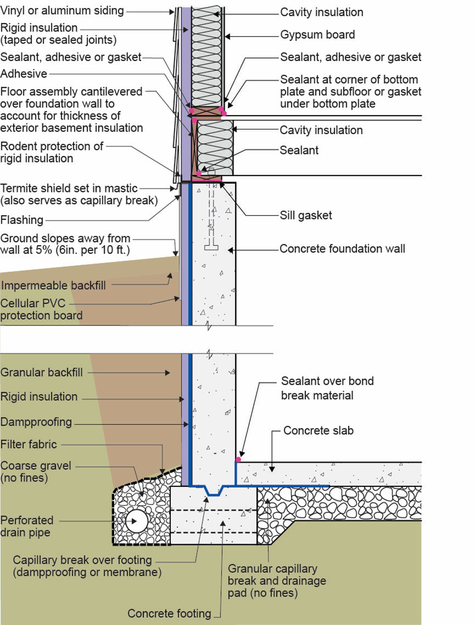
This basement is insulated on the exterior with rigid foam over dampproofing, with granular backfill and footing drains to facilitate drainage away from the foundation, a termite shield to protect from pests, and cellular PVC to protect the rigid foam.
Image
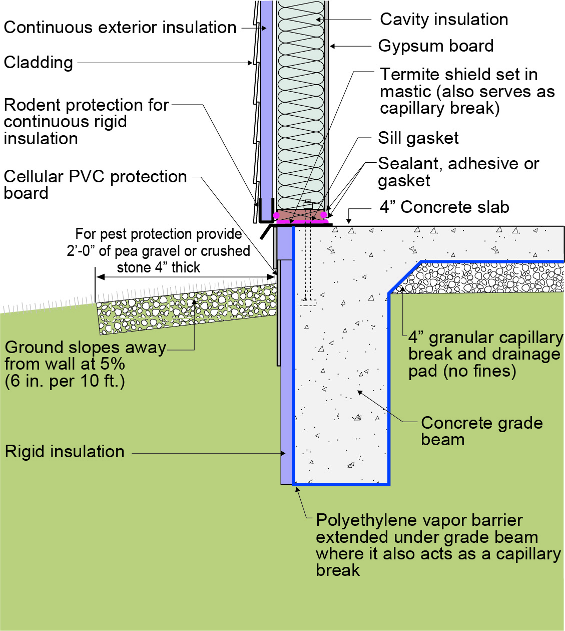
This exterior insulated slab-on-grade monolithic grade beam foundation is protected from pests by termite shield at the sill plate, borate-treated framing, flashing at end of wall insulation, brick veneer over slab-edge insulation, and rock ground cover.
Image
This farmhouse was retrofit by removing the existing siding and adding taped insulated sheathing and battens before installing new siding
Image

This home has heat loss through the roof, leading to ice dam formation and structural issues during winter months.
Image
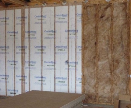
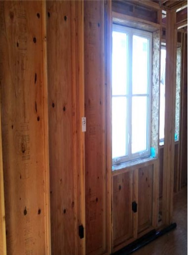
This hot climate zone home uses high quality batt insulation between studs to insulate this connecting garage wall.
Image
This hot climate zone home uses high quality batt insulation to insulate truss-joist headers.
Image
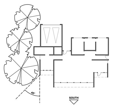
This house is sited so the existing trees will shade the west-facing walls to minimize summertime heat gain
Image
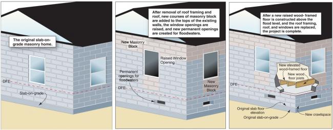
This left-to-right sequence shows the method of wall extension to flood-proof a masonry house on a slab foundation. Here the new, raised floor is wood-framed over a wet-floodproofed crawlspace, but using fill to create a new raised slab is also an option.
Image
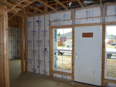
This wall and window assembly has excessive framing around the windows, which can lead to heat gain in how climate zones.
Image
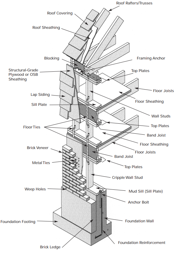
This wood-framed wall is connected with framing anchors, metal strapping and ties, and anchor bolts to secure the roof to the walls and walls to the foundation
Image

Three types of foundation walls: Stem-plus-wood stud cripple wall, reinforced concrete wall, and reinforced concrete block/masonry wall
Image
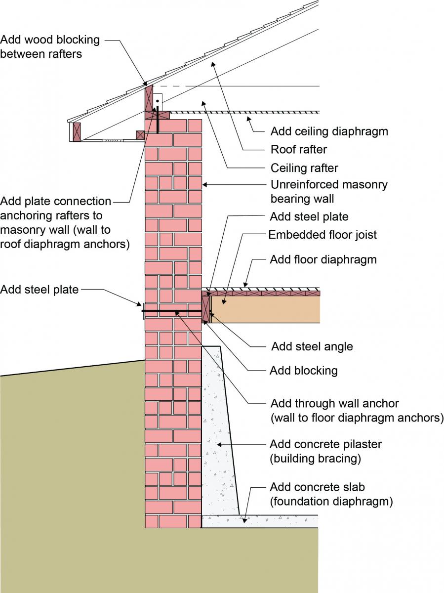
To increase a masonry-walled home’s resistance to seismic forces, solid wood blocking is added between the roof rafters, anchors are added to connect the brick wall to the rafters and floor joists, building diaphragms are added, foundation braced
Image
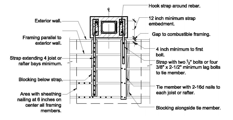
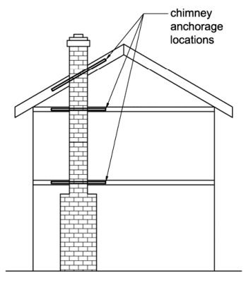
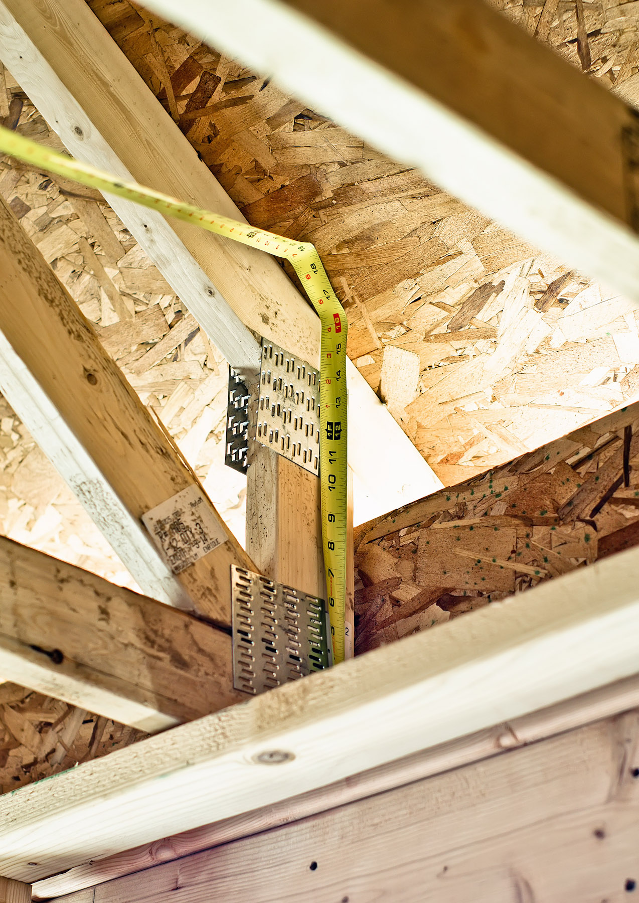
Top view showing how the chimney is attached to at least four ceiling joists running parallel to the exterior wall.
Image
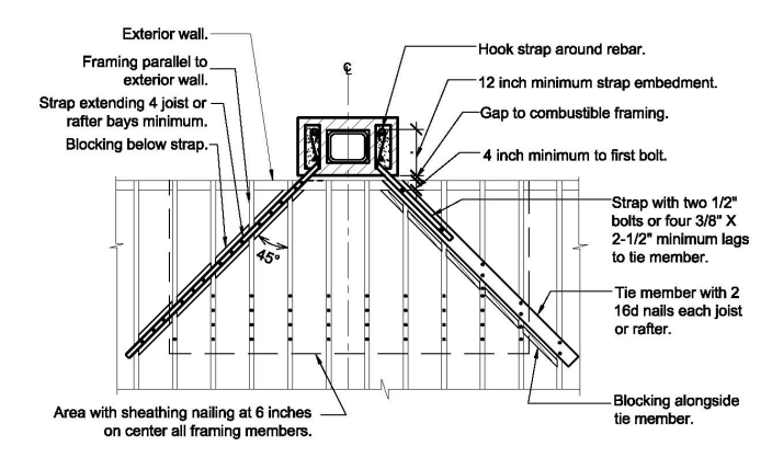
Top view showing how the chimney is attached to ceiling joists that run perpendicular to the exterior wall.
Image
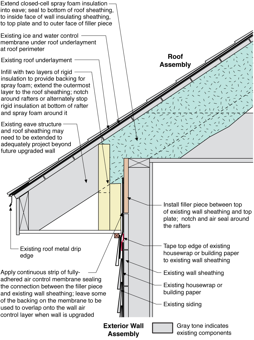
Unvented roof assembly at eave retrofitted with rigid foam, spray foam, and a fully adhered membrane seal at the top of wall-to-roof transition
Image
Image
Image
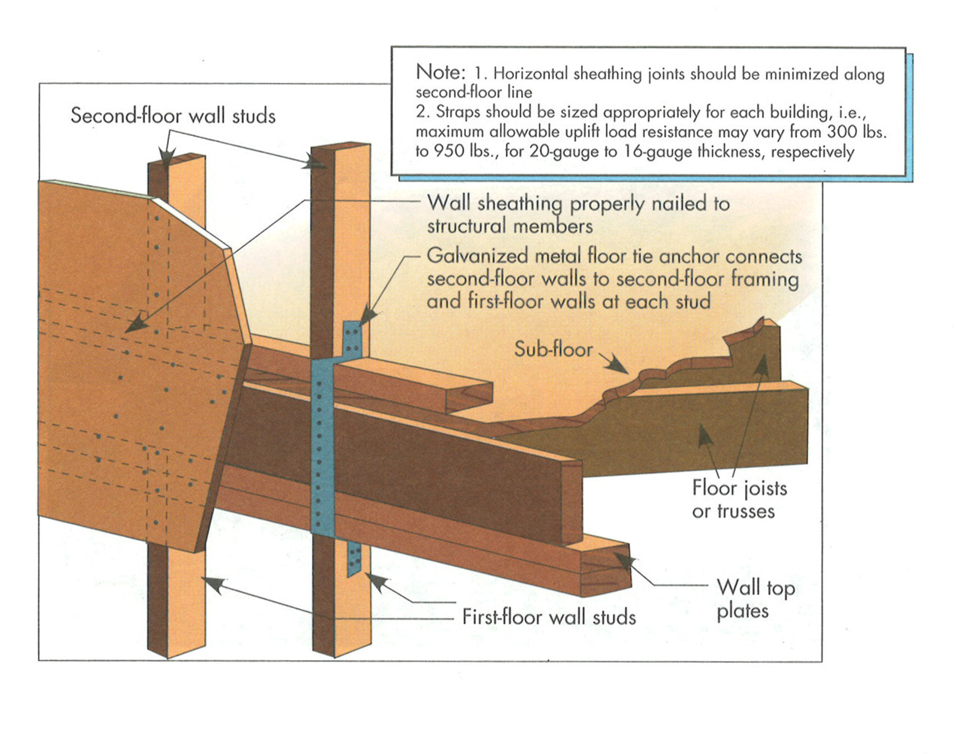
Upper-floor tie to lower floor for two-story building. Floor tie anchor and nailed wall sheathing.
Image
Use a truss joist header assembly as shown here to reduce thermal bridging in hot climate zones.
Image
Image
Image
Using roof and wall materials with a high Solar Reflectance Index (SRI) will reduce heat gains.
Image

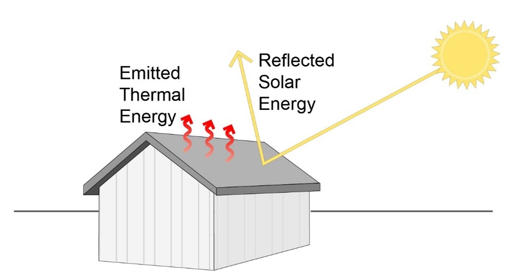
Wall surfaces having high solar reflectance and high thermal emittance will remain cooler when exposed to direct sunlight.
Image
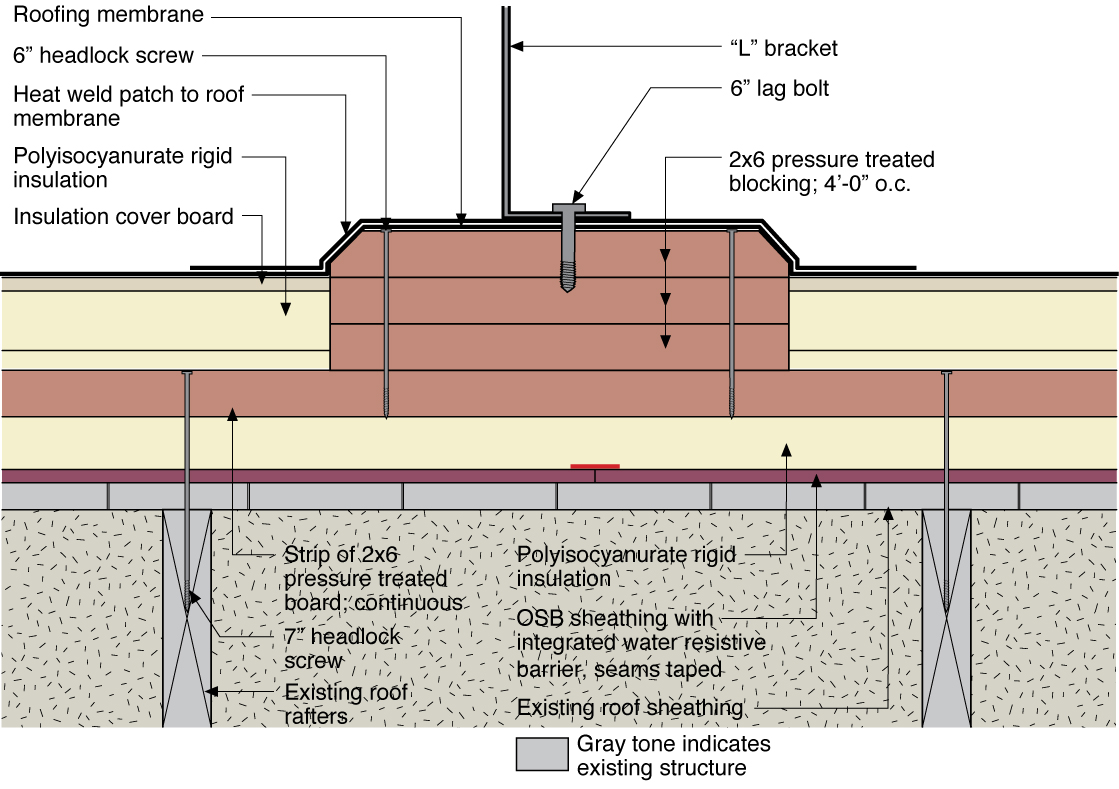
Water management detail for a solar panel rack mounting block installed in rigid foam that was installed over an existing roof
Image
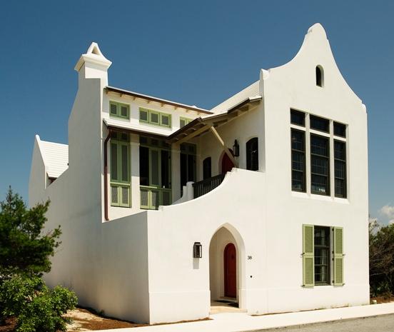
White walls and roofs; overhangs and awnings; and operable shutters and garden walls all help to keep out unwanted solar heat gain providing cool interiors for this Florida home.
Image
Image
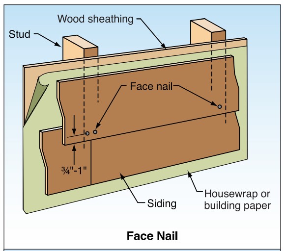
With fiber cement siding, face nail rather than blind nail where the design wind speed is ≥100 mph.
Image
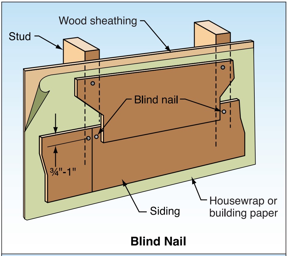
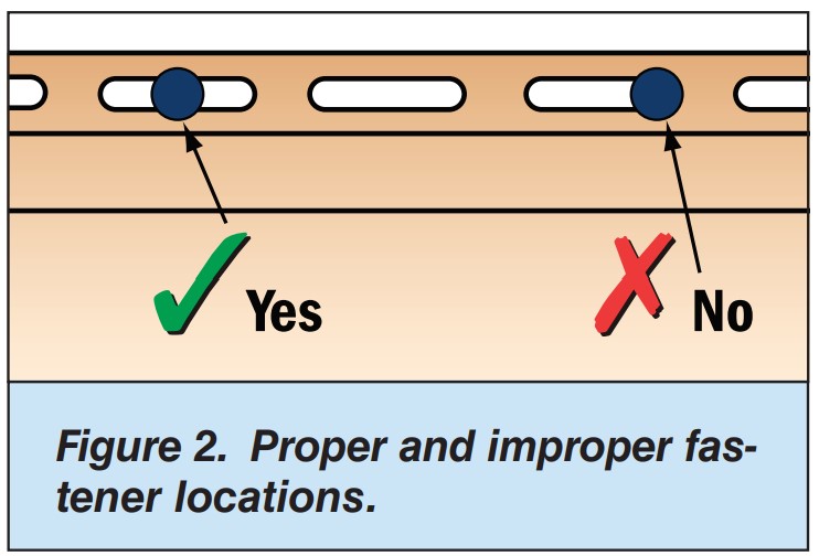
With fiber cement siding, place blind nails 3/4 to 1 inch from top edge and > 3/8 inch in from butt ends.
Image
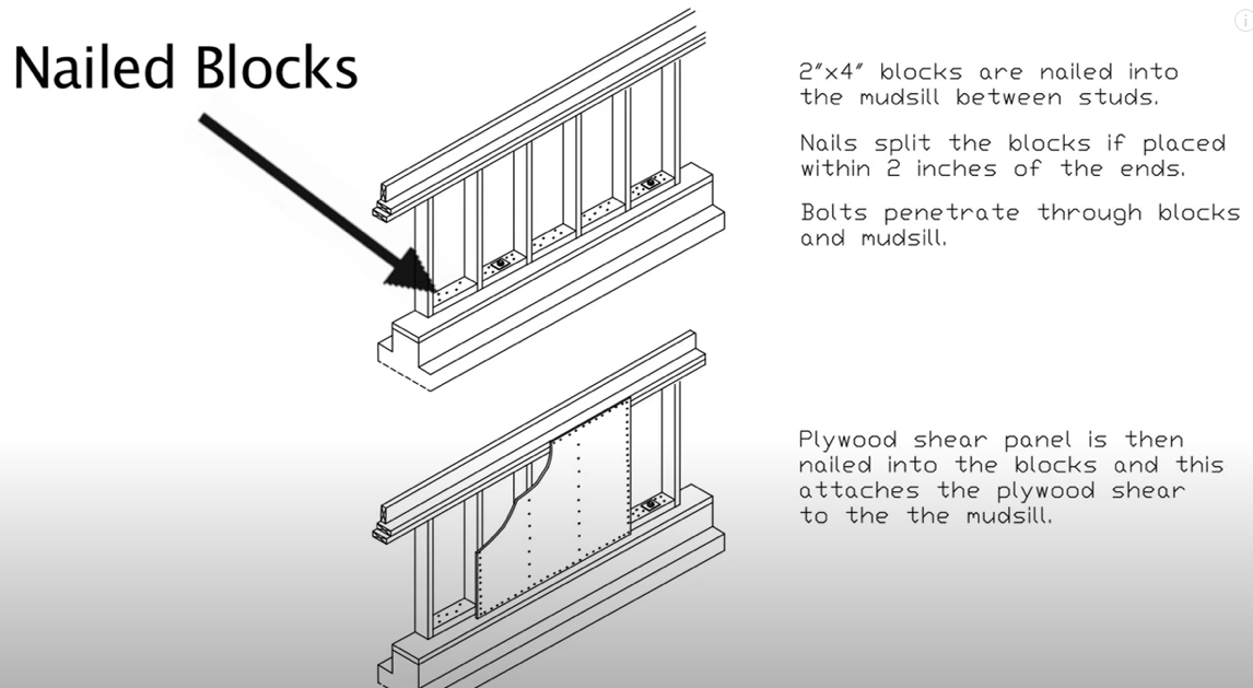
With the nailed block method, wood blocks are attached to the sill plate and the cripple wall plywood is attached to the block to provide shear strength for correctly bracing a cripple wall in a seismic retrofit
Image
Image
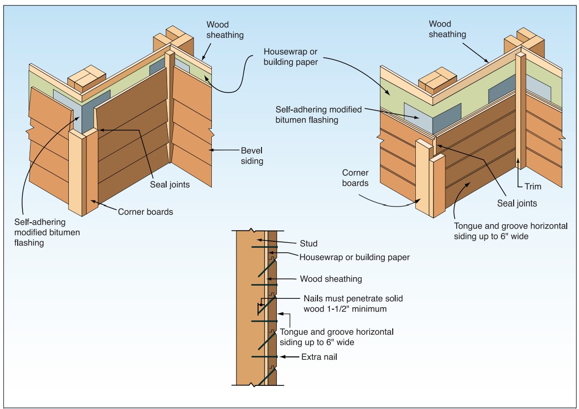
Wood siding installation details to improve resistance to wind-driven rain at corners.
Image
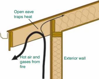
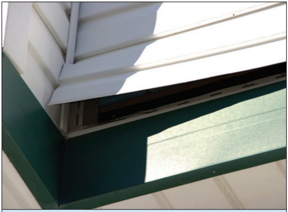
Wrong - An open eave with no soffit covering can trap rising hot air and embers from a wildfire.
Image
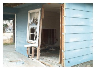
Wrong - During high winds air entered the home elsewhere and pushed out the door which was inadequately anchored to the wall.
Image
Wrong - Framing a dormer using only toe nailing and end nailing is not acceptable in areas subjected to high winds, hurricanes, or earthquakes.
Image
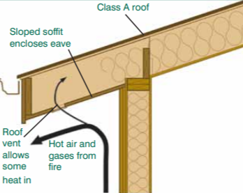
Wrong - If the soffit is applied directly to the rafter eave, it forms a sloping soffit, which creates a pocket that can trap hot air and embers from a wildfire.
Image
Wrong - this building provides no overhangs, minimal window shading, and clear window glass resulting in high solar heat gain.
Image
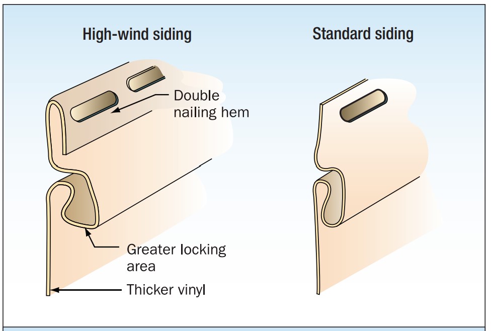
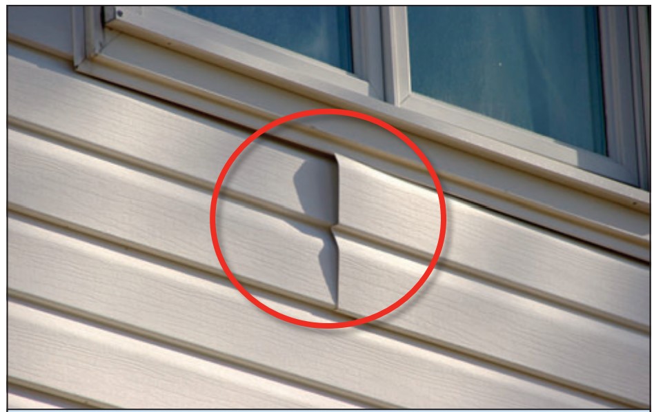
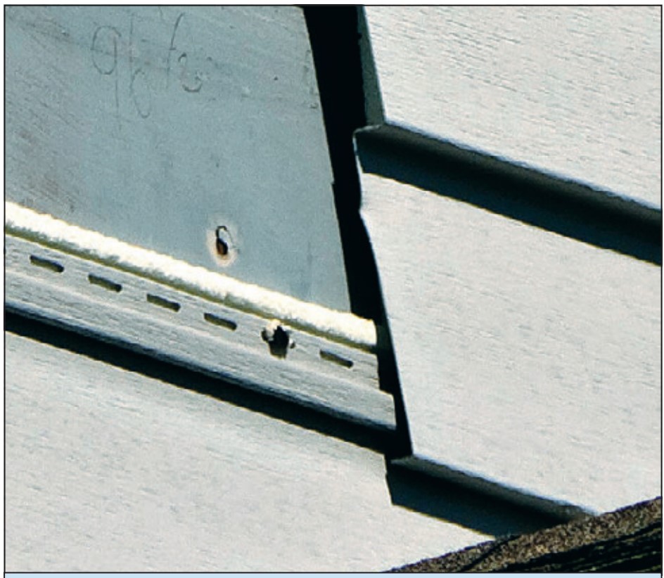
Wrong - Utility trim was substituted for the starter strip and the bottom lock was cut off this vinyl siding so the siding pulled loose under wind pressure.
Image
Wrong – Either this tape was not pressed down firmly or the surface was wet or dirty so the tape is not sticking properly even during construction.
Image
Wrong – For proper detailing of vinyl around windows and other obstacles, use utility trim, punch snaplocks into siding, and do not overlap directly beneath a window.
Image
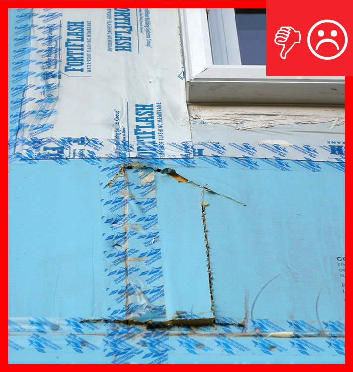
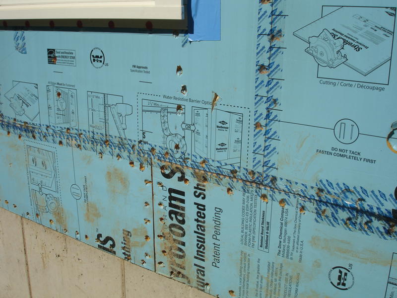
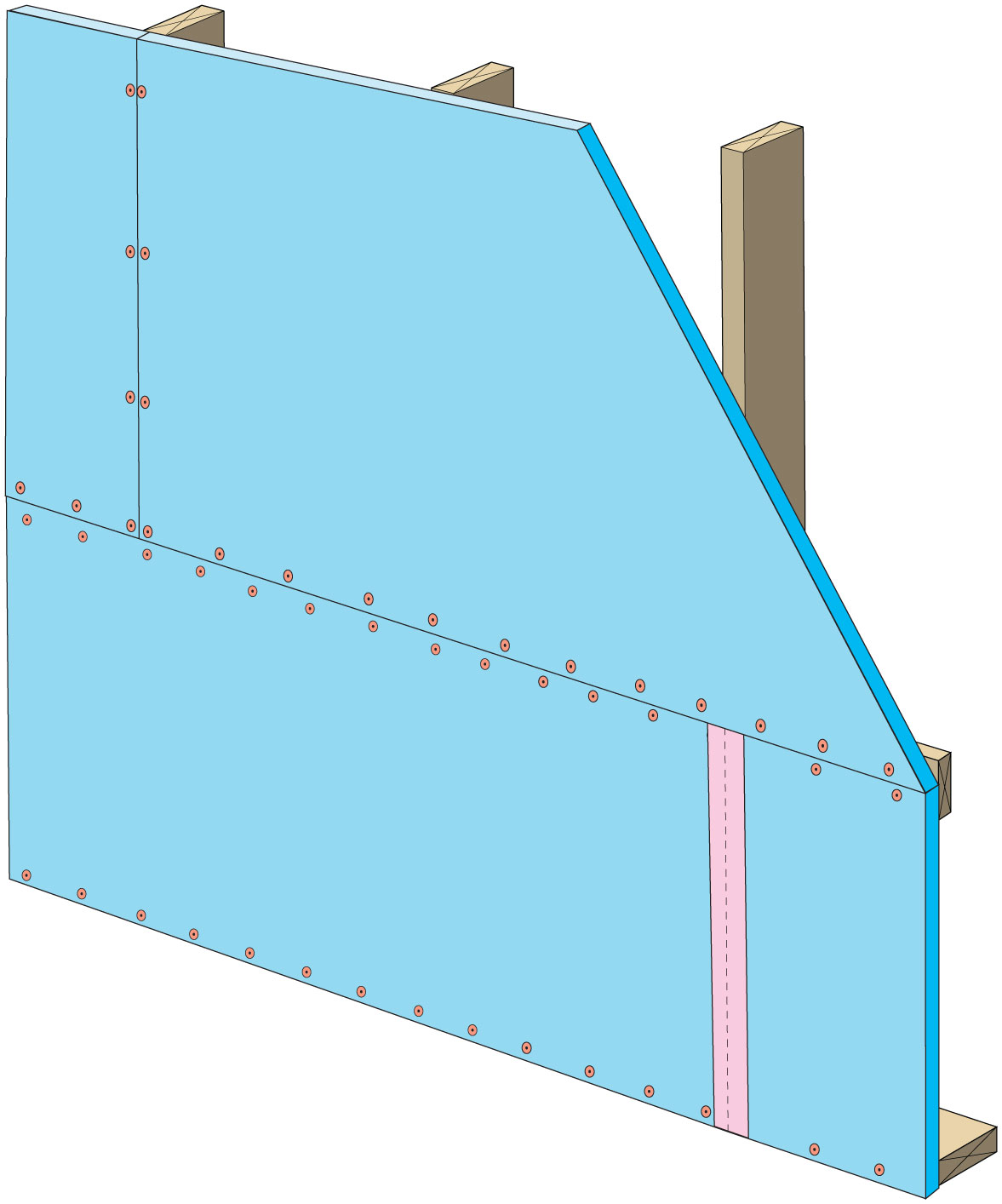
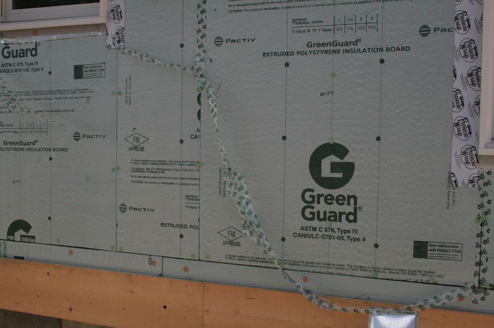
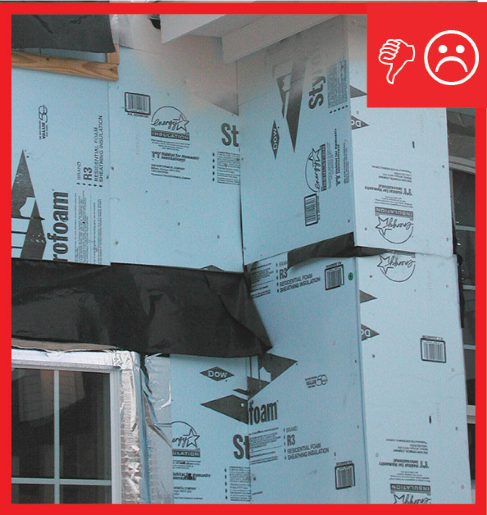
Wrong – If the insulated sheathing will serve as an air barrier and drainage plane, any cuts and seams must be taped or sealed.
Image
Wrong – Misalignment of the tie reduces the embedment and enables the brick veneer to be pulled away.
Image
Image
Wrong – The rigid sheathing seams are not taped and the gaps could cause moisture problems
Image

Wrong – The roof sheathing was inadequately fastened and gave way causing the gable end wall to fail
Image

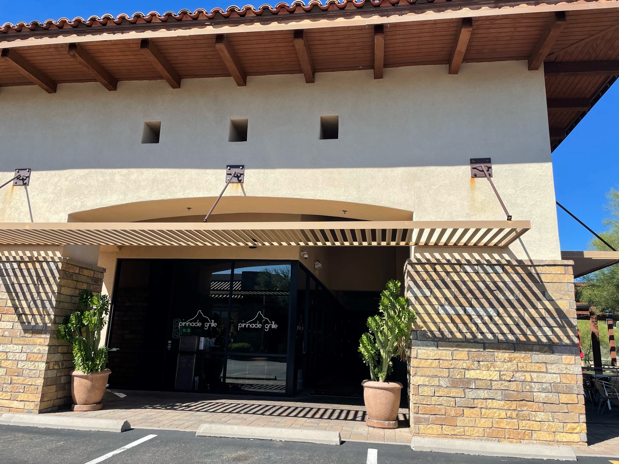
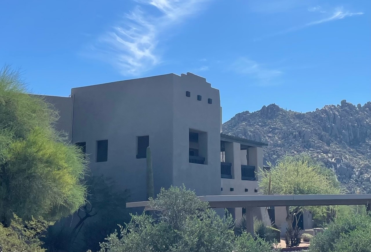
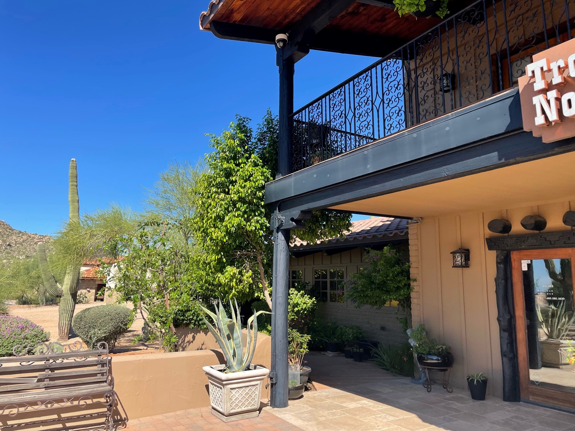
Wrong – The south side of this building in Arizona has very little architectural or landscape shading to block solar heat gain.
Image
Image
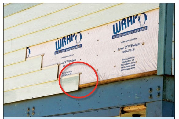
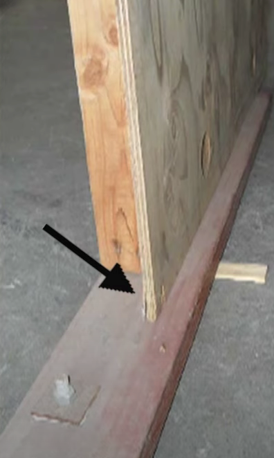
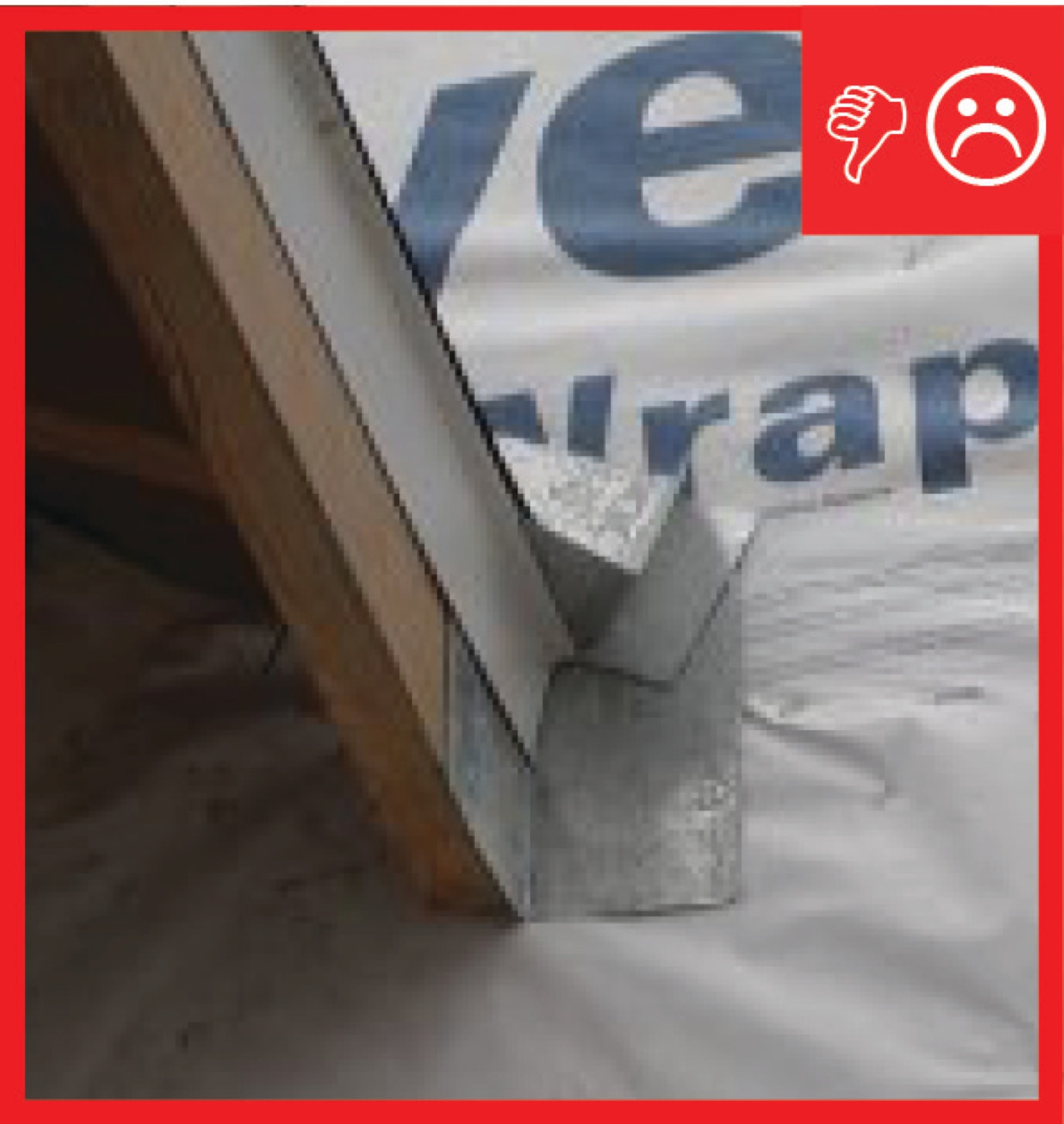
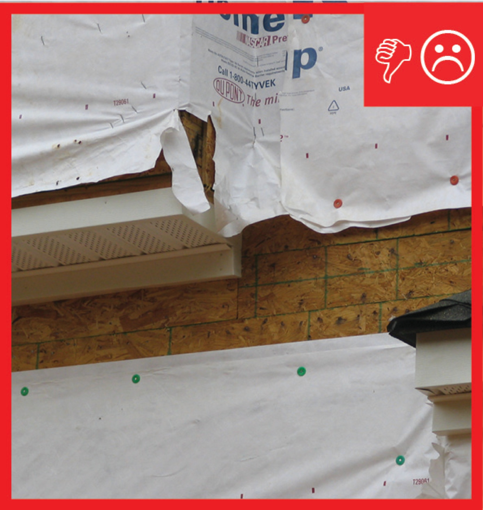
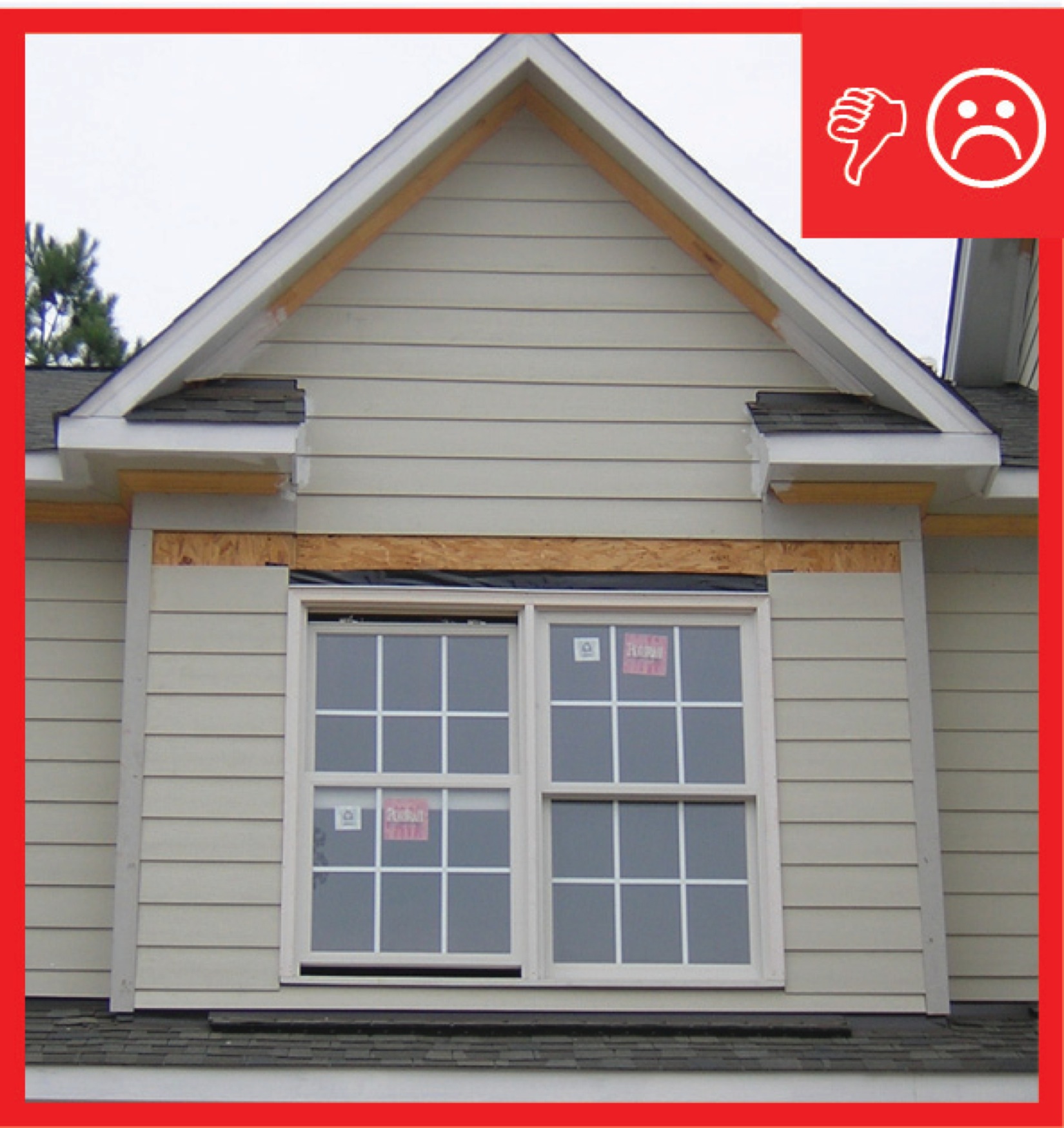
Wrong – The underside of the first course of siding extends beyond the underlying sheathing leaving it vulnerable being pulled off by pressure from high winds.
Image
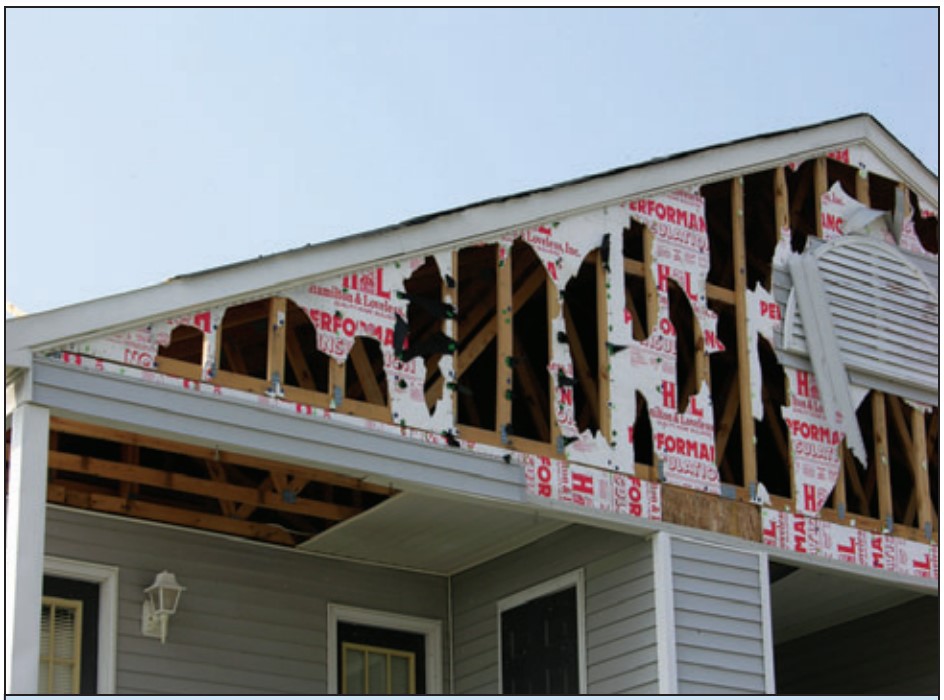
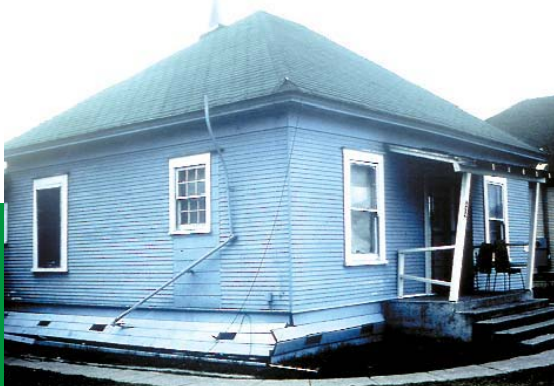
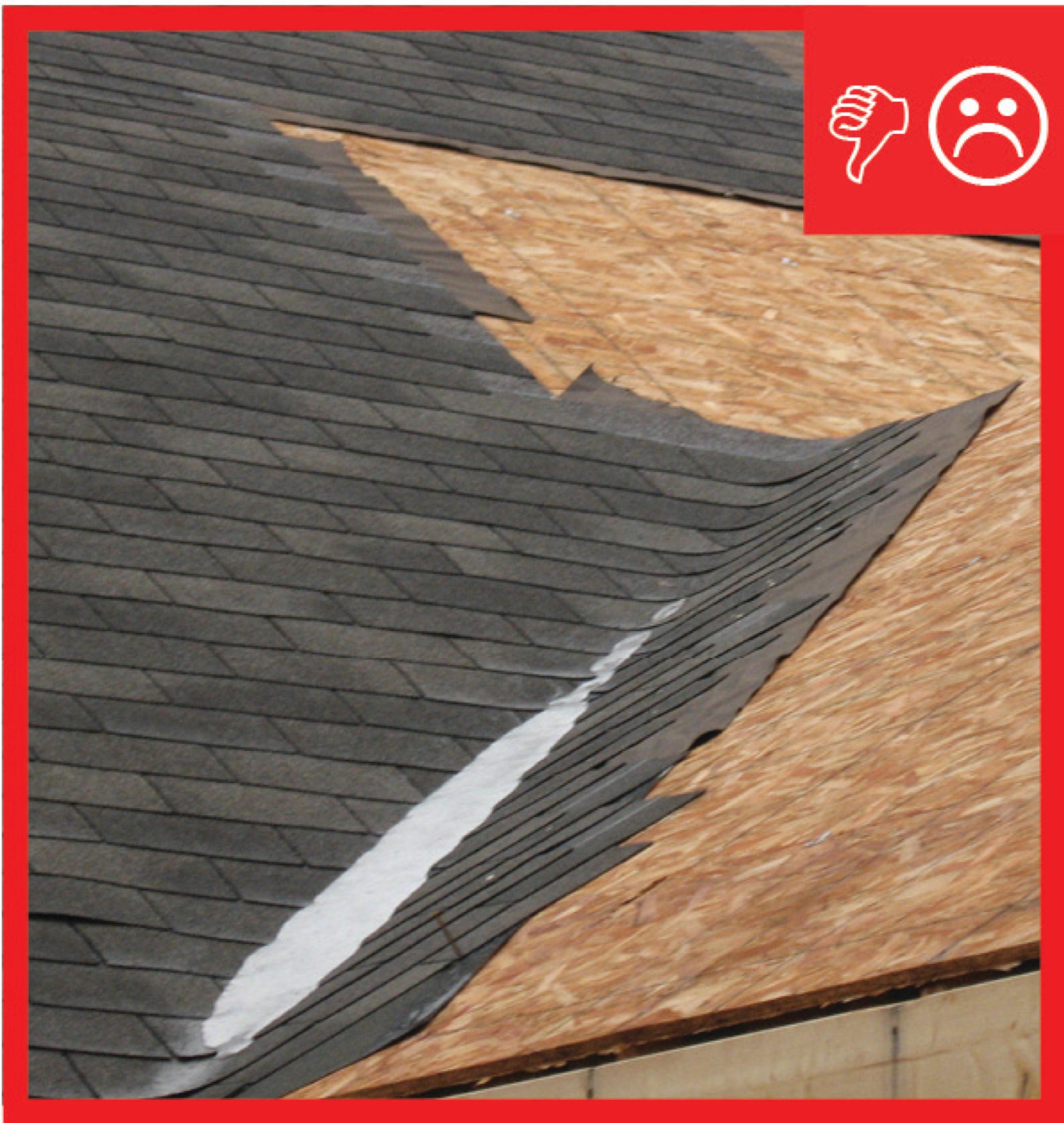
Wrong – The vinyl siding at this gable was installed over rigid foam instead of wood sheathing and neither had the structural strength to resist hurricane wind pressures.
Image
Image
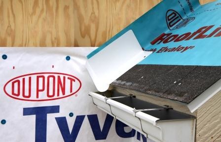
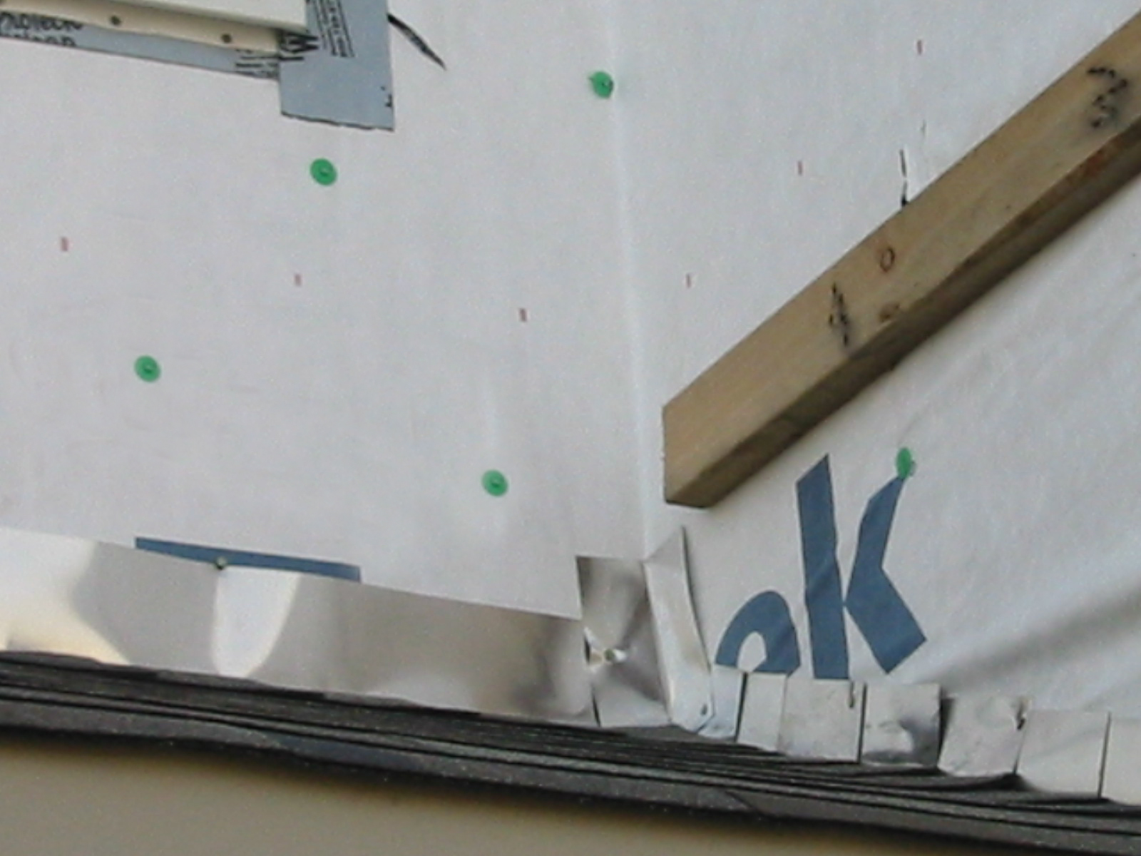
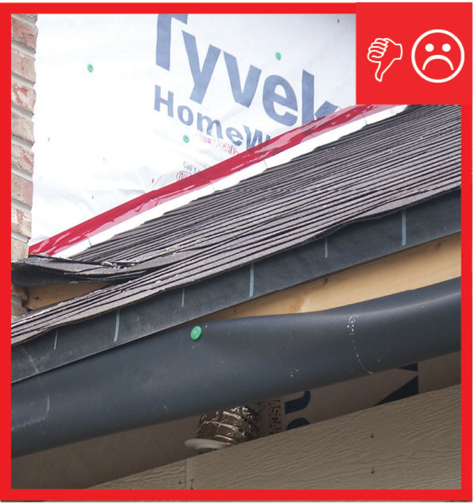
Wrong – the water-resistant barrier is layered underneath the step flashing, which could allow water to get behind the step flashing and into the wall.
Image
Wrong – The water-resistant barrier is not complete and the holes and gaps could cause moisture problems
Image
Wrong – There is not a self-sealing bituminous membrane installed at the valley of the roof
Image
Wrong – There is not a water-resistant barrier installed underneath the exterior finish of the walls