Showing results 1 - 250 of 253
Image
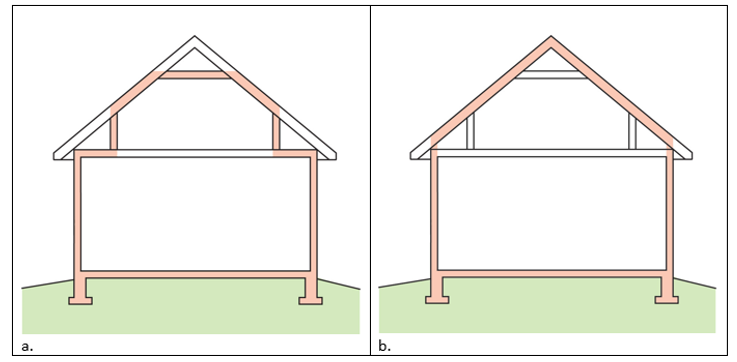
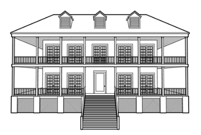
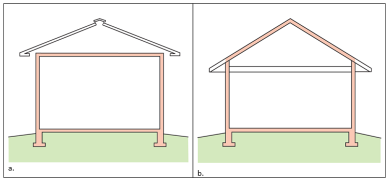
A 1- and ½-story home with a room located in the attic and the thermal boundary located at either a) the walls and ceiling of the attic room with small vented attic spaces or b) the roof line for an unvented attic
Image
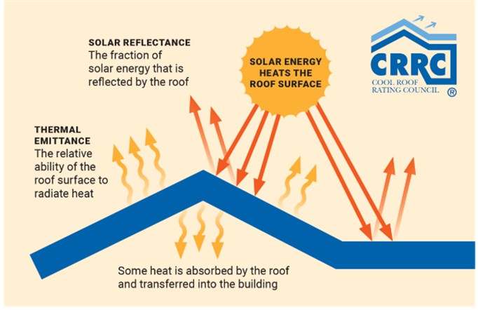
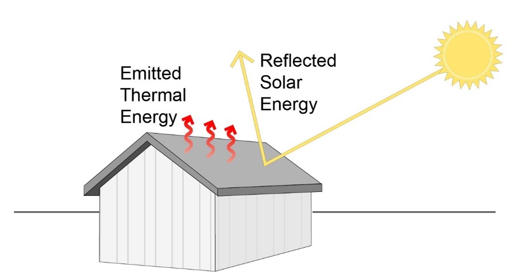
A cool roof utilizes materials with high solar reflectance and thermal emittance to reflect solar energy and reduce heat gain to the home
Image
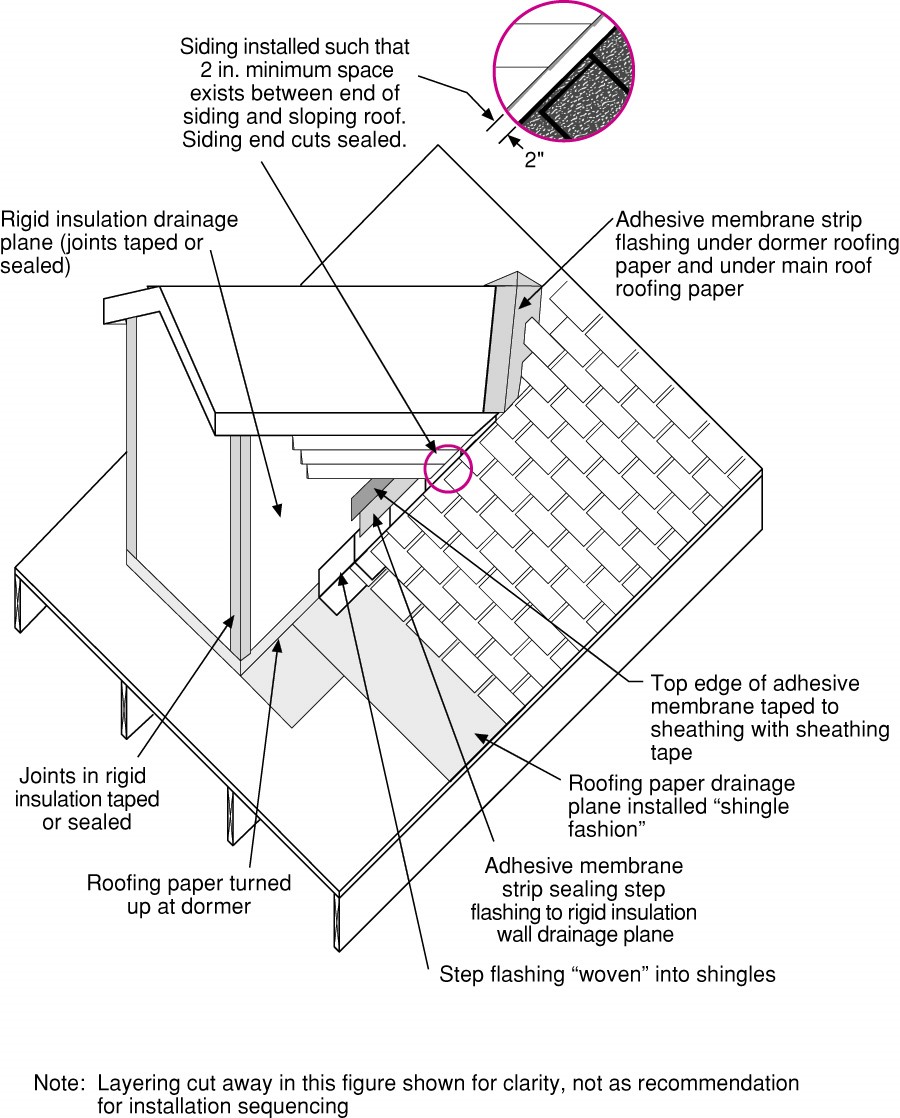
A dormer with an openable window (not shown) can provide access to the roof if flood waters rise too high and too quickly; the dormer should be properly insulated, flashed, and air sealed
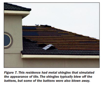
Image
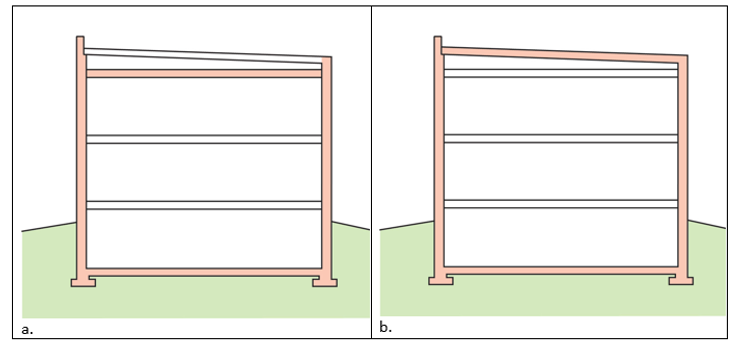
A low-sloped shed roof with the thermal boundary located at either a) the flat ceiling with a vented attic or b) the roof line for an unvented attic
Image
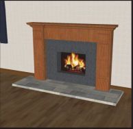
A masonry chimney is reconstructed to withstand seismic forces by adding an insert to the existing firebox
Image
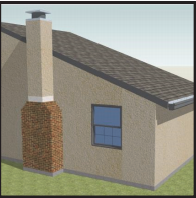
A masonry chimney is reconstructed to withstand seismic forces by completely retrofitting the firebox and chimney using light-frame construction on the top of the foundation
Image
A masonry chimney is reconstructed to withstand seismic forces by maintaining the current firebox but replacing the chimney section with a metal flue and light-weight chimney enclosure.
Image
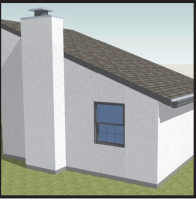
A masonry chimney is shortened and capped at roof level to reduce its chances of detaching in high winds or earthquakes; the fireplace can no longer be used.
Image
Image
Image
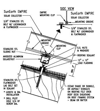
A thermosiphon solar hot water system heats a fluid in the solar collector; the heated fluid heats potable water in a roof top tank.
Image
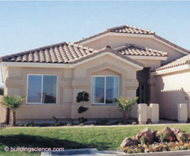
A typical Las Vegas hot-dry climate home made of wood frame construction and insulated with R-25 expanded polystyrene externally over a drainage plane, with an unvented wood frame insulated attic and roof assembly.
Image
Image
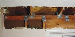
Add metal connectors to strengthen framing connections in an existing wall from inside the home by removing drywall.
Image
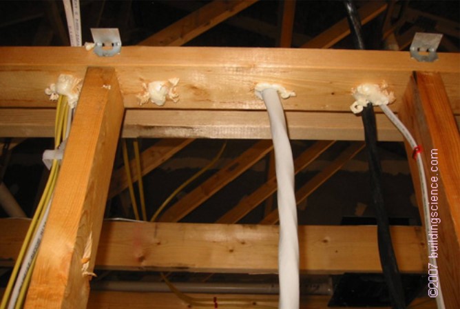
All holes through the top plates should be sealed with canned spray foam to prevent conditioned air from leaking into the attic.
Image
Image
Image
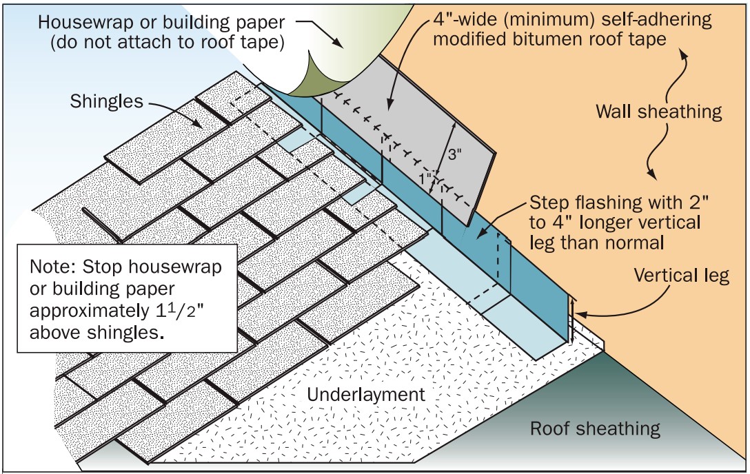
Apply self-adhesive flashing over top edge of the wall flashing, diverter, and housewrap
Image
Image
Attic ventilation can reduce the likelihood of ice dam formation by cooling the roof deck.
Image
Image
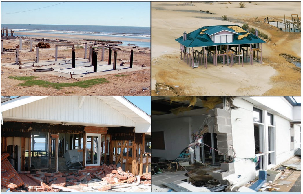
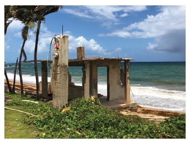
Buildings damaged by a hurricane storm surge: upper homes on gulf shoreline were hit by large waves above the lowest floor, lower left home on bay and right school 1.3 miles from gulf shoreline were hit by surge and small waves.
Image
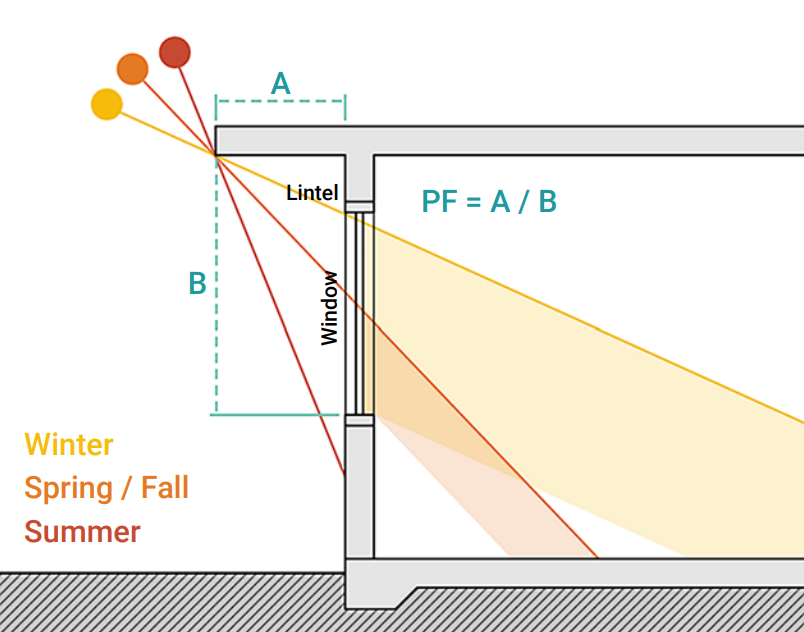
Calculate projection factor (PF) by dividing overhang (A) by length of window (B).
Image
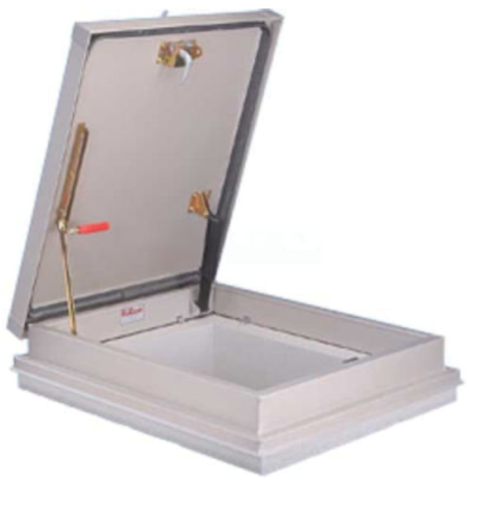
Commercially available “roof hatch” products provide an openable access to the roof for maintenance and emergency egress that meets code dimensional requirements
Image
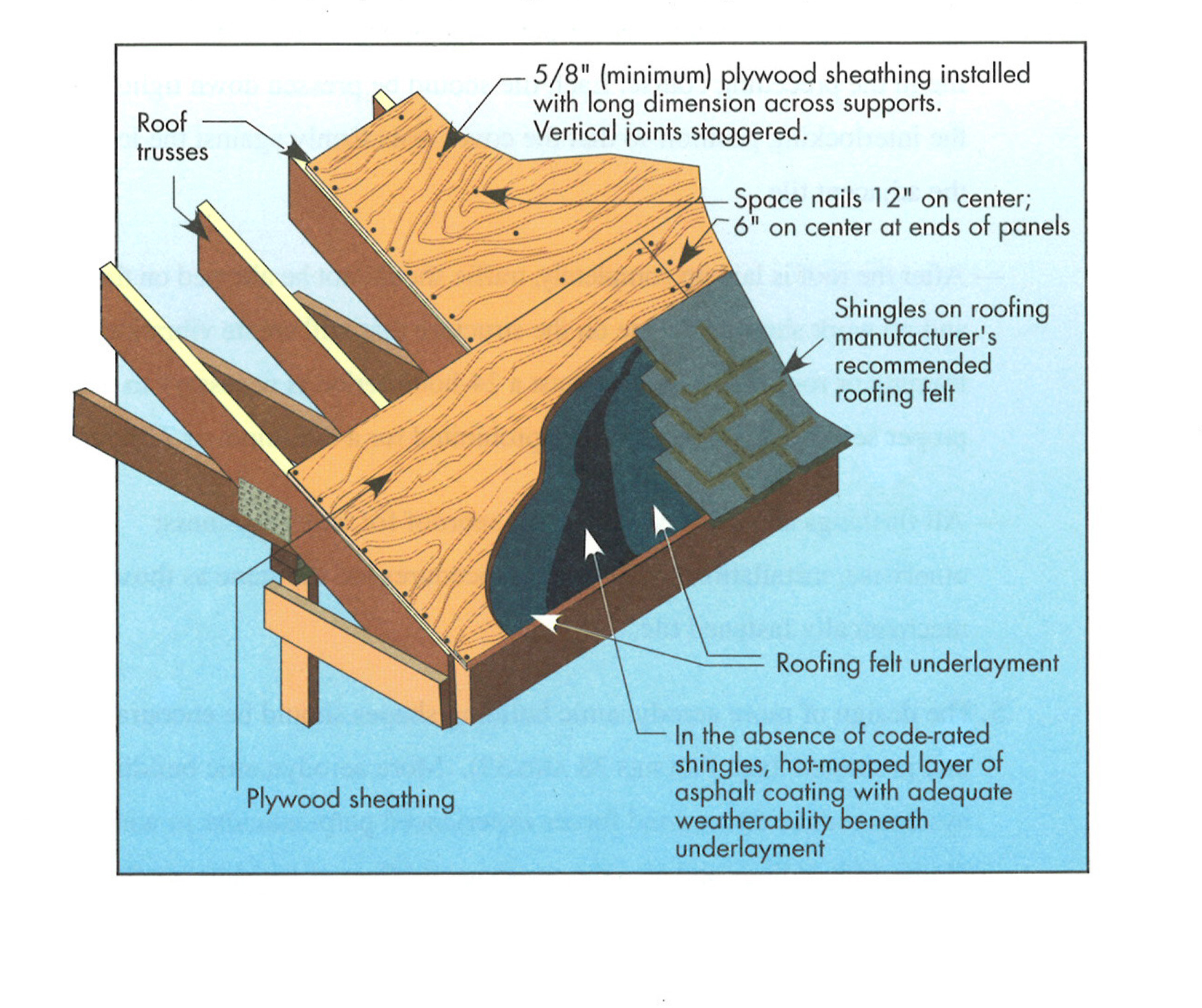
Composition shingle roofing system showing sheathing and hot-mopped underlayment
Image
Image
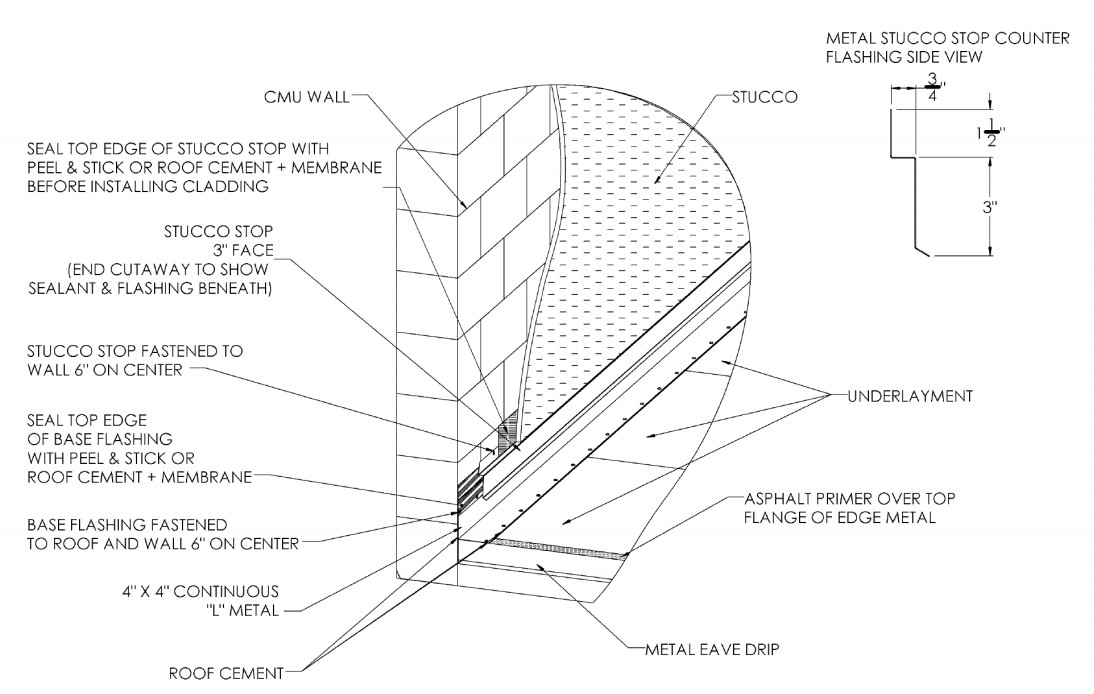
Continuous L-metal flashing integrated with underlayment at roof-wall intersections
Image
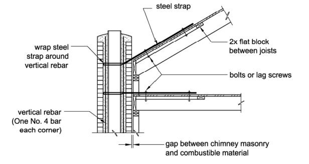
Cross section showing points of reinforcement and attachment to secure the chimney to the roof and ceiling joists.
Image
Image
Image
Detail of an unvented cathedralized attic showing air-impermeable spray foam insulation plus batt insulation installed on the underside of the roof deck.
Image
Image
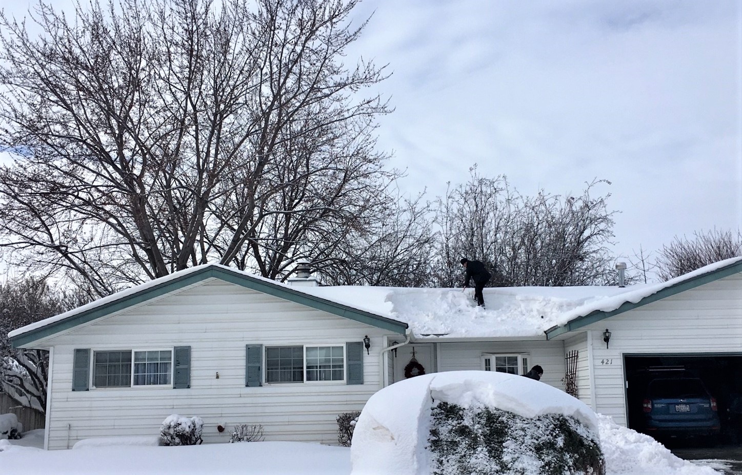
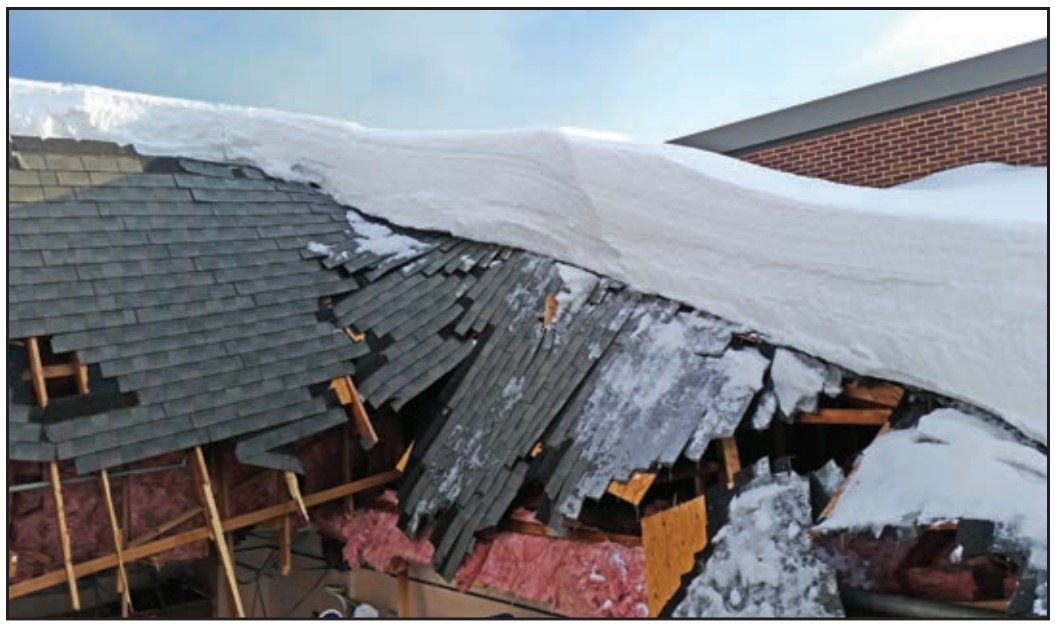
Drifting of snow led to heavy accumulation between the gables which required snow removal to reduce risk of roof collapse
Image
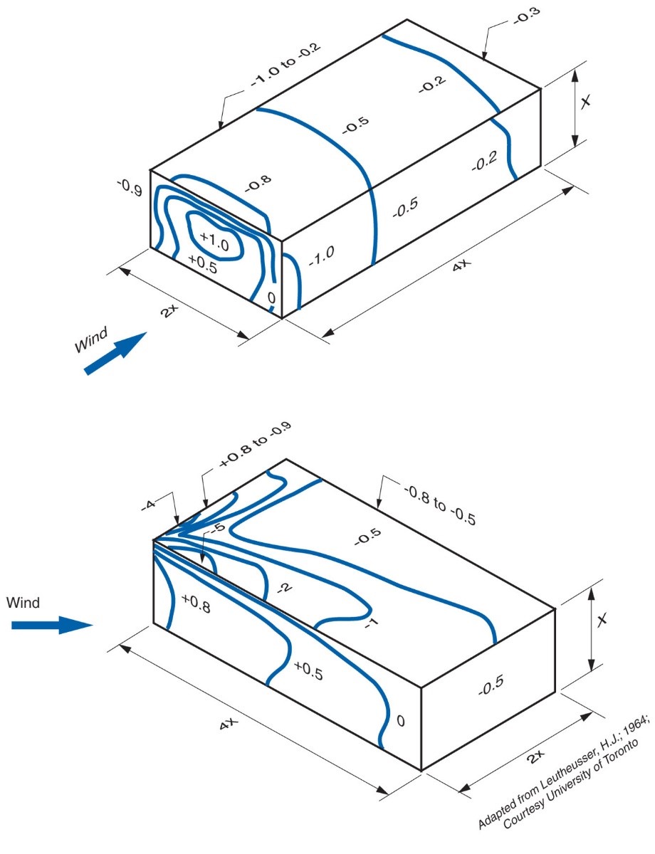
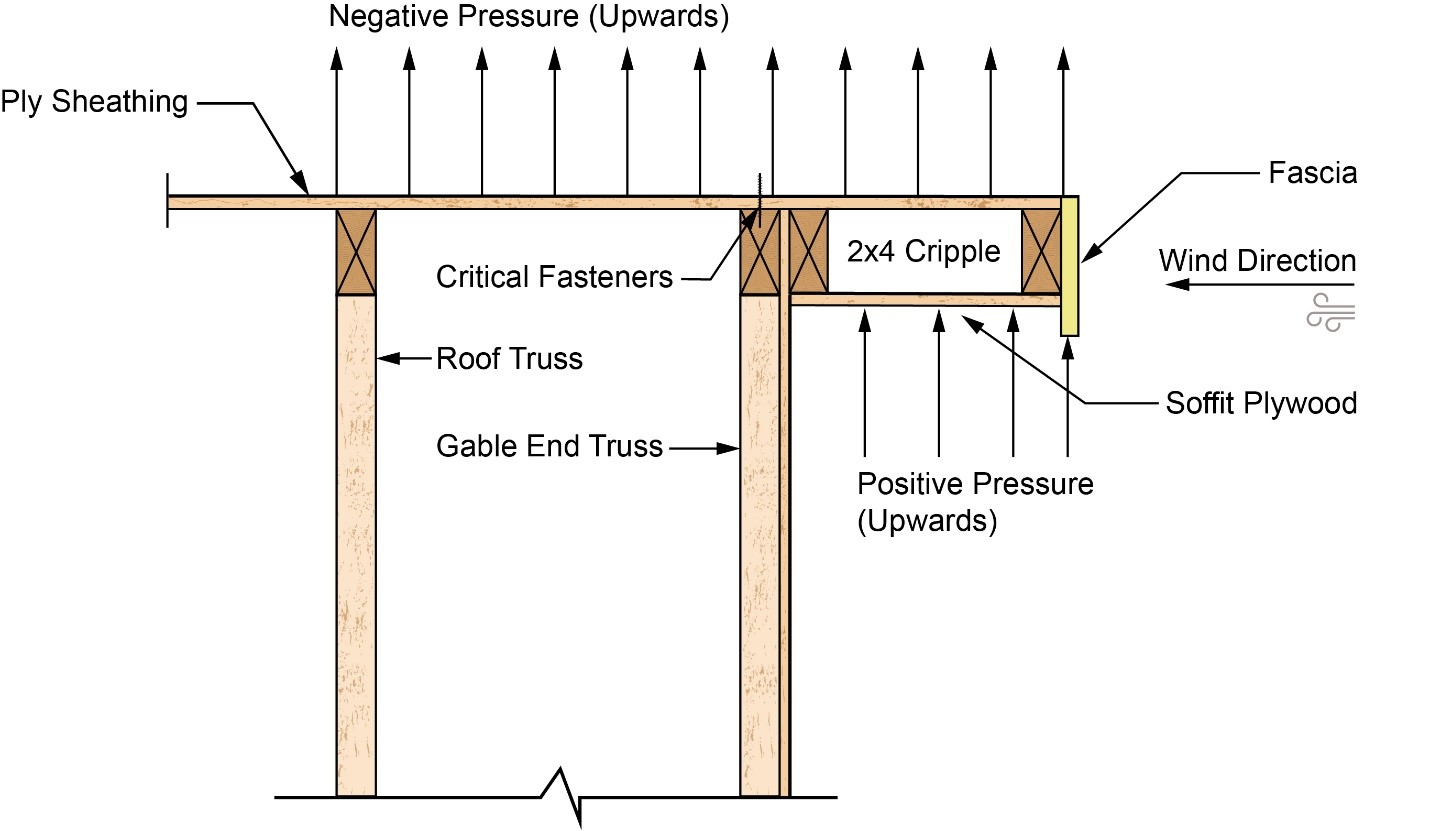
During high wind events, high localized areas of negative pressure (“suction”) occur above roof membranes
Image
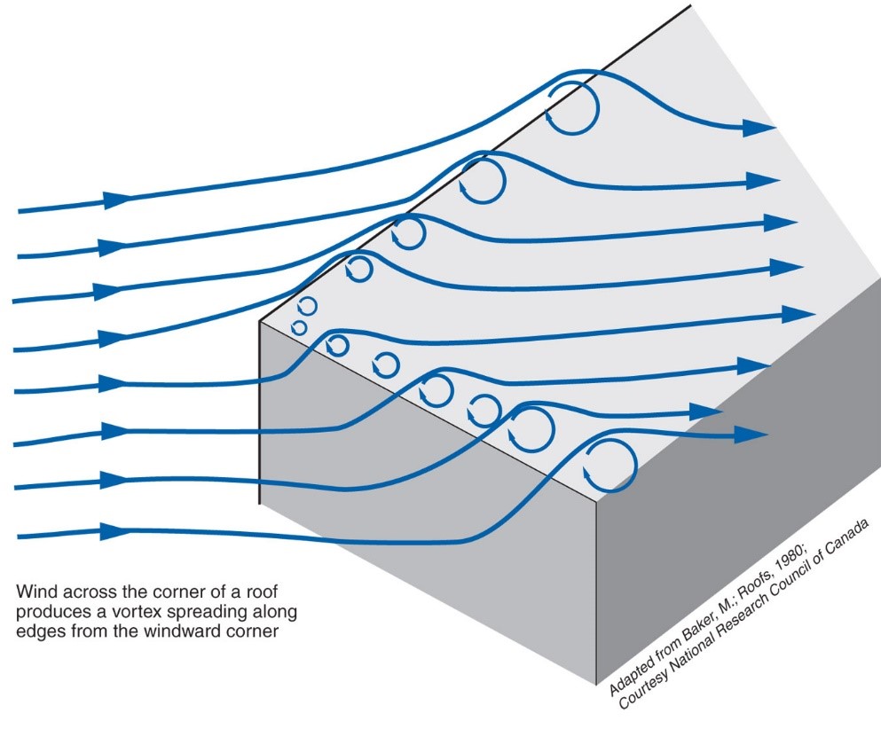
During high wind events, vortices form along the edges of the roof creating areas of localized negative pressure (“suction”) above the roof
Image
End wall failure under hurricane force winds due to inadequate bracing of the gable end wall.
Image
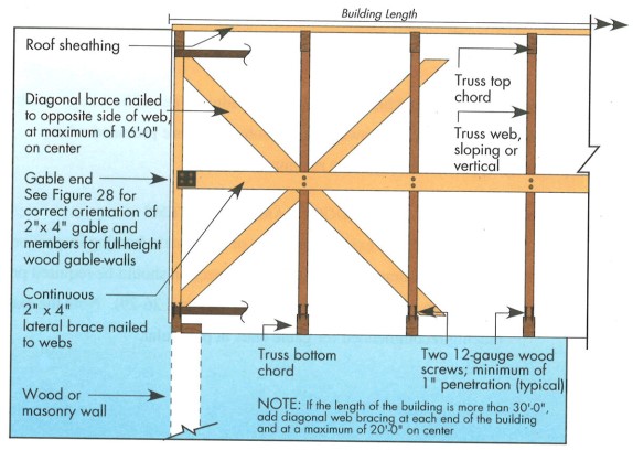
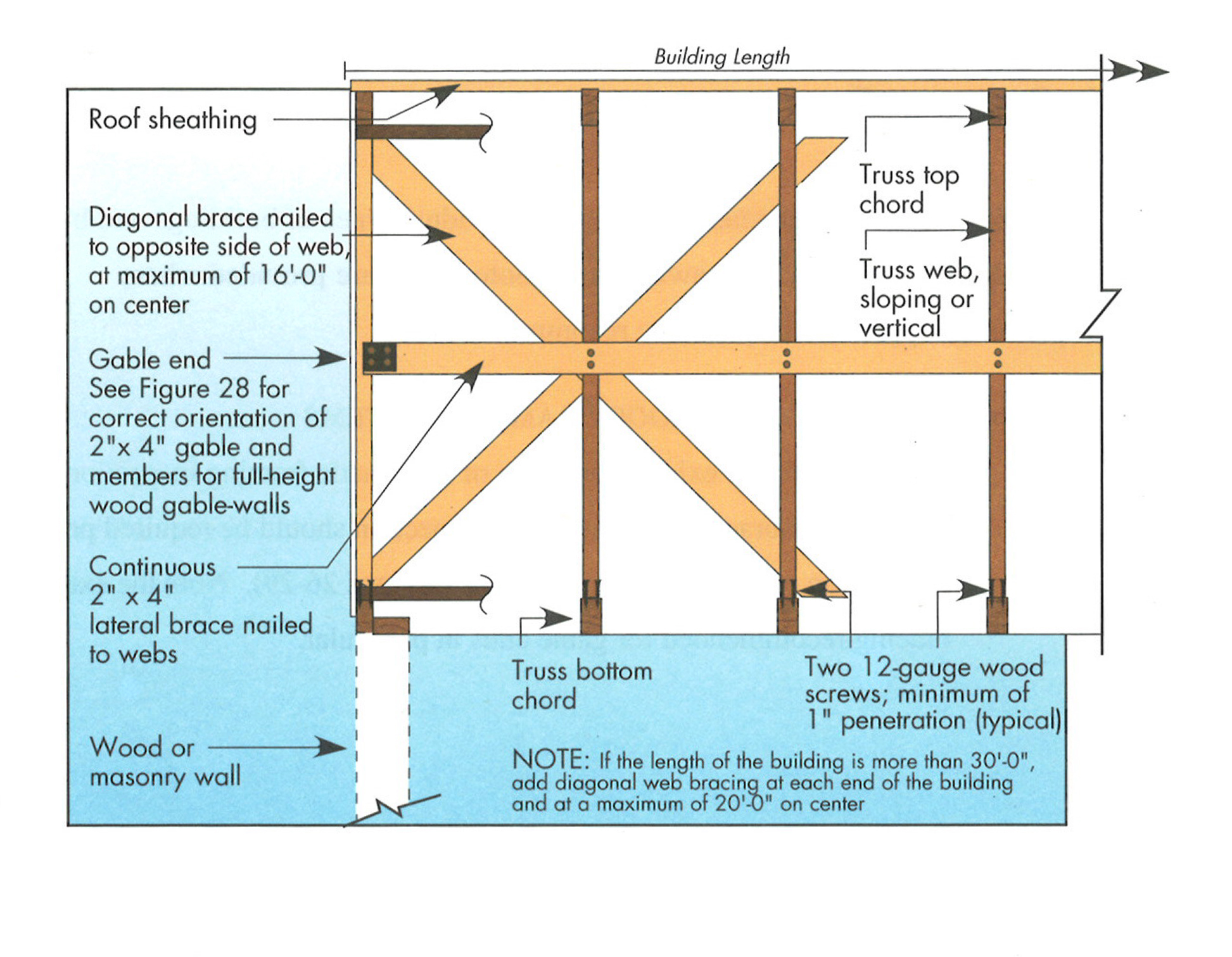
Example A of a gable truss and gable end wall bracing for a home in a hurricane region
Image

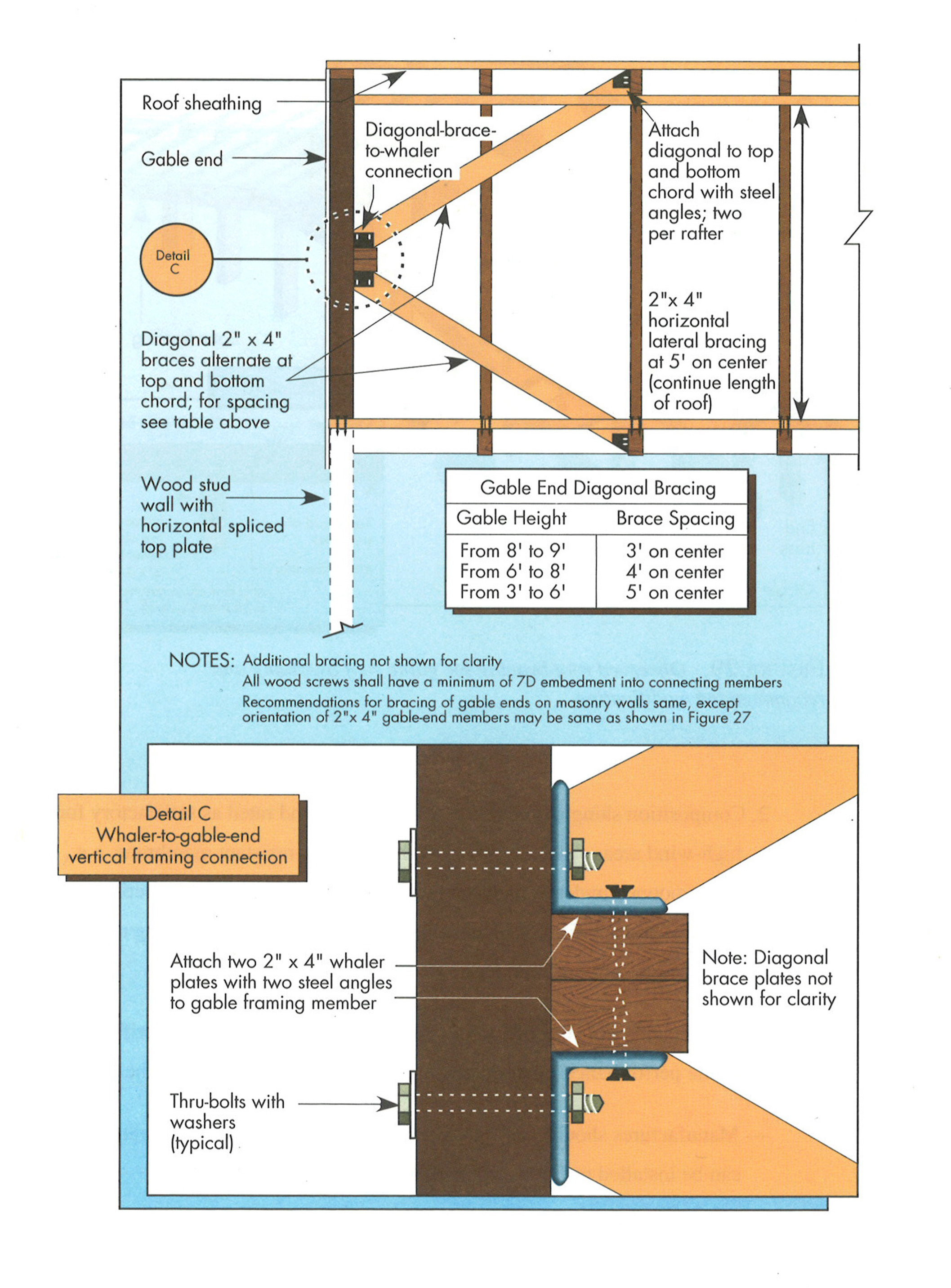
Example B of a gable truss and gable end wall bracing for a home in a hurricane region
Image
Image
Image
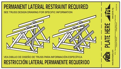
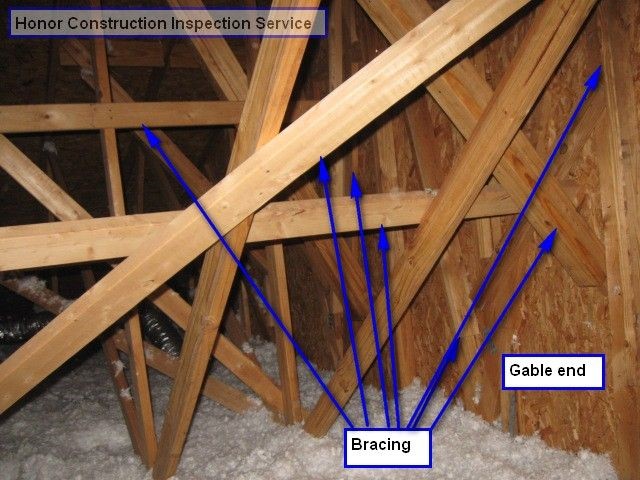
Example of a truss bracing requirement tag that some truss manufactures place strategically onto the truss to remind installers
Image
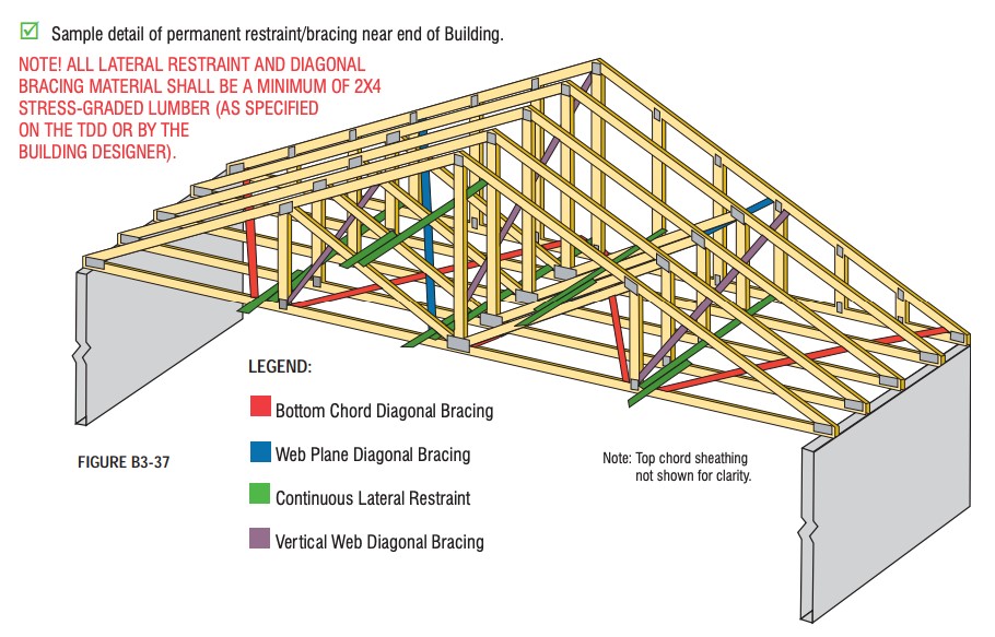
Example truss bracing for resisting wind loads as determined by design software used by truss manufactures
Image
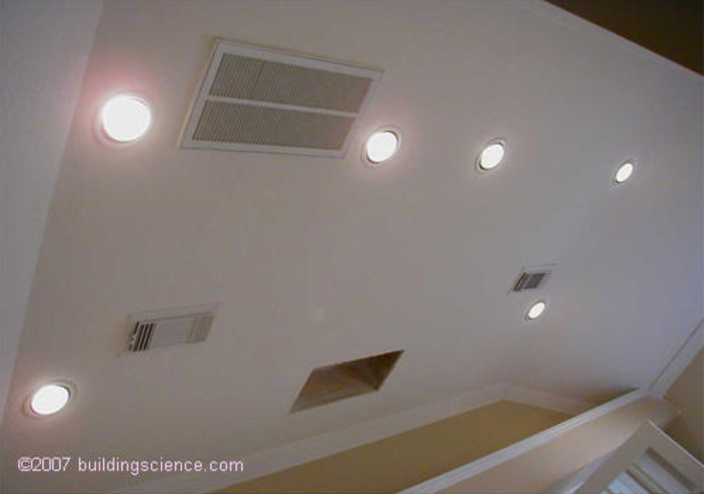
Examples of many common ceiling penetrations that will be difficult to insulate and air seal in this cathedral ceiling.
Image
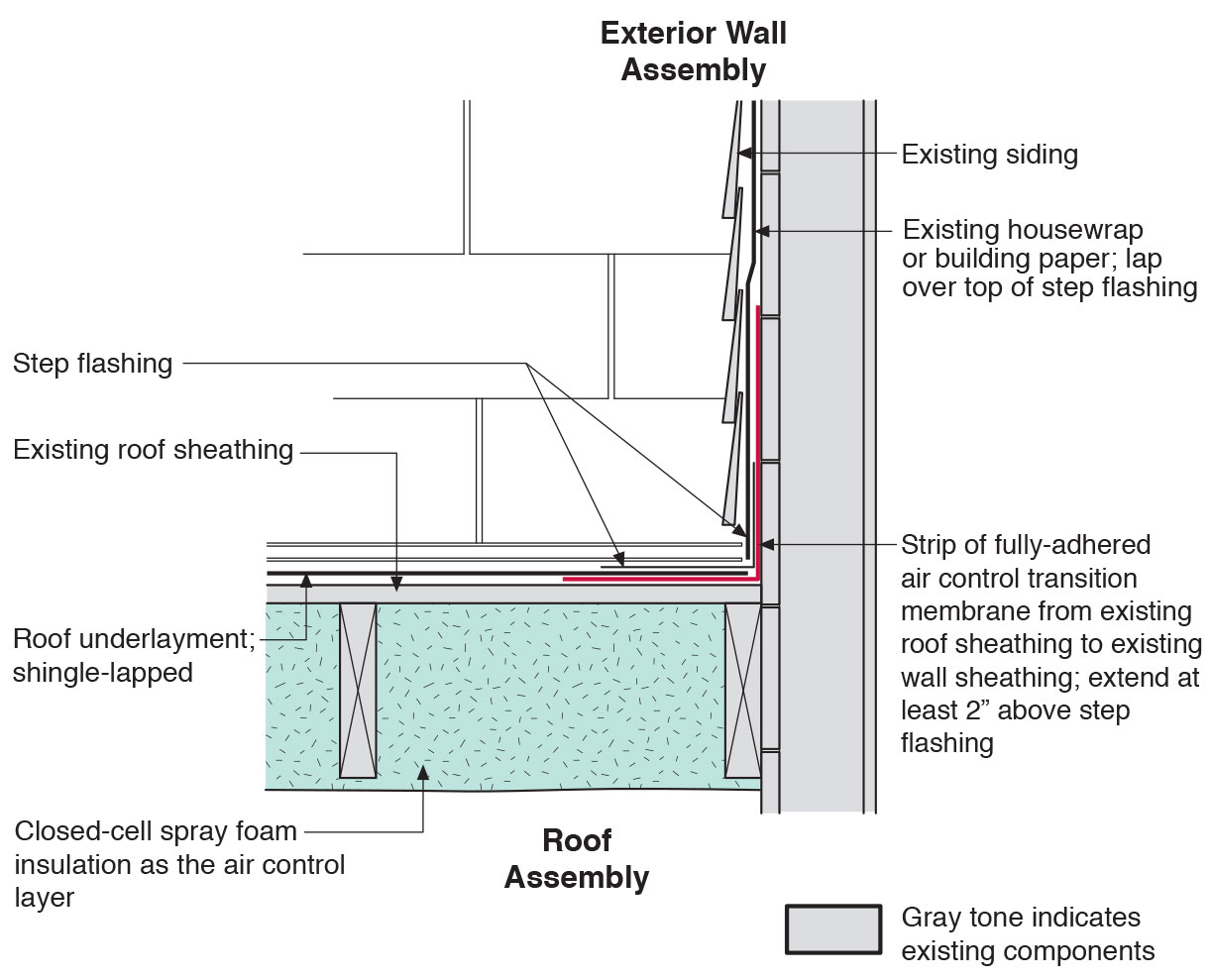
Existing wall-to-lower roof transition retrofitted with a new strip of fully adhered air control transition membrane, new step flashing, new roof underlayment, and new cladding
Image
Existing wall-to-lower roof transition with a new strip of fully adhered air control transition membrane, new step flashing, new roof underlayment, and new cladding – view from eave
Image
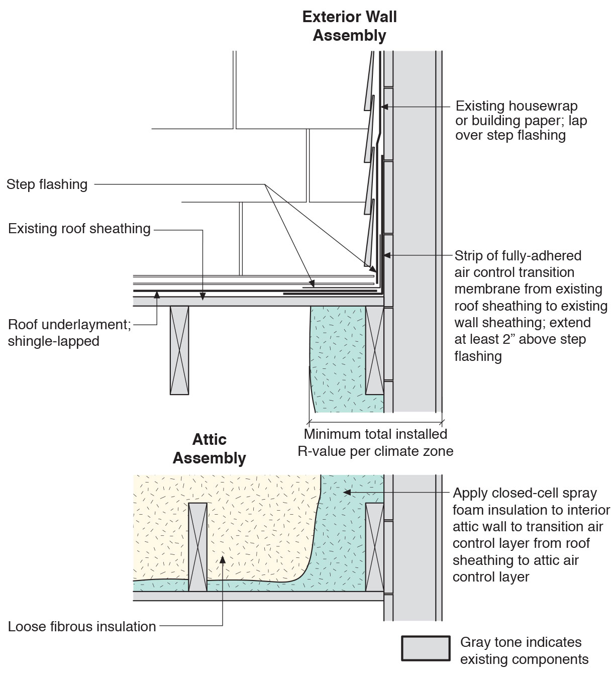
Existing wall-to-lower roof with attic transition with a new strip of fully adhered air control transition membrane, new step flashing, new roof underlayment, and new cladding – view from eave
Image
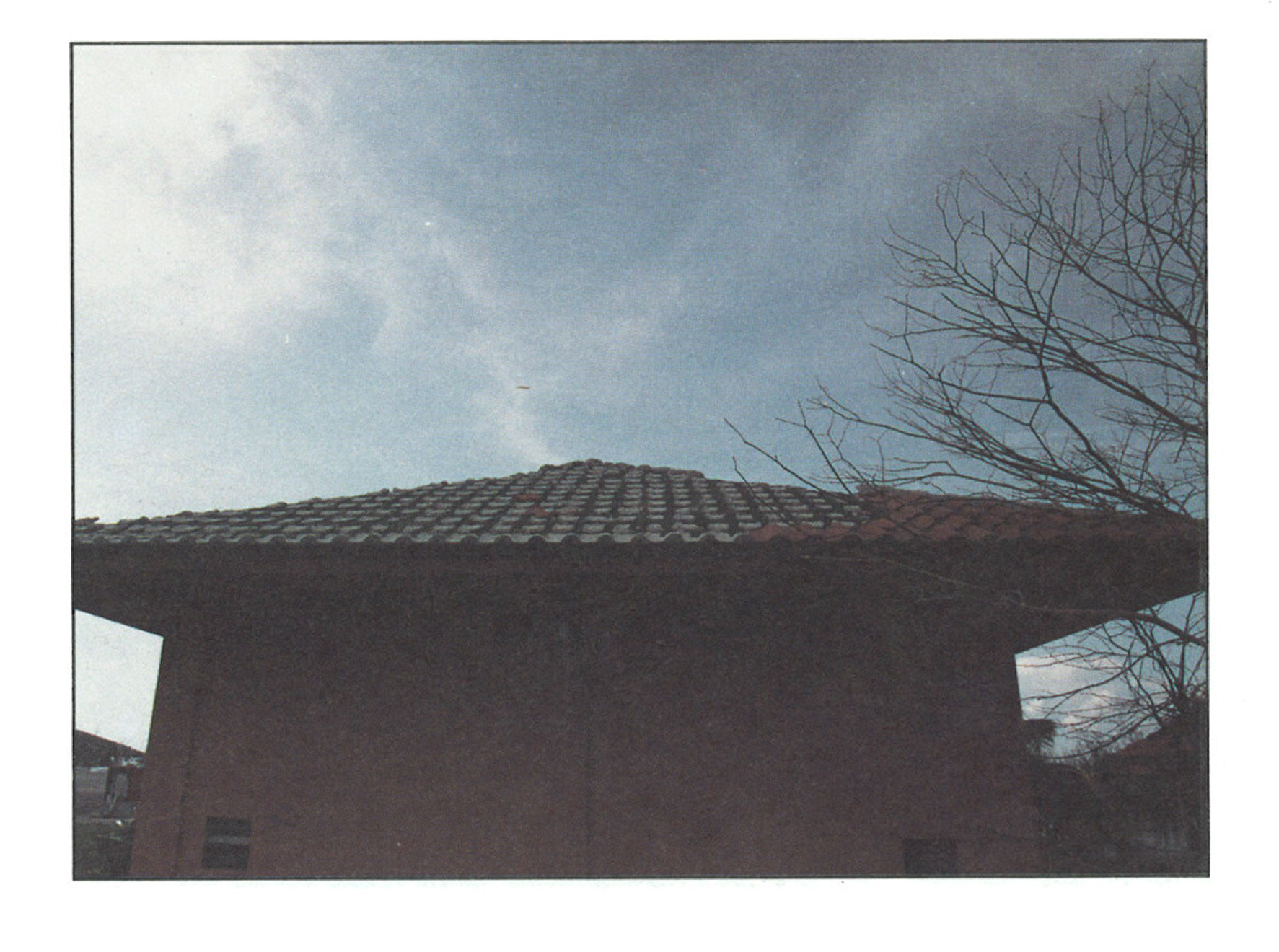
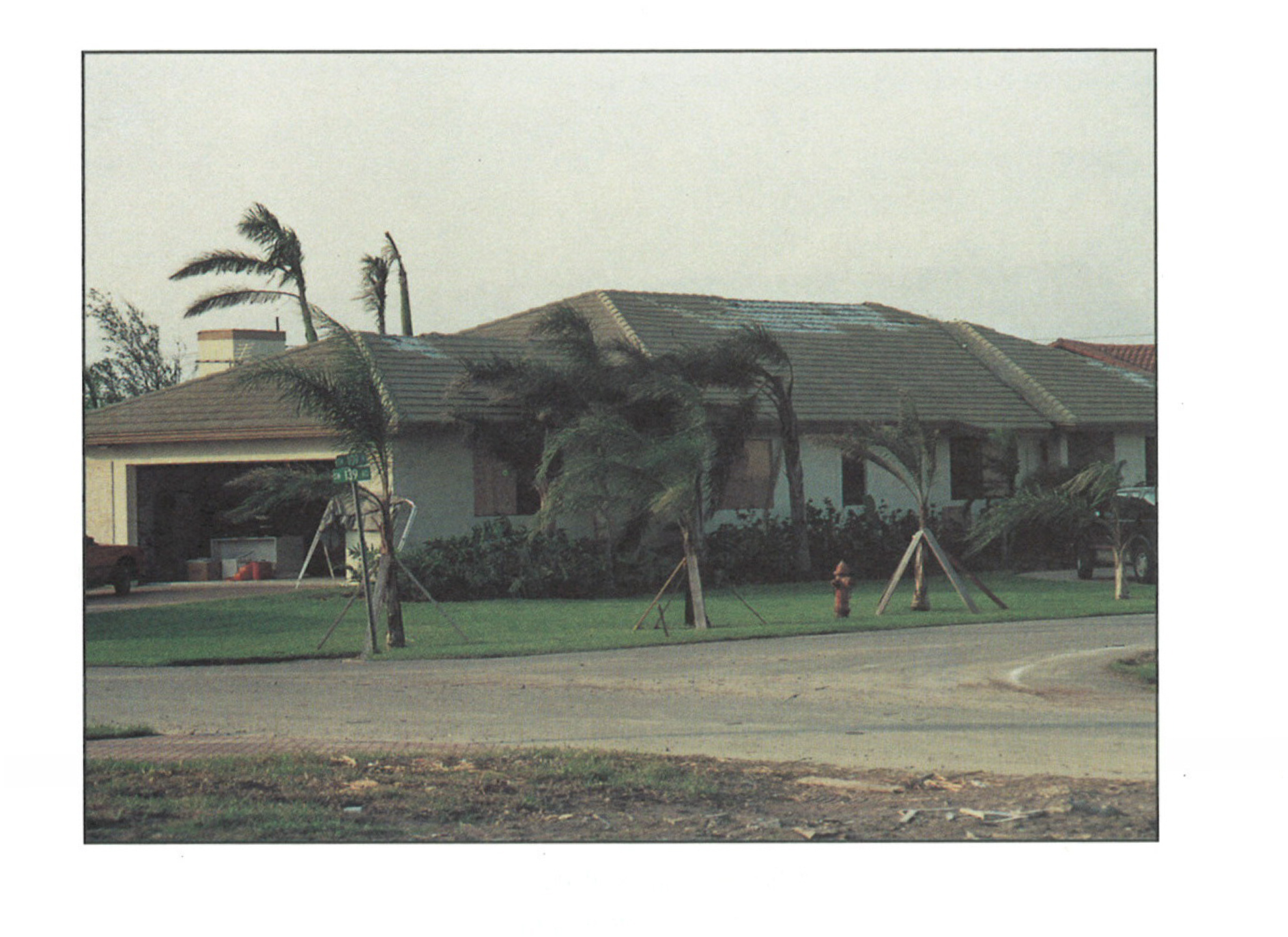
Failure of "S" tile roofing in high winds due to bond failure between mortar and tiles.
Image
Failure of barrel tile roofing due to bond failure between underlayment, mortar, and tiles during a hurricane.
Image
Image
Failure of extruded concrete flat tile roofing due to bond failure between tile, mortar, and underlayment resulting from hurricane force winds.
Image
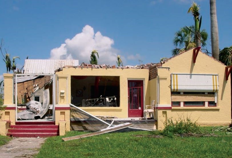
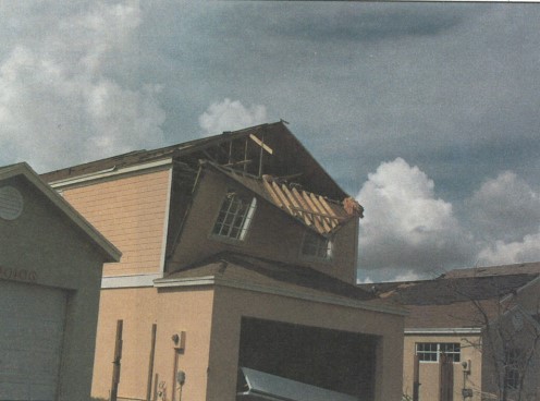
Failure of Roof Structure from Pressurization Due to Window Failure During a Hurricane.
Image
Image
Image
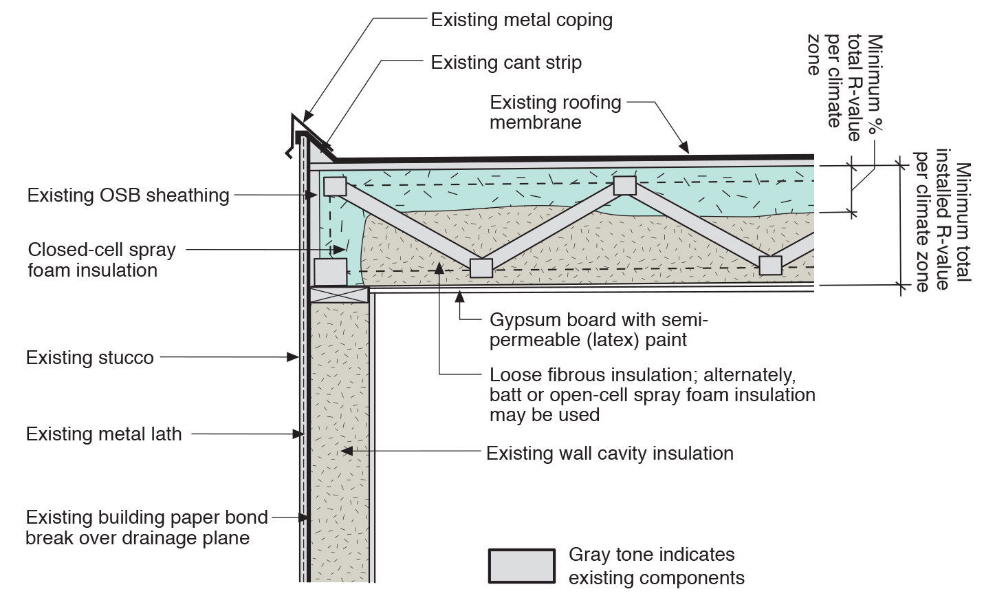
Flat roof with cavity spray foam plus loose-fill insulation and gypsum board thermal barrier.
Image
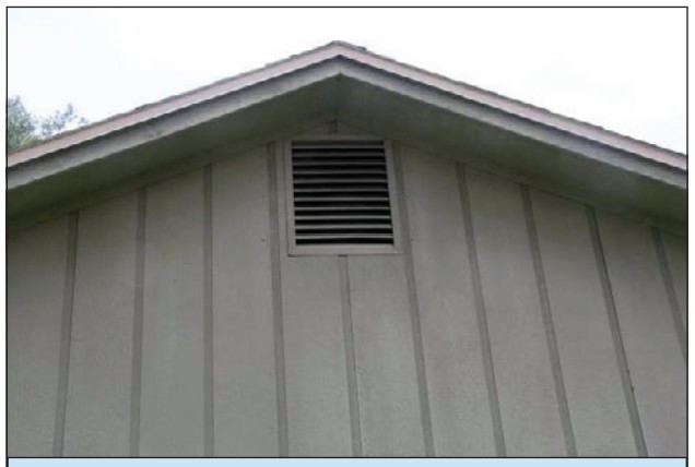
Gable end vents allow in wind-driven rain because pressures that develop between the outside surface of the wall and the inside of the attic are sufficient to drive water uphill several inches.
Image
Image
Image
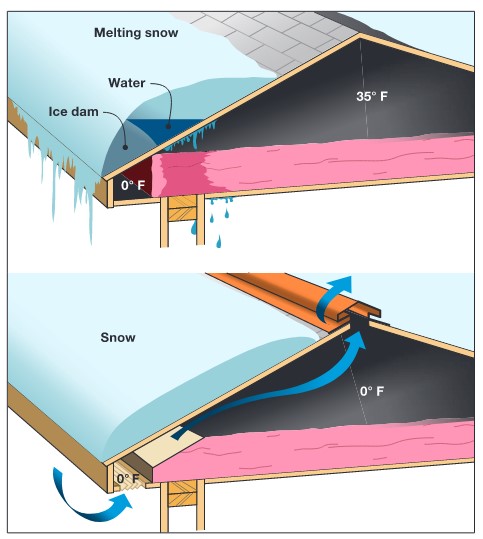
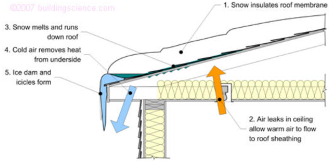
Heat loss through the roof of a home in a cold climate zone leads to snow melting to form ice dams.
Image
Image

Image
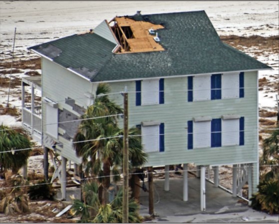
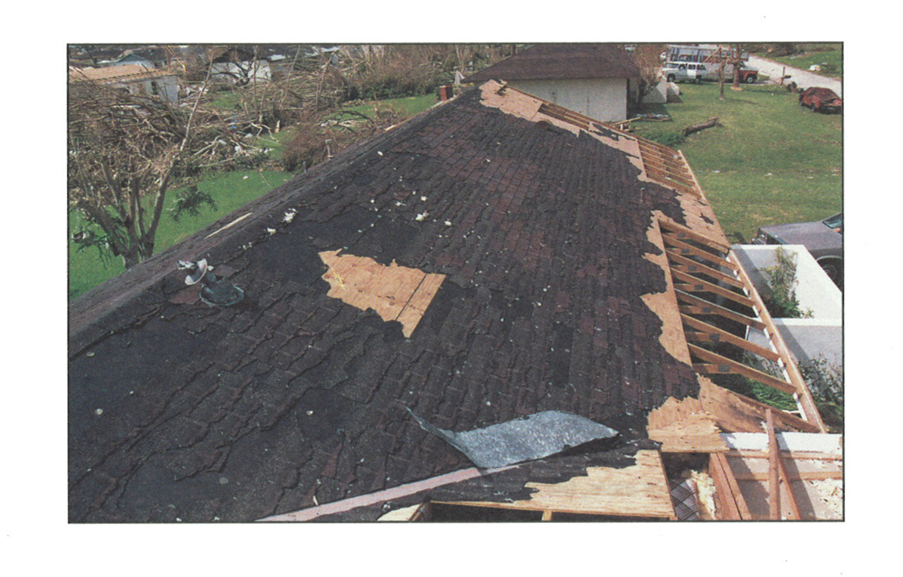
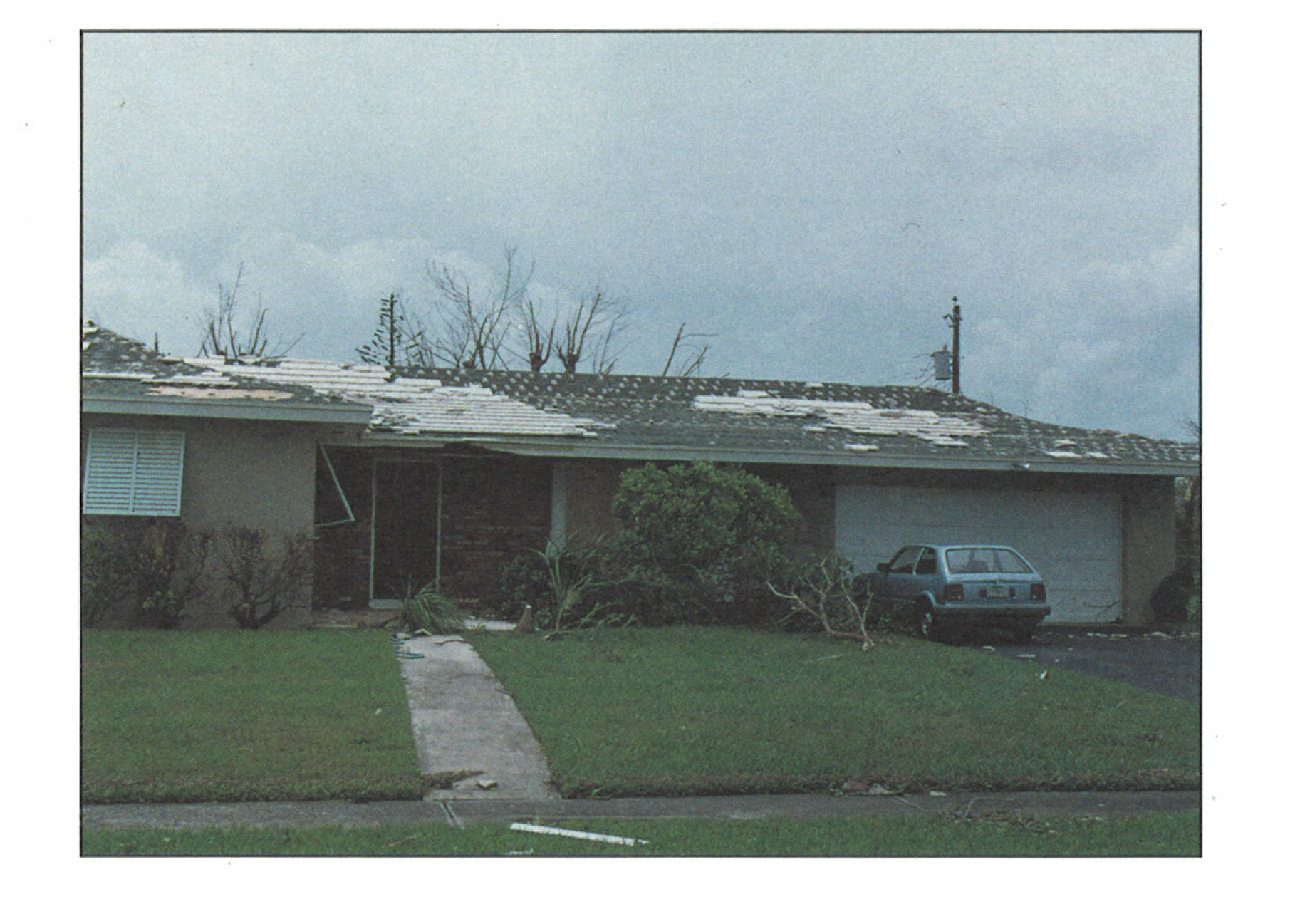
High winds pulled the asphalt shingles and sheathing panels off this coastal home, although storm shutters protected the windows
Image
Image
Image
Image
Image
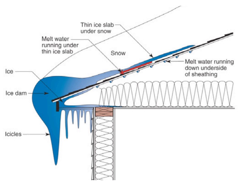
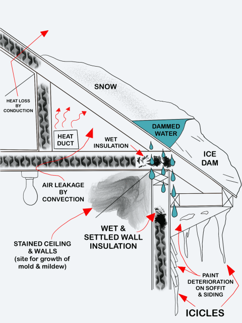
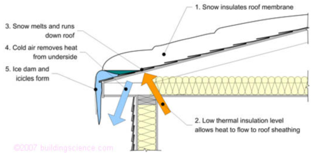
Ice dams form when warmth from the attic causes roof snow to melt and flow to roof eaves where it refreezes at the colder overhang and forms a buildup of ice causing more snowmelt to puddle where it can wick back through shingles and leak into the attic
Image
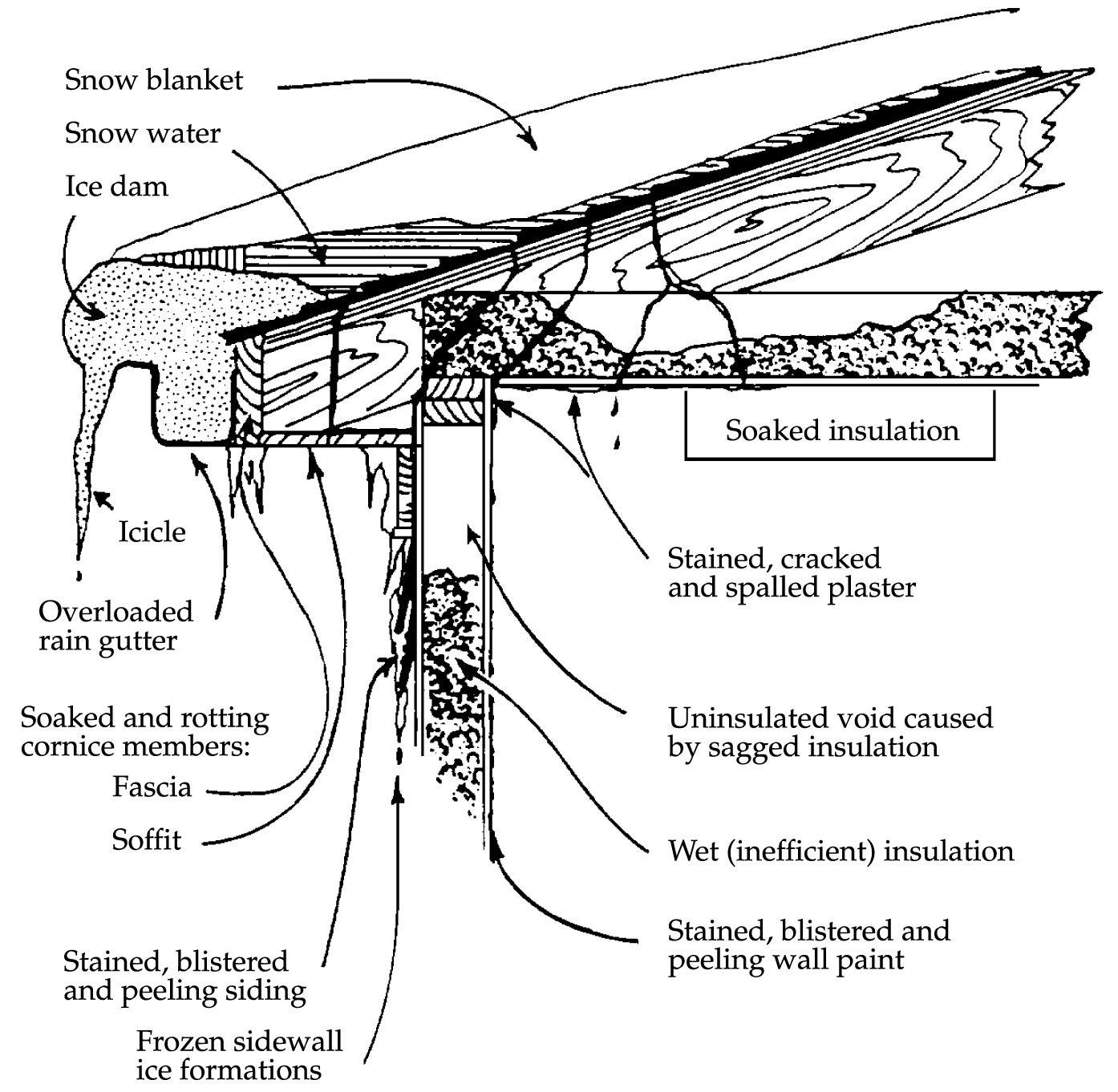
Ice dams formed by melting of snow on roofs can affect roofs, walls, ceilings, siding, and insulation.
Image
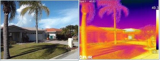
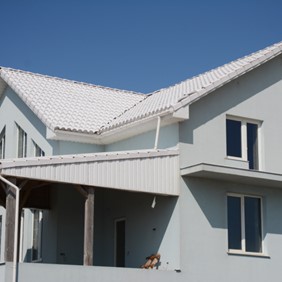
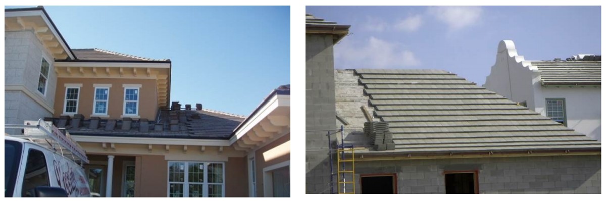
If a cool room is directly under an attic or roof, having lighter colored roofing (home on left) will reduce heat gain to the space as compared to darker roofing (home on right) because the temperature of the roof will be lower (see thermal image)
Image
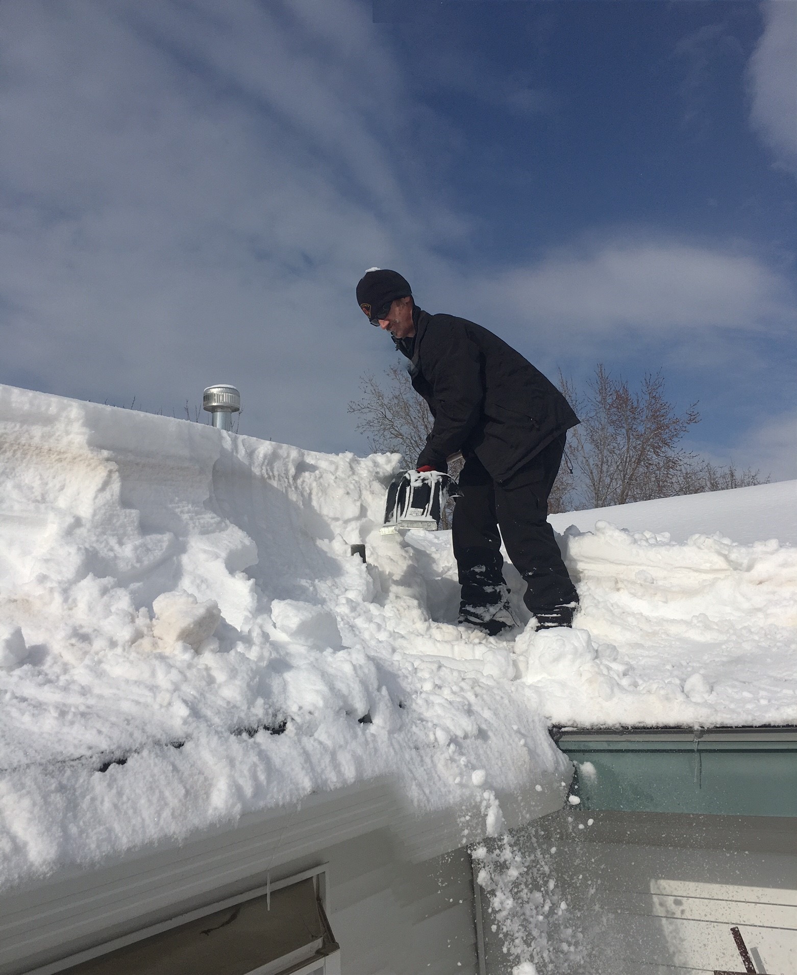
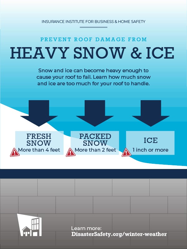
If snow level is estimated to exceed roof load limits, snow removal may be needed; hire professionals
Image
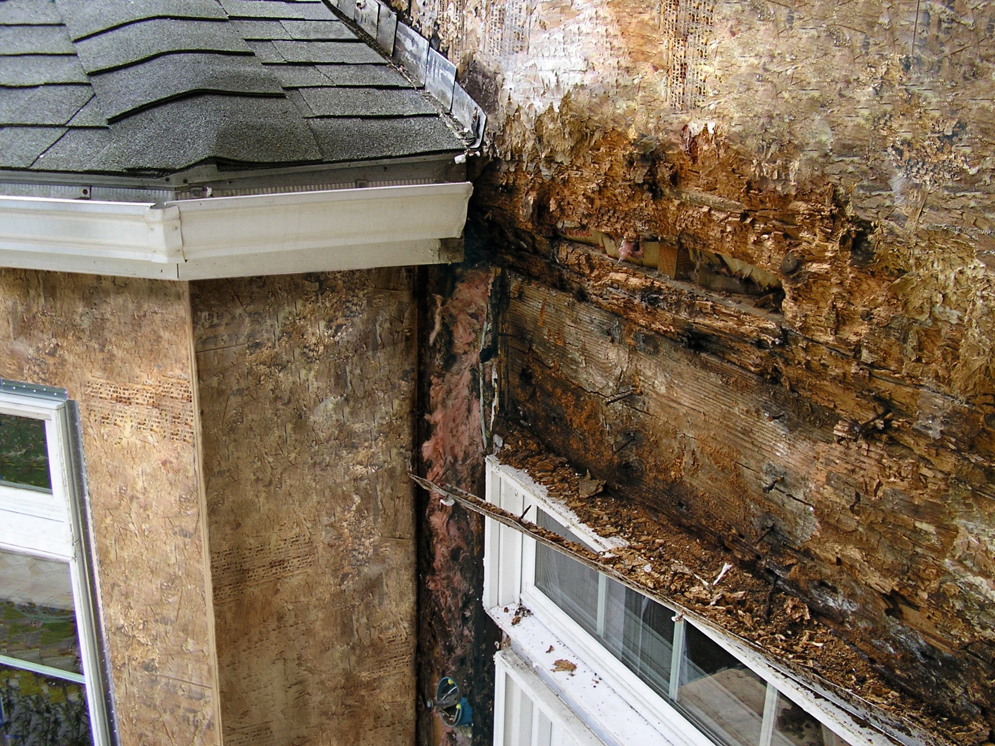
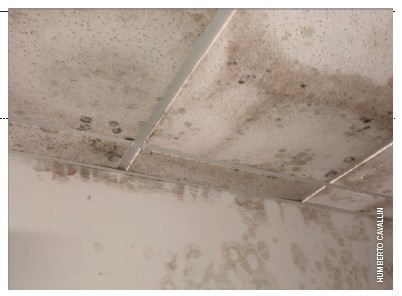
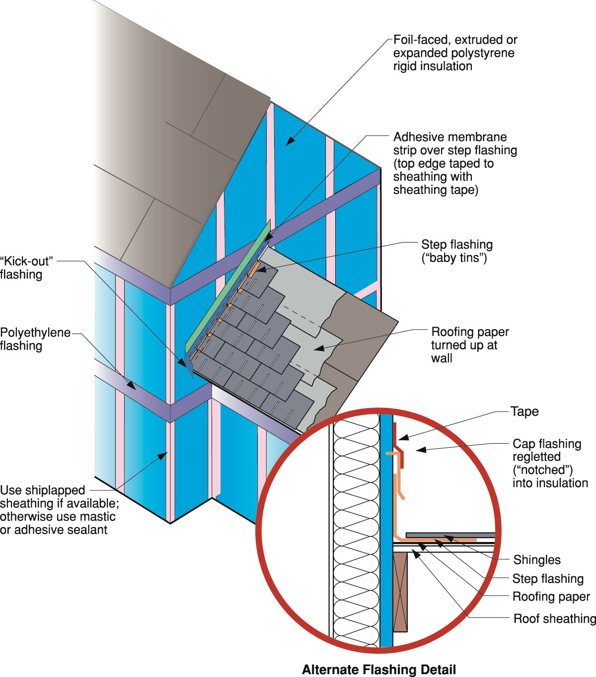
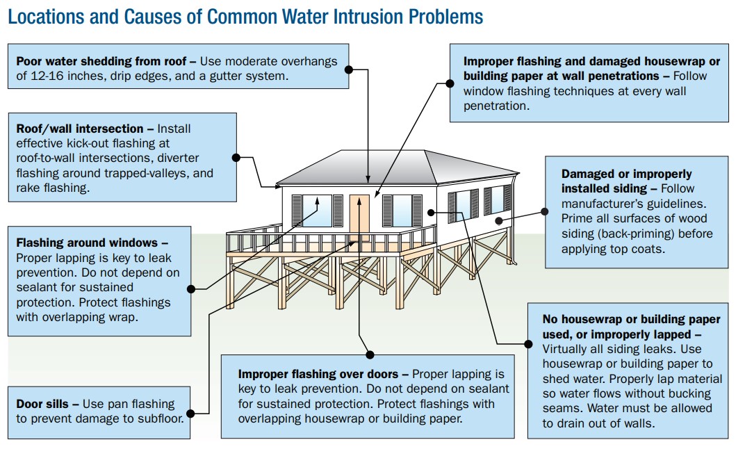
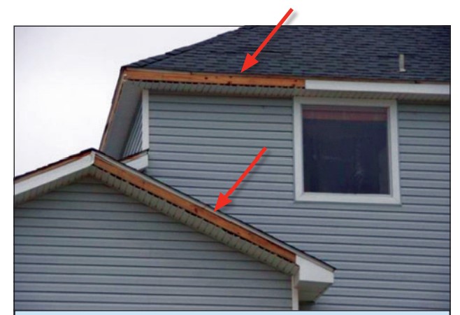
Improper flashing can allow rain water into walls, causing significant damage
Image
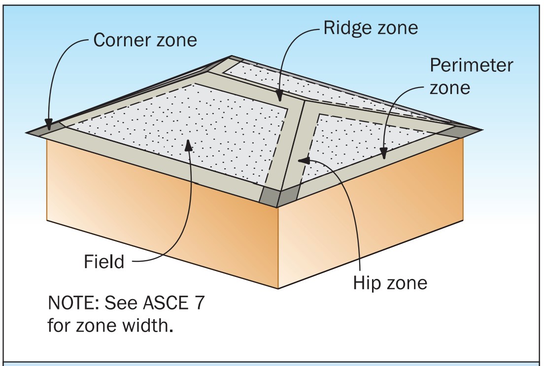
In high wind zones, if roof tiles are fastened with screws or nails, consider using clips on tiles at the corners, ridges, hips, and perimeters.
Image
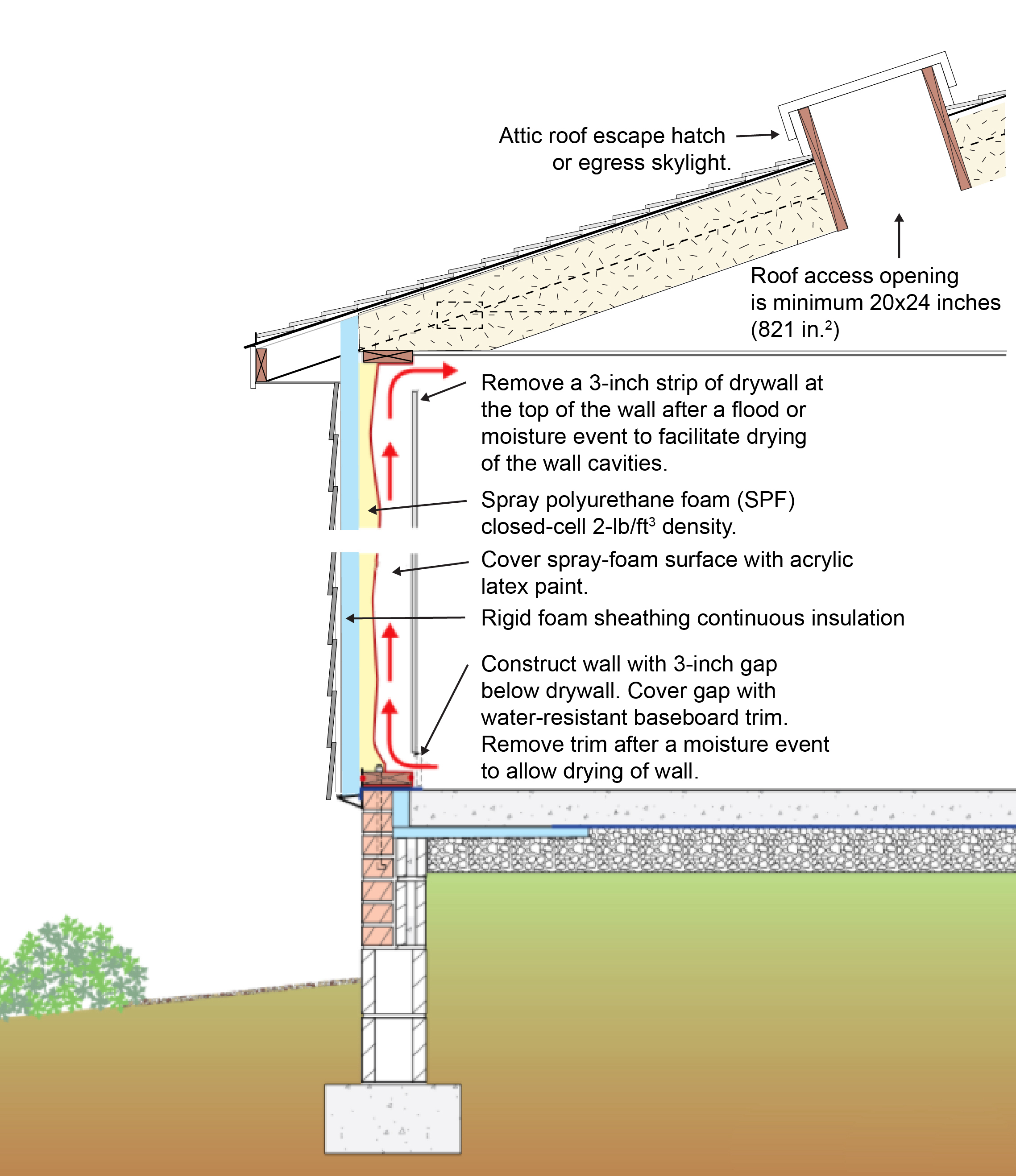
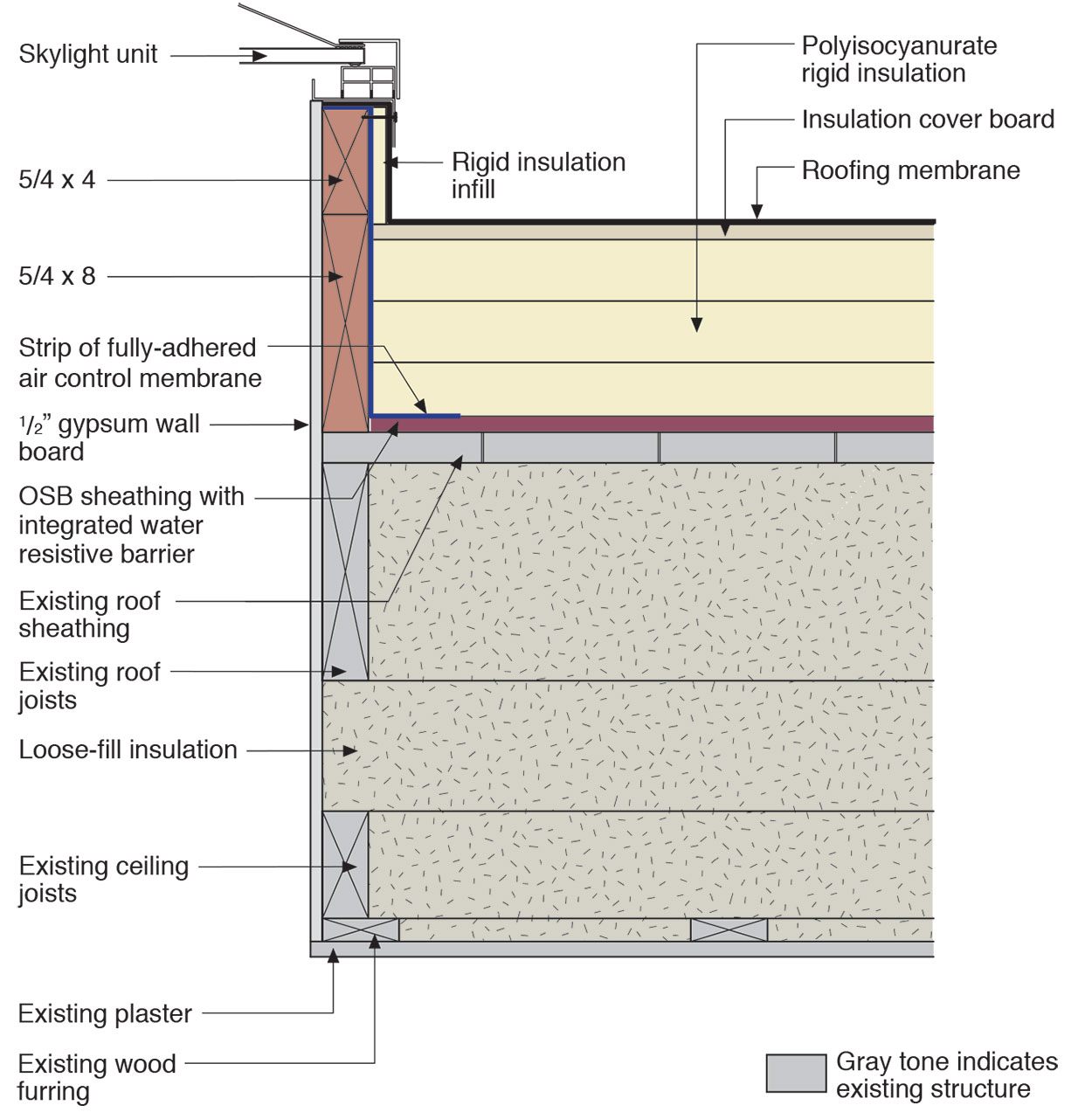
In high-flood-risk areas, install a roof hatch or openable skylight, min. 20x24 inches or 821 in.2 to serve as a means to access the roof for refuge
Image
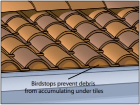
Install birdstop at the eave in tile roofs to minimize the accumulation of debris, a fire hazard, at the roof edge.
Image
Image
Image
Install shingle starter strip then kick-out diverter; attach to roof deck but not sidewall
Image
Install the house wrap. Cut house wrap to fit over diverter and tape top of cut wrap
Image

Image
Image
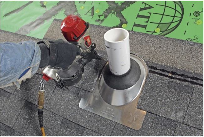
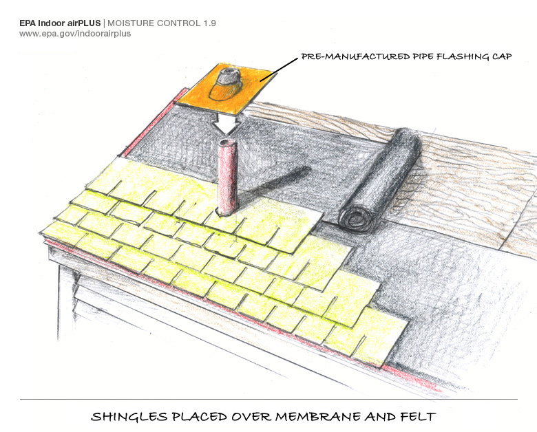
Integrate pre-formed vent pipe flashing, shingle-fashion, with roofing underlayment and shingles
Image
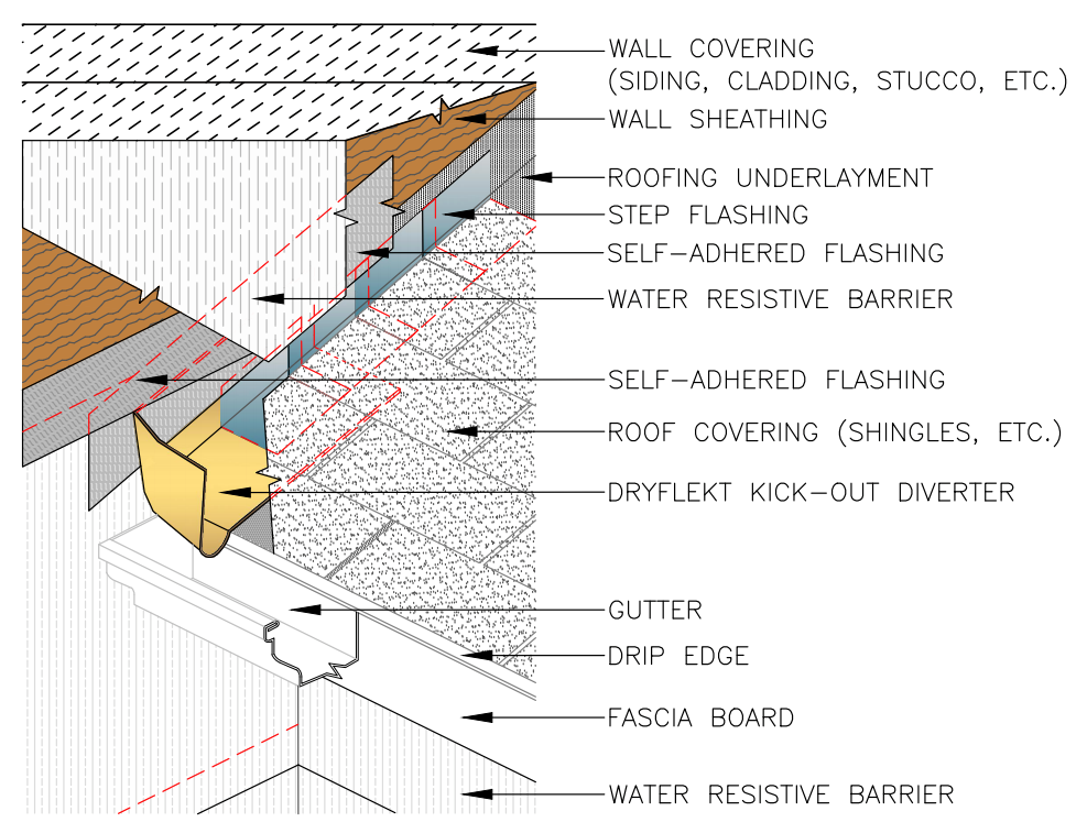
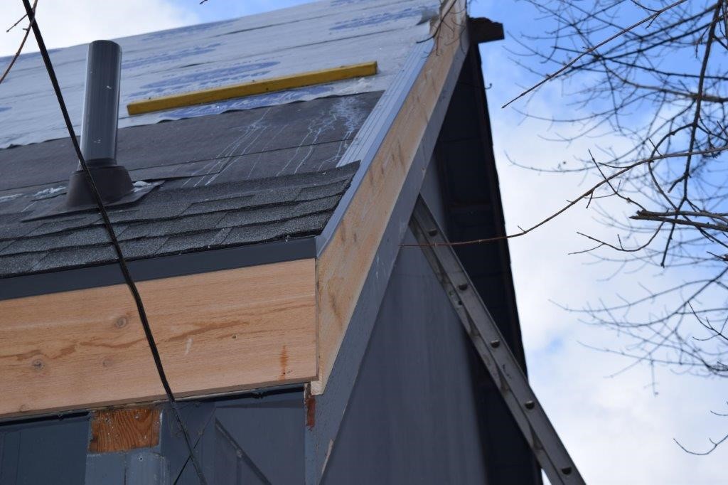
Kickout diverter flashing keeps bulk water from the roof from overflowing the gutter and continuously wetting the siding material.
Image
Lack of insulation over the top plate can lead to ice dam formation on a low sloped roof.
Image
Image
Image
Image
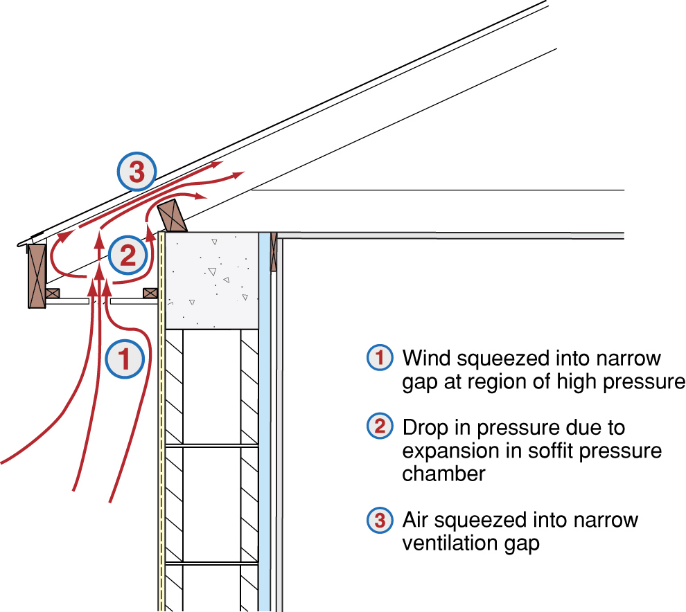
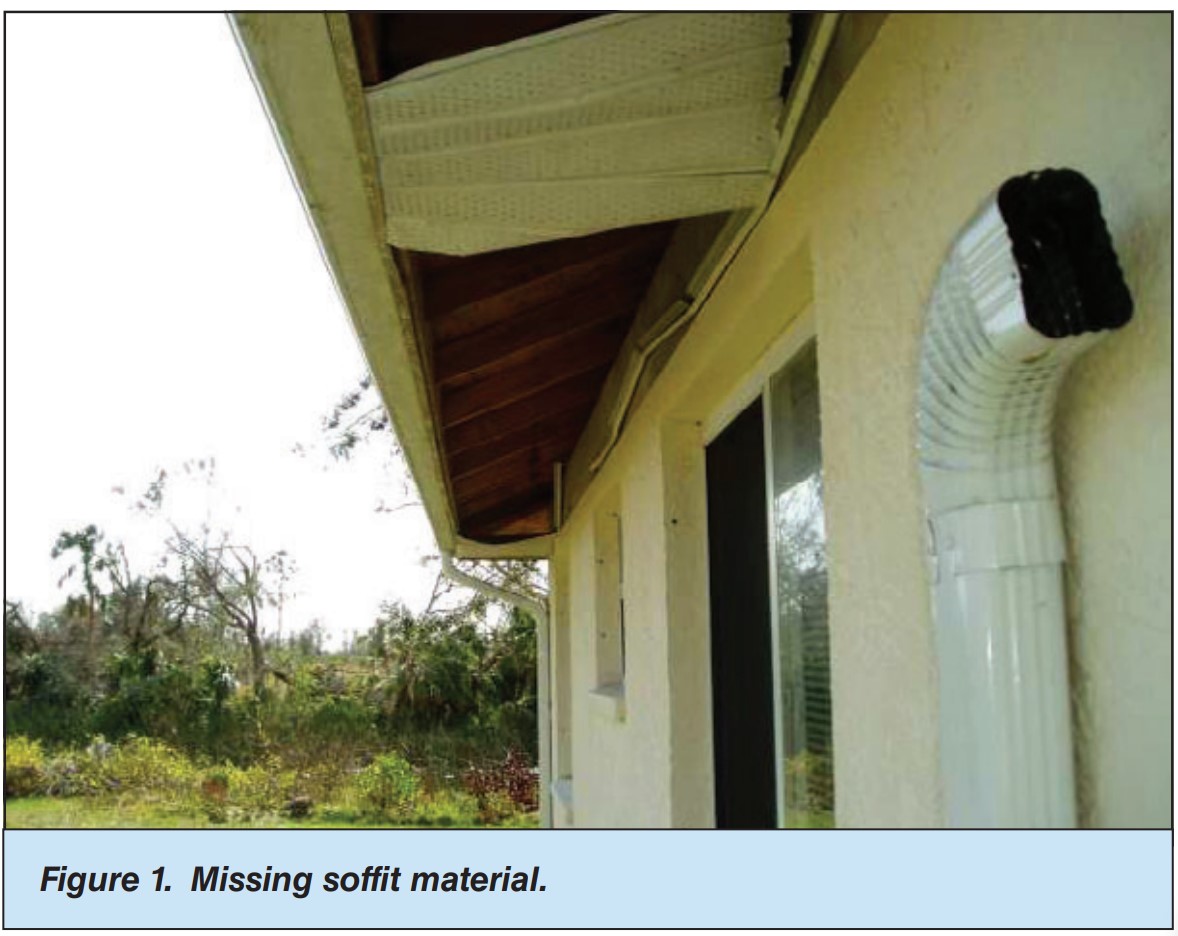
Loss of the fascia cover in high winds exposes the vinyl soffit to entry by wind-driven rain.
Image
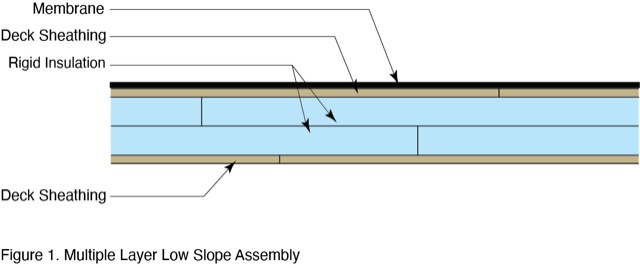
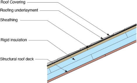
Low-slope roof assemblies constructed of two deck sheathing layers sandwiching rigid foam, and topped with mechanically fastened membrane
Image
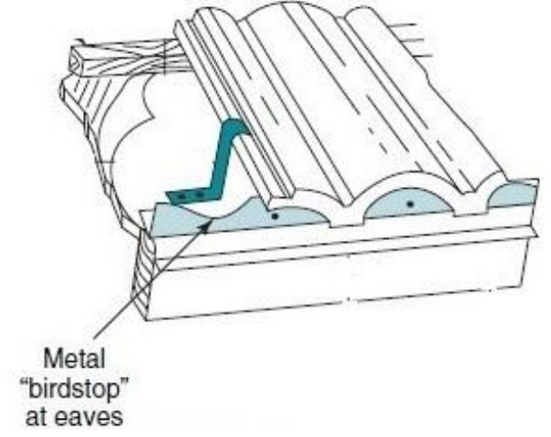
Metal birdstop is installed at the eaves of a tile roof to keep out birds, bats, rodents, and flying insects
Image
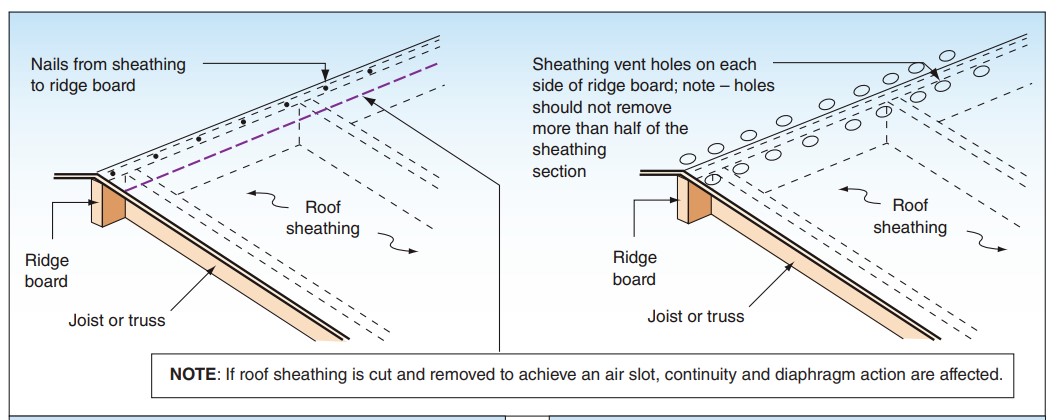
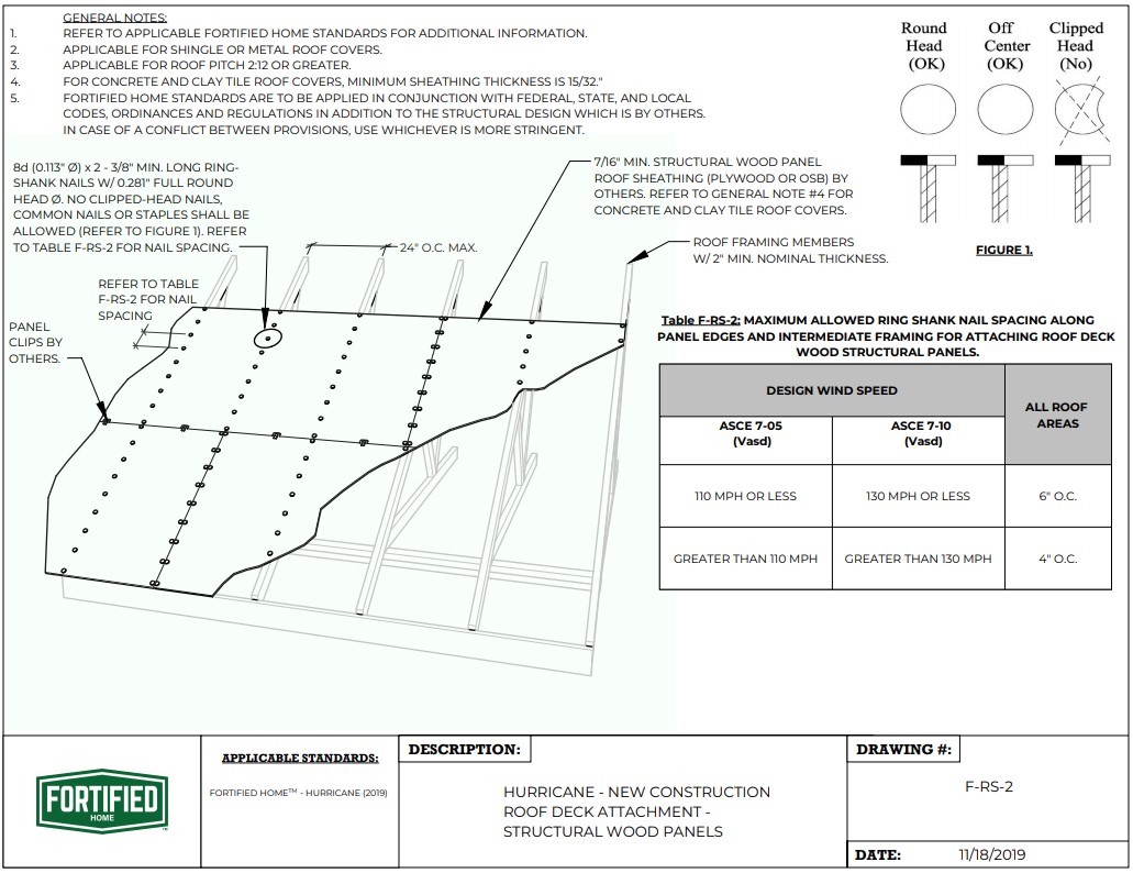
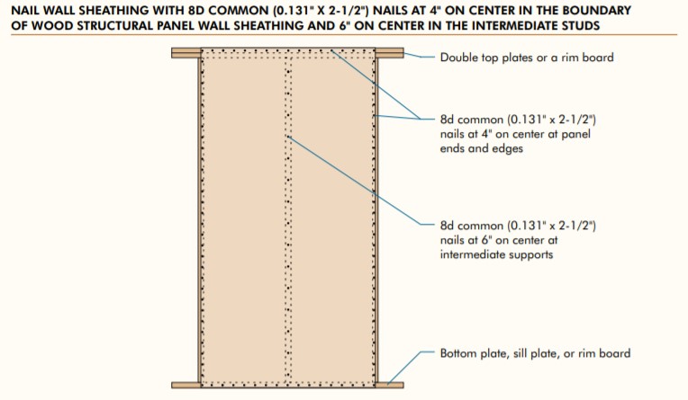
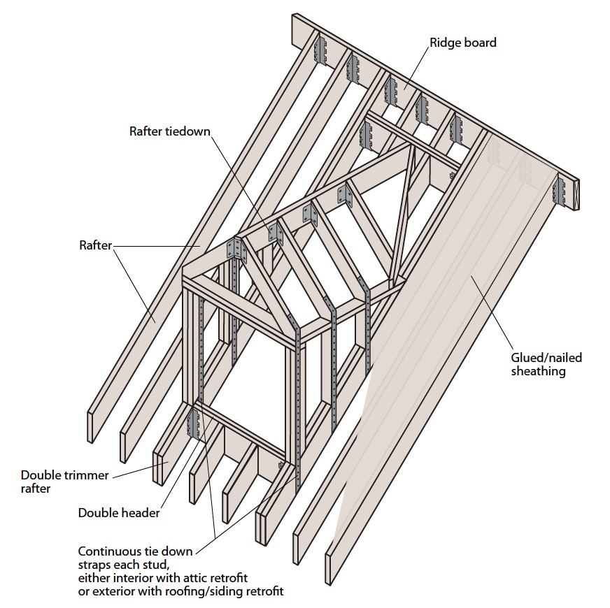
Nailing and ridge ventilation for roof sheathing used as a structural diaphragm in high-wind and seismic hazard areas.
Image
Image
Image
Image
Image
Image
Place first shingle and next section of sidewall flashing over upper edge of diverter
Image

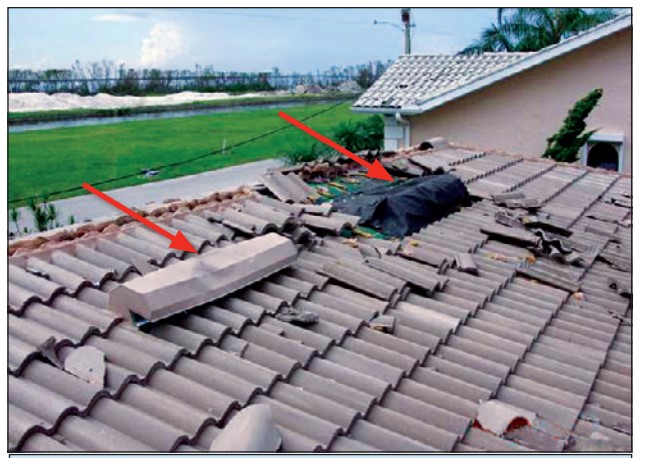
Poor installation can result in the loss of tile roofing in high wind regions, regardless of whether the tiles are attached with mortar, screws, nails, or foam adhesive.
Image
Image
Image
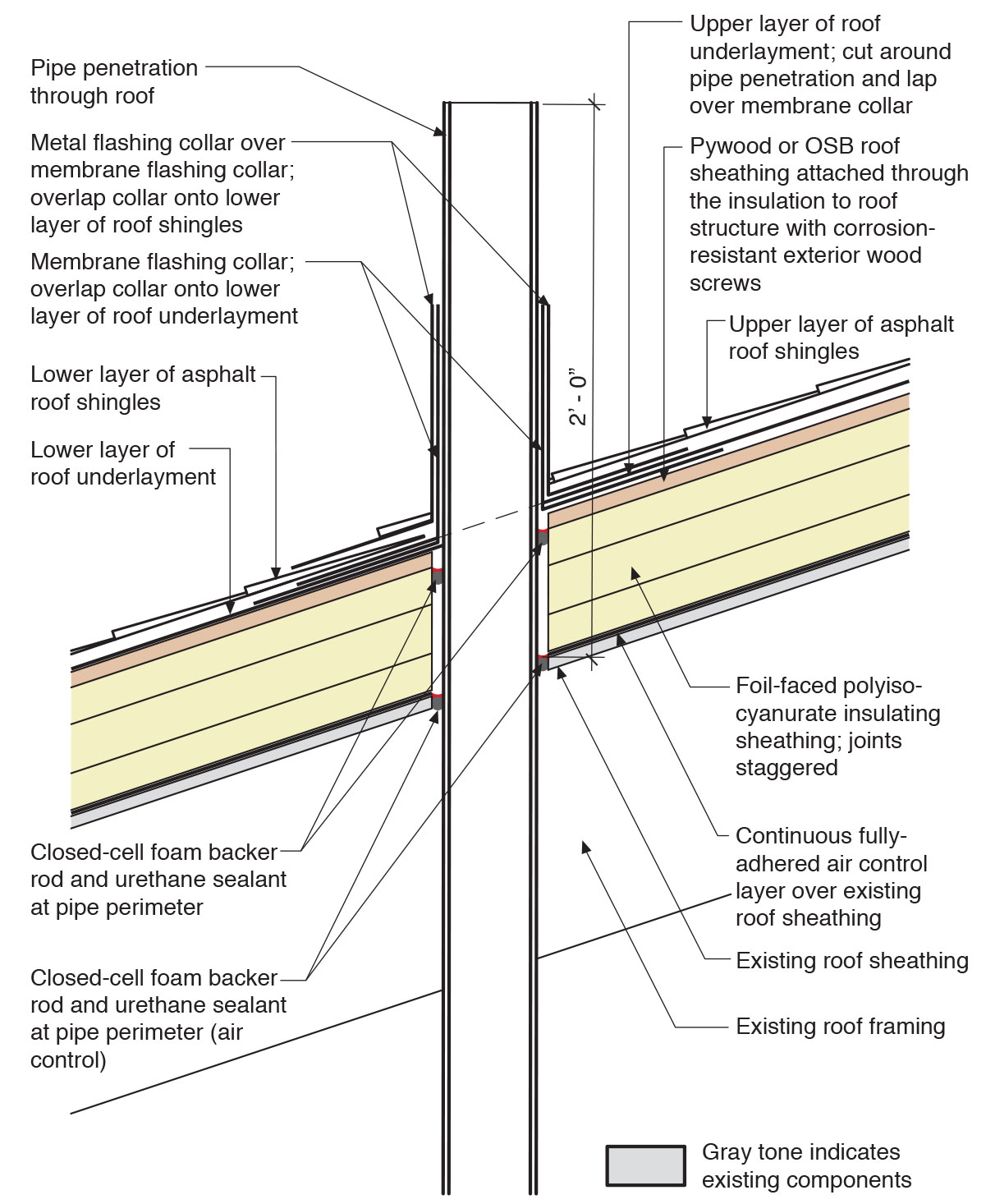
Provide flashing and sealing integrated with the air and water control layers for vents and other roof penetrations
Image
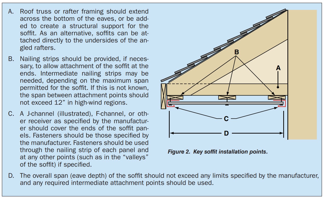
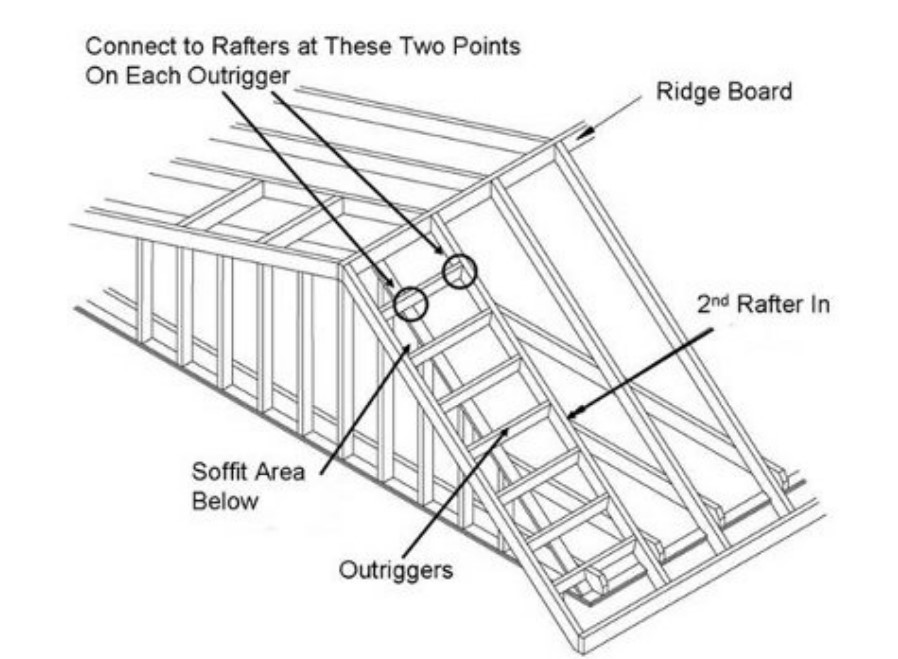
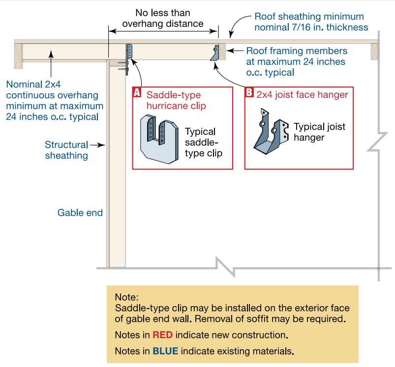
Provide structural supports that soffit panels can be nailed to at no less than 12 inches apart.
Image
Image

Image
Image
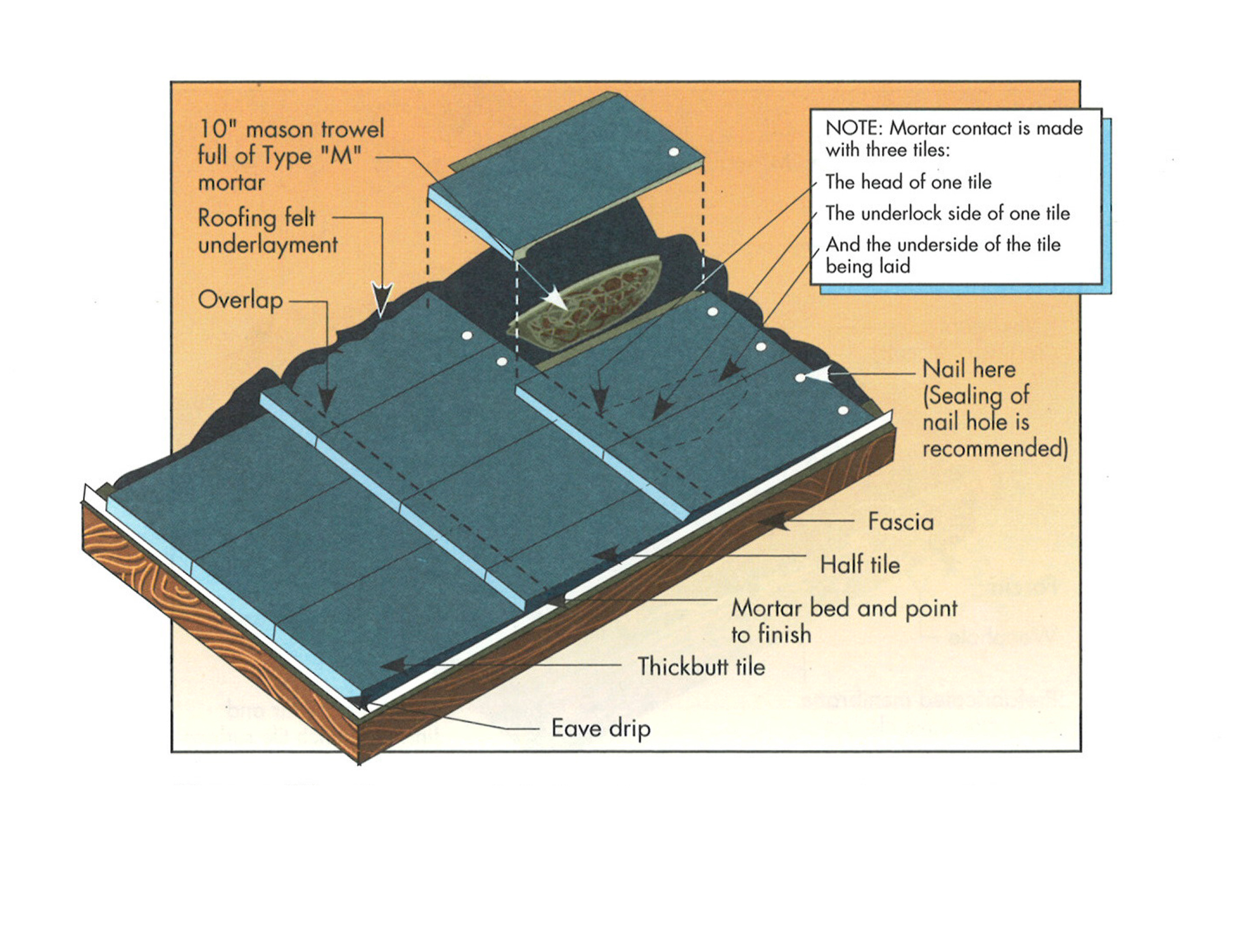
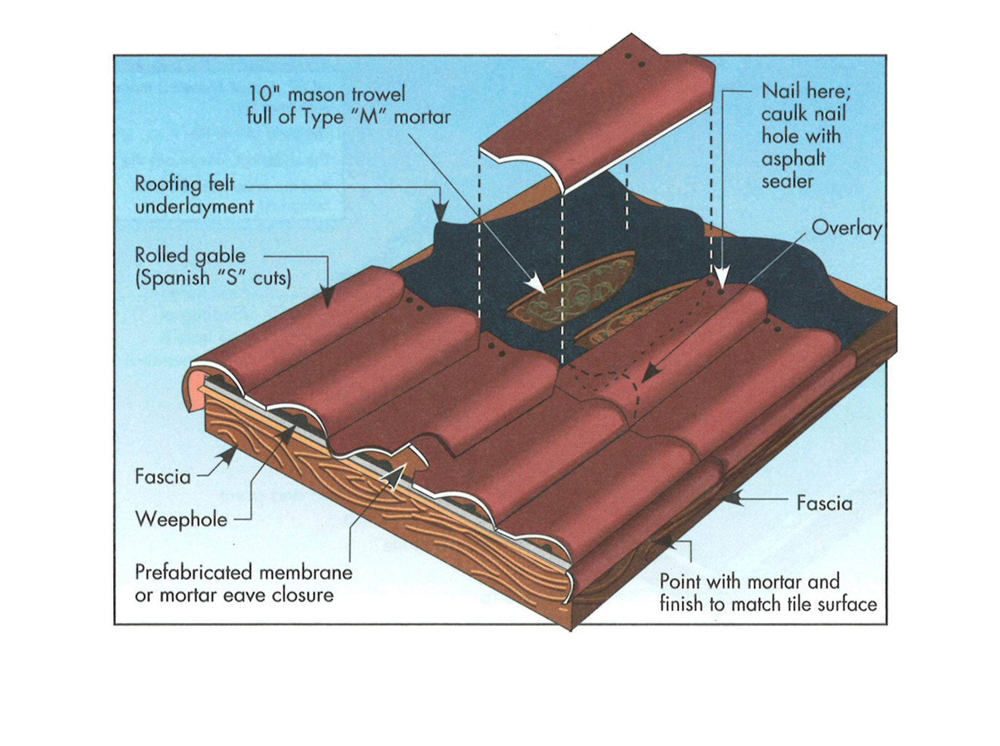
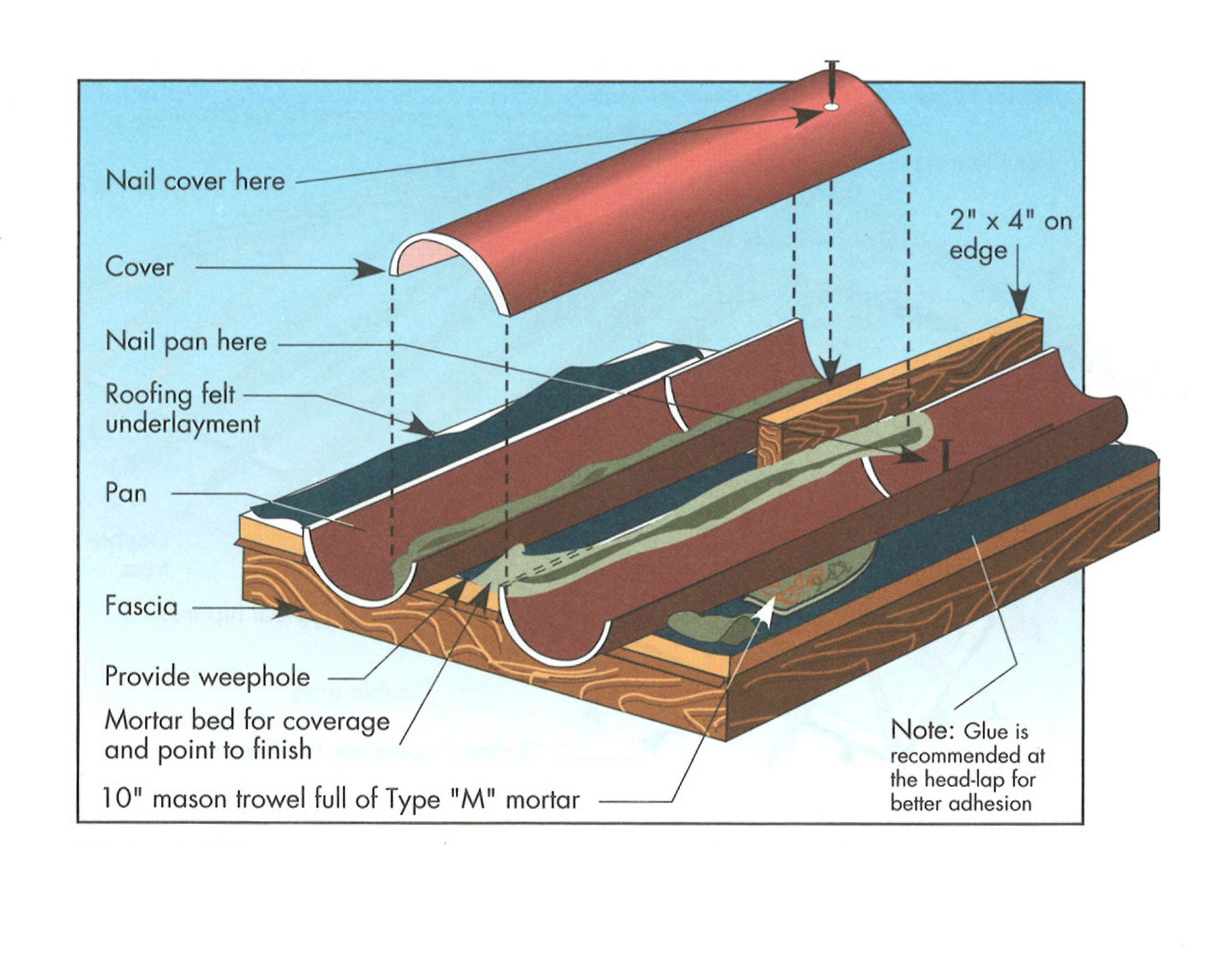
Recommended tile and mortar placement for extruded concrete flat tile roofing system
Image

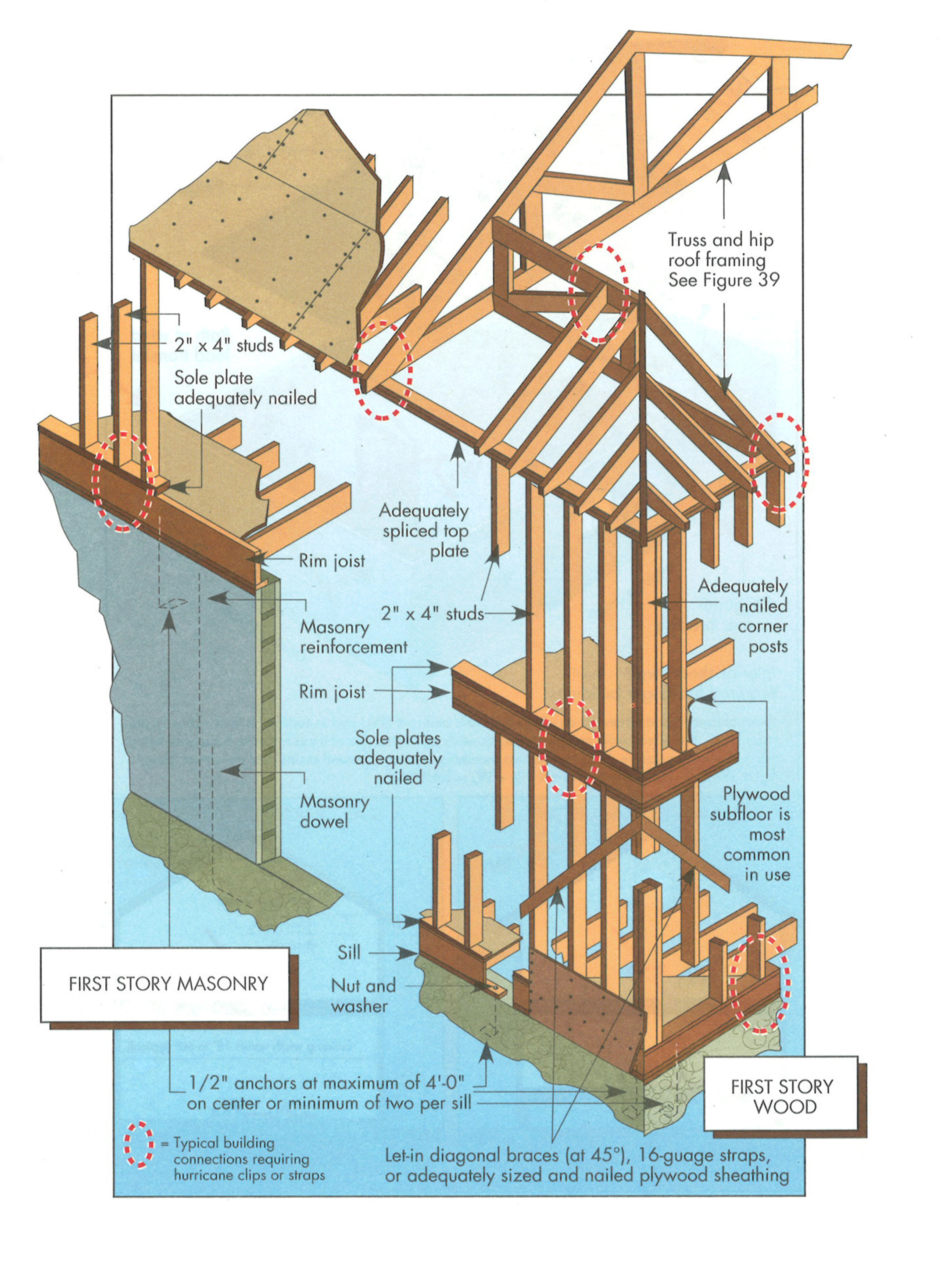
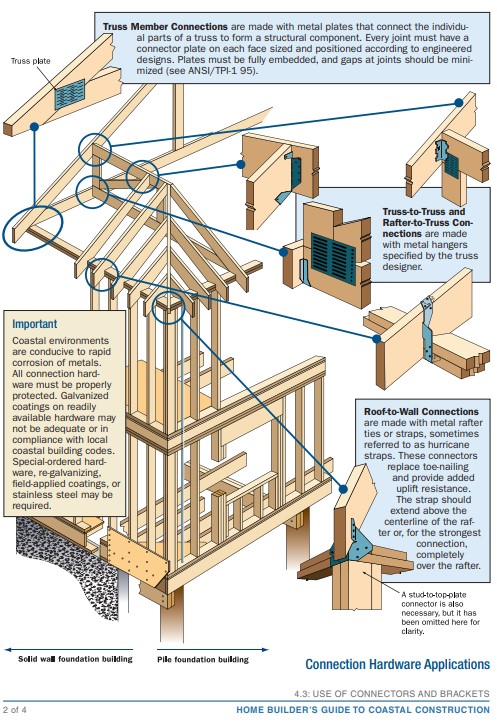
Right - A continuous load path connects the roof and wall framing to the foundation.
Image
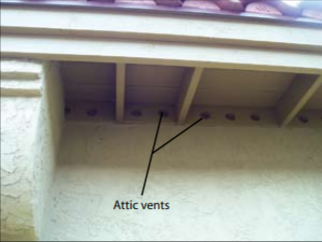
Right - An unvented attic with no soffit vents, borate-treated fascia board, metal drip edge, and concrete block construction on this south Florida home help make it resistant to hurricanes, pests, and wind-born wildfire embers.
Image
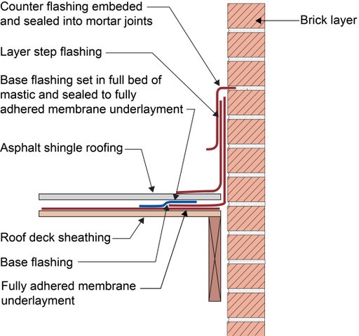
Right - Counterflashing tops a layer of step flashing which comes down above the asphalt shingle and a layer of L-shaped base flashing which comes down and extends below the shingle; the base flashing is adhered to the roof underlayment with mastic, shown
Image
Image
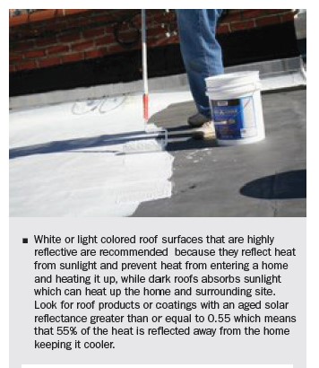
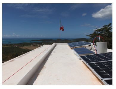
Right - In hot climates, paint flat roofs light colors to reflect solar heat gain.
Image
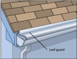
Right - Leaf guards allow rainwater into the gutter but keep combustible debris out, increasing the home's resistance to wildfires.
Image
Right - Metal drip edge on this south Florida CMU home protects the top of the fascia and edge of the roof deck from water, wind-blown rain and embers, and insects.
Image
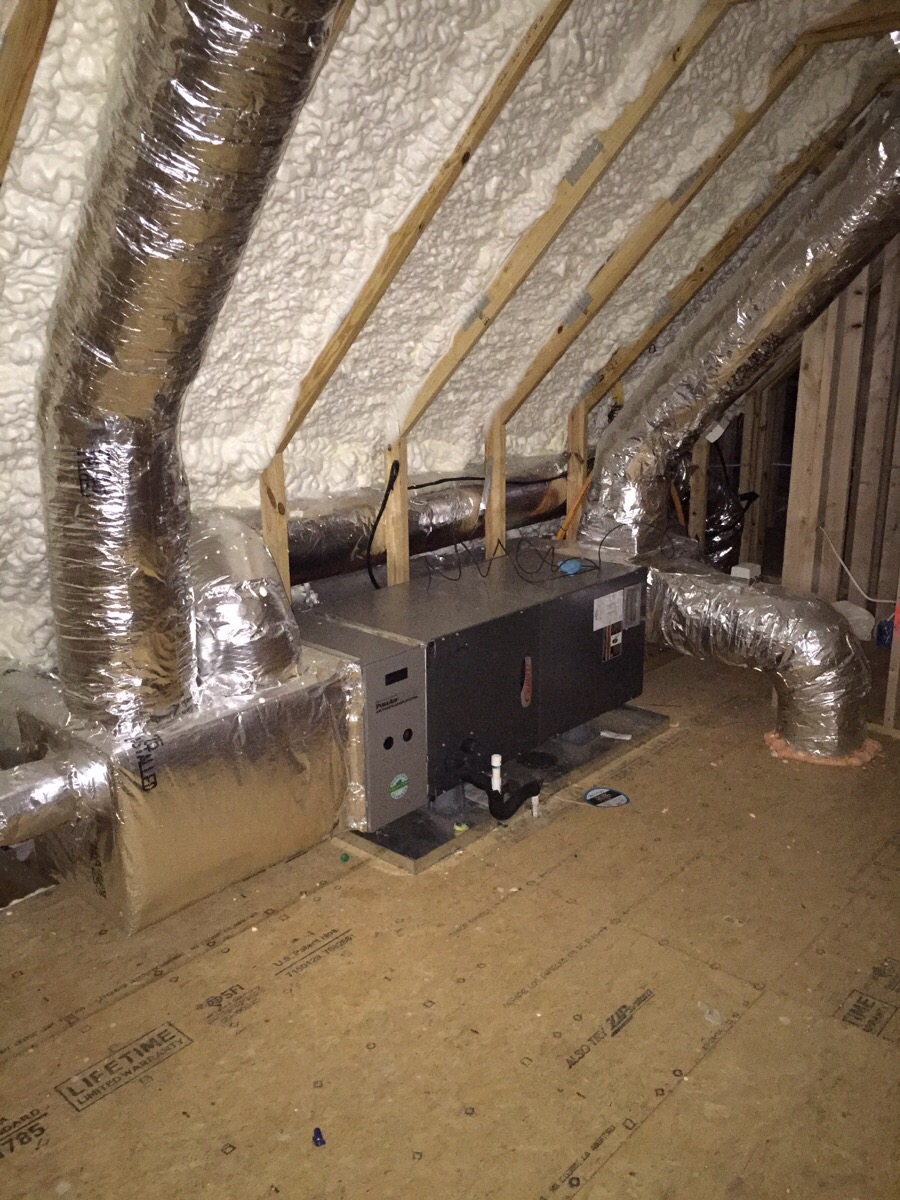
Right - Open-cell polyurethane spray foam to R-28 on underside of roof turns new attic into conditioned space for HVAC.
Image
Right - Pieces of metal flashing are installed under each tile course along the valley centerline to prevent debris accumulation between and below concrete roof tiles.
Image
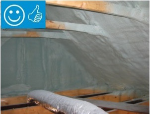
Right - Spray foam insulation has been sprayed onto the underside of the sloped roof and the gable end wall to provide a sealed, insulated attic for housing the HVAC ducts
Image
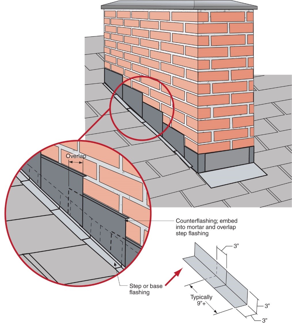
Right - Step flashing along a chimney is integrated in a layered manner with asphalt shingle roofing and topped with counterflashing that is embedded into brick mortar joint above
Image

Right - The wall framing is connected to roof framing with metal ties for hurricane-resistant construction.
Image
Right - These raised heel roof trusses provide 16 inches of space over the outer walls for full insulation coverage at the attic perimeter.
Image
Right - This concrete roof is properly attached and reinforced to withstand hurricane winds.
Image
Right - This roof has a low gable and is secured to the wall framing to resist wind uplift.
Image
Image
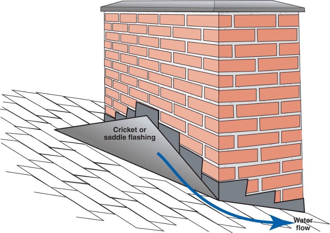
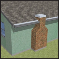
Right – A chimney cricket is installed and flashed to direct rainwater around the chimney
Image
Image
Image
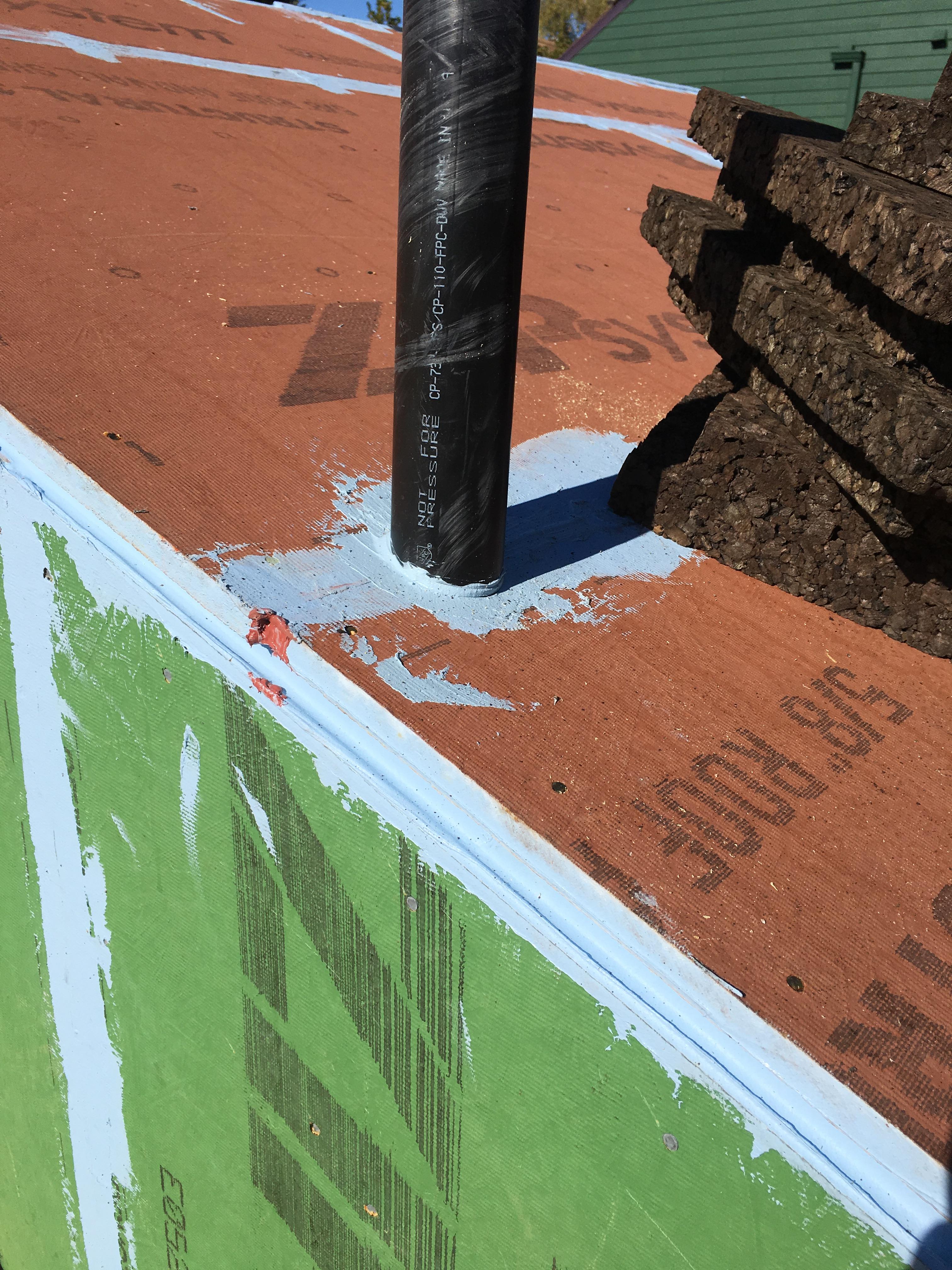
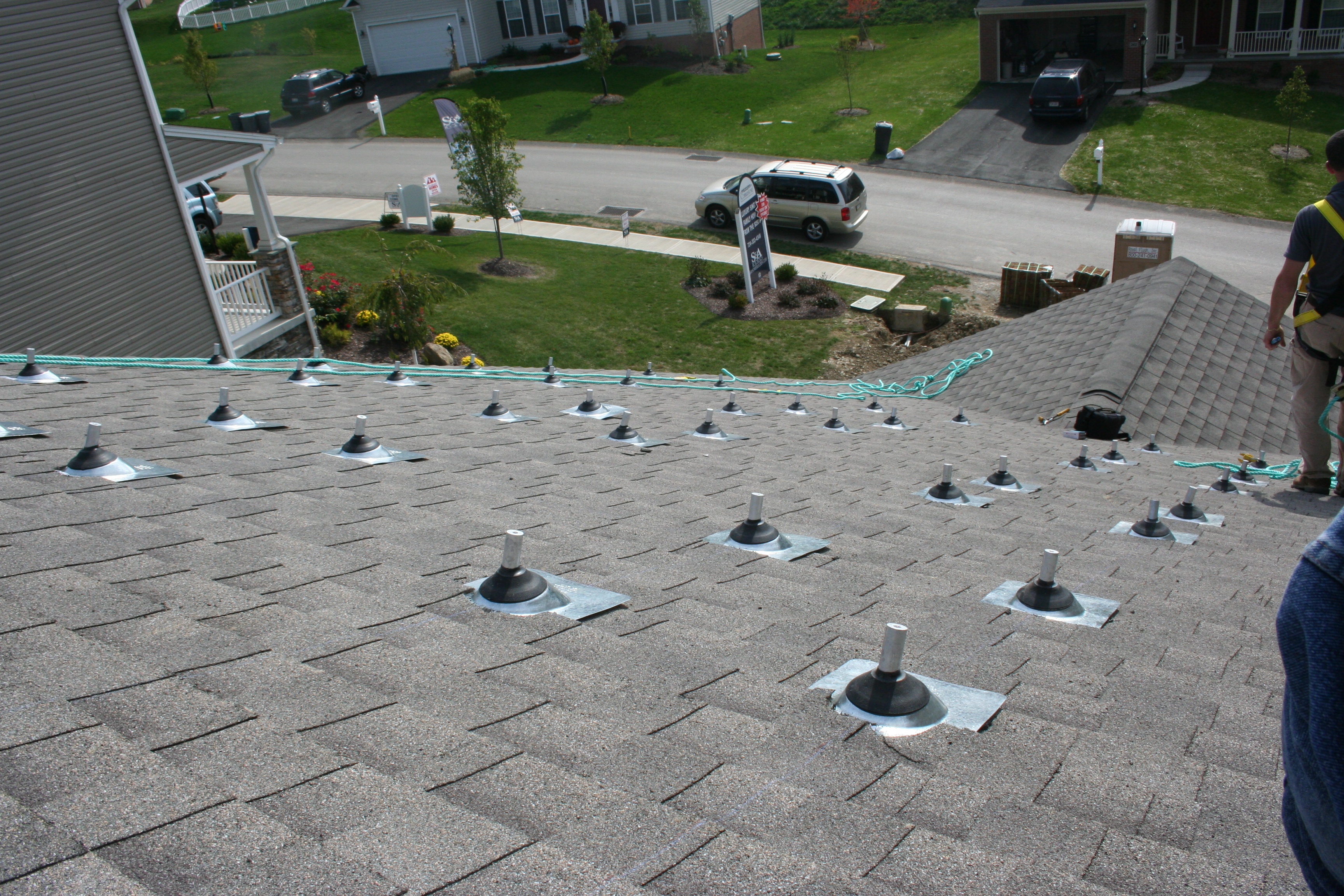
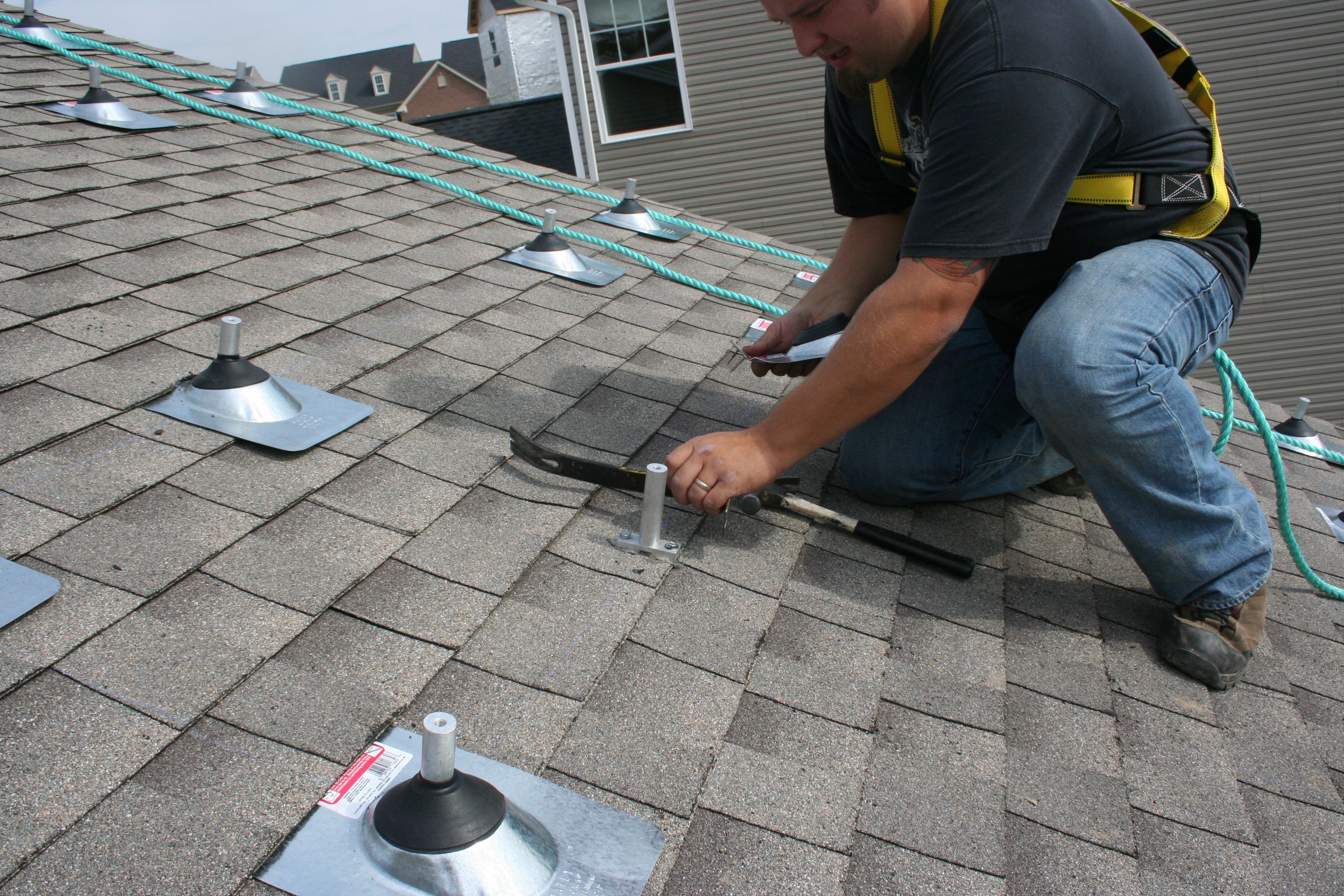
Right – All penetrations through the roof decking are sealed with paint-on flashing.
Image
Image
Image
Image
Right – Closed-cell polyurethane foam is sprayed on the underside of the roof deck to provide structural connections and seal seams in the sheathing to increase wind resistance
Image
Image
Image
Image
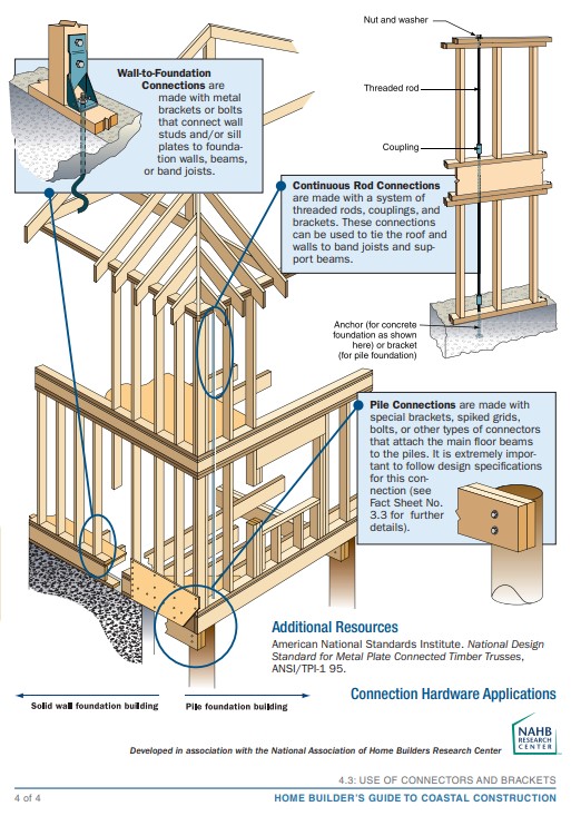
Right – Examples of wall stud to sill plate and foundation and wall rod connectors and brackets.
Image
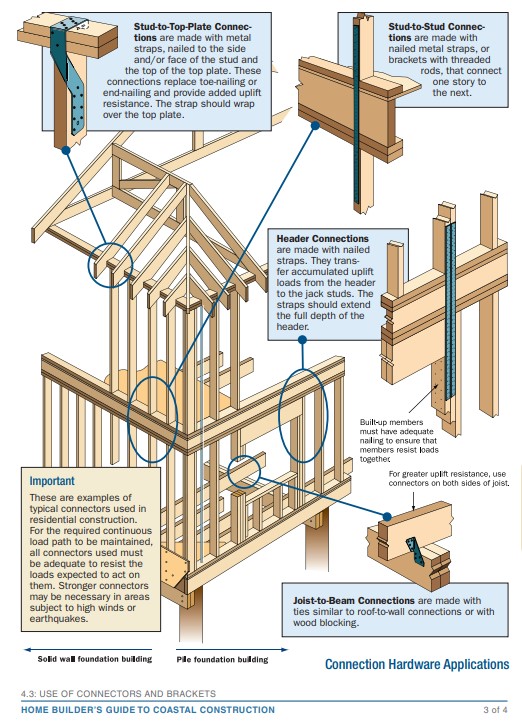
Right – Examples of wall stud to top plate and stud to rim joist framing connectors and brackets.
Image
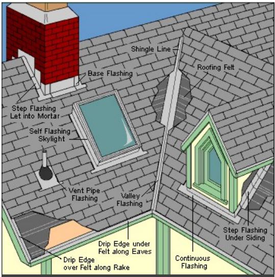
Right – Flashing is installed around chimney, skylight, vents, dormers, in valleys and at eaves
Image
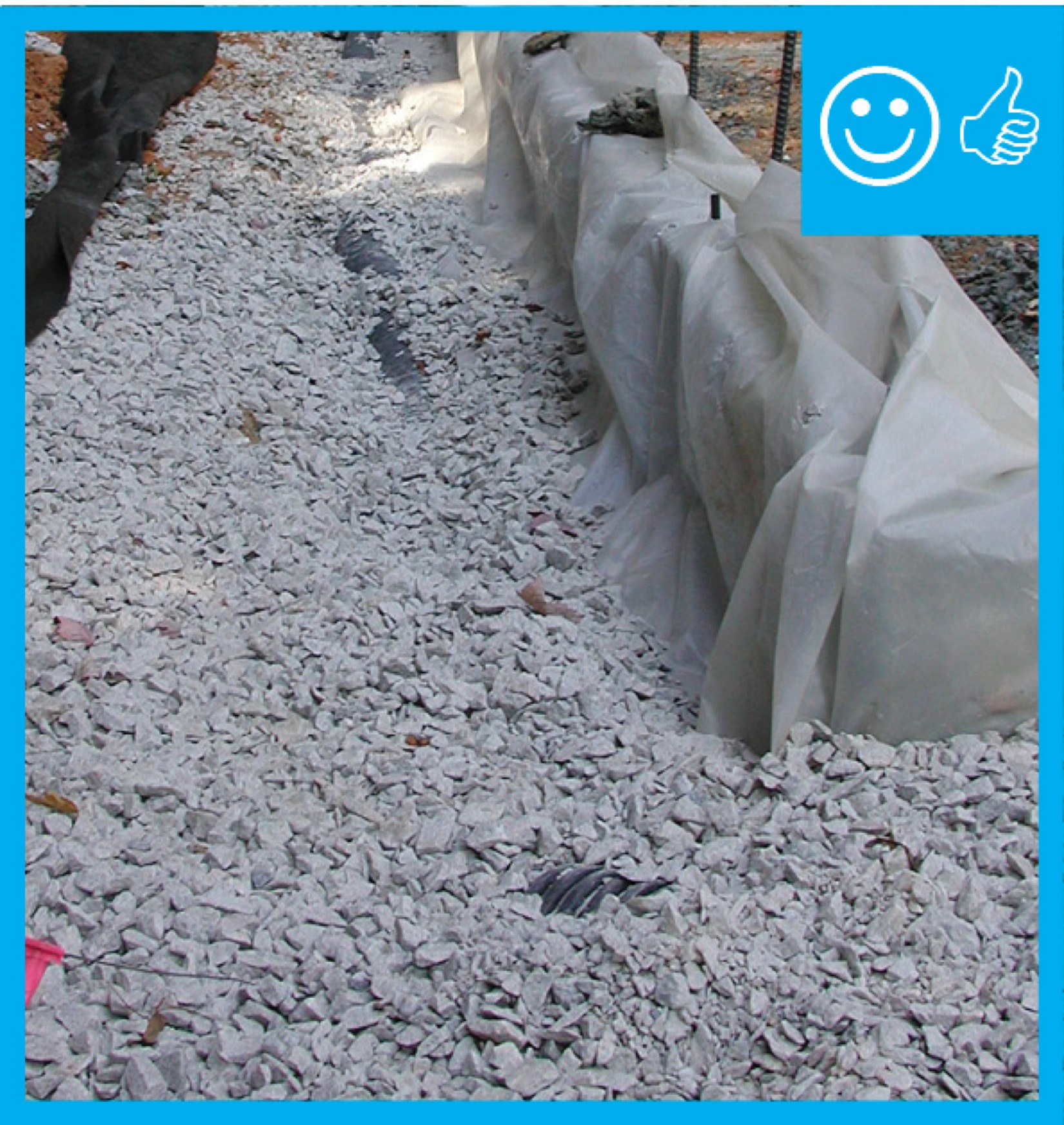
Right – House without gutters has waterproof liner, drain tile, and gravel bed extending more than 5 feet from foundation
Image
Image
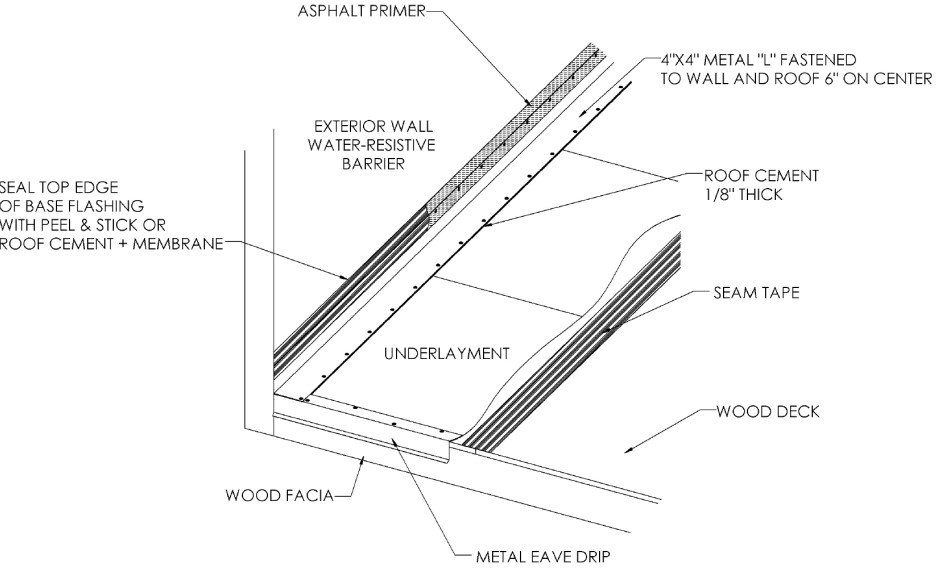
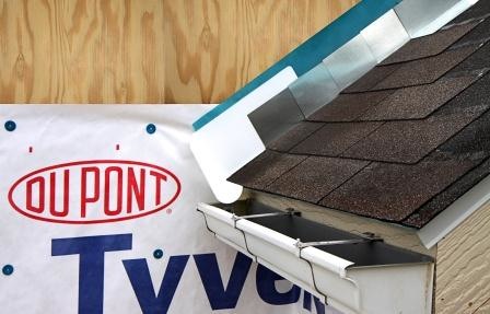
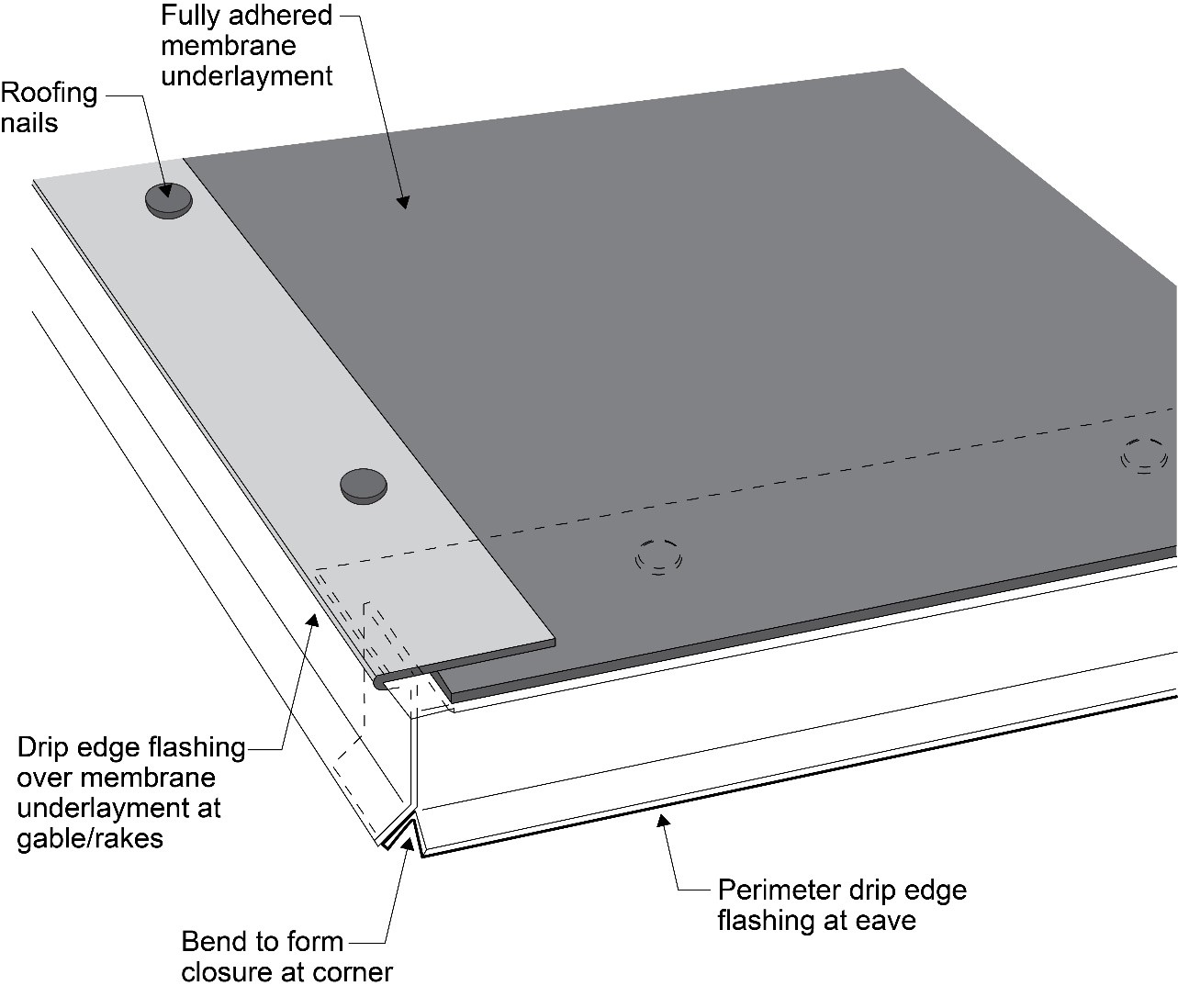
Right – If drip edge flashing is installed over fully adhered roof membrane at eaves, use flashing cement to seal the upper edge of the flashing
Image
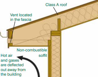
Right – In wildfire prone areas, using a flat soffit with venting on the fascia instead of an angled soffit with down-facing venting reduces the risk of catching rising embers.
Image
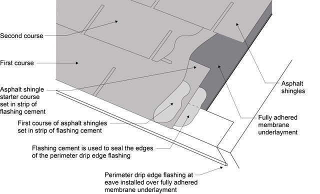
Right – Install asphalt shingles over a starter strip set in an 8-inch strip of flashing cement
Image
Image
Image
Image
Image
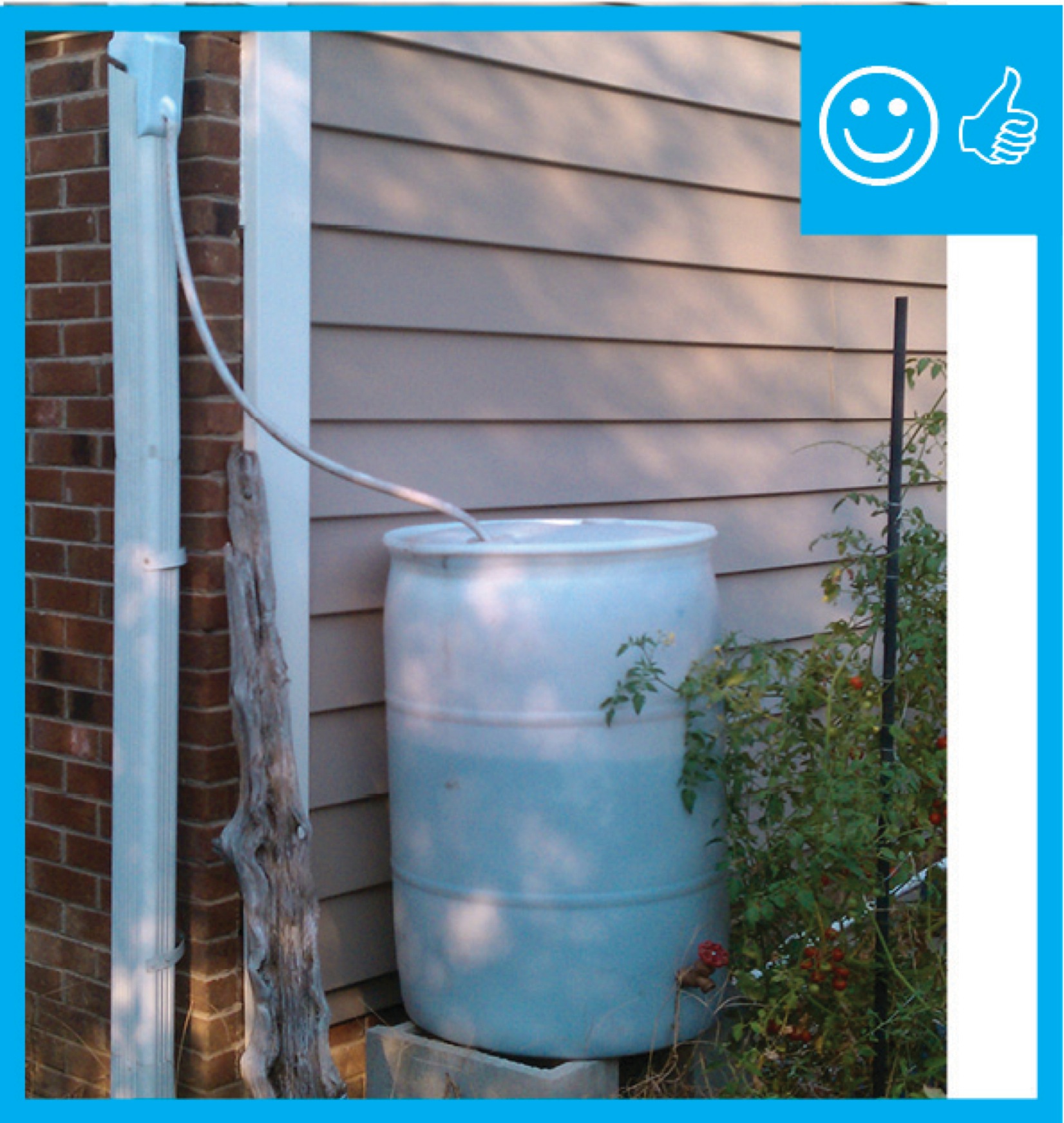
Right – Rain barrel installed with an overflow spout terminating at least 5 feet from foundation
Image
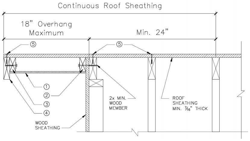
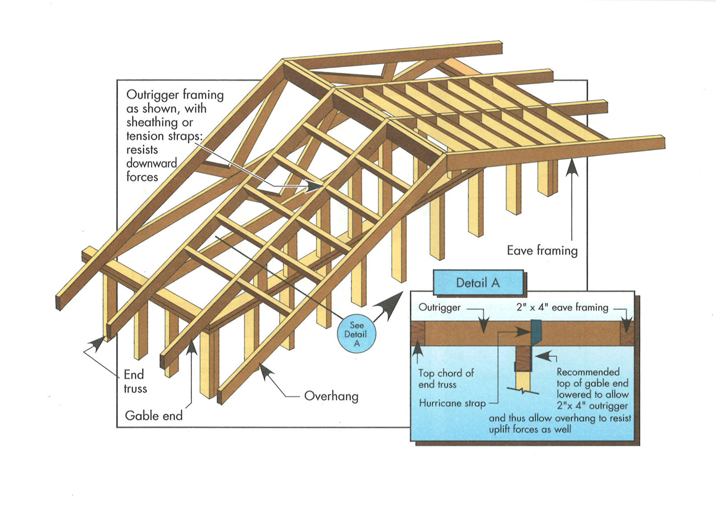
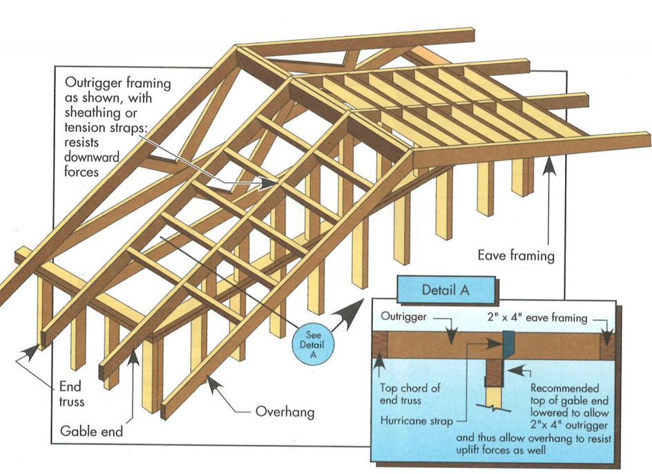
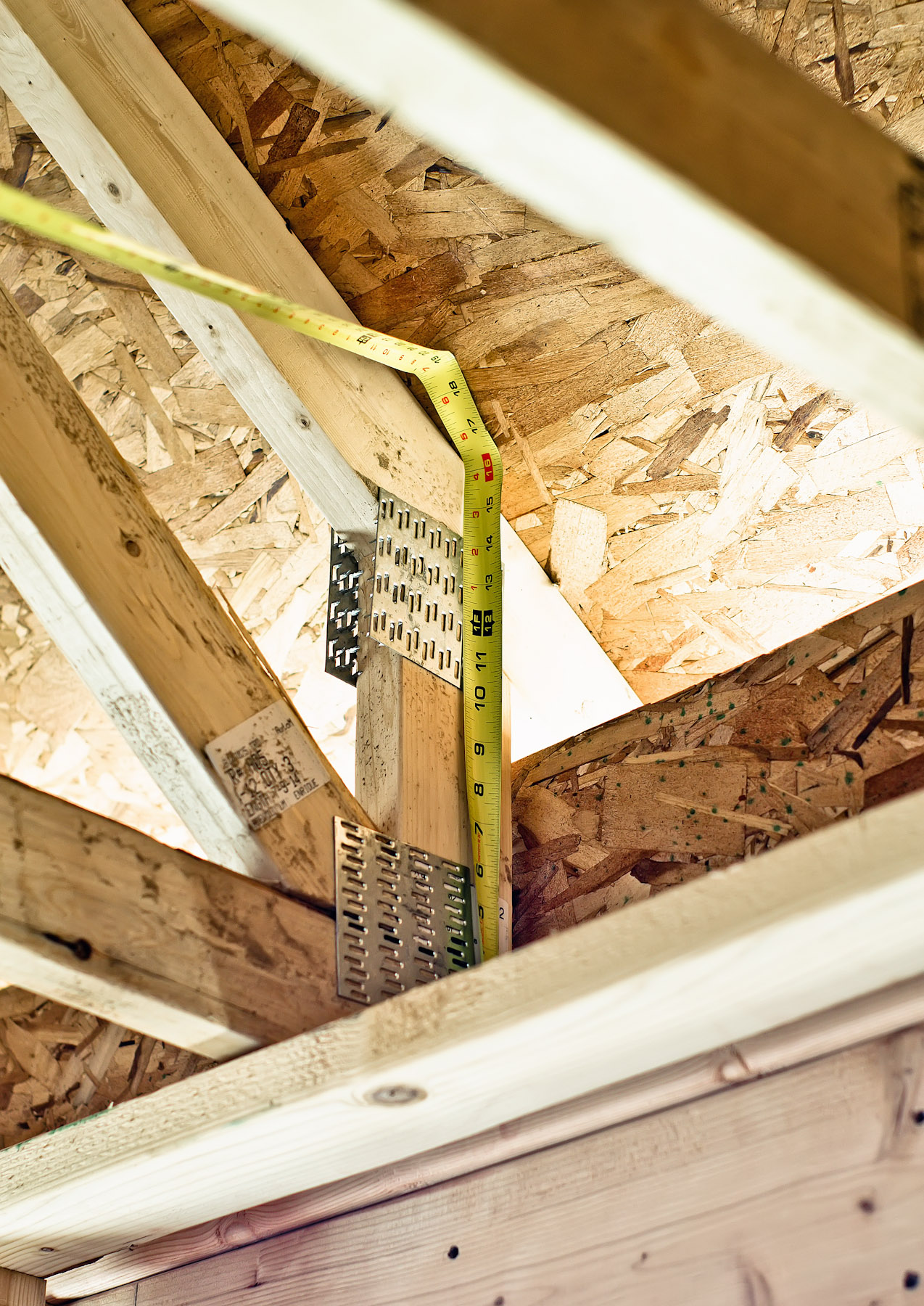
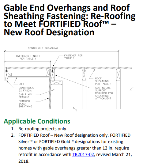
Right – Retrofit Specification for installing roof sheathing an 18-inch gable end overhang
Image
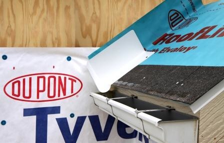
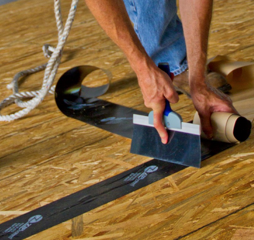
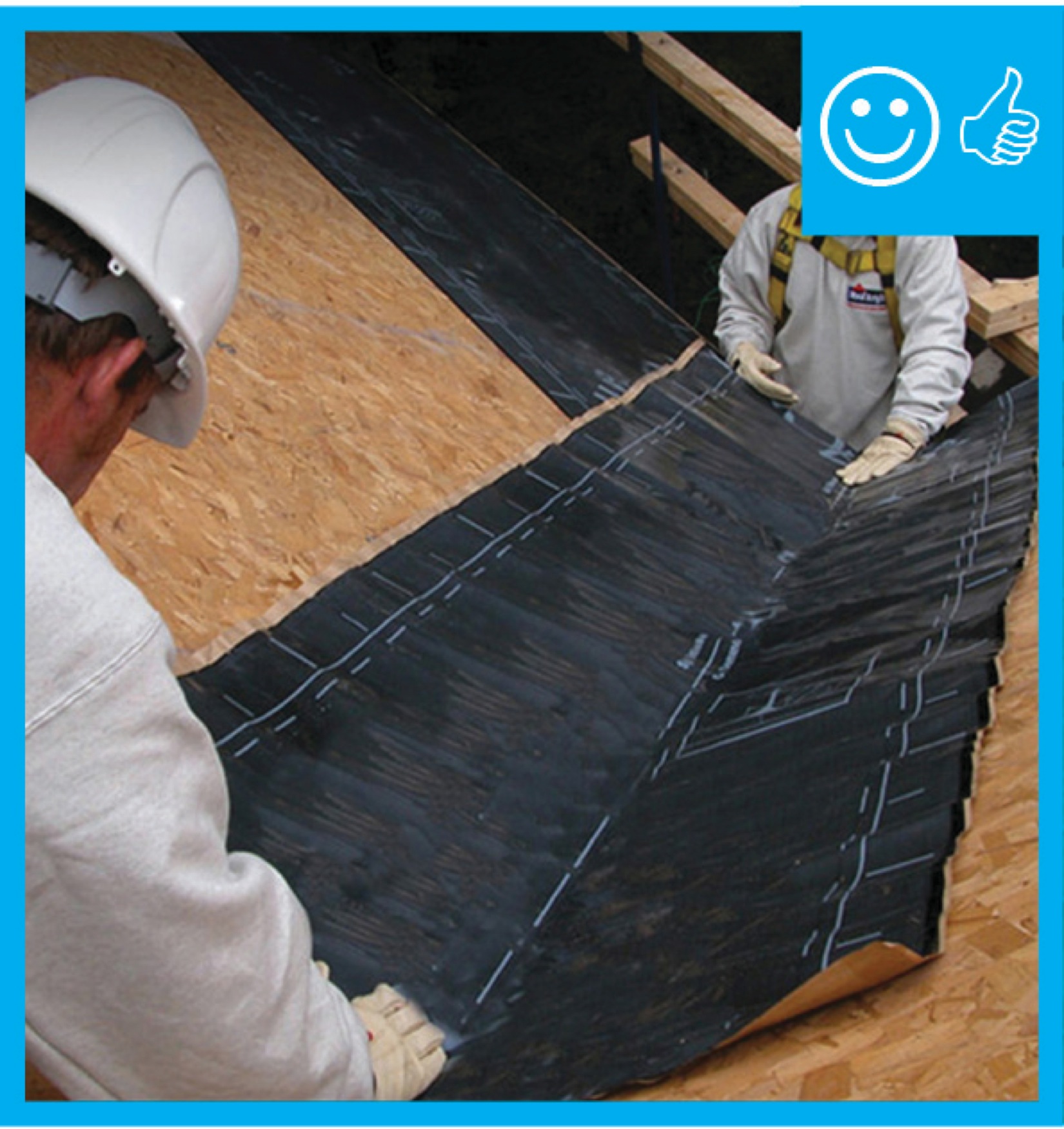
Right – Roof underlayment is fully adhered and roof deck seams are sealed so roof is resistant to high-wind events
Image
Right – Roof underlayment is fully adhered and roof deck seams are sealed so roof is resistant to high-wind events
Image
Image

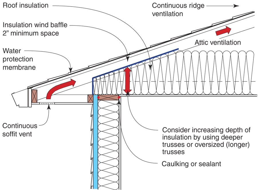
Right – Sheathing extends to rafters adding strength to soffit, baffles keep attic insulation from vent to maintain air flow
Image
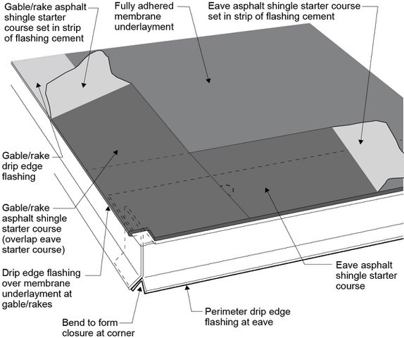
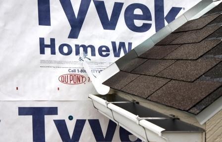
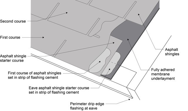
Right – Start asphalt shingle installation with a starter strip set in an 8-inch strip of flashing cement
Image
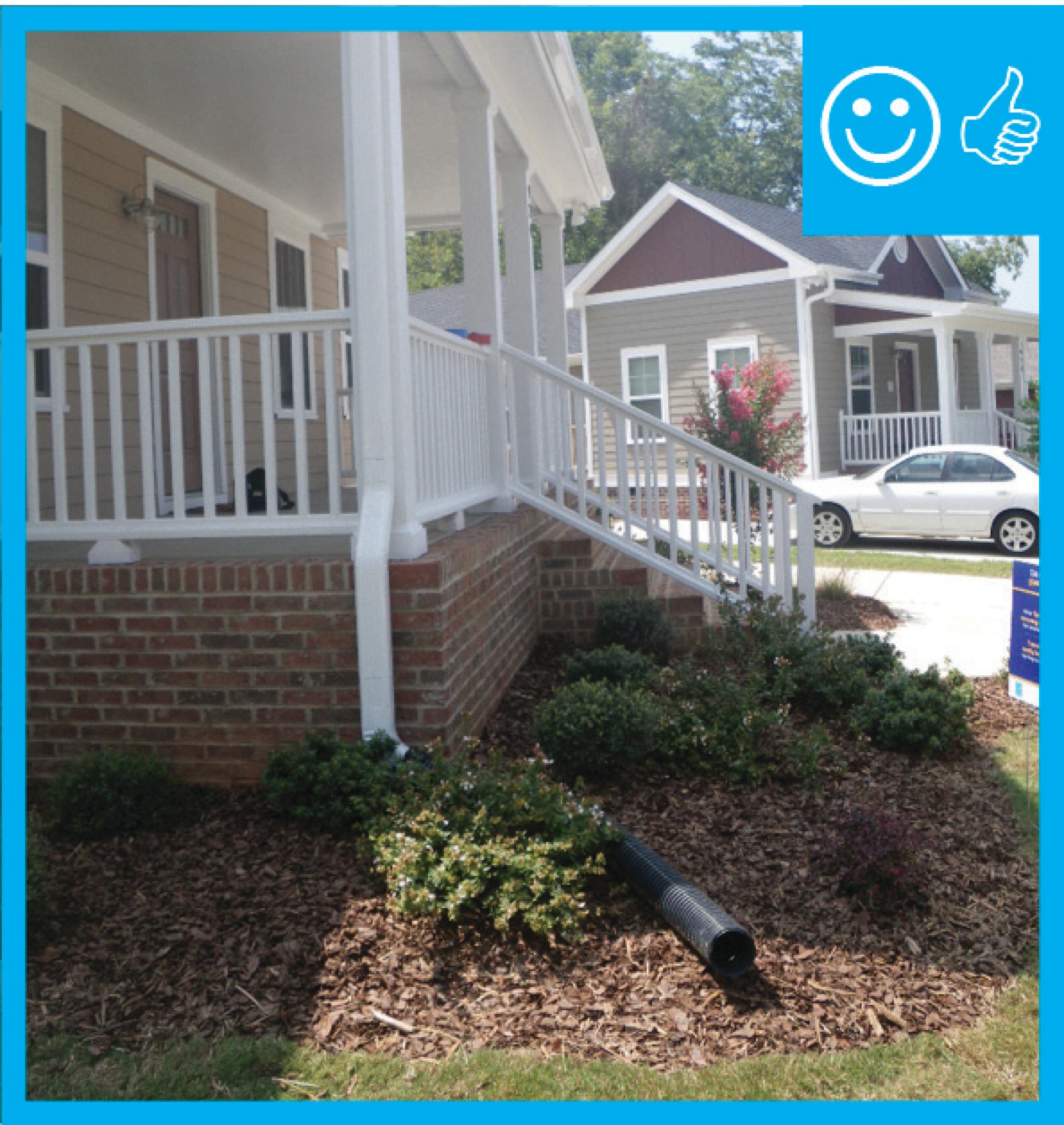
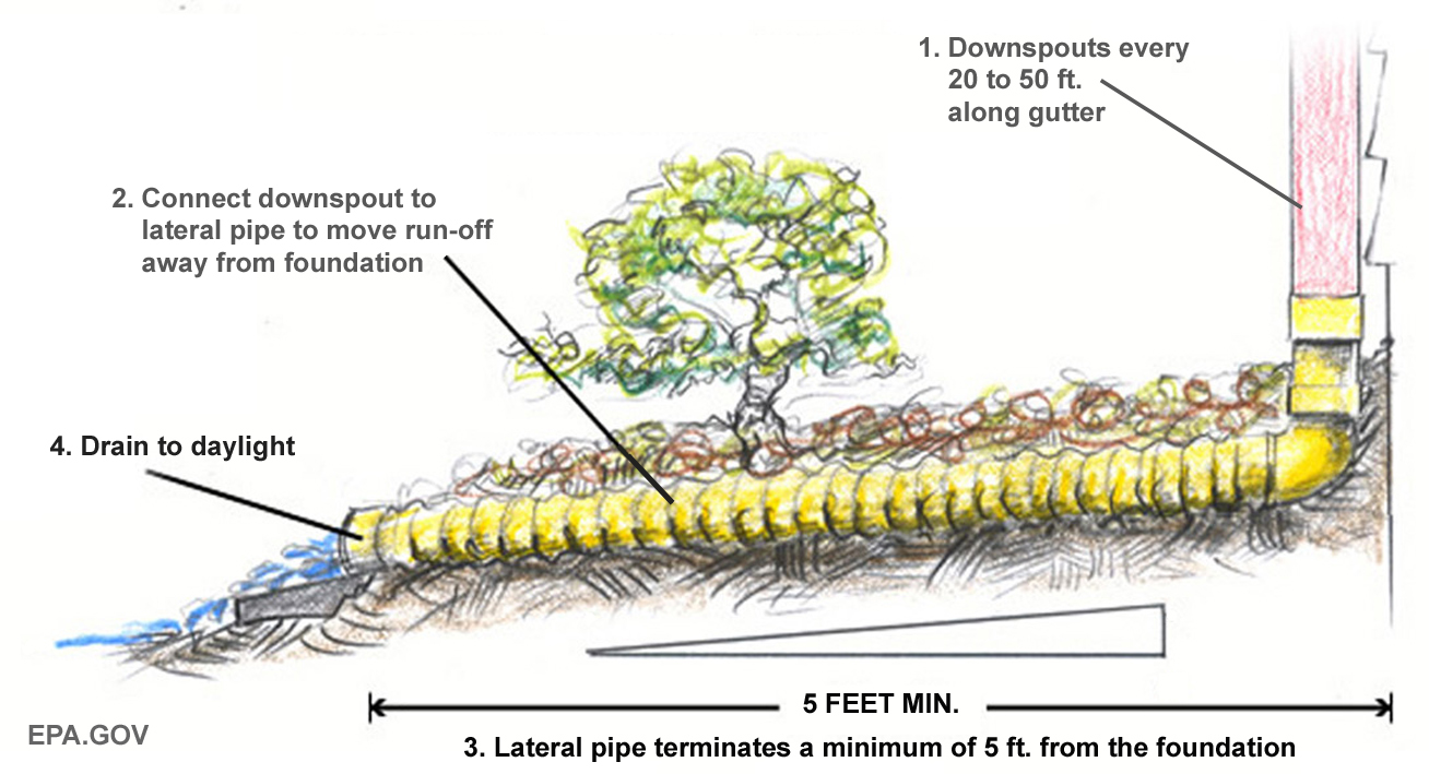
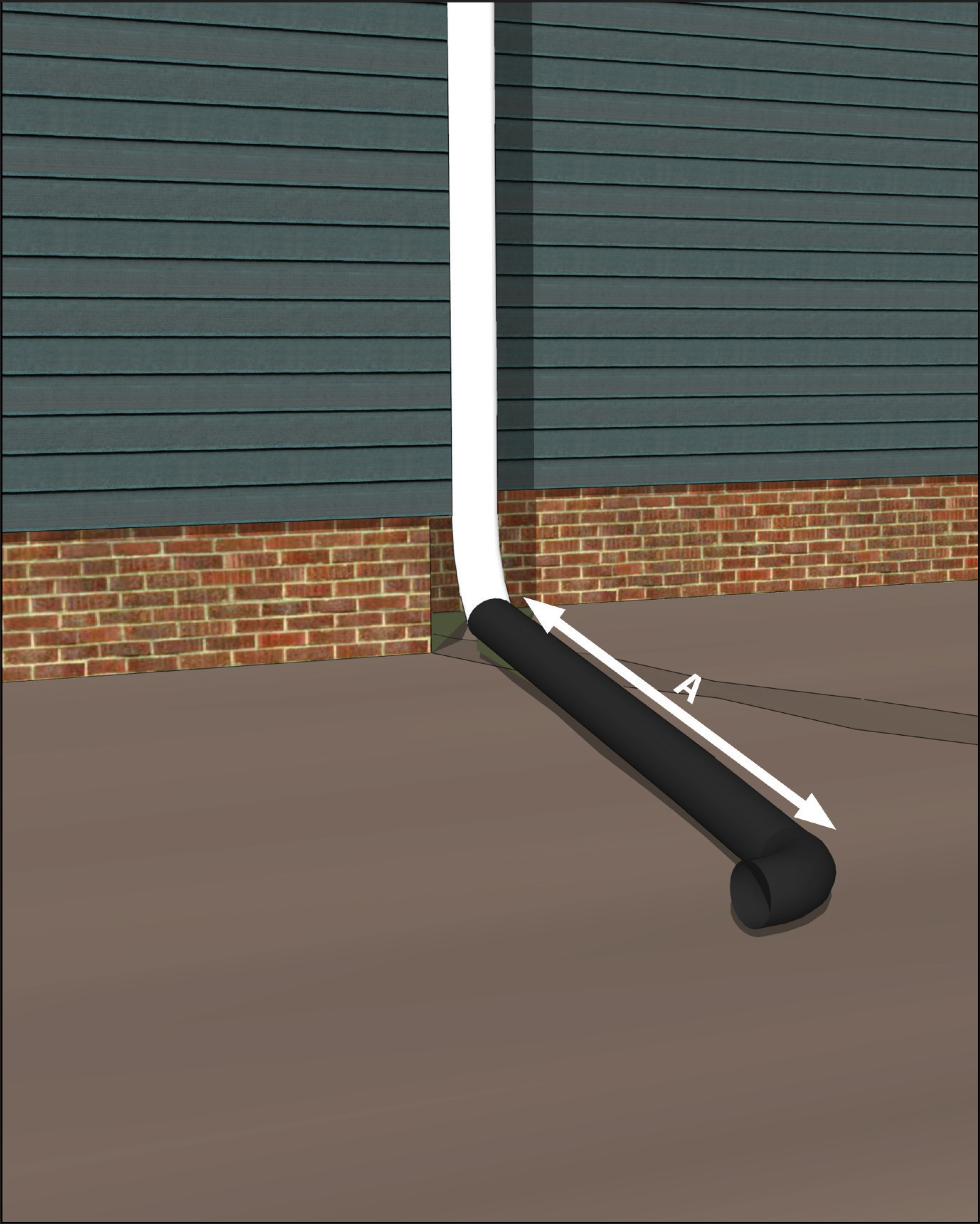
Right – The downspout pipe is far enough away from the foundation to prevent moisture problems
Image
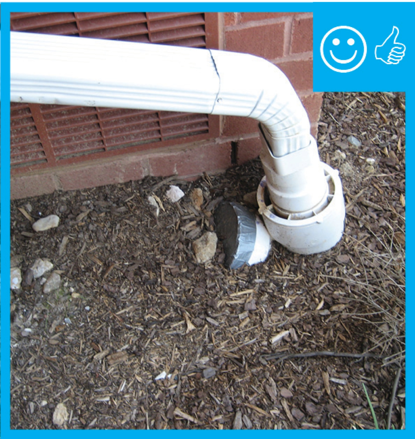
Right – The downspout terminates into a catchment system that moves water away from the foundation of the house
Image
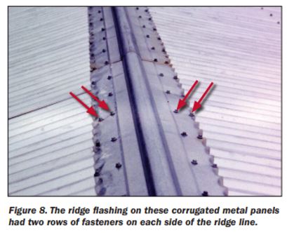
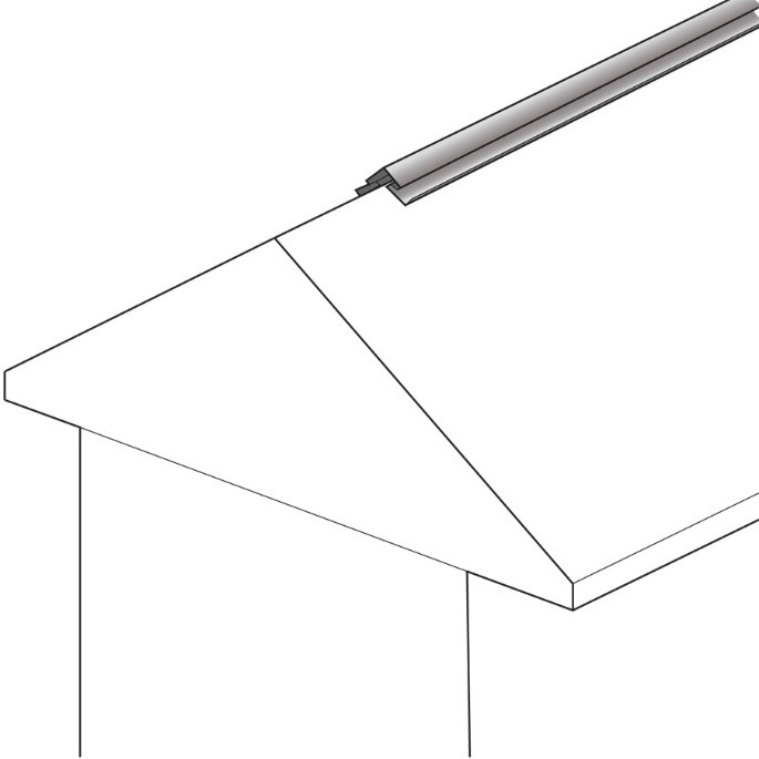
Right – The ridge flashing is secured with two rows of fasteners on each side of the ridge line
Image
Right – The roof membrane is fully adhered and deck seams are sealed so the membrane will not flutter and fail due to negative pressure from high winds
Image
Image
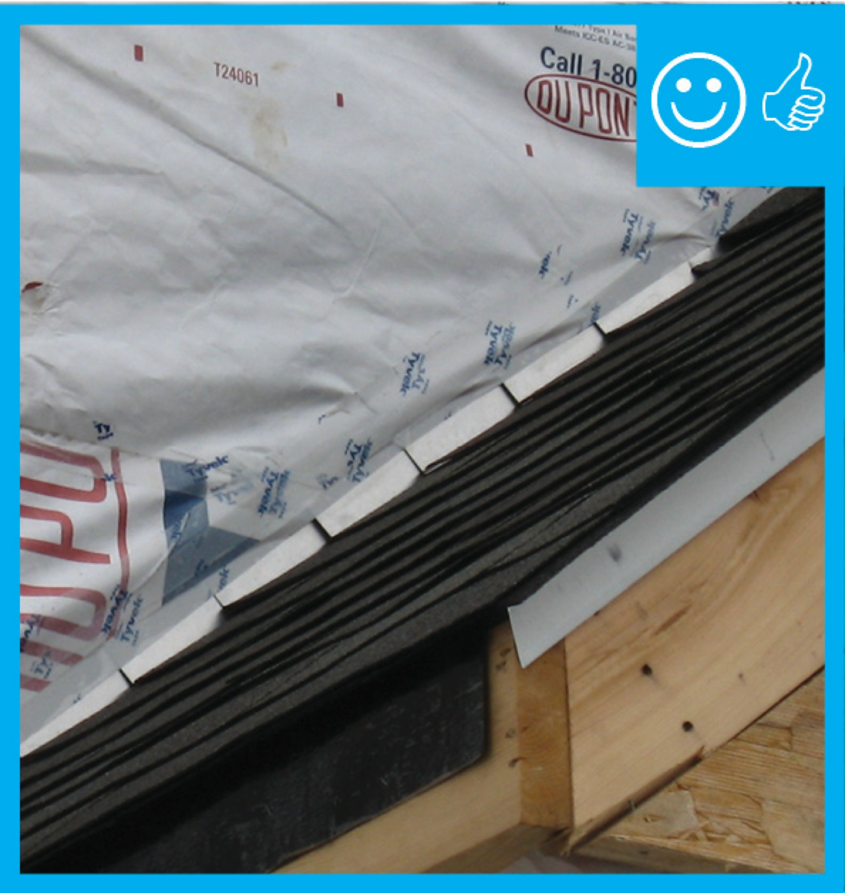
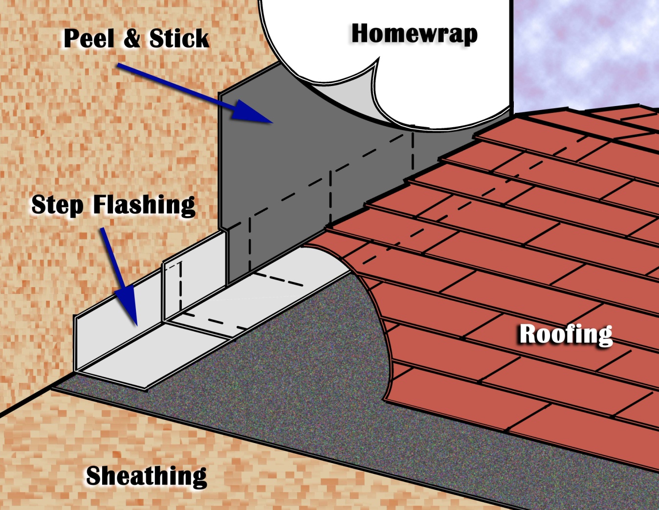
Right – The water-resistant barrier is layered over the step flashing to provide a complete drainage system
Image
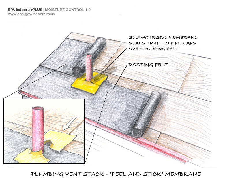
Right – There is a properly installed and layered self-sealing bituminous membrane at the roof penetration
Image
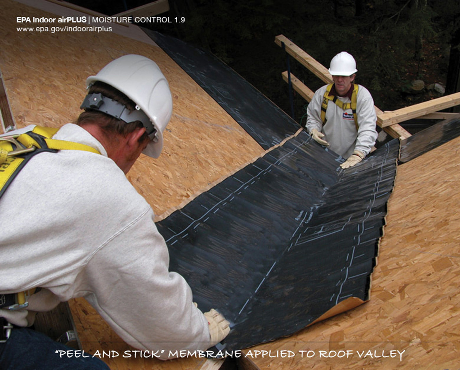
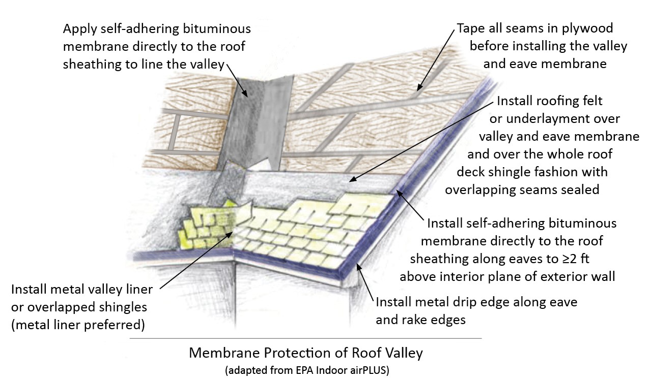
Right – There is a self-sealing bituminous membrane installed at the valley of the roof prior to the roof felt
Image
Right – This fire-rated wall assembly uses exterior gypsum board and an exterior siding of fiber-cement or metal to increase fire resistance.
Image
Image
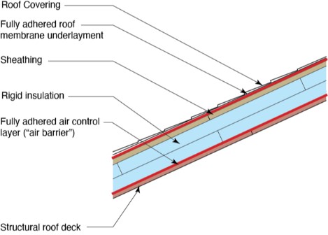
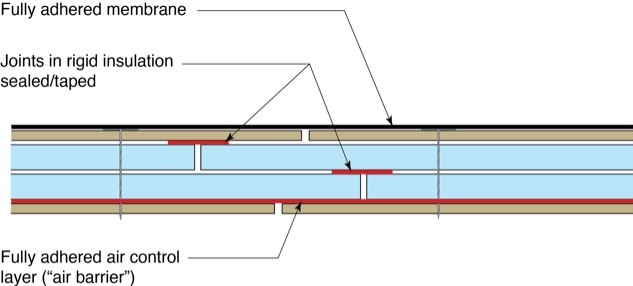
Right – This low-slope flat roof assembly has continuity of both the air and water barriers
Image
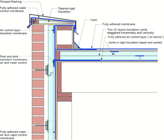
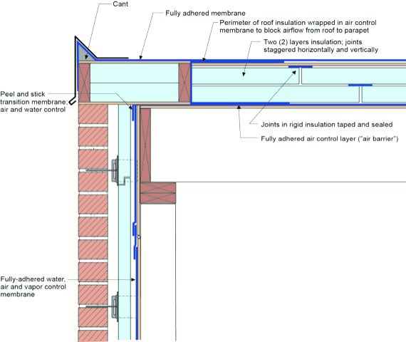
Right – This low-slope roof and parapet assembly has continuity of both the air and water barriers
Image
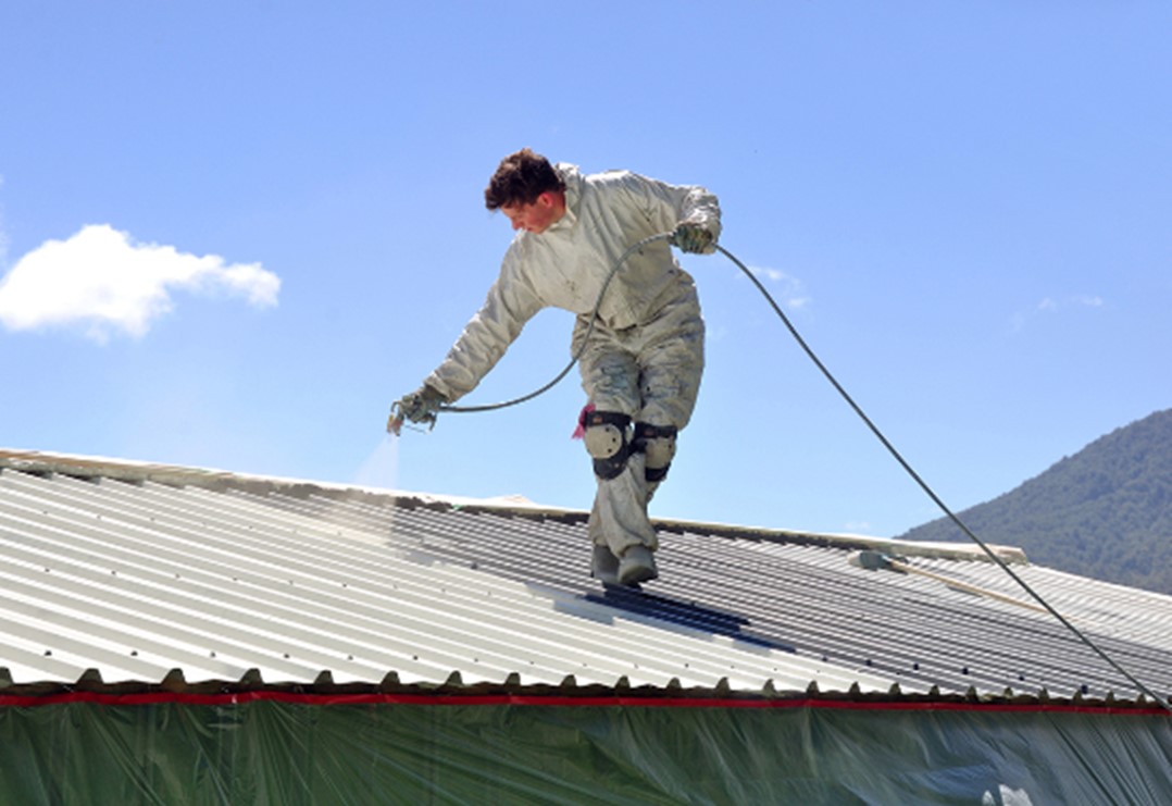
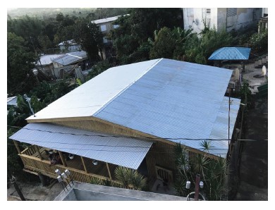
Right – This metal roof is being coated with a cool (high SRI) coating to reduce solar heat gain
Image
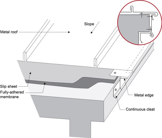
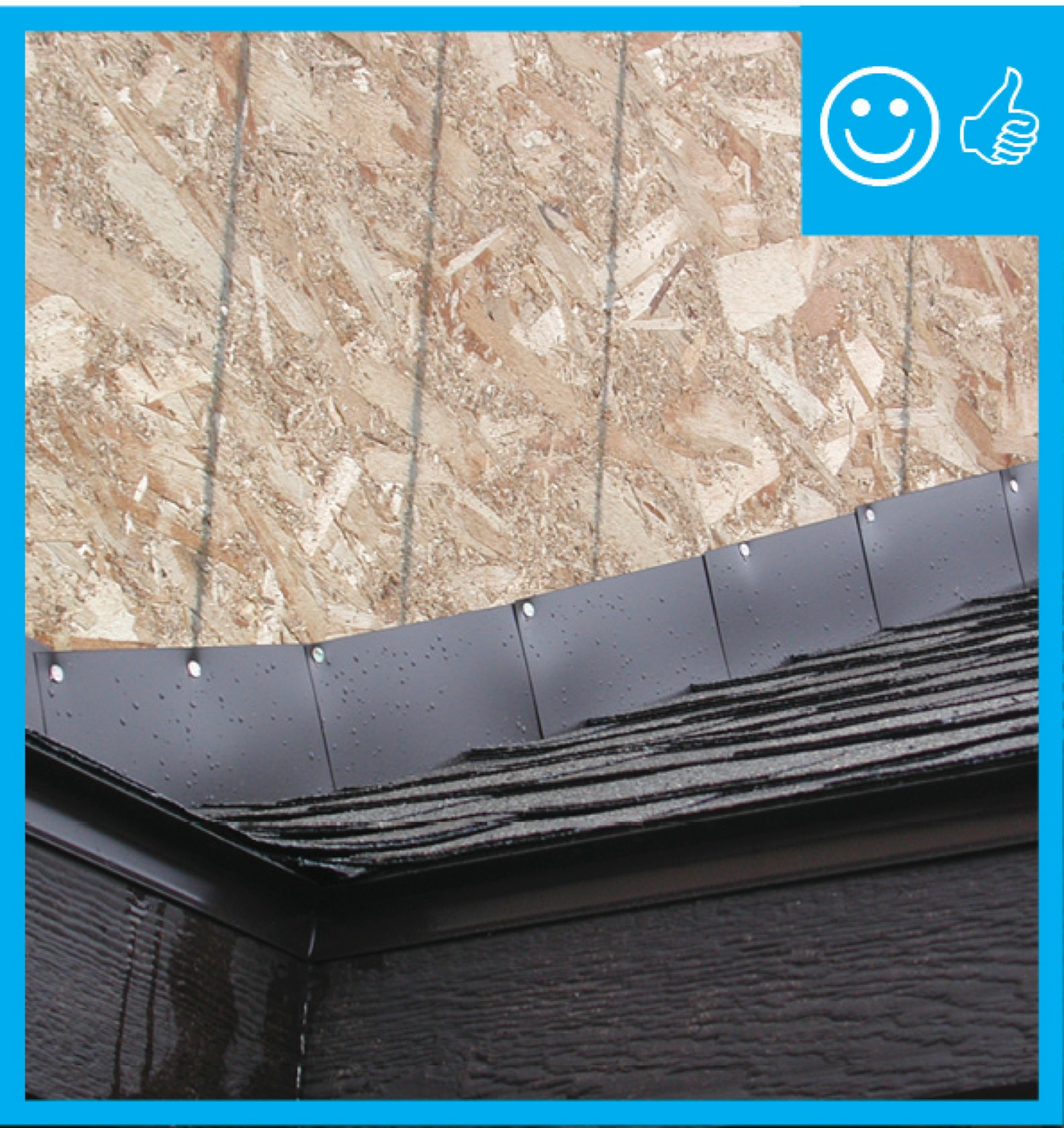
Right – Under metal roofing, sheathing is protected by metal edging over a fully adhered membrane and a slip sheet of loose laid building paper
Image
Roof dormer is braced with steel connectors and strapping to increase its resistance to uplift
Image
Image
Image
Image
Image
Image
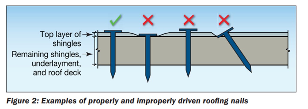
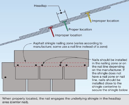
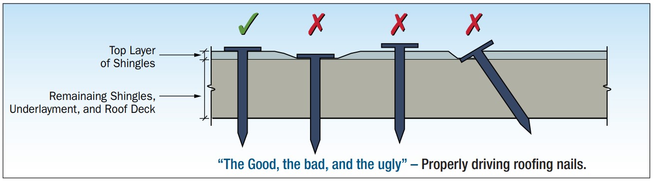
Roofing nails should be driven in straight and flush, not overdriven, underdriven, or angled
Image
Image

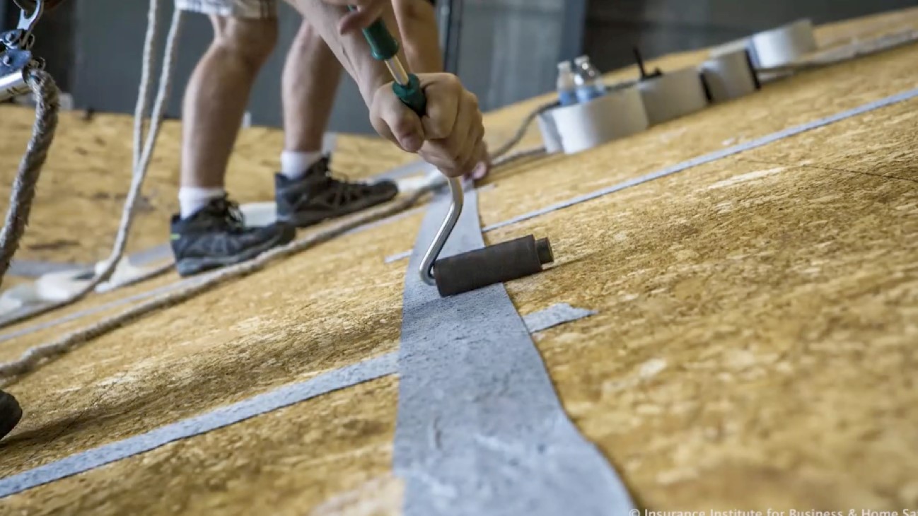
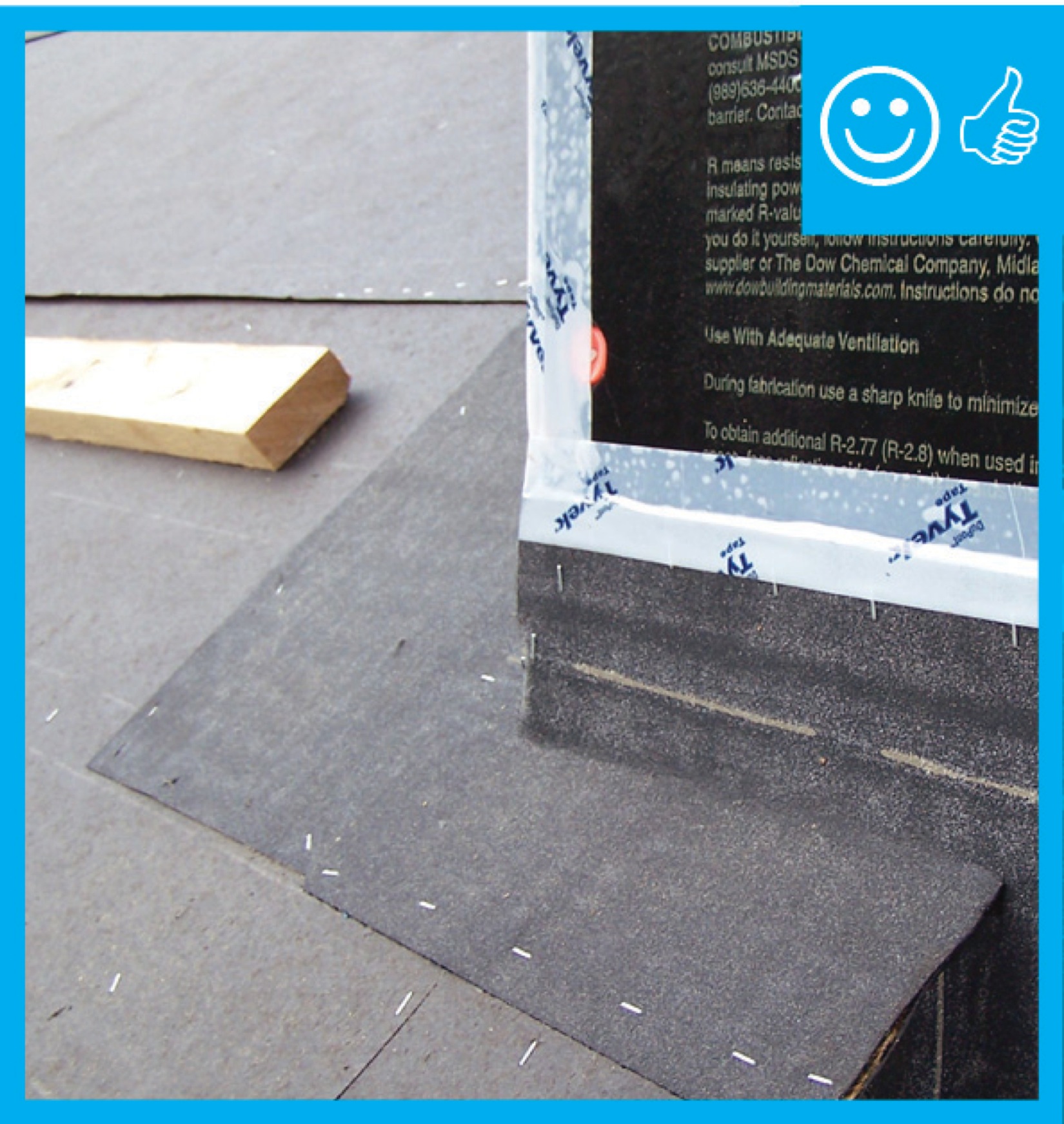
Seal the roof deck as follows: Sweep roof decking, tape seams, and cover underlayment or roofing felt as shown.
Image
Image
Image
Image
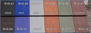
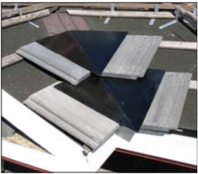
Side by side comparisons of standard roofing colors (top row) and cool colors (bottom row) shows that solar reflectance (R) can be reduced significantly using special coatings with almost no change to the color
Image
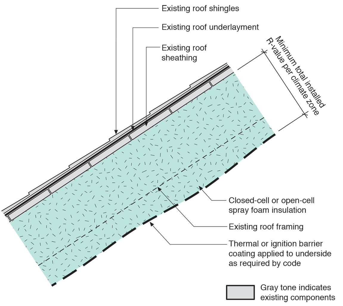
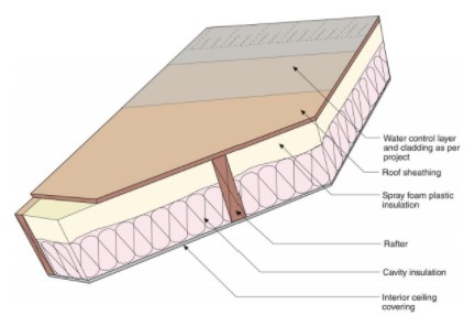
Sloped roof with cavity spray foam insulation sprayed on underside of roof deck and covered with sprayed-on thermal or ignition barrier coating.
Image
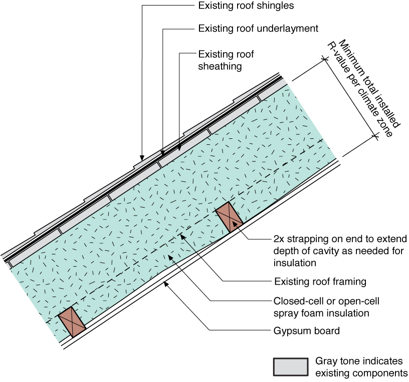
Sloped roof with cavity spray foam insulation, strapping, and gypsum board thermal barrier
Image
Image
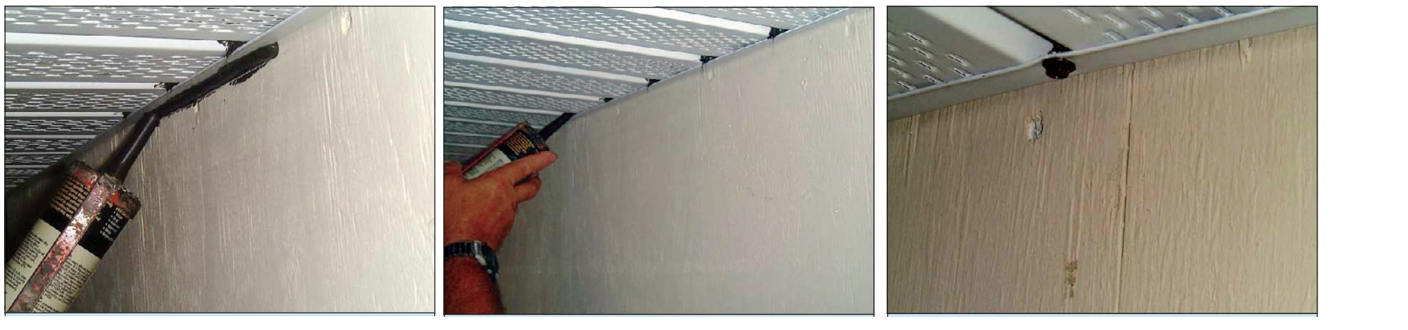
Soffits can be secured by caulking to the wall, sealing between each soffit panel and the wall channel, and screwing the wall channel to the soffit panels.
Image
Sources of heat gain in a house include solar gains, infiltration, conduction through walls and roof, occupants, and internal equipment
Image
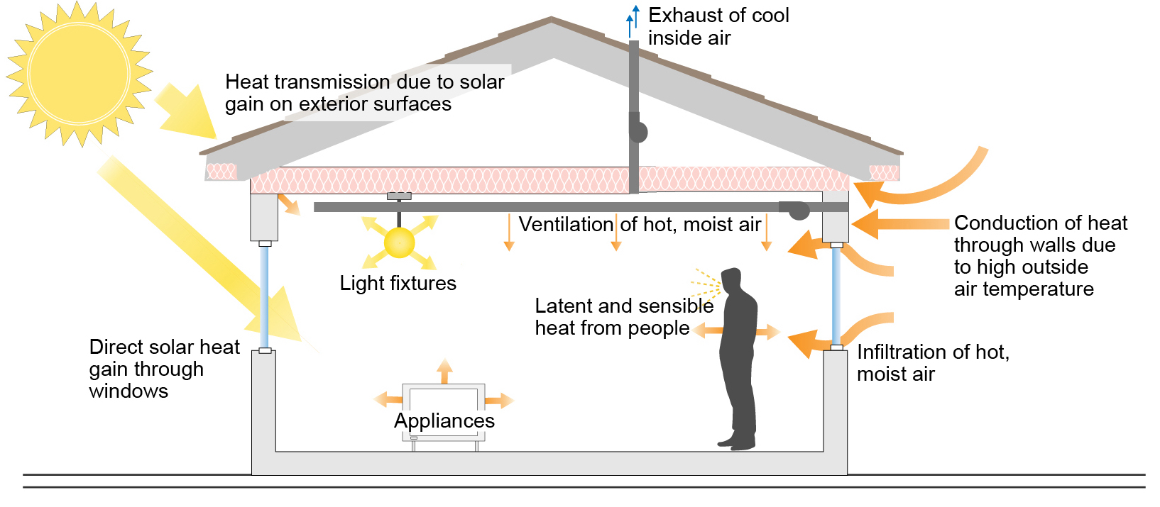
Sources of heat gain in a house include solar gains, infiltration, conduction through walls and roof, occupants, and internal equipment
Image
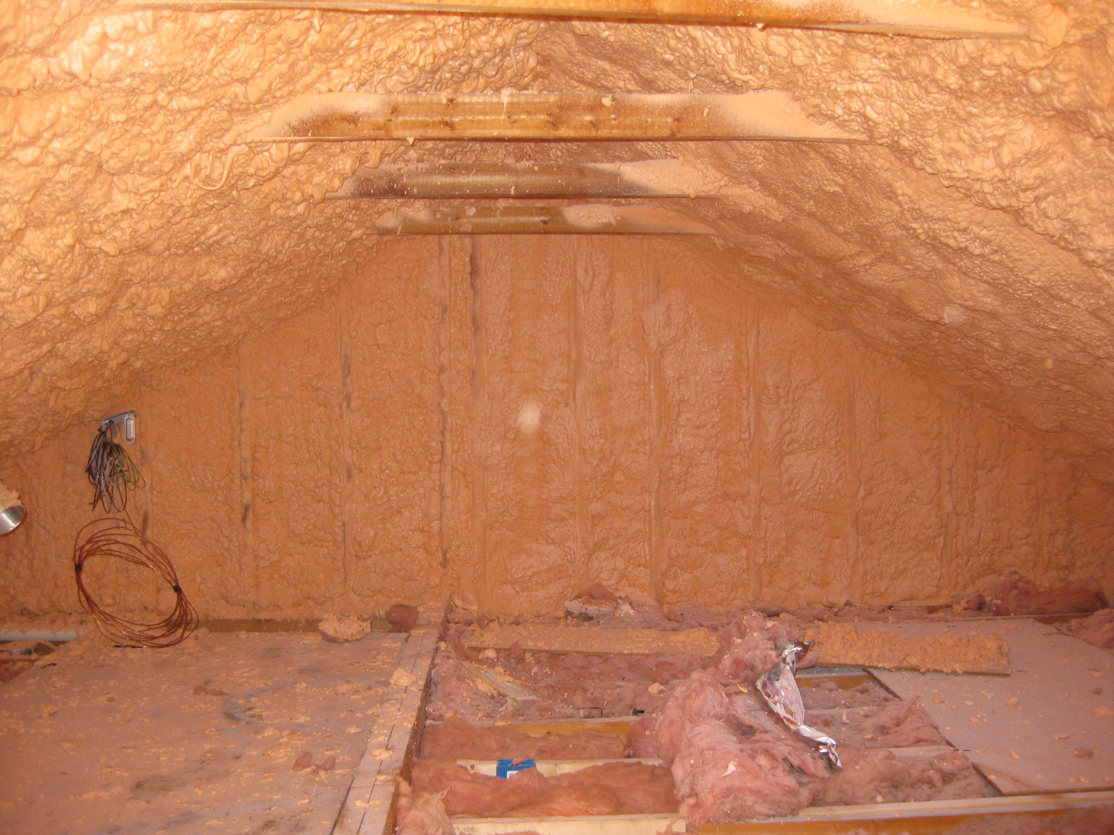
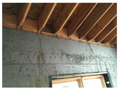
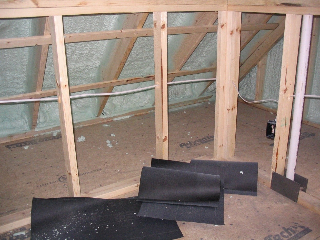
Spray foam insulation was installed on the underside of the roof deck and on gable end attic walls to create an unvented attic
Image
Image
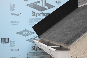
Step 1. Apply roof underlayment over roof deck and up the sidewall over the rigid foam insulation
Image
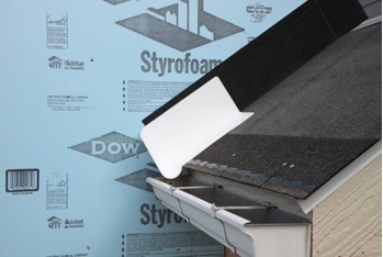
Step 2. Install shingle starter strip then kick-out diverter as first piece of step flashing.
Image
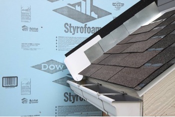
Step 4. Install remaining sidewall flashing, appropriate counter flashing, and shingles
Image
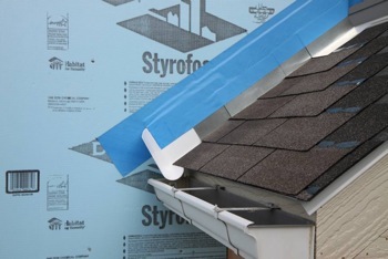
Step 5. Apply self-adhesive flashing over top edge of the wall flashing, diverter, and rigid foam insulation
Image
Image
Image
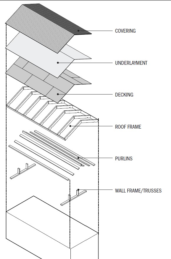
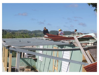
The components of a roof include the rafter framing or trusses, purlins, plywood roof decking, underlayment, and the roof covering.
Image
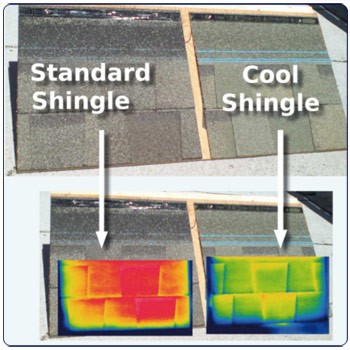
The cool shingles on the right have been coated with a ceramic coating to reflect near-infrared radiation, resulting in a cooler roof as shown by these thermal images (red and yellow are hotter, green and blue are cooler).
Image
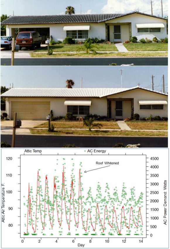
The existing dark tile roof on this home (top photo) was covered with a light -colored coating on day 6 (middle photo), resulting in a significant reduction in attic temperature and cooling energy consumption (bottom)
Image
The geometry of this roof encouraged drifting of snow leading to heavy accumulation between the gables
Image
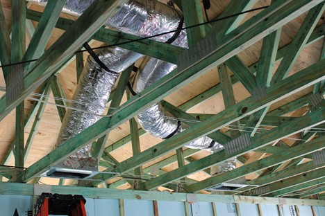
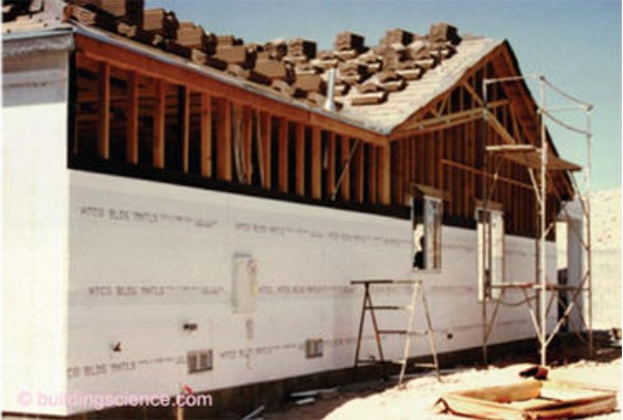
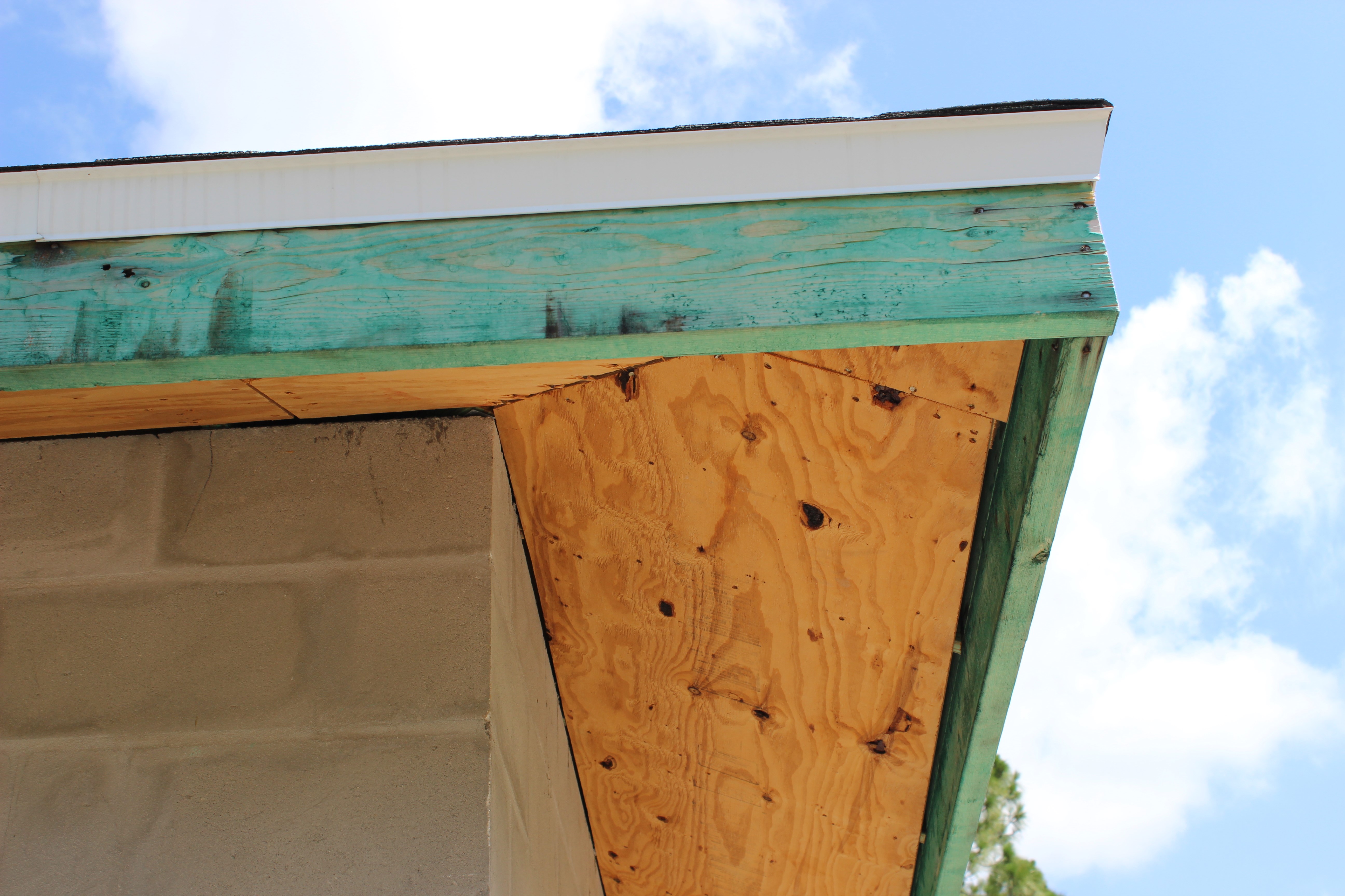
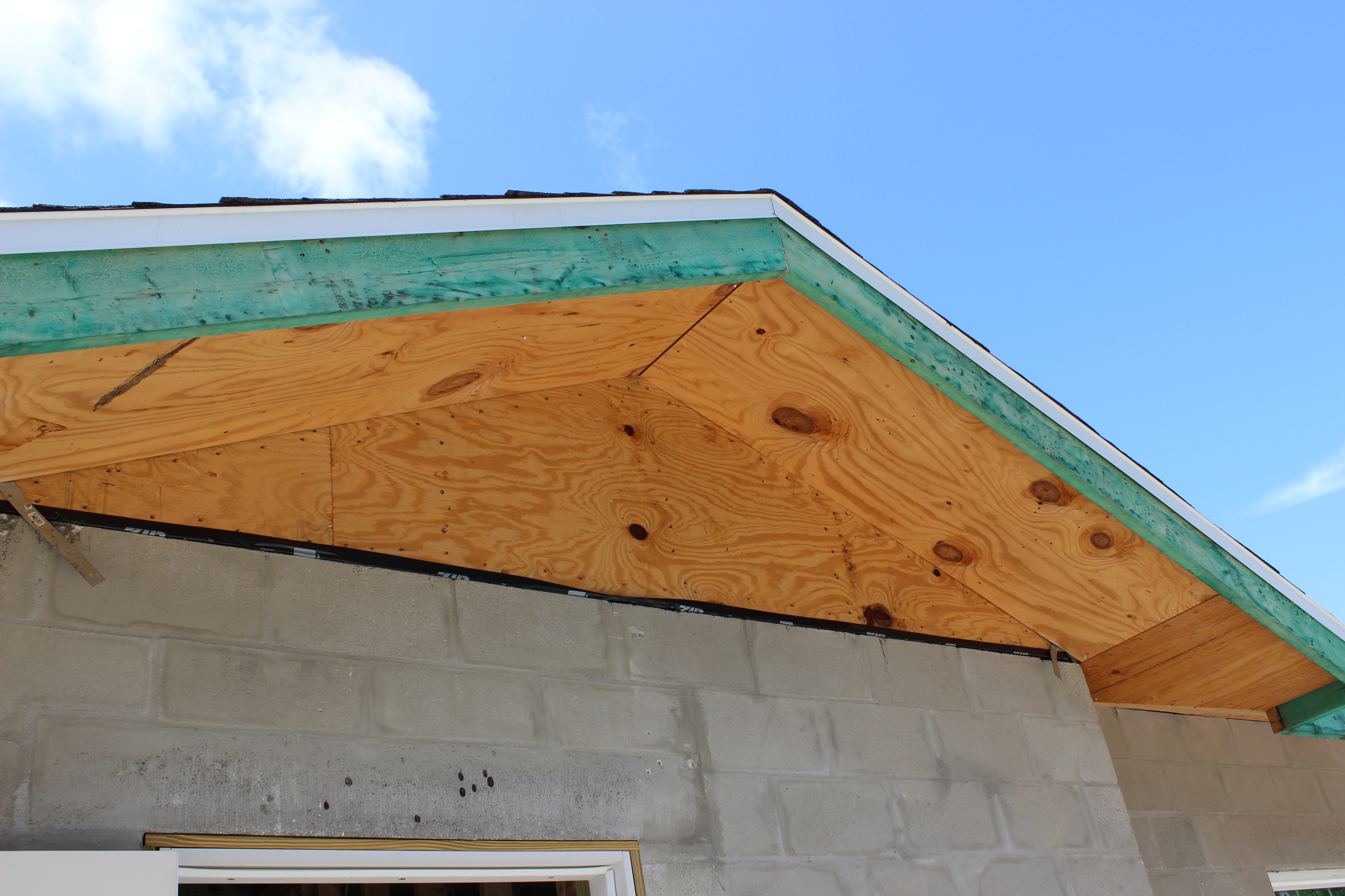
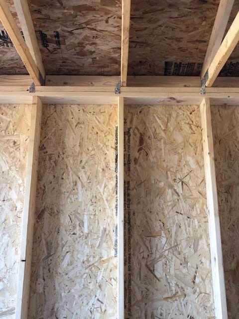
The green framing is lumber that was pressure treated with borate to increase its resistance to termites, mold, and moisture
Image
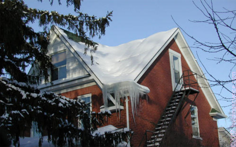
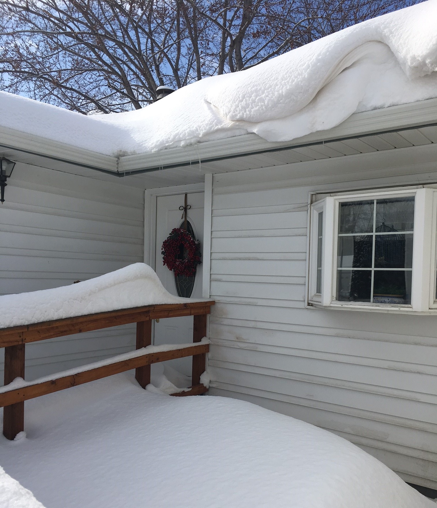
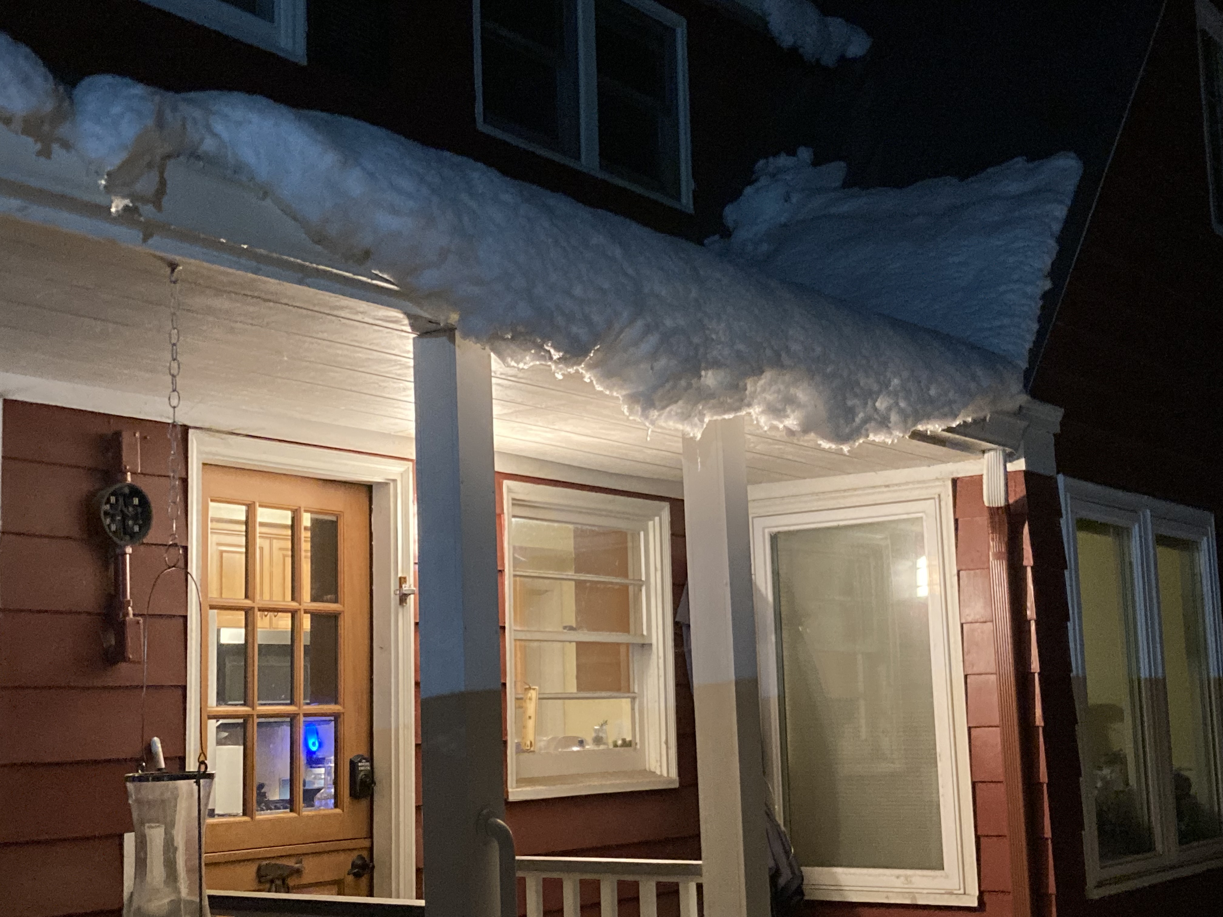
The icicles and the bare spot along the left roof ridge indicate that heat from the second-story room may be heating the underside of the roof deck, melting the snow and likely leading to ice dam formation.
Image
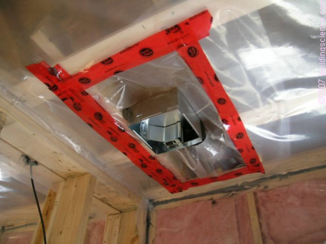
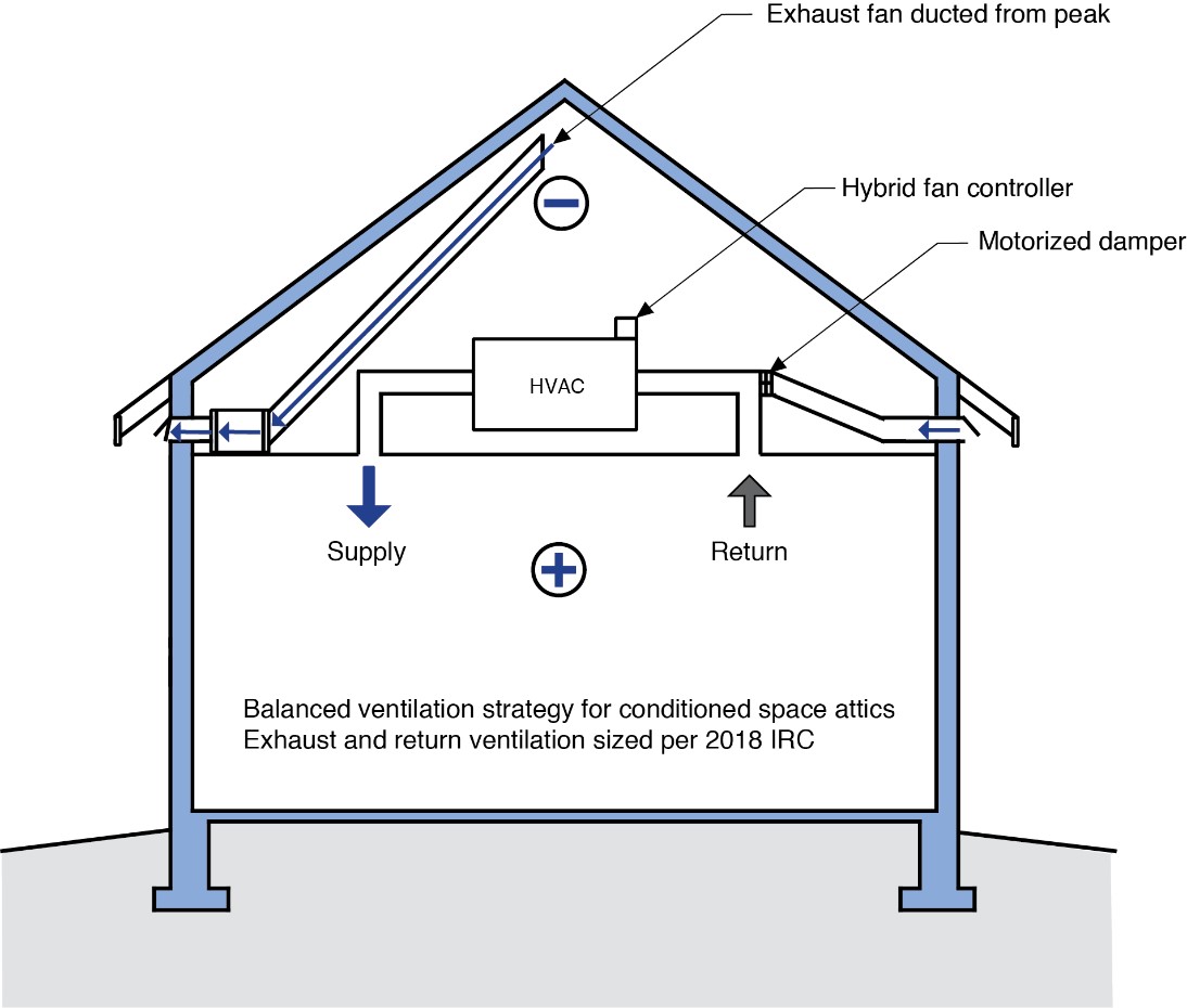
The polyethylene ceiling vapor barrier is sealed to form an air barrier around the exhaust fan in this very cold climate location (≥ CZ 6).
Image
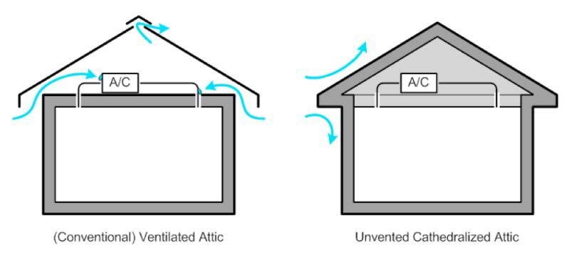
The thermal boundary for a gable roof can be located at either a) the flat ceiling with a vented attic or b) the roof line for an unvented attic
Image
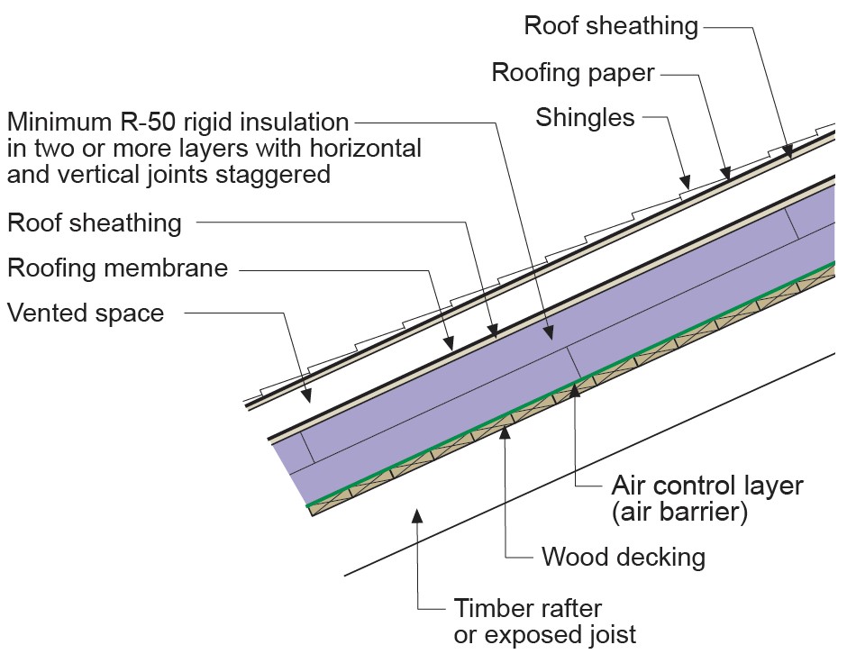
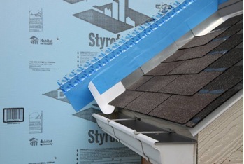
The ventilation space in this vented over-roof keeps the roof cool to prevent ice dams over the unvented attic
Image
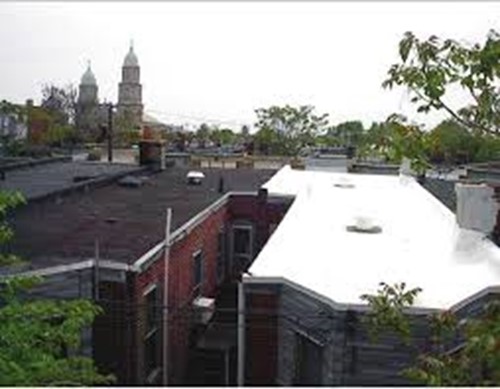
The white TPO membrane roof on the row house on the right performs extremely well at reflecting solar energy and maintaining cool surface temperatures while the black EPDM membrane roof on the left heats up rapidly in the sunlight
Image

These snow guards help to keep snow from sliding off the roof and injuring people below.
Image
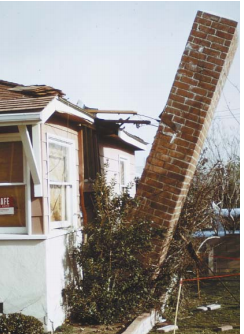
This chimney was not adequately attached to the structure and fell away during an earthquake
Image

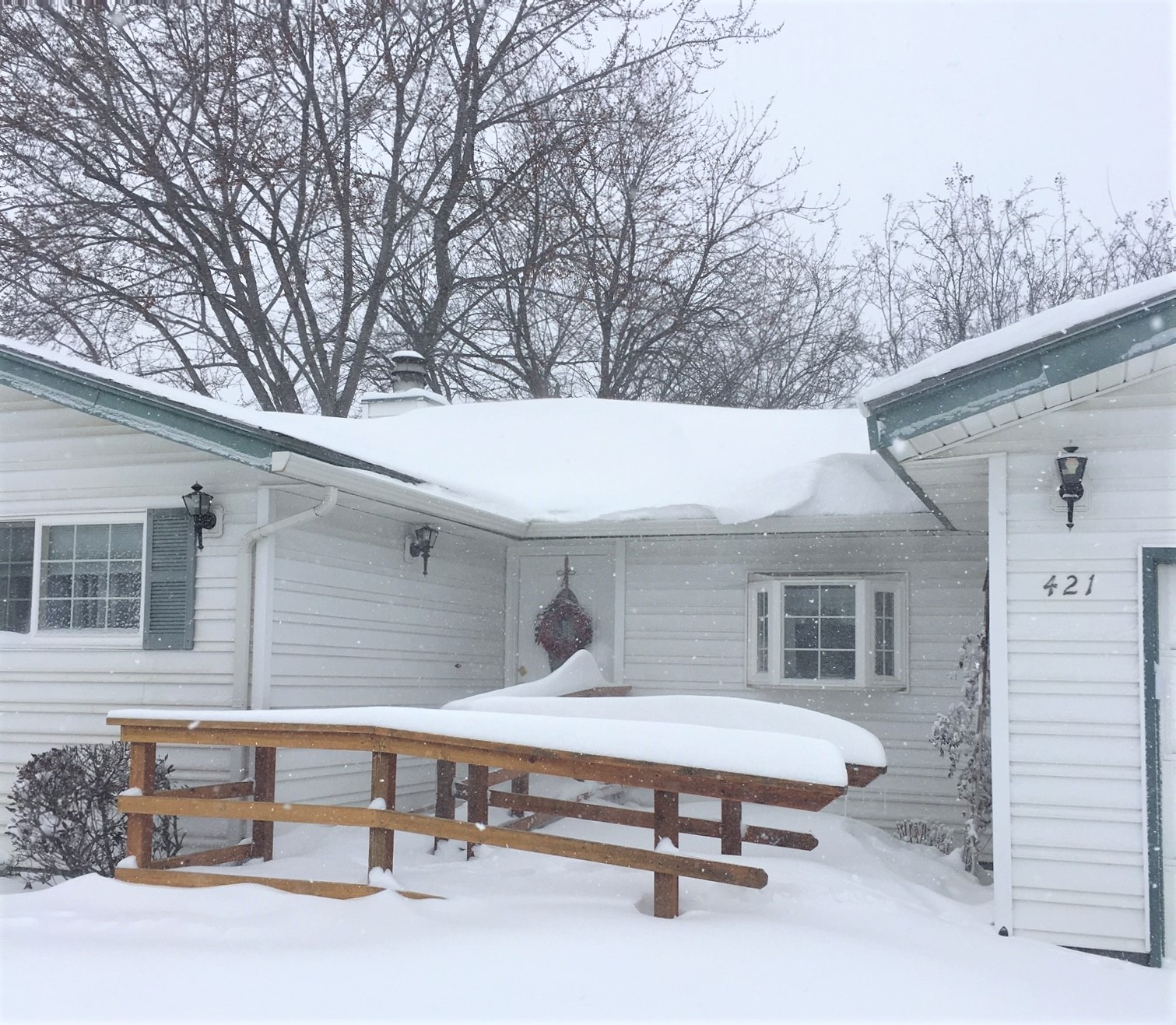
This home has heat loss through the roof, leading to ice dam formation and structural issues during winter months.
Image
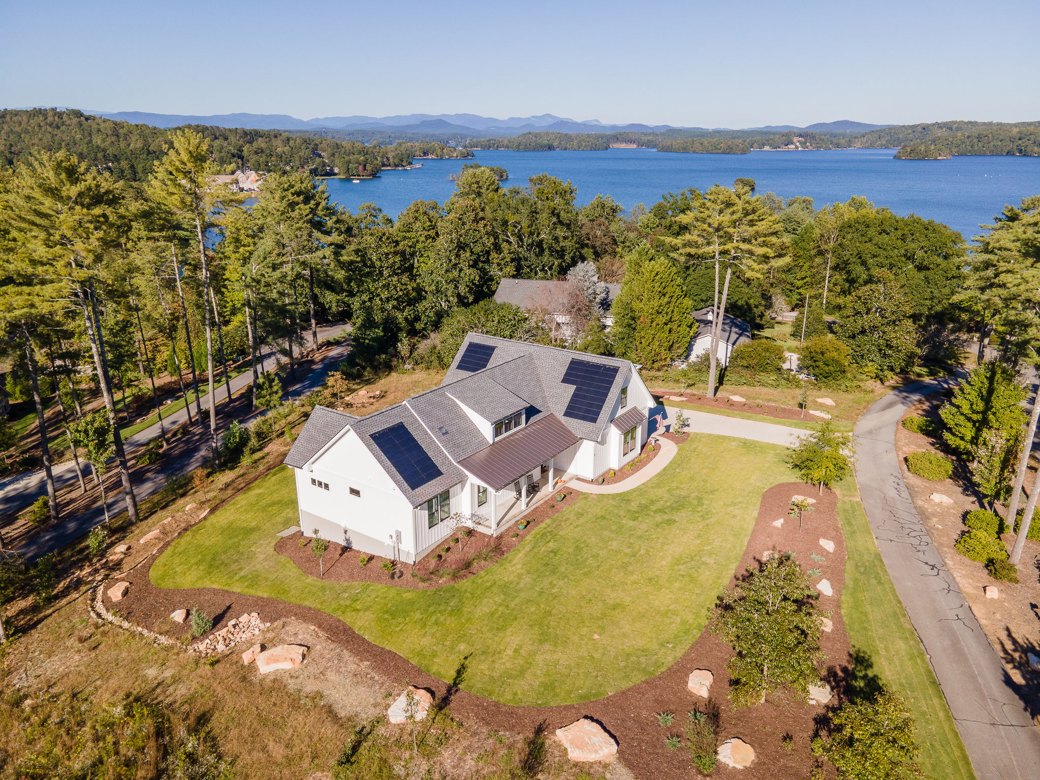
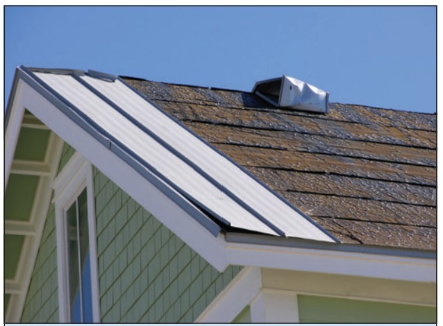
This home was designed with continuous roof vents and few roof penetrations, allowing more room for the solar shingles that integrate with the asphalt shingles installed to meet IBHS Fortified Roof criteria for increased resistance to high winds and rain
Image
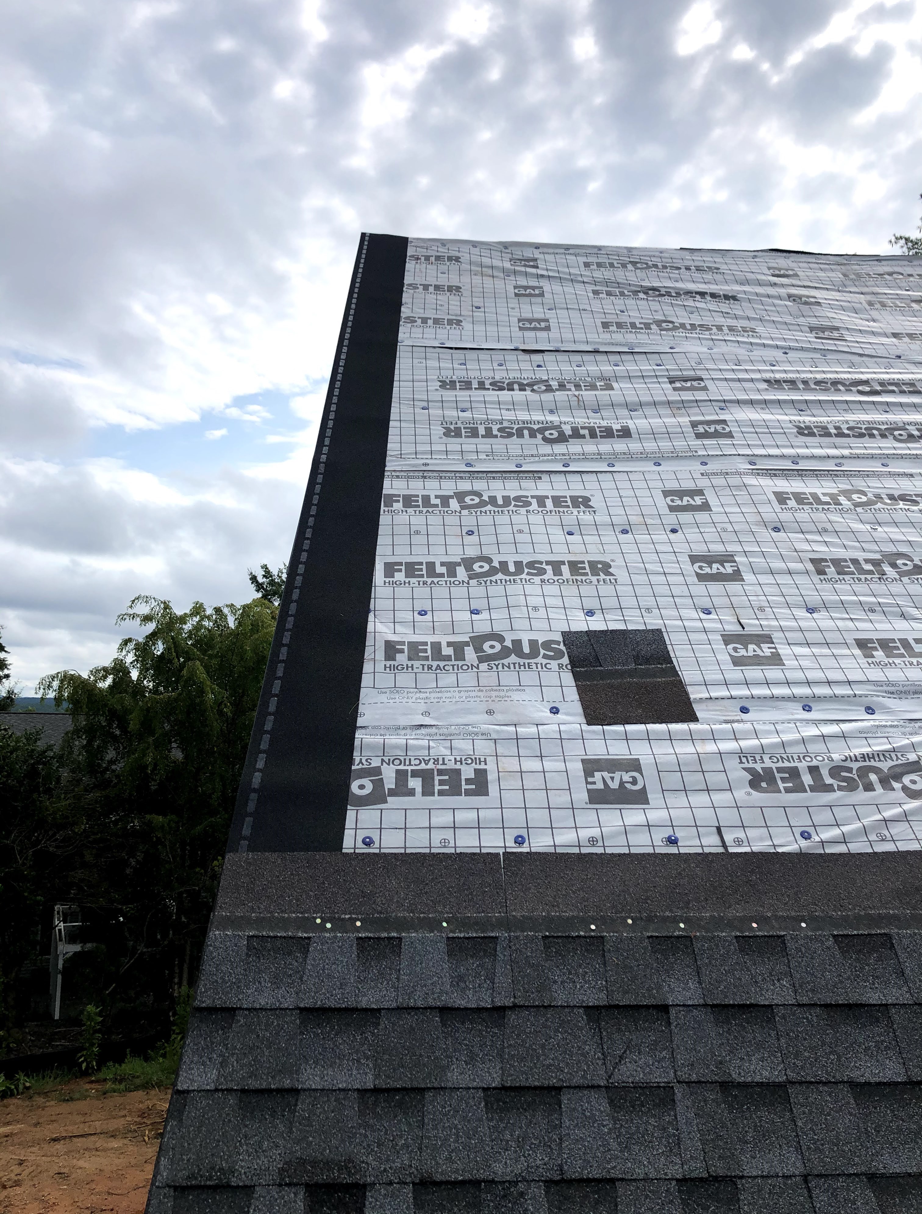
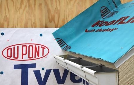
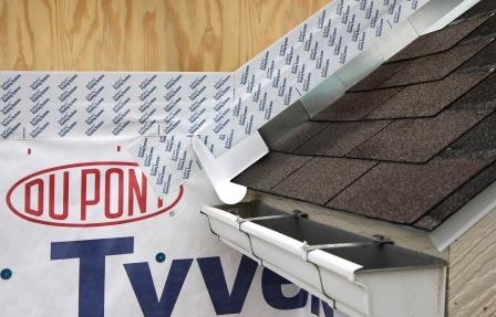
This roof was constructed to meet the IBHS Fortified Roof standard by sealing the decking seams with flashing tape, installing synthetic roof underlayment secured with metal drip edge and nailed every six inches, and using self-adhered starter shingles.
Image

This search for metal roofing products on the CRRC Rated Roof Products Directory highlights the initial and 3-year aged SRI values for each product
Image
Image

Image
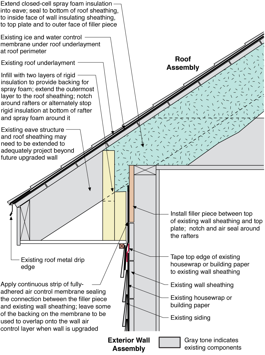
Unvented roof assembly at eave retrofitted with rigid foam, spray foam, and a fully adhered membrane seal at the top of wall-to-roof transition
Image
Using roof and wall materials with a high Solar Reflectance Index (SRI) will reduce heat gains.
Image
Image
Vinyl and aluminum soffit panels can blow away in high winds if not properly connected.
Image
Warm air that leaks into the attic through unsealed light fixtures or other bypasses can melt snow on the roof leading to ice dam formation.
Image
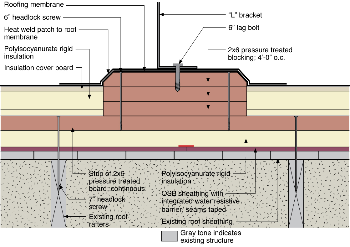
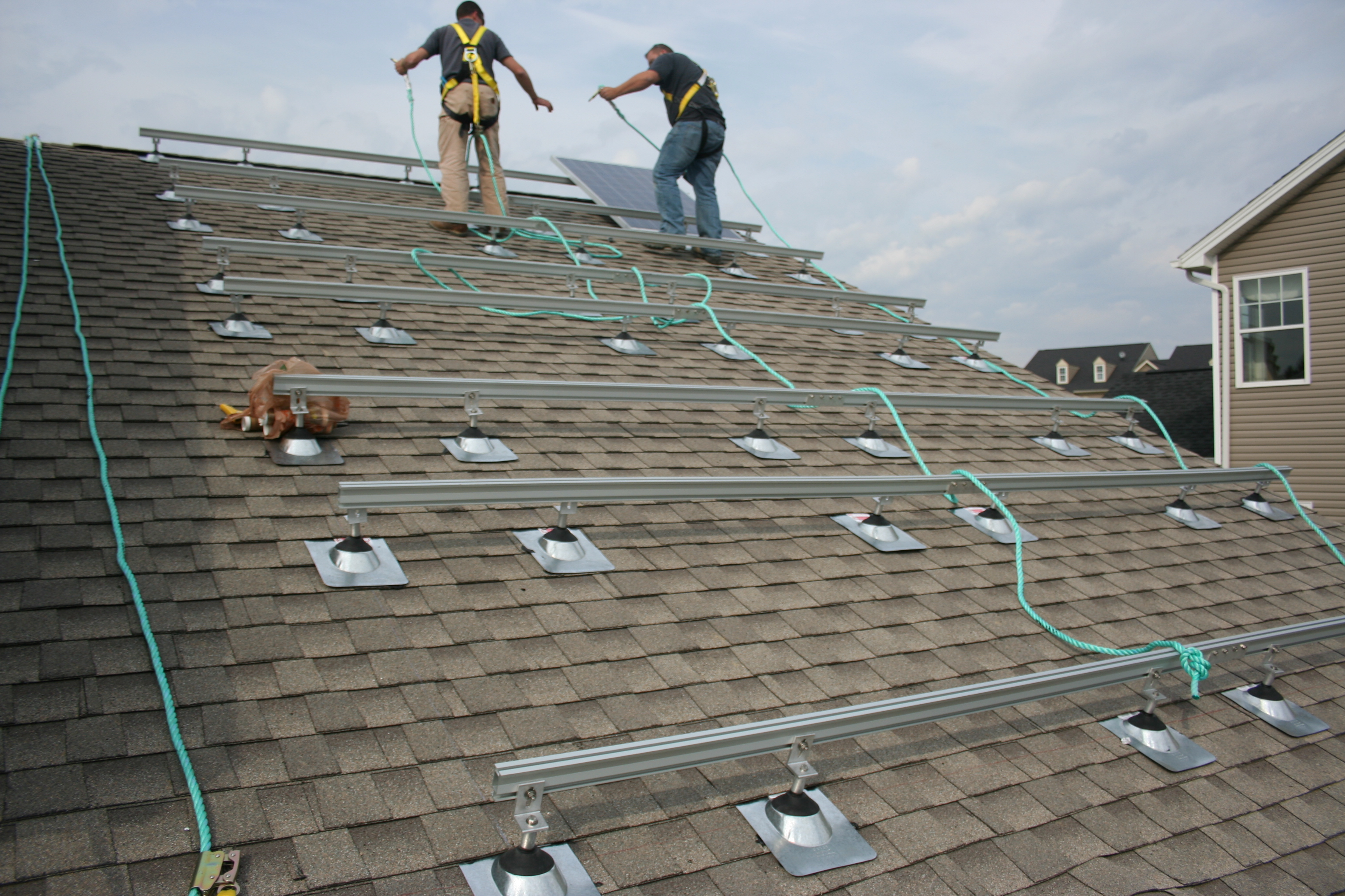
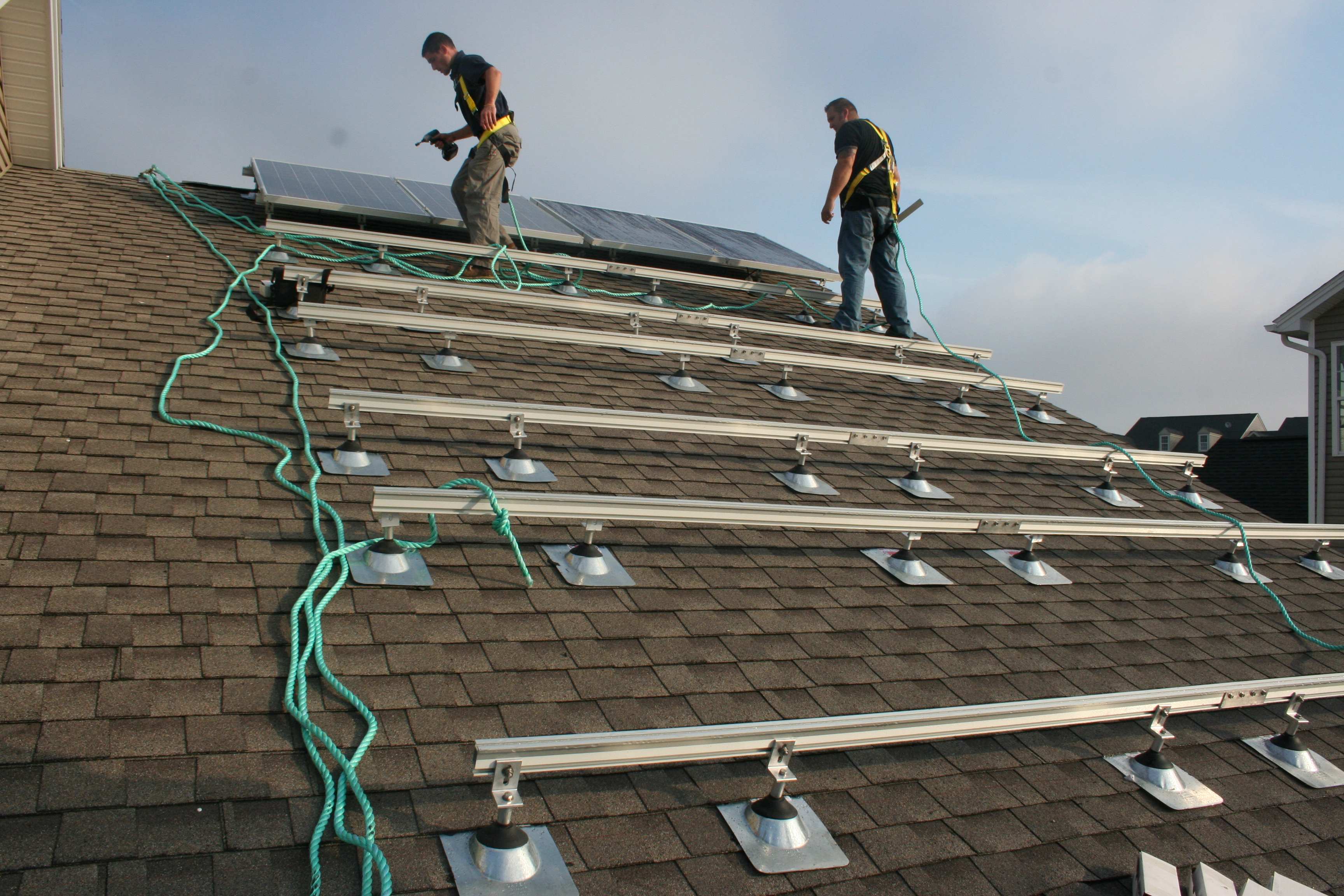
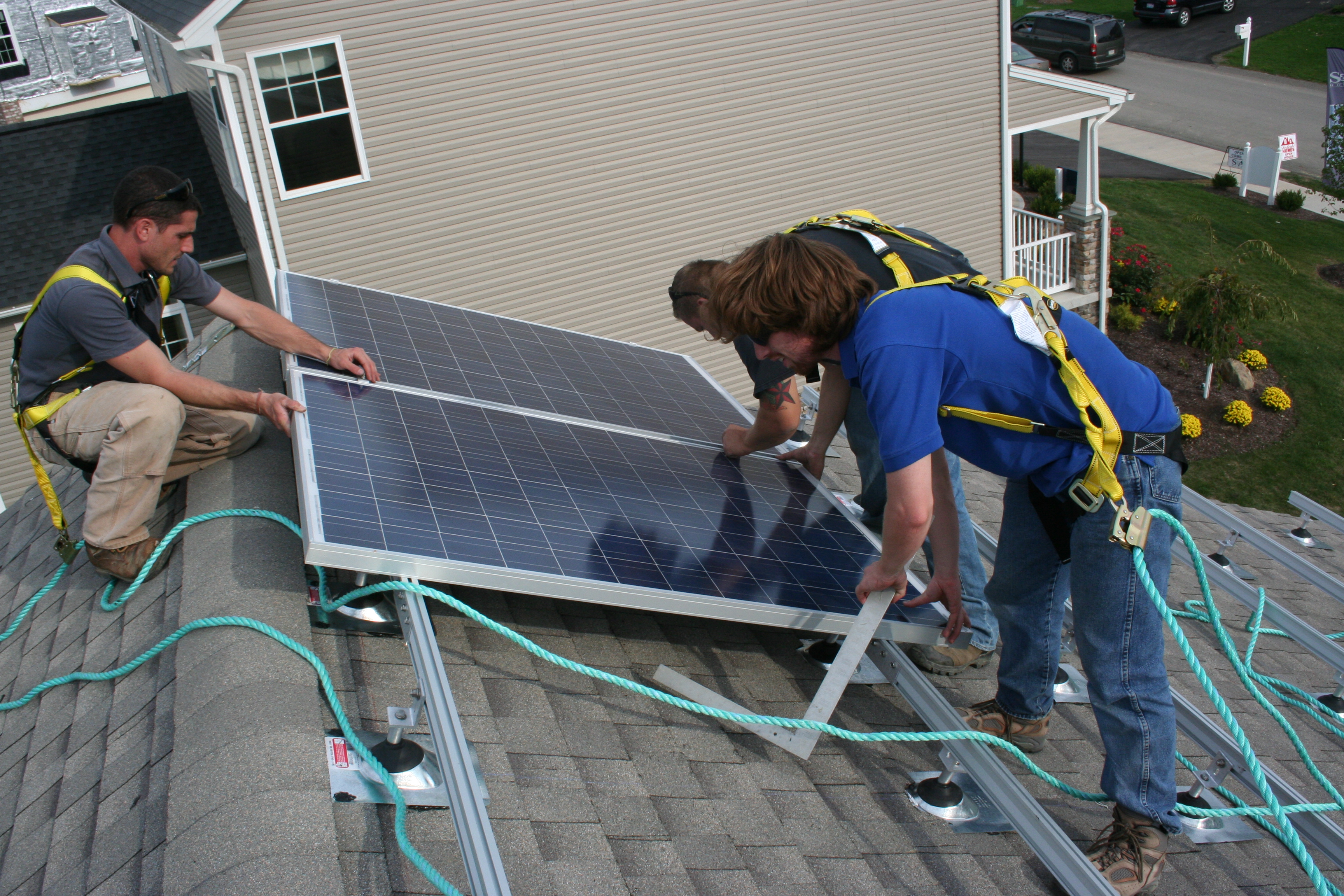
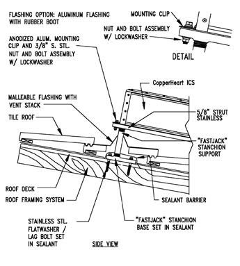
Water management detail for a solar panel rack mounting block installed in rigid foam that was installed over an existing roof
Image
Image
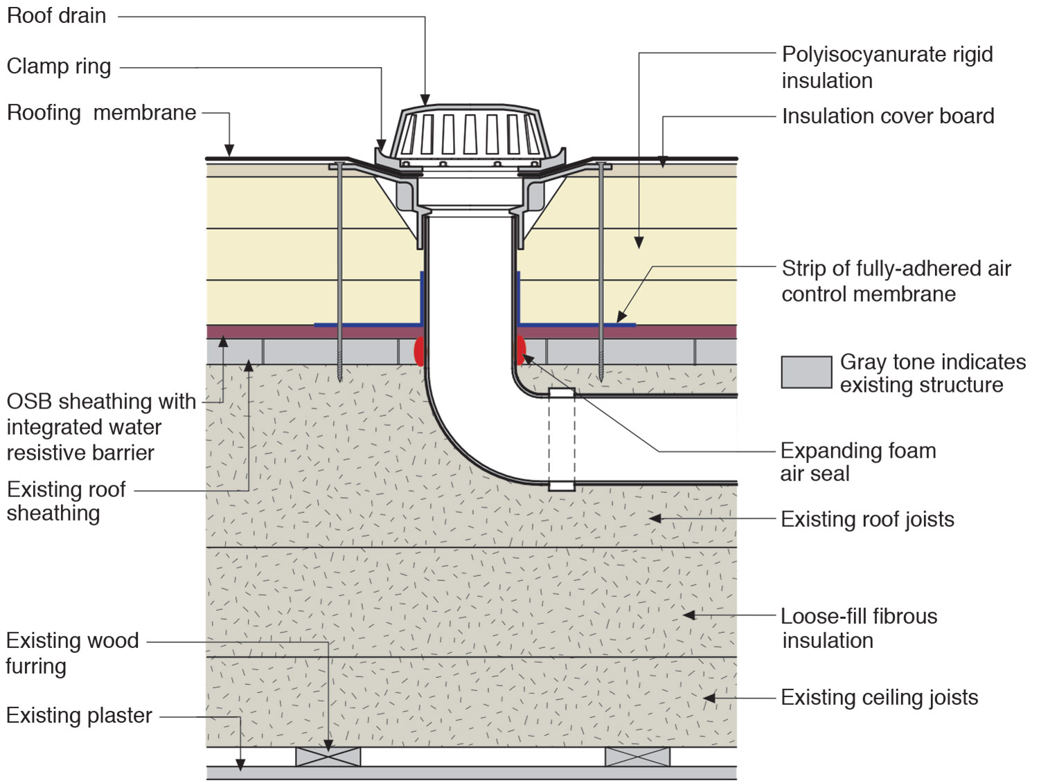
Water management details for a roof drain installed along with rigid foam on a flat roof
Image
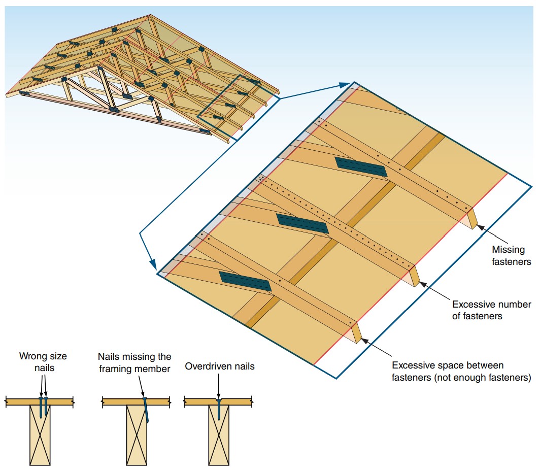
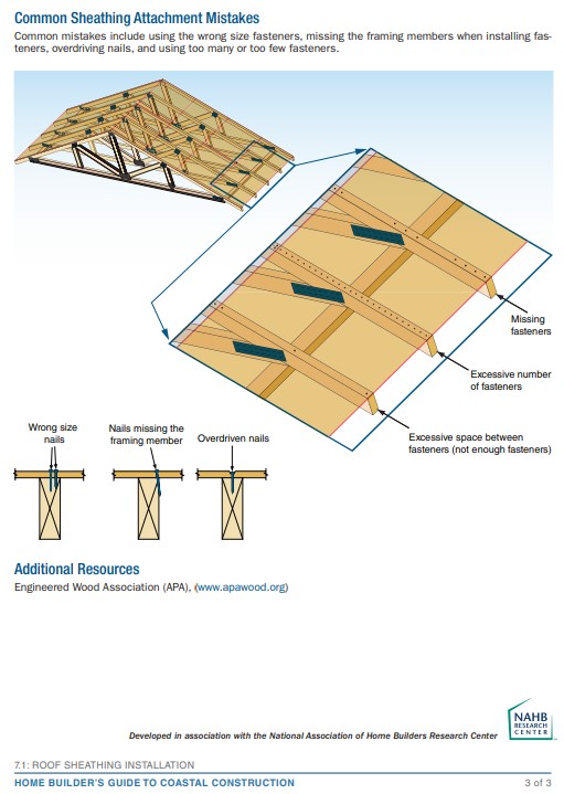
When installing fasteners in roof sheathing, common mistakes include using the wrong size fasteners, missing the framing members, overdriving nails, and using too many or too few fasteners.
Image
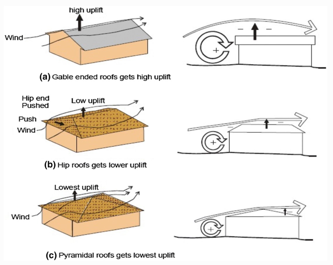
Wind path and uplift force for a gabled roof, a hip roof, and a pyramidal (another variant of a hip) roof design
Image
Image
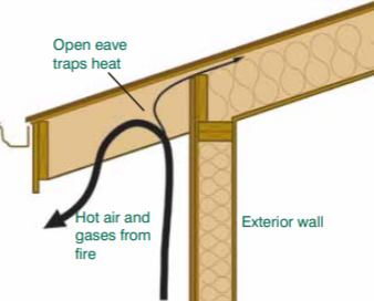
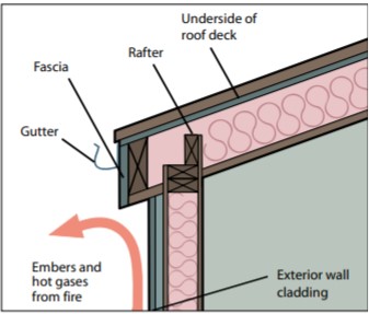
Wrong - An open eave with no soffit covering can trap rising hot air and embers from a wildfire.
Image
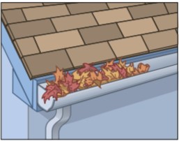
Wrong - Debris in these open gutters can ignite from wind-borne embers and lead to ignition of the roof or fascia board; use leaf screens to keep debris out of gutters in wildfire-prone areas.
Image
Image

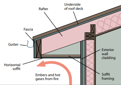
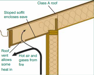
Wrong - If the soffit is applied directly to the rafter eave, it forms a sloping soffit, which creates a pocket that can trap hot air and embers from a wildfire.
Image

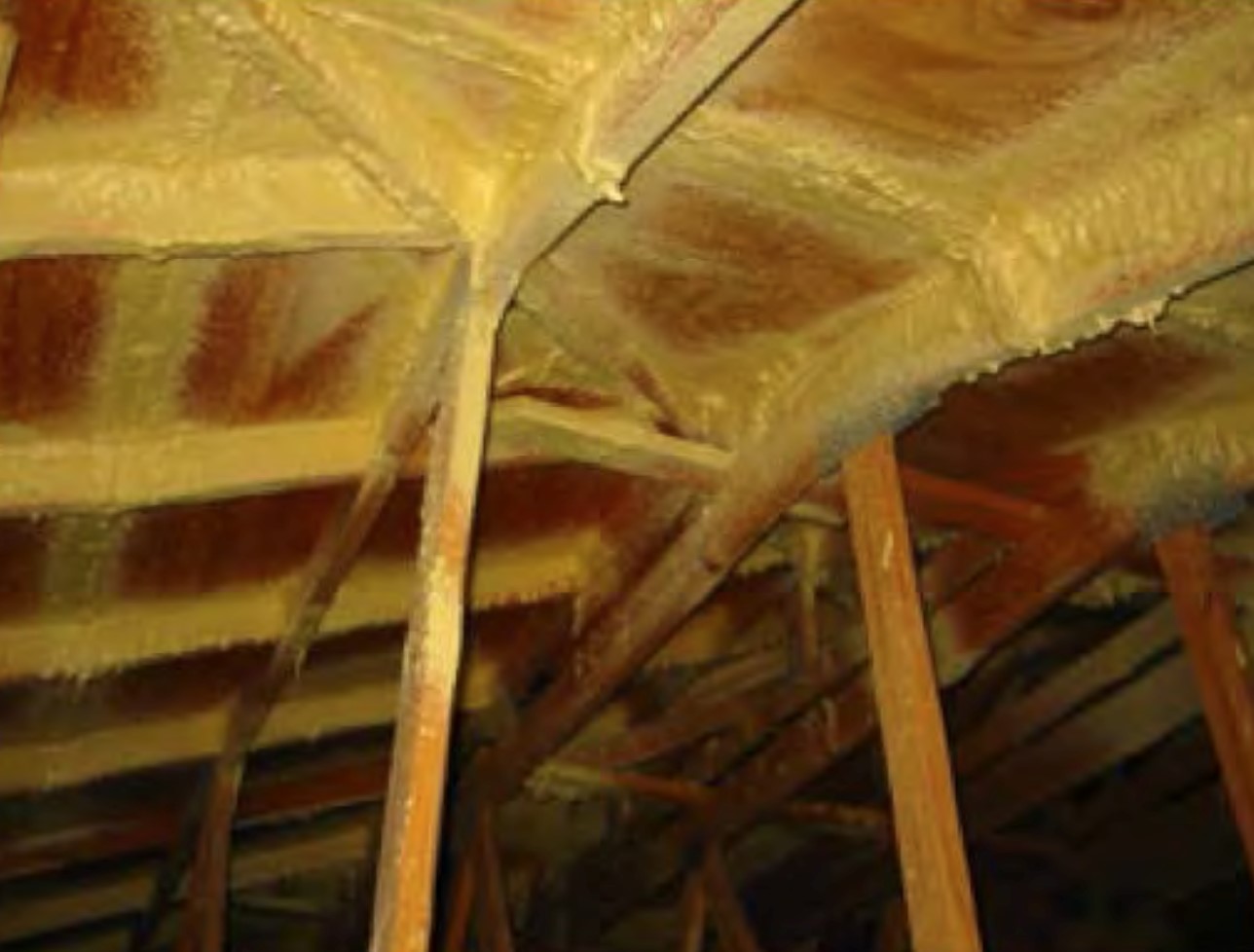
Wrong - Roof deck sheathing nails missed the trusses, potentially weakening the roof in high winds.
Image
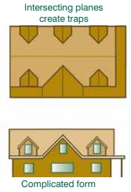
Wrong - Roofs with complex geometries are more susceptible to ignition during a wildfire because they offer more places for burning embers to become lodged.
Image
Wrong - This concrete roof was not adequately attached and reinforced and failed in high winds.
Image
Wrong - This roof failed in high winds due to lack of metal attachments to the framing.
Image
Image
Wrong – An open and/or sloped soffit can trap heat and burning embers as a wildfire approaches, increasing the risk of ignition of the structure.
Image
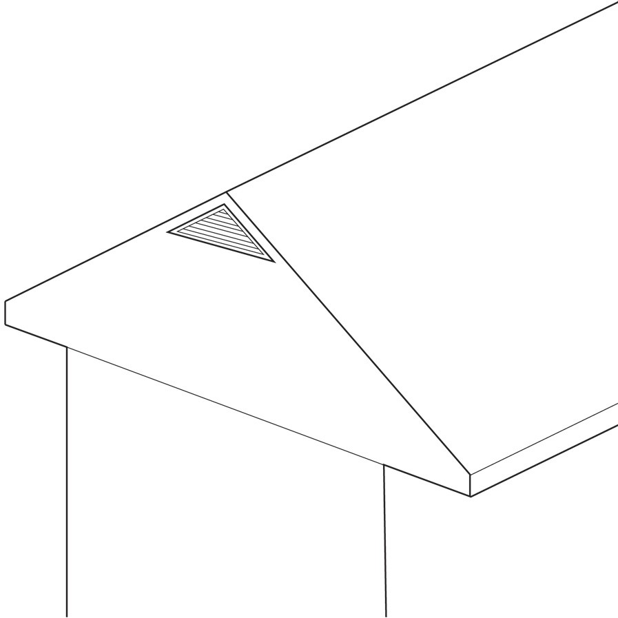
Wrong – Gable end vents can circumvent soffit-to-ridge airflow and allow in wind-driven rain and wildfire embers
Image
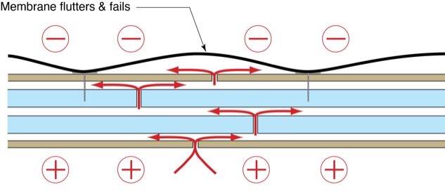
Wrong – If roof membrane is not fully adhered, it can flutter and fail due to negative pressure from wind above and positive pressure from air leakage through roof deck below
Image

Image
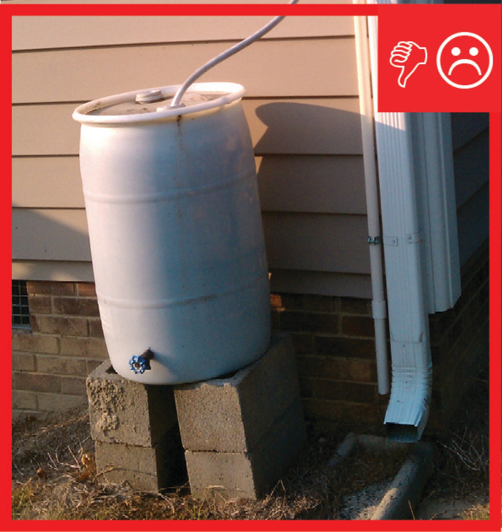
Wrong – Rain barrel installed without an overflow spout that terminates away from foundation
Image
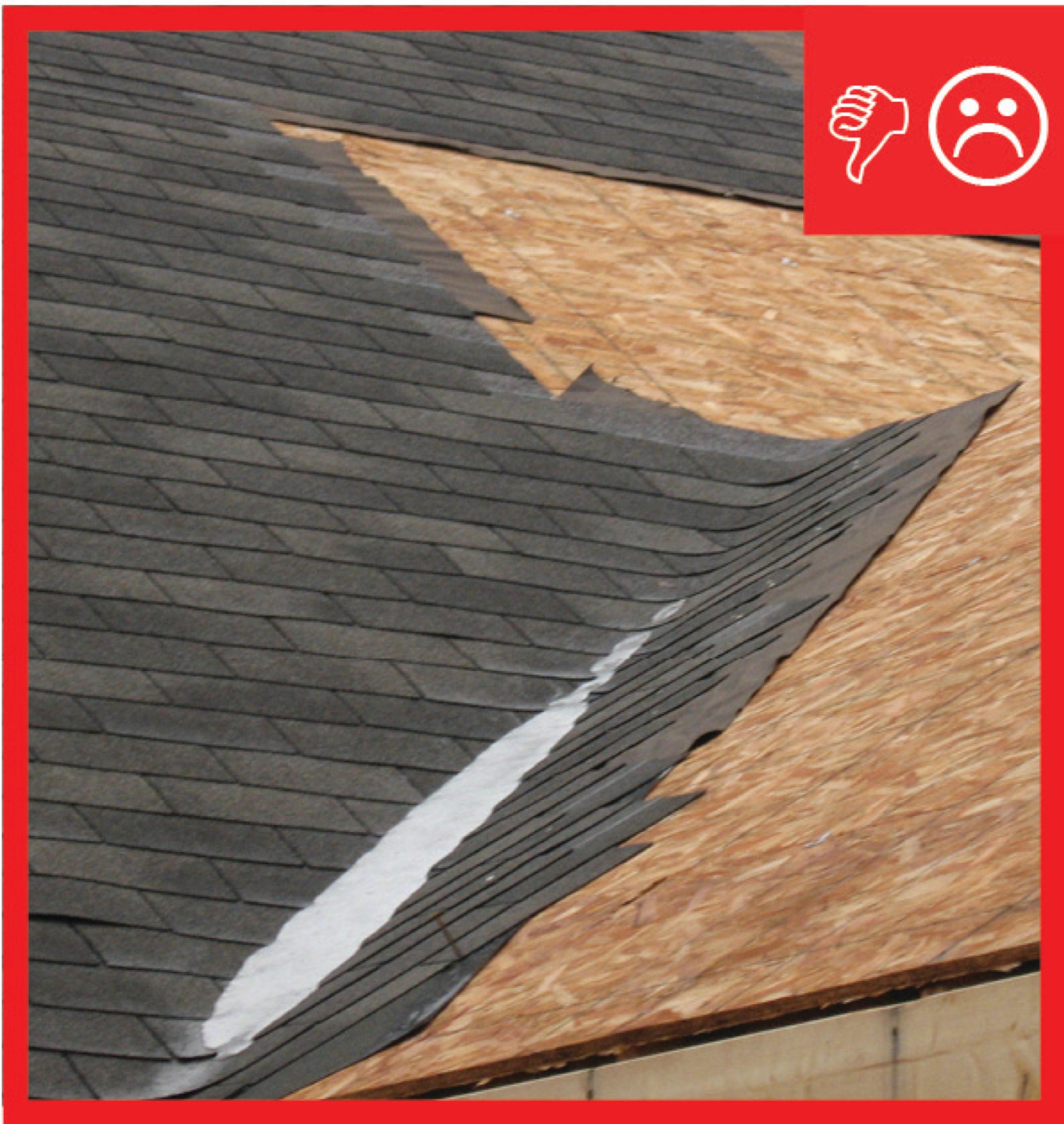
Wrong – Roof underlayment is not fully adhered and roof deck seams are not sealed so roof is susceptible to high-wind events
Image

Wrong – The clips holding these metal roofing panels were set too far from the roof eave (above red line) and the panels lifted in strong winds
Image
Image
Wrong – The metal panels covering this roof used snaplocks and concealed fasteners that gave way in high winds.
Image
Image
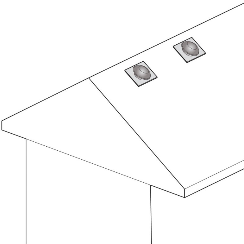
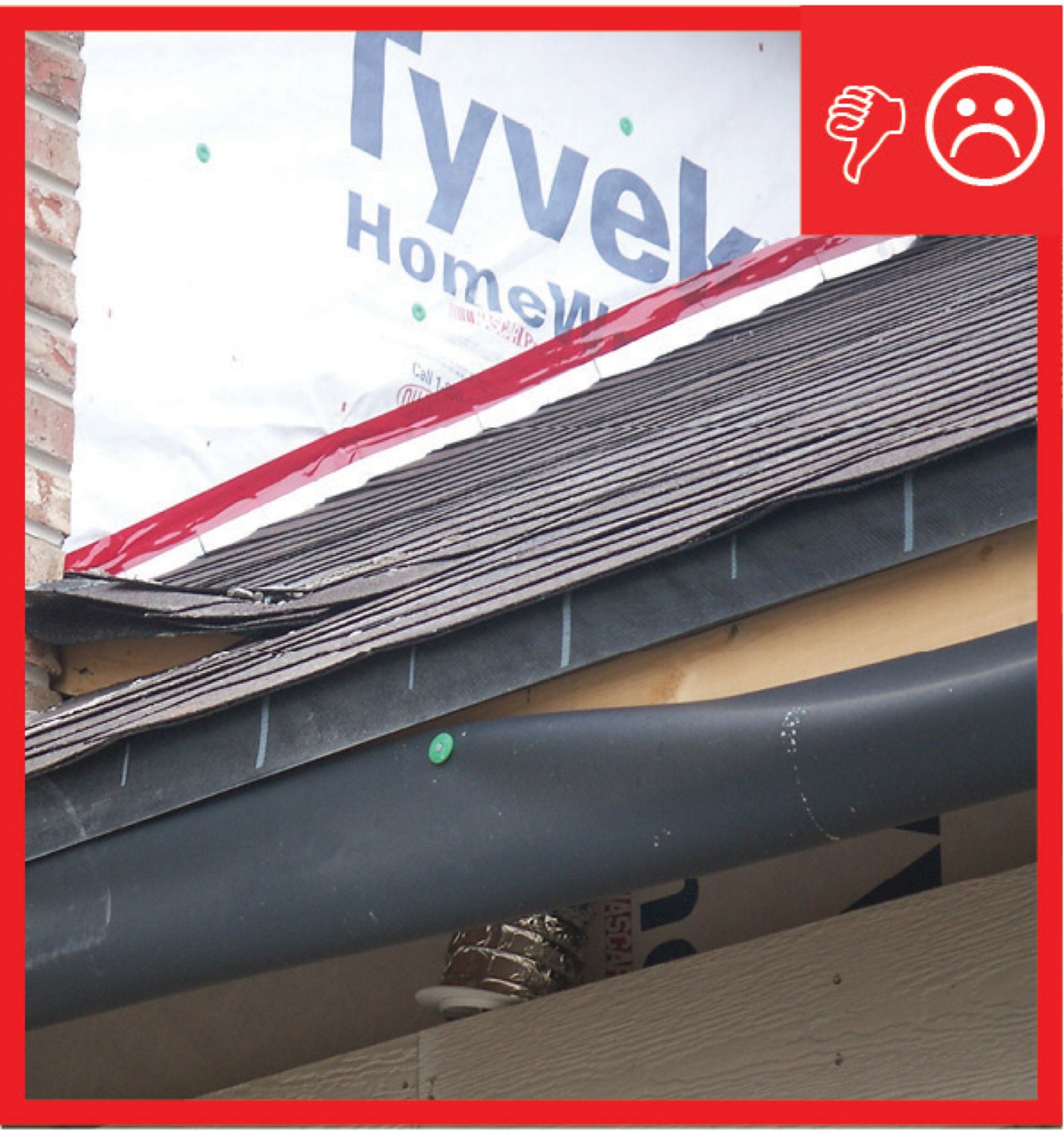
Wrong – The off-ridge roof vent on the right was poorly anchored and pulled off in high winds allowing water into the home.
Image
Wrong – The open overhang with exposed timbers and unscreened vent holes make this roof more susceptible to ignition.
Image
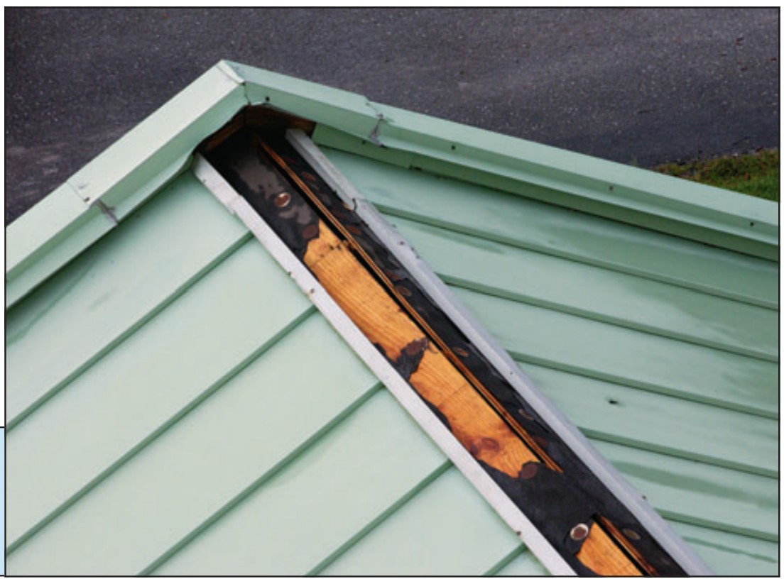
Wrong – The ridge flashing fasteners were placed too far apart and came loose in high winds.
Image
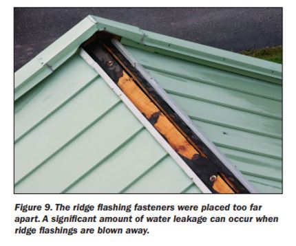
Wrong – The ridge flashing fasteners were placed too far apart and did not adequately hold the flashing in place
Image
Image
Wrong – the water-resistant barrier is layered underneath the step flashing, which could allow water to get behind the step flashing and into the wall.
Image
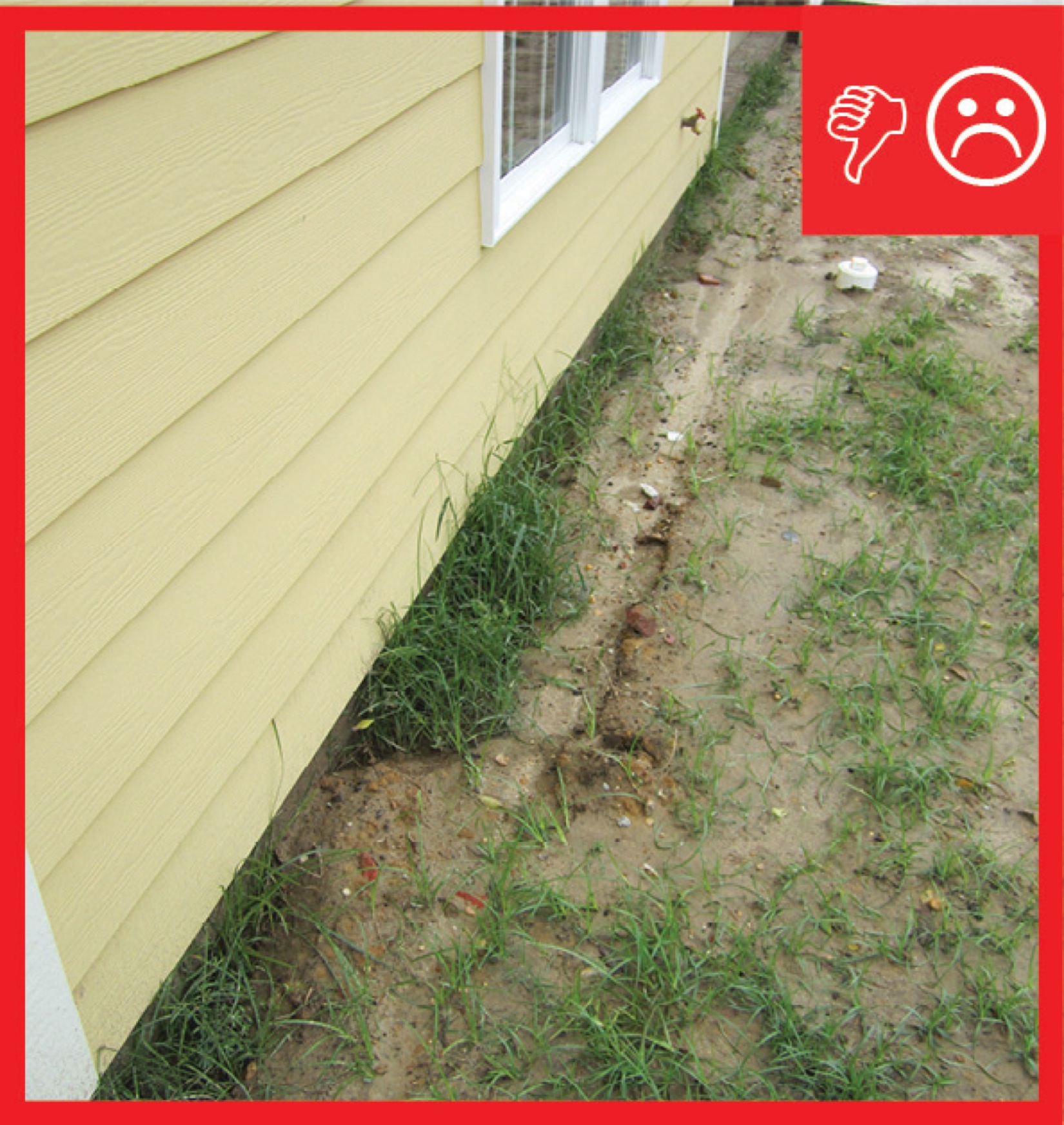
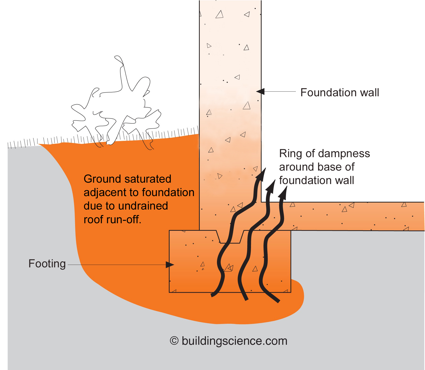
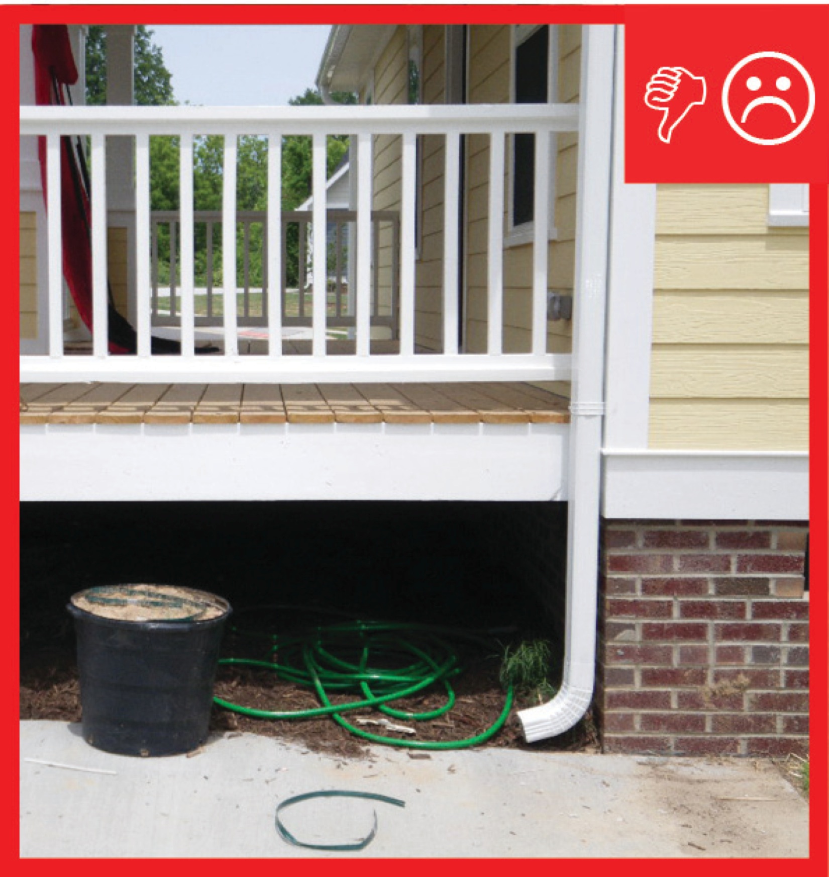
Wrong – There are no gutters installed and there is not a proper gravel bed located at the foundation
Image
Wrong – There is not a self-sealing bituminous membrane installed at the valley of the roof
Image
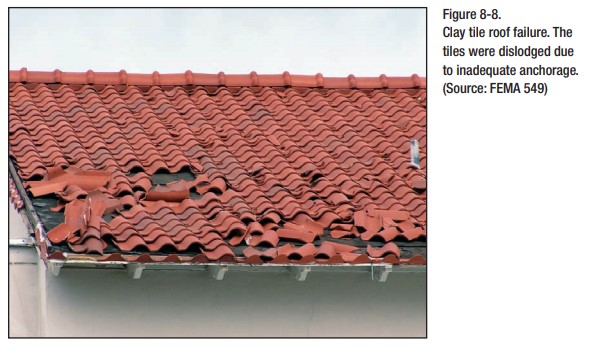
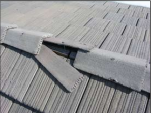
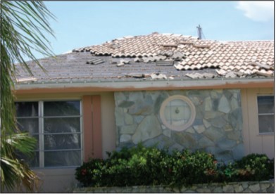
Wrong – These clay roof tiles were dislodged by high winds due to inadequate anchorage.
Image
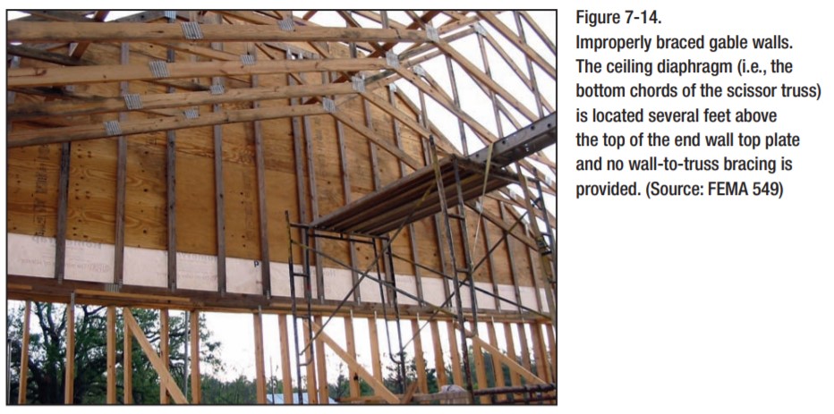
Wrong – This house under construction is lacking wall to truss bracing and the bottom chord of the scissor trusses is several feet above the top of the end wall top plate
Image
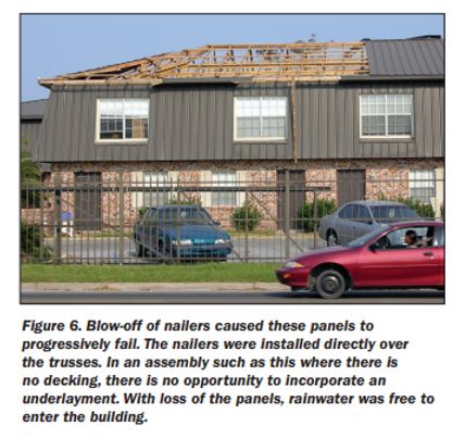
Wrong – This roof has no sheathing, when the metal panels blew off there was no secondary protection