2021 IECC Climate Zone 3C Building Assembly: SIP Roof, SIP Wall, Stem Wall, Slab on Grade
2021 IECC Climate Zone 3C: SIP Roof, SIP Wall, Stem Wall, Slab on Grade
Notes
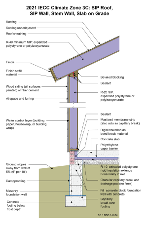
Drawing 3C.1: IECC CZ 3C: SIP Roof, SIP Wall, Stem Wall, Slab on Grade
- This wall and roof assembly is constructed using structural insulated panels (SIPs).
- It is important to seal the interior joints of the SIP roof panels to provide air control layer continuity.
- Many code officials do not count SIPs as continuous insulation when applying Table R402.1.3 of the 2021 IECC. Hence, the R-values shown in the drawing are based on the cavity insulation requirements of this table. However, SIPs walls and roofs typically have much lower framing factors than typical framed walls, resulting in less thermal bridging. For these reasons, it may be most appropriate to use the U-factor table (Table R402.1.2) or the UA alternative (Section R402.1.5) for code compliance rather than using prescriptive R-values. U-factor should account for the thermal bridging of the assembly.
- Note that this assembly does not have an attic (vented or unvented). If the assembly did have an attic space, Section R402.2.1 of the 2021 IECC may apply, depending on the interpretation of the local code official. If so, R-38 could be used over the attic rather than R-49 as long as the R-38 insulation extended over the full width of the exterior wall top plate.
- A low-permeance roofing underlayment (less than 1 perm) is recommended for this roof type in this climate to reduce water diffusion through the underlayment to the sheathing.
- A drainage plane should be created behind the siding by using a draining housewrap or furring strips. Furring strips only need to create a gap of at least 1/4", so a material such as sill gasket strips installed vertically can be used in place of typical wood.
- The function of the masticed membrane strip under the sill plate is to control entry of termites. It must be fully adhered. Another termite control approach is to use a strip of stainless-steel mesh embedded in mastic.
- Per 2021 IECC, the under-slab insulation only needs to extend inward 2 feet for Climate Zone 3. However, extending 4 feet may prevent potential comfort issues.
- Portions of the CMU wall may need to be filled solid to meet structural requirements or to accommodate anchor bolts for a sill plate.
- The entire below-grade portions of the stem wall should be coated with dampproofing to control capillary uptake.
2021 IECC Window Detail: Framed Wall with Plywood or OSB Sheathing, a WRB, and Siding (Wood, Fiber Cement, Aluminum or Vinyl, or Stucco)
Notes
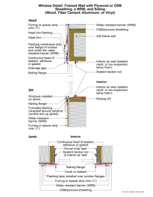
Window Detail 4 - Framed Wall with Plywood or OSB Sheathing, a WRB, and Siding (Wood, Fiber Cement, Aluminum or Vinyl, or Stucco)
- Note: Always follow the window manufacturer’s installation guidance. Not following manufacturer guidance may void the warranty.
- This is a “drained wall”. Drainage occurs between the siding and the water control layer or water resistant barrier (WRB) in the gap created by furring which is installed vertically over the water control layer (WRB) at stud locations. In the case of a stucco wall, the drainage plane is a drainage mat rather than furring gaps.
- The window openings are drained to the water control layer (WRB).
- The rough opening at the window sill is sloped and flashed with a formable flashing.
- The upper portion of the head trim flashing goes under the furring and is taped directly to the WRB with flashing tape. The furring is “cut through” by the head trim flashing, so that the furring below the flashing (behind the head trim) is separate from the furring above the flashing (behind the siding). During construction, the head trim is installed first on short strips of furring. It is flashed directly to the WRB as described above. The rest of the furring is installed with the siding. In the case of a stucco wall, the drainage mat would be treated in similar fashion to furring: the head trim flashing would go under the drainage mat and be taped directly to the WRB with flashing tape.
- Note the gap between the head trim and the top of the window assembly frame. This gap allows water to drain and allows the bottom of the trim to dry out more easily. If installed without this gap, capillary action can draw water into the tight space between the head trim and the window assembly frame. Note also the gap between the siding and the head trim flashing, which serves the same purposes.
- Consider installing rigid head flashing (rigid head flashing is not shown in the schematic). Rigid head flashing is similar to the head trim flashing shown in the schematic, but it goes over the top of the window frame instead of over the head trim. This is required by some manufacturers. It should be installed against the head nailing flange and over the top of the window frame. The vertical and horizontal portion of the flashing should be sealed directly to the window frame and flange with sealant. The red flashing membrane strip shown overlapping the head nailing flange in the schematic would now overlap the rigid head flashing. Use rigid head flashing with a drip edge to guide water away from the window assembly.
- Backer rod for the interior air sealant should be installed after the window is installed, leveled, and shimmed. Use the correct size backer rod.

