
Scope

All seams between structural insulated panels (SIPs) foamed and/or taped per manufacturer's instructions

Seal all seams between Structural Insulated Panels (SIPs) with foam and/or tape per manufacturer’s instructions.

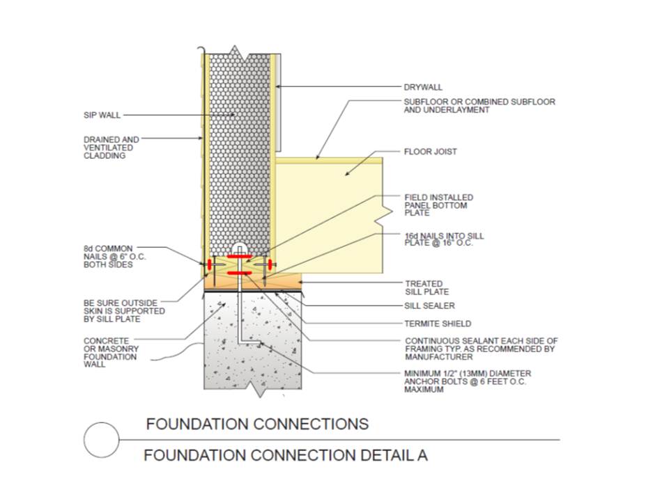
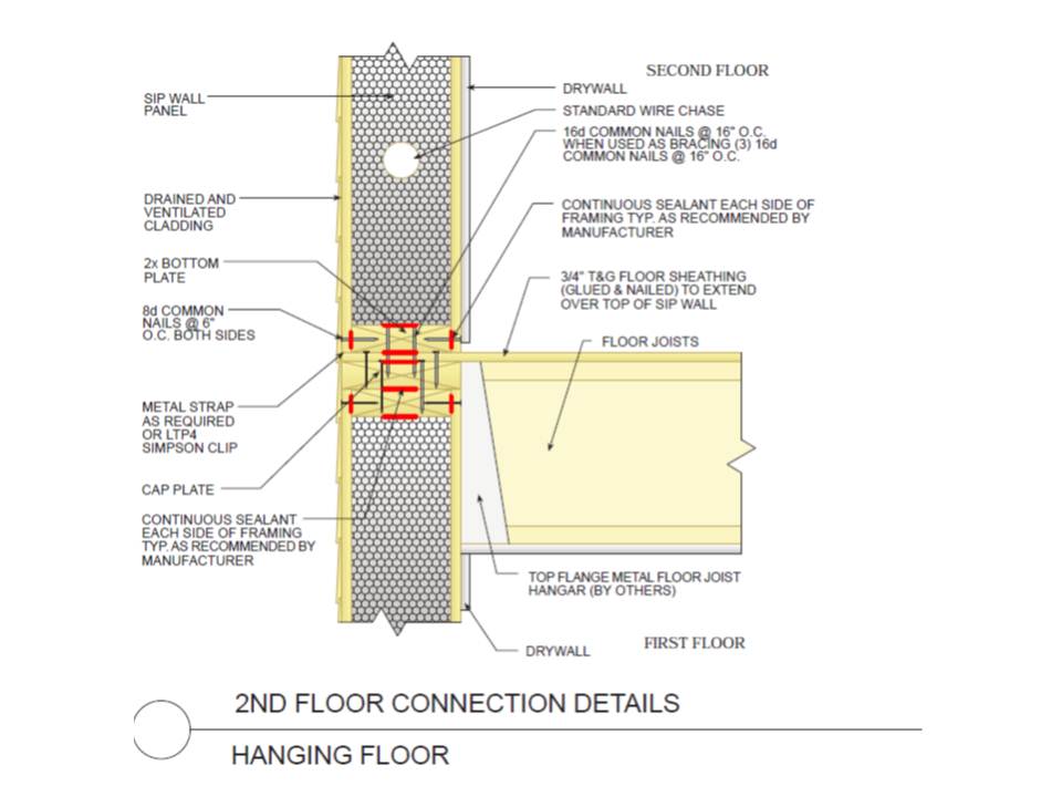
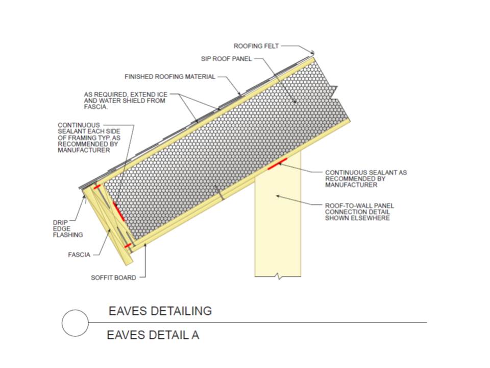
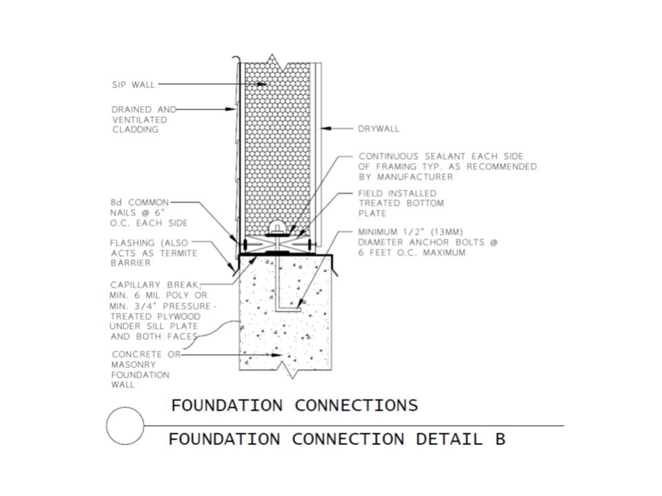
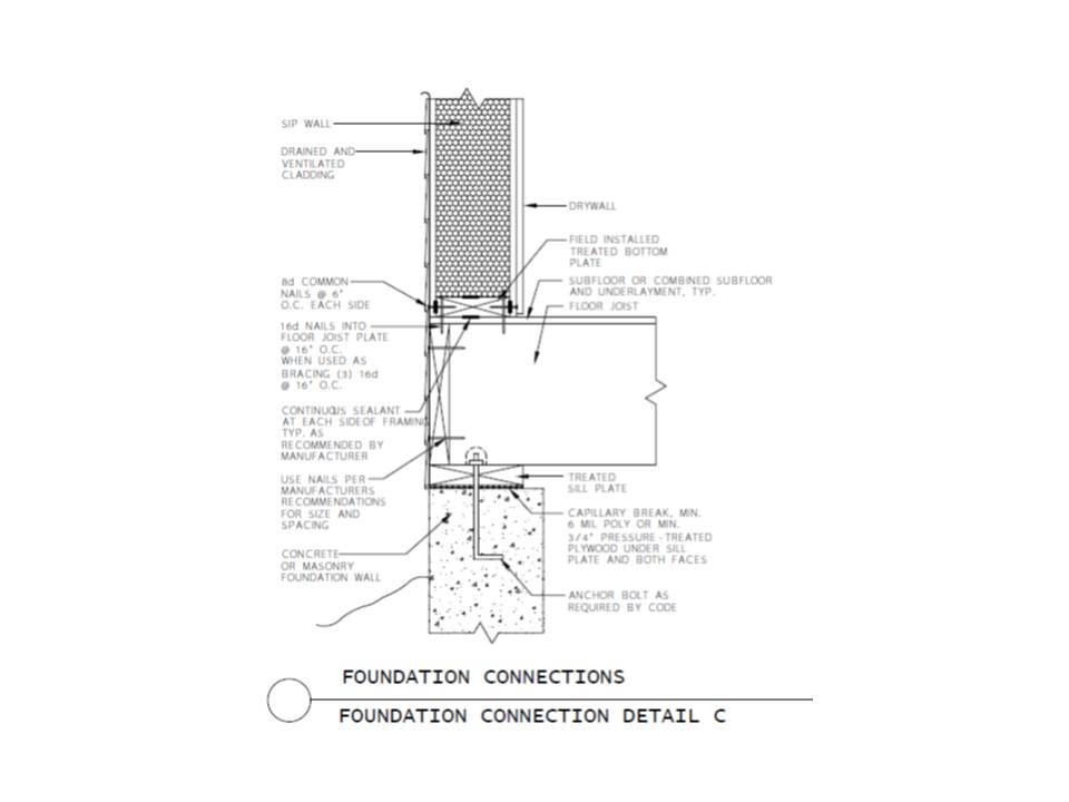
  • Apply manufacturer-approved sealant inside the joints of all panels and at the sub-floor or foundation connections.
  • When applying tape to walls, center it on the joints and provide overlap of tape to meet manufacturer’s specifications.
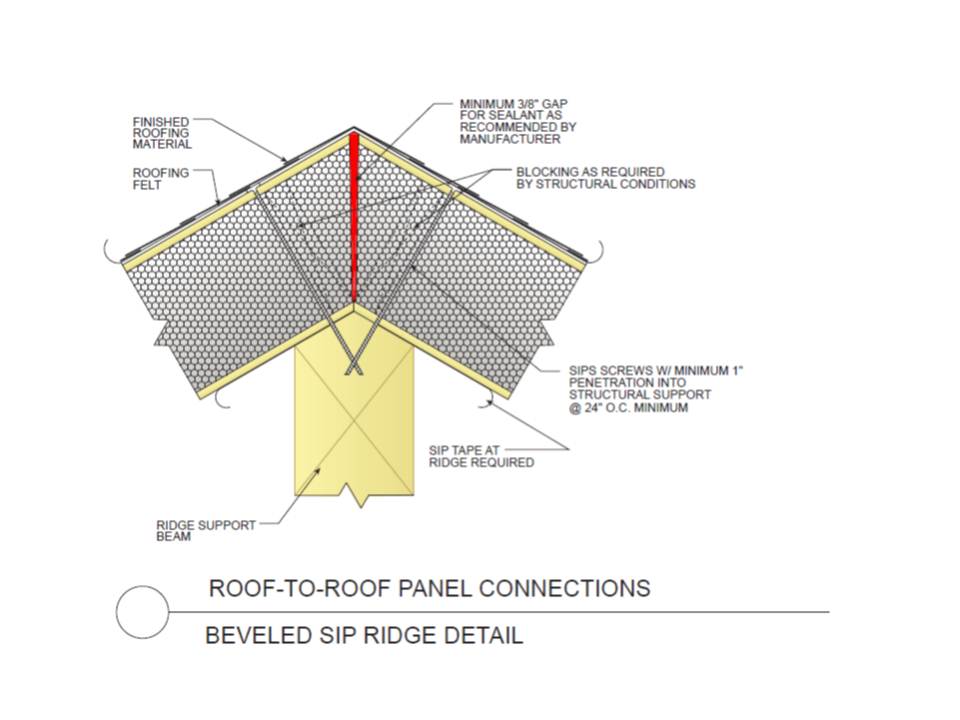
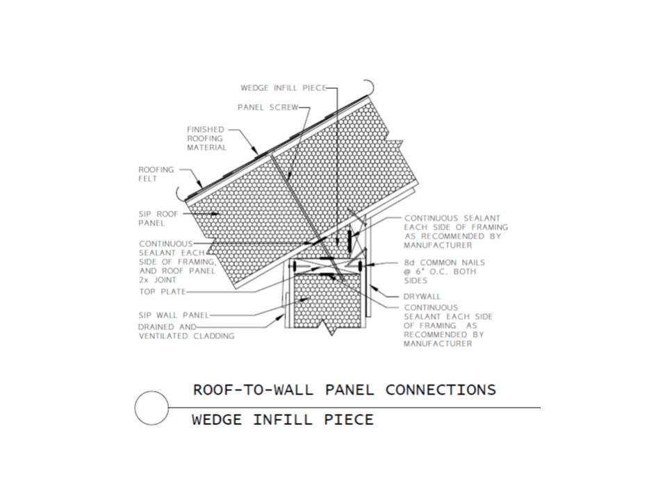
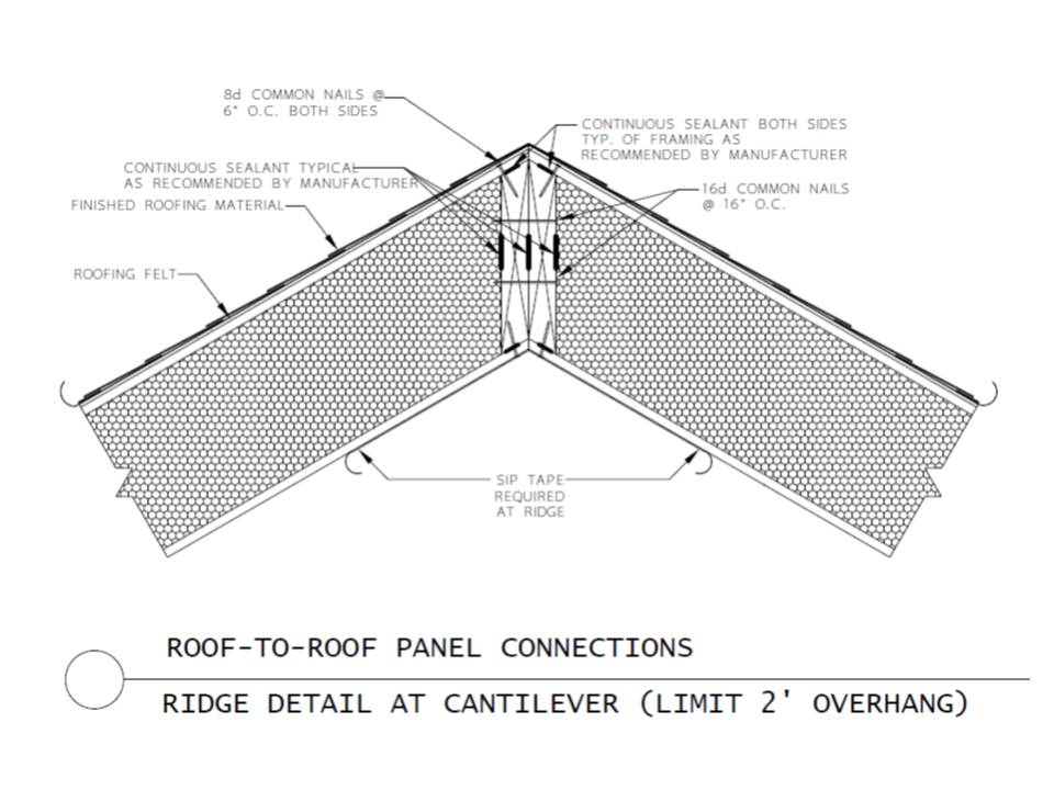
  • When applying tape to roof panels, start from the lowest point of the panel and continue upward.

See the Compliance Tab for links to related codes and standards and voluntary federal energy-efficiency program requirements.

Description

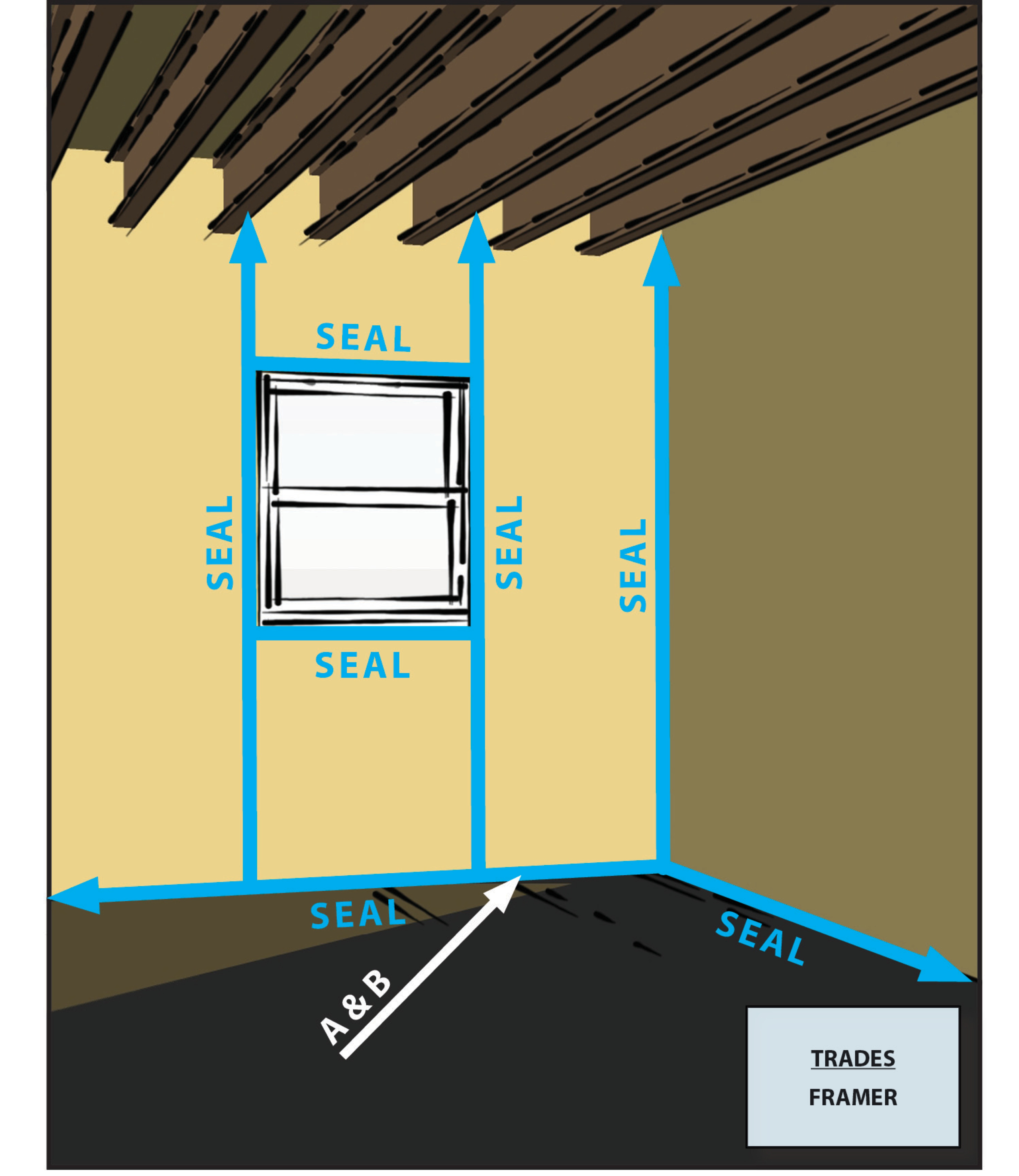
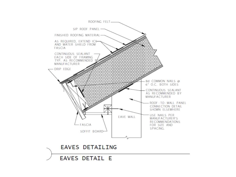
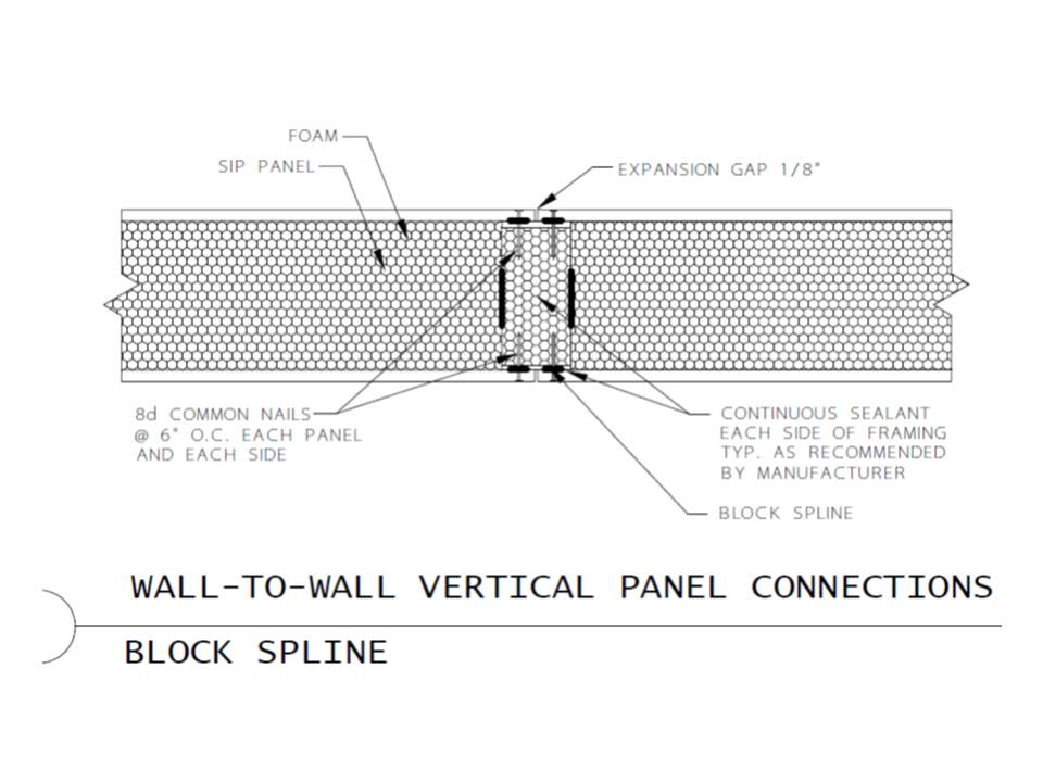
SIPs consist of two layers of plywood or OSB that “sandwich” an inner core of insulating rigid foam. Panels are spliced together using splines, consisting of strips of OSB, SIPs, or 2x4 or 2x6 lumber. The seams where one panel joins another are susceptible to air leakage. To form an air tight bond, spray foam or caulk is applied to the seams before the panels are connected. Many SIP manufacturers will provide the caulk and instructions. The wall-floor, wall-wall, and wall-roof seams can each require as many as six beads of caulk, and the roof ridge seam can require up to 8 beads of caulk.

After caulking, the panels are fit together to assemble the structure. To ensure that joints lock tightly together, a belt winch can be used to pull wall assemblies together; this is especially helpful with larger panels. Before drywalling, the seams can be covered with peel and stick tape as a second layer of protection against air leakage. Before installing drywall is also an ideal time to test the air tightness of the seams with a blower door test and smoke pencil to visually identify the location of any leaks.

Air barrier effectiveness is measured at the whole-house level. High-performance branding programs and the 2009 International Energy Conservation Code (IECC) require that builders meet specified infiltration rates at the whole-house level. See the “compliance” tab for these specified infiltration rates.

For more information on SIP installation, see Structural Insulated Panels.

How to Seal SIP Seams

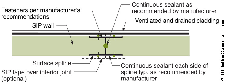
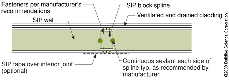
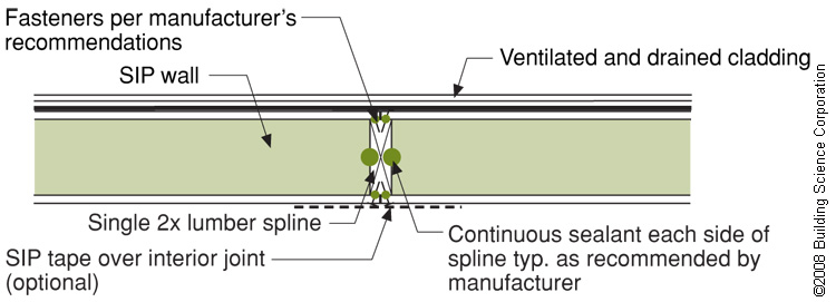
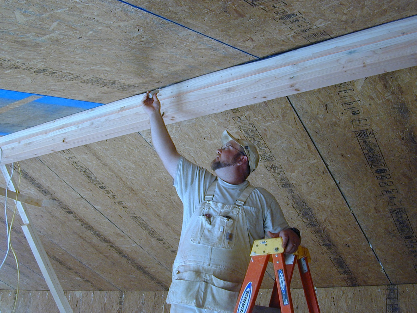
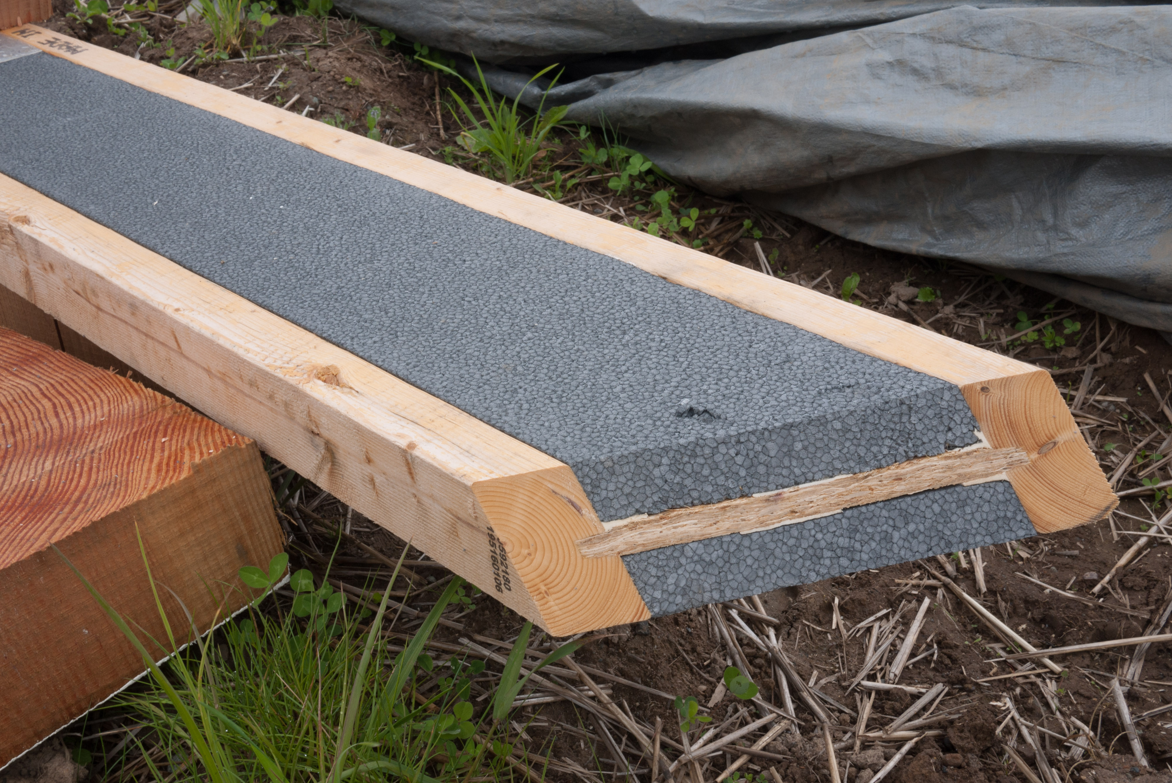
  1. Connect the panels with splines. The three most common splines are surface splines, insulated splines, and structural spines (see Figures 1, 2, and 3). To minimize thermal bridging, only use structural splines when needed to carry the structural load. Splines can be installed on one side of the panel in the factory; this can save assembly time at the site.
A surface spline reduces thermal bridging much more than a structural spline at SIP panel seams
Source
Figure 1. A surface spline reduces thermal bridging much more than a structural spline at SIP panel seams (Source: Builders Guide to Structural Insulated Panels (SIPs) for all Climates 2008). 
An insulated spline is another option for avoiding thermal bridging at SIP panel seams
Source
Figure 2. An insulated spline is another option for avoiding thermal bridging at SIP panel seams (Source: Builders Guide to Structural Insulated Panels (SIPs) for all Climates 2008). 


A structural spline made of a solid 2x is used where needed to meet structural load requirements at SIP panel seams
Source
Figure 3. A structural spline made of a solid 2x is used where needed to meet structural load requirements at SIP panel seams (Source: Builders Guide to Structural Insulated Panels (SIPs) for all Climates 2008). 
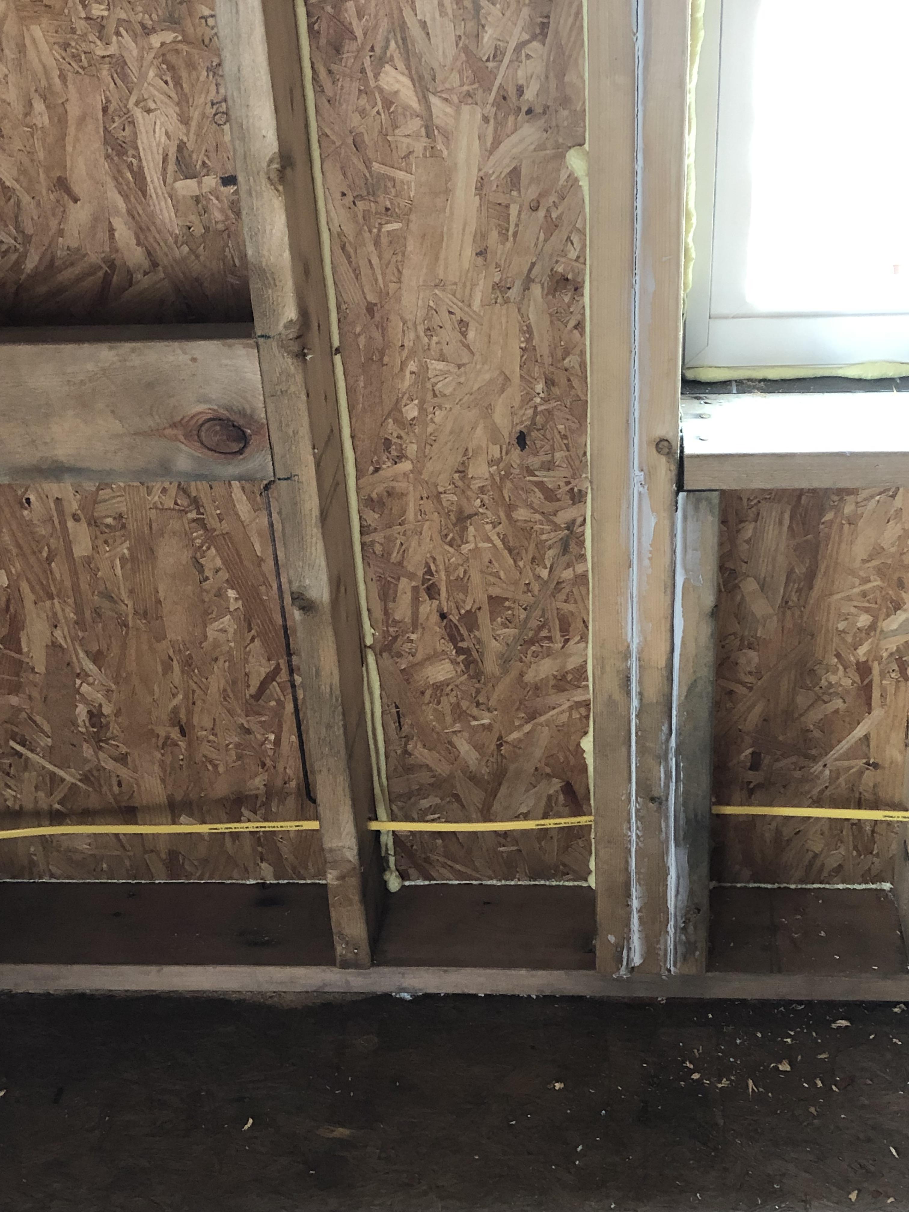
  1. Caulk on each side of the spline. Use caulk from the manufacturer, if provided. Follow the caulking schedule required by the SIP manufacturer for the number of beads of caulk to use at each type of seam. Make sure the beads are continuous. Consider using a power caulker; even in a small (1,200 sq. ft.) home, the amount of caulk required can total over 5,000 lineal feet of caulk.
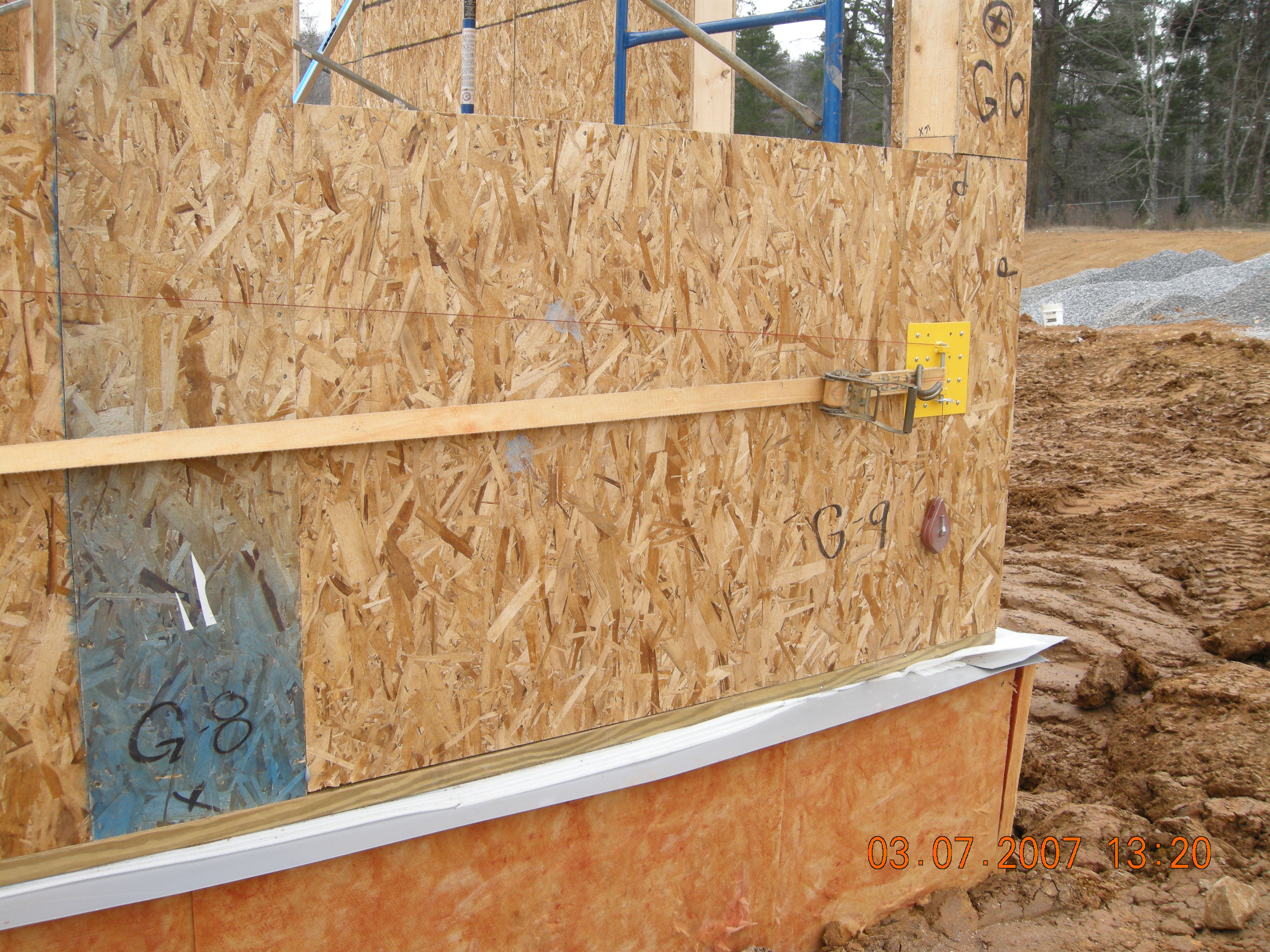
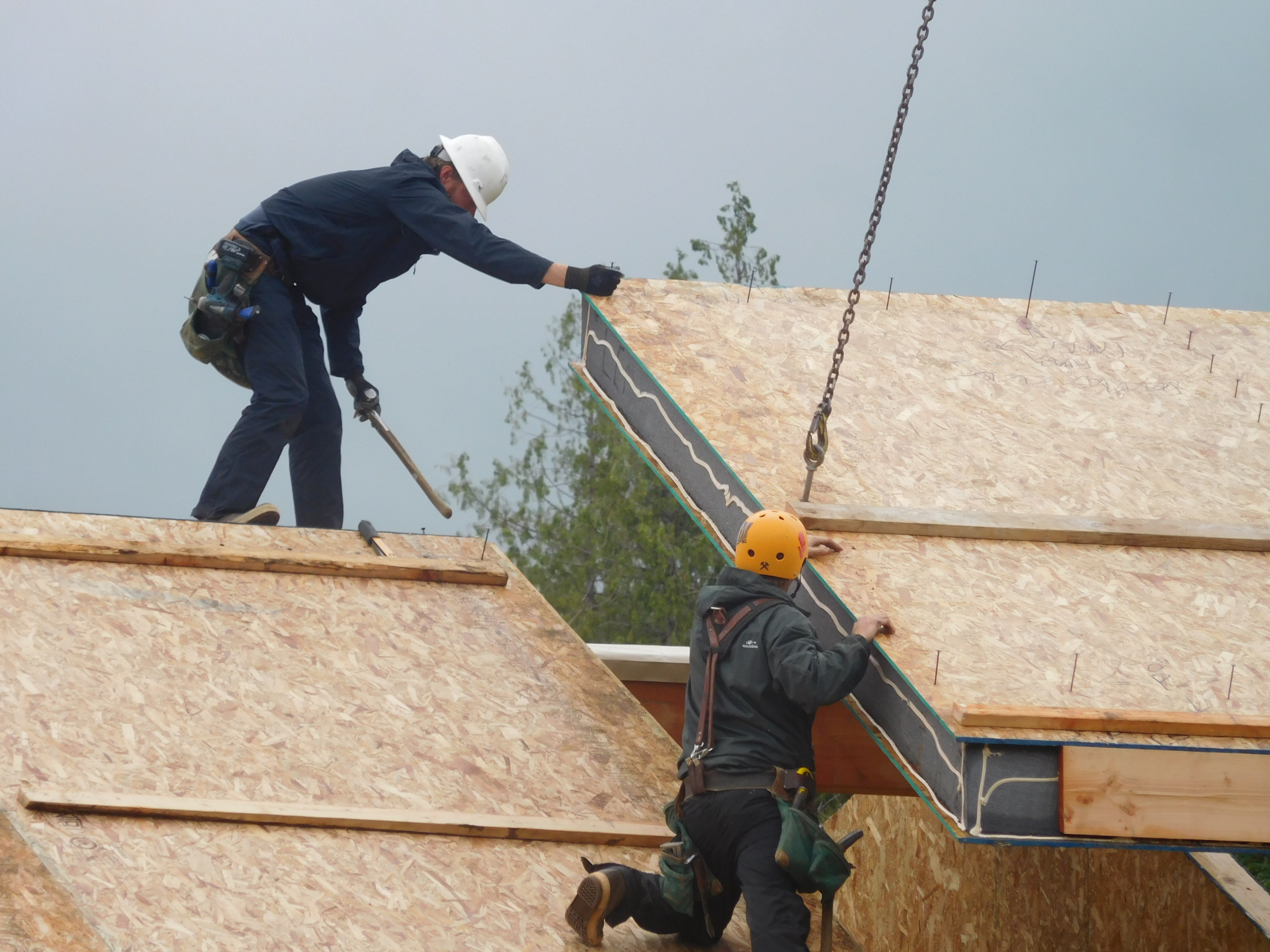
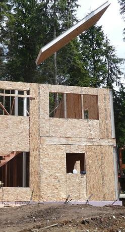
  2. Assemble the walls and roof. Use a fork lift and crane to place panels. Use lift plates and a belt winch (available from the manufacturer) to pull panels together tightly, if needed (Figure 4).
Lifting plates attached to the wall provide good bracing to tighten up SIP panel seams
Source
Figure 4. Lifting plates attached to the wall provide good bracing to tighten up SIP panel seams (Source: Courtesy of PNNL). 
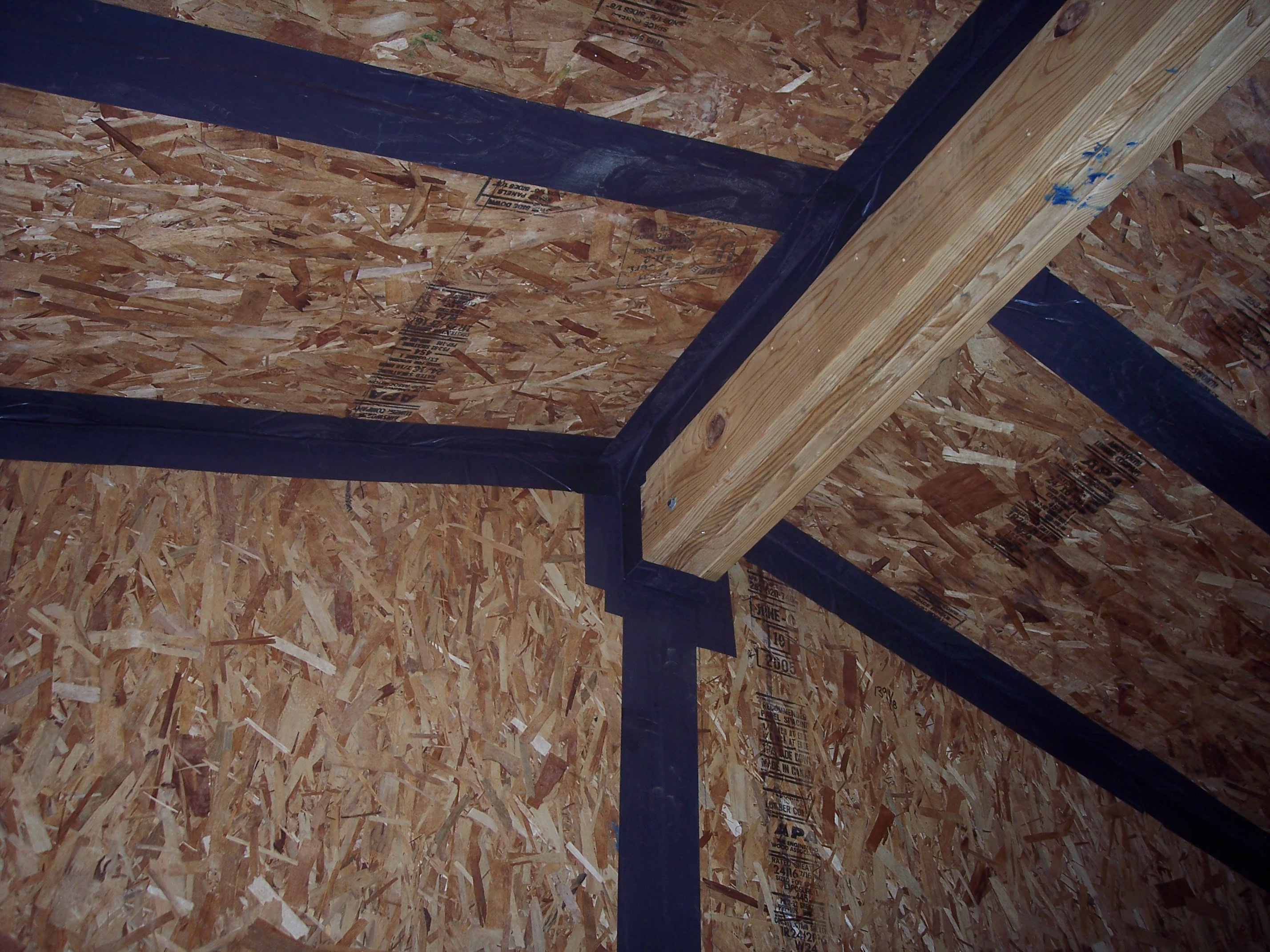
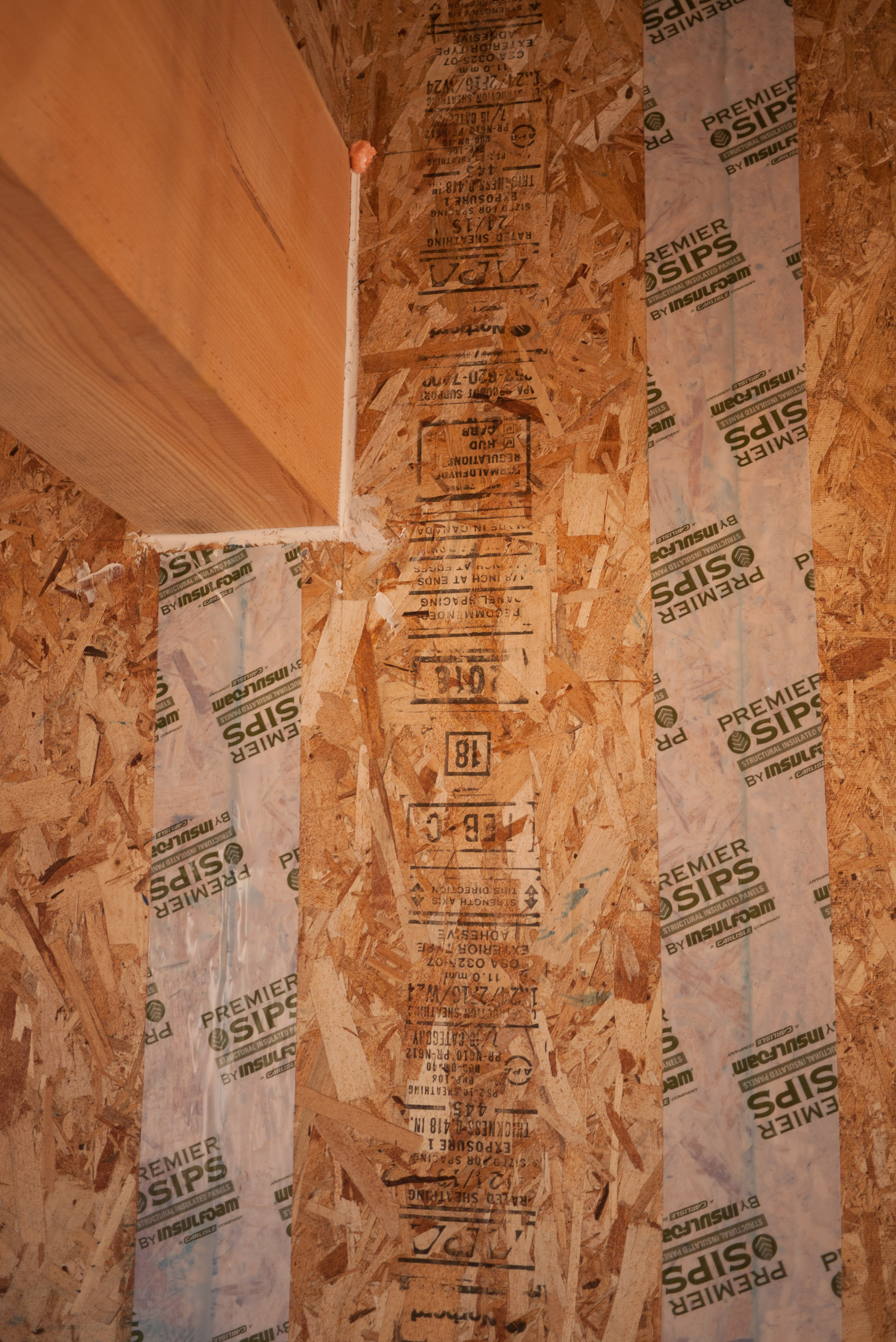
  1. Install peel-and-stick tape at panel-to-panel seams and at the ridge and wall-roof interface (See Figure 5).
Peel-and-stick panel tape provides added assurance that SIP panel seams will remain airtight
Source
Figure 5. Peel-and-stick panel tape provides added assurance that SIP panel seams will remain airtight (Source: Courtesy of PNNL). 
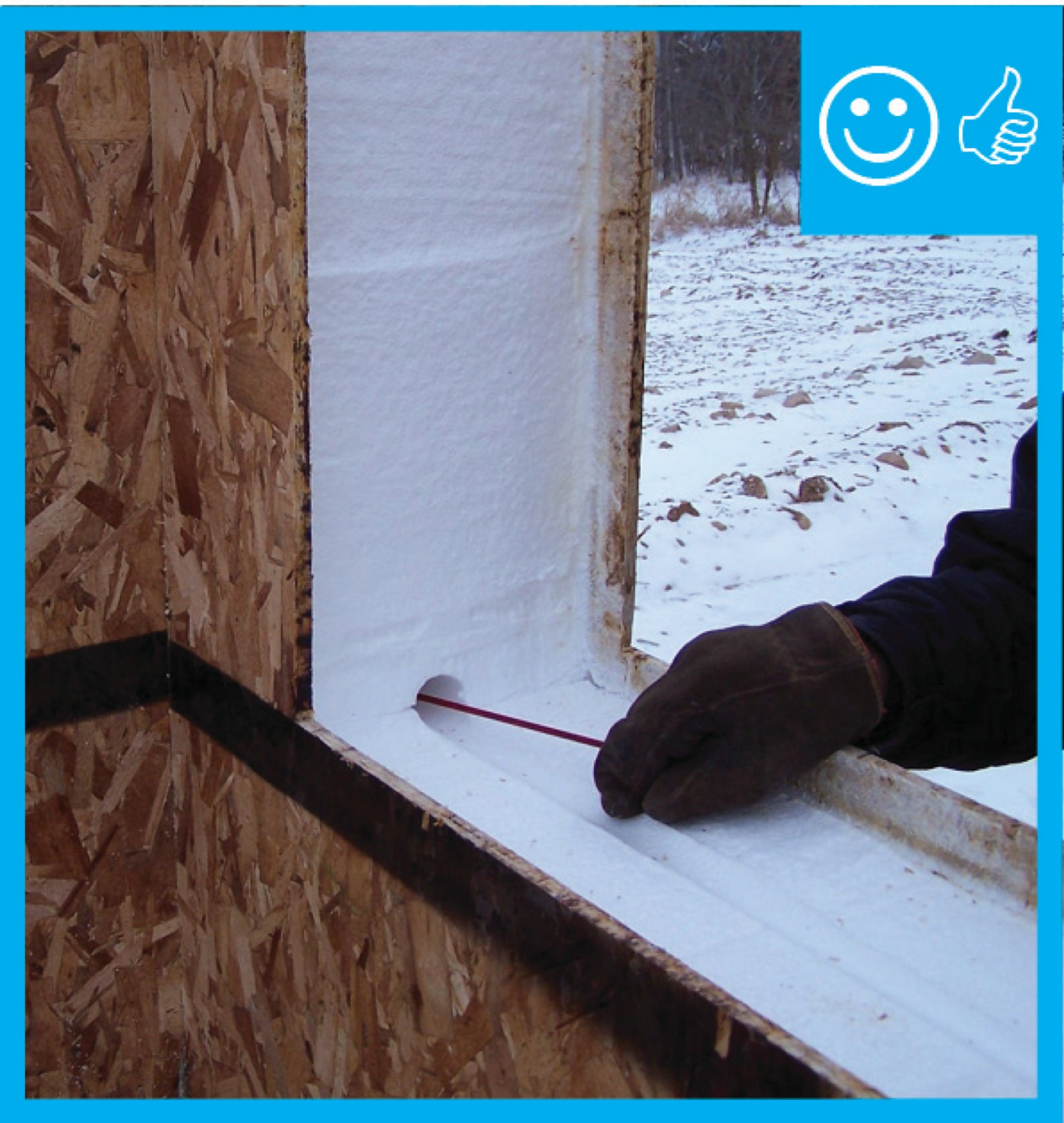
  1. Prior to drywalling, conduct a blower door test and use a smoke pencil to ensure that panel seams are tight (Figure 6).
Use a smoke pencil to check for air leaks at SIP panel seams, especially along the ridge beam
Source
Figure 6. Use a smoke pencil to check for air leaks at SIP panel seams, especially along the ridge beam (Source: Courtesy of PNNL). 

Ensuring Success

The air tightness of the envelope assembly of a home constructed with structural insulated panels can be easily tested by conducting a whole-house blower test prior to dry wall installation. While the house is depressurized, inspect all panel seams with a smoke stick. An infrared camera may also be helpful in spotting air leakage, if a sufficient temperature difference exists between the outside and the inside of the home. 

Region

No climate-specific information applies.

Training

Right and Wrong Images

Right - Hole drilled to verify sealant is present - Hole will be sealed after verification
Source
Author(s)
U.S. Environmental Protection Agency,
ENERGY STAR
Organization(s)
EPA
Description

Guide describing details that serve as a visual reference for each of the line items in the Thermal Enclosure System Rater Checklist.

Right – Tape seals the SIP panel seams.
Source
Right – All wood-to-wood joints are sealed with caulk.
Source
Right – A double bead of sealant seals the seams between the SIP panel and spline.
Source
Right – An insulated spline reduces heat transfer at the SIP panel joints.
Source

CAD Files

Connection of two SIP wall panels at a corner
Download: DWG PDF
Connection of a concrete foundation wall to SIP wall panel with a sill plate and floor joist
Download: DWG PDF
Connection of a SIP roof panel to a SIP roof panel with a foam ridge cap
Download: DWG PDF
Connection of two SIP roof panels with beveled edges at roof ridge
Download: DWG PDF
Connection of a SIP roof panel to a beveled SIP wall panel
Download: DWG PDF
Connection of the first floor and second floor wall panels with a hanging floor
Download: DWG PDF
SIP roof panel detailing at eaves with an angled fascia
Download: DWG PDF
Connection of roof truss to wall panel
Download: DWG PDF
Connection of concrete foundation to SIP wall panel
Download: DWG PDF
Connection of foundation wall to rim joist to SIP wall panel
Download: DWG PDF
Connection of a SIP roof panel to a SIP wall panel with a wedge infill piece
Download: DWG PDF
Connection of two SIP roof panels with beveled edges at roof ridge  with support for roof cantilever overhang
Connection of two SIP roof panels with beveled edges at roof ridge with support for roof cantilever overhang
Download: DWG PDF
Connection of first and second floor SIP wall panels with a floor joist in between
Download: DWG PDF
SIP roof panel detailing at the eaves with a vertical fascia and soffit board
Download: DWG PDF
SIP roof panel detailing at the eaves with a framed overhang, a vertical fascia and soffit board
Download: DWG PDF
SIP roof panel detailing at the eaves with a short overhang, a vertical fascia and soffit board
Download: DWG PDF
SIP roof panel detailing at the eaves with an angled fascia and soffit board
Download: DWG PDF
Connection of SIP wall panels with dimensional lumber splines
Download: DWG PDF
SIP panel door and wall framing
Download: DWG PDF
Connection of SIP wall panels with block splines
Download: DWG PDF

More Info

References and Resources

Publication Date
·
Author(s)
U.S. Environmental Protection Agency,
ENERGY STAR
·
Organization(s)
EPA
Description
Guide describing details that serve as a visual reference for each of the line items in the Thermal Enclosure System Rater Checklist.
Publication Date
·
Author(s)
Christian Jeffrey E,
Beal David,
Kerrigan Philip
·
Organization(s)
Oak Ridge National Laboratory,
ORNL,
Florida Solar Energy Center,
FSEC,
Building Science Corporation,
BSC
Description
Paper describing testing for the first of a series of six near net-zero-energy test houses, using the results to work towards the construction of a true net-zero-energy house.
Publication Date
·
Author(s)
Christian Jeffrey E
·
Organization(s)
Oak Ridge National Laboratory,
ORNL,
American Council for an Energy Efficient Economy,
ACEEE
Description
Report presenting construction methods, building products, appliances and equipment of four single-family houses that achieve dramatic energy reductions and approach “net zero energy” use.
Publication Date
·
Author(s)
U.S. Department of Energy
·
Organization(s)
DOE
Description
Website listing implementation timelines and links to various versions of the DOE Zero Energy Ready Home national program requirements.
Publication Date
·
Author(s)
U.S. Environmental Protection Agency
·
Organization(s)
EPA
Description
Website providing the technical specifications and related documents for home builders, subcontractors, architects, and other housing professionals interested in certifying a home to the EPA's Indoor airPLUS program requirements.
Publication Date
·
Author(s)
ENERGY STAR
·
Organization(s)
ENERGY STAR
Description
Website showing compliance timelines for various versions of the ENERGY STAR Single-Family New Home program requirements with links to national program requirements documents and checklists.

*For non-dated media, such as websites, the date listed is the date accessed.

Sales

Building Science-to-Sales Translator

Structural Insulated Panels (SIPs) = SIP Thermal Blanket

Image(s)

Technical Description

Structural insulated panels (SIPs) are a sandwich made up of foam insulation glued between two layers of sheathing (e.g., oriented strand board, magnesium oxide board, or drywall). SIP wall and roof panels are produced in a factory and come to the job site clean, dry, straight, and precisely made to the wall dimensions specified in the house plans with precut openings for doors and windows. They assemble quickly, producing a sturdy, well-sealed, well-insulated structure. Because there is minimal to no framing, the foam core provides a nearly continuous thermal blanket around the entire structure so heat transfer through the framing is greatly reduced.

SIP Thermal Blanket
Sales Message

SIP thermal blanket construction blocks excessive heat loss and gain though structural framing. What this means to you is less wasted energy along with enhanced comfort and quiet. Knowing there is one opportunity during construction to lock in quality construction, wouldn’t you agree advanced thermal protection is a great investment?

Last Updated

Questions? Comments? Contact our webmaster.

Disclaimer

This content is a work created with funding provided by the United States Department of Energy under Contract no DE-AC05-076RL01830 for the operation of Pacific Northwest National Laboratory. The information and guidance provided by Pacific Northwest National Laboratory (PNNL) in the content are intended solely for educational purposes only and do not constitute formal training or certification. It is provided with the explicit understanding that neither the United States Government nor the United States Department of Energy, nor the Contractor, nor any or their employees, nor any jurisdiction or organization that has cooperated in the development of these materials, makes any warranty, express or implied, or assumes any legal liability or responsibility for the accuracy, completeness, or usefulness or any information, apparatus, product, software, or process disclosed, or represents that its use would not infringe privately owned rights. Reference herein to any specific commercial product, process, or service by trade name, trademark, manufacturer, or otherwise does not constitute or imply its endorsement, recommendation, or favoring by the United States Government or any agency thereof, or Battelle Memorial Institute. The views and opinions of authors expressed herein do not necessarily state or reflect those of the United States Government or any agency thereof. Viewers assumes full responsibility for all actions that they may take from information provided in this content including ensuring the safety, code compliance, and proper functionality of any products they choose to install. Installation and use of such products should be performed in accordance with local regulations and manufacturer instructions.