
Structural Insulated Panels (SIPs)

    Scope
    Scope Images
    Image
    Construct exterior walls with structural insulated panels (SIPs) to provide an air-tight wall with consistent insulation and very little thermal bridging.
    Scope

    Construct exterior walls with structural insulated panels (SIPs) to provide an air-tight wall with consistent insulation and very little thermal bridging.

    • Design and construct SIP walls according to manufacturer’s specifications.
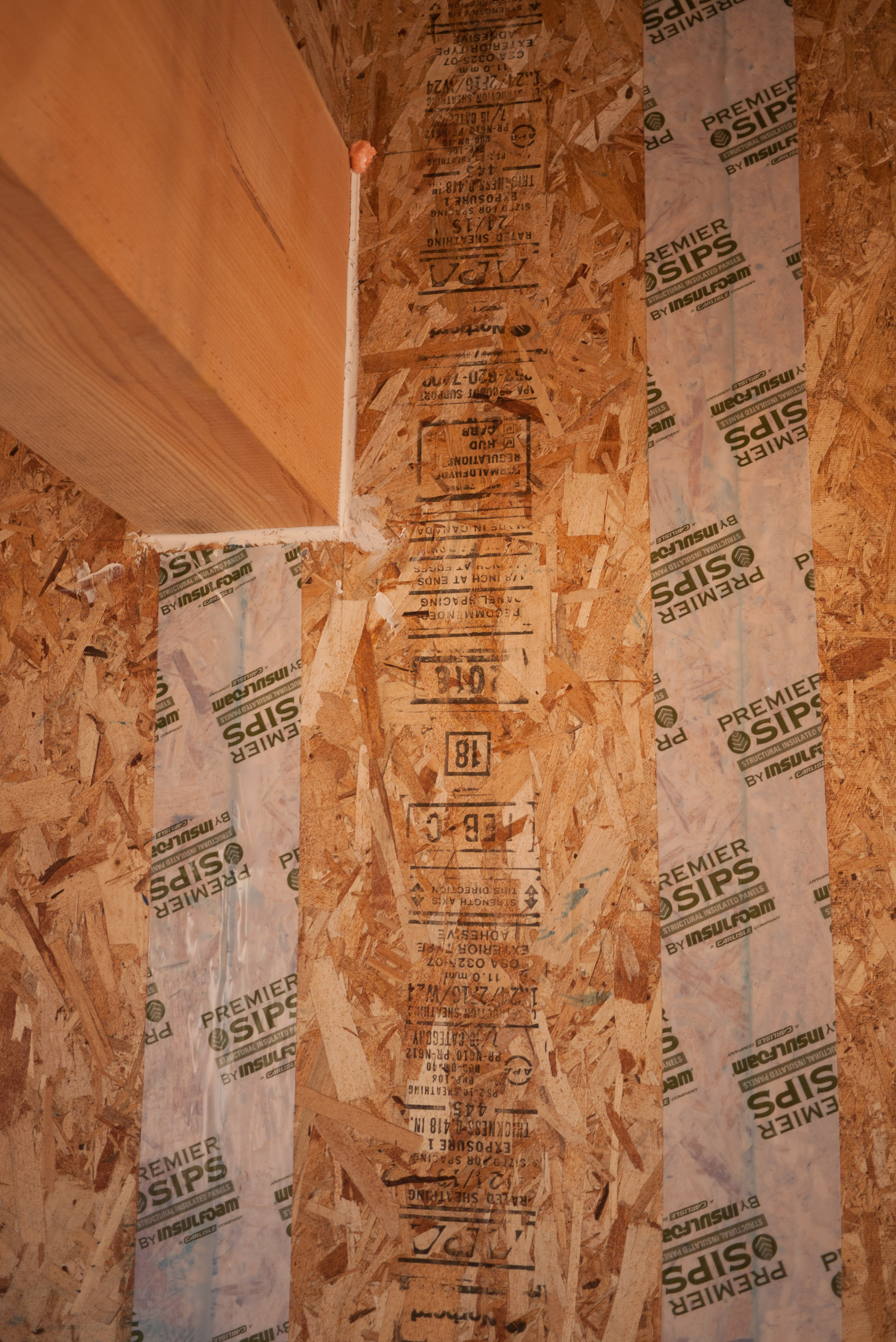
    • Seal all seams between SIPs following manufacturer's specifications.
    • Obtain engineering approval if required. The IRC provides a prescriptive pathway for compliance of SIPs, although additional engineering review and approval may be required for SIP wall construction in areas that are subject to high wind speeds and areas that are prone to earthquakes.

    See the Compliance Tab for related codes and standards requirements, and criteria to meet national programs such as DOE’s Zero Energy Ready Home programENERGY STAR Single-Family New Homes, and EPA Indoor airPLUS.

    Description
    Description

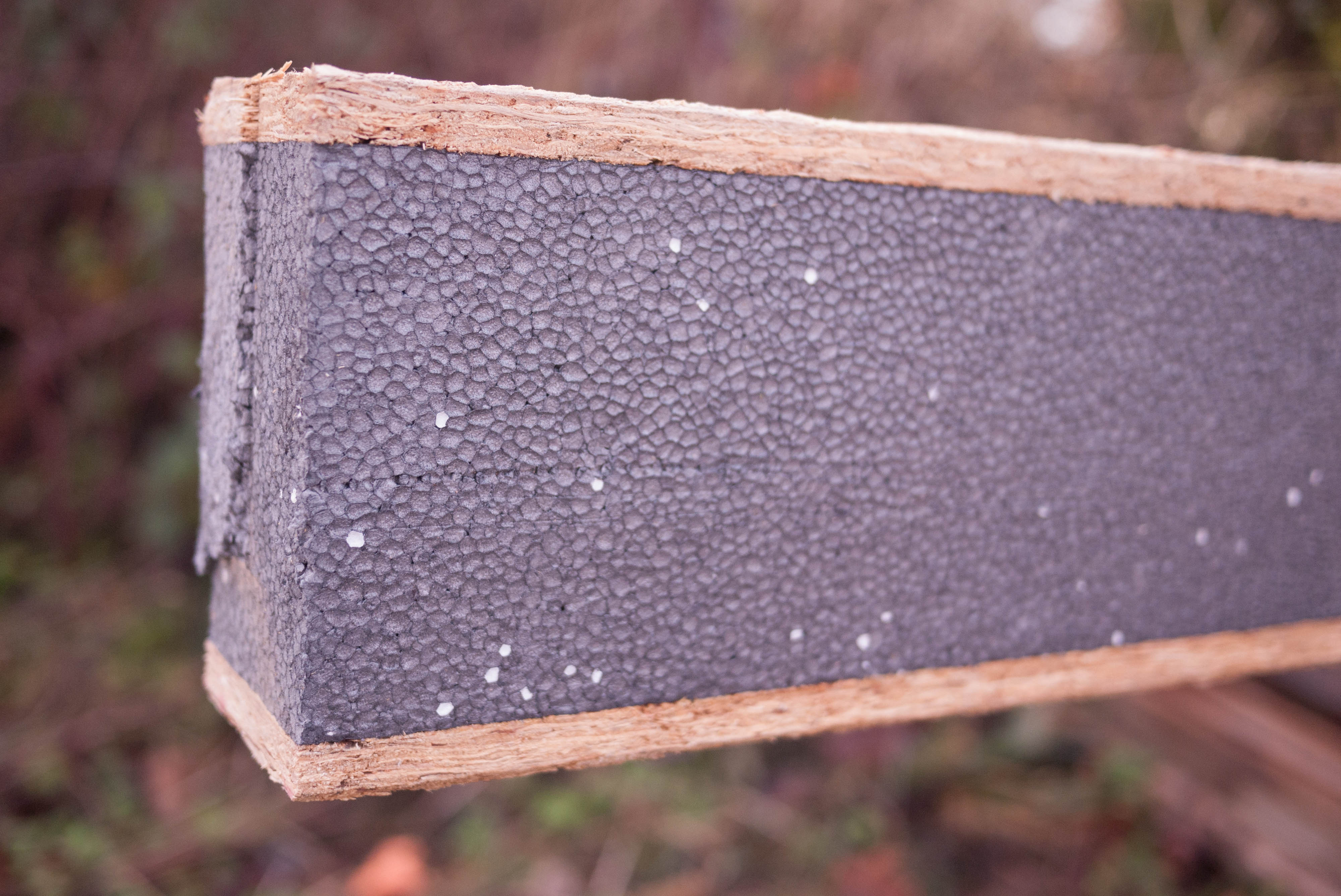
    SIPs consist of two layers of plywood or OSB that “sandwich” an inner core of insulating rigid foam. SIP walls meet or exceed typical dimensional lumber construction structural properties. Because less framing is needed with SIP panels, there is also less thermal bridging than in a stick-built wall. Studies have found that framing comprises 25% of a stick-built wall and 14% of an advanced framed wall but only 8.7% of a SIP wall (CEC 2001; Carpenter and Schumacher 2003).

    SIP panel walls are less susceptible to air leakage and convection and resultant potential condensation problems than stick-built walls (see Figure 1).

    SIP panel walls are less susceptible to air leakage and convection and resultant potential condensation problems than stick-built walls.
    Figure 1. SIP panel walls are less susceptible to air leakage and convection and resultant potential condensation problems than stick-built walls.


    The following general guidance is provided when installing SIP panels. Also, follow the specific manufacturer’s instructions for the SIP product to be installed.

    How to Install SIP Panels

    When installing SIPs the ten most important considerations are the following (Christian 2011).

    1. Start with detailed plans.
      Meet with all subcontractors and key personnel before construction to review the plans and discuss sequencing. Either train yourself on SIP installation or have trained personnel involved in the project at as early a stage as possible. Know the location of structural point loads. Continuously check the accuracy of shop drawings to ensure the installation matches the intent of the plans. In general, the entire exterior wall needs to be supported all the way to the foundation. Plan for a single ridge beam if possible for simplicity of installation. The ridge beam generally has several intermittent load points that transfer the design load to the ground. Understanding where these load points are located is important to maintain not only the needed structural support within the conditioned space but also to maintain chase ways for HVAC, plumbing, and electrical distribution. Make sure that the window and door rough openings are correctly placed in precut panels. Avoid designs that call for ganged or mulled windows because they are heavy, awkward to handle, and harder to install. They also require more solid wood headers in the SIP panels, resulting in potential thermal bridging. Make sure that the HVAC chases are specified and maintained as construction proceeds. Make sure the electrical plan is complete and reflected in the panel cut drawings sent to you for your approval prior to panel fabrication. Keep all plumbing out of exterior walls and keep the electrical in exterior walls to the bare minimum. Run all vertical chases into floor spaces by routing from exterior to interior walls and then up or down. An excellent book to read before constructing your first SIP house is Building with Structural Insulated Panels by Michael Morley (Morley 2000).
    2. Protect the panels prior to installation.
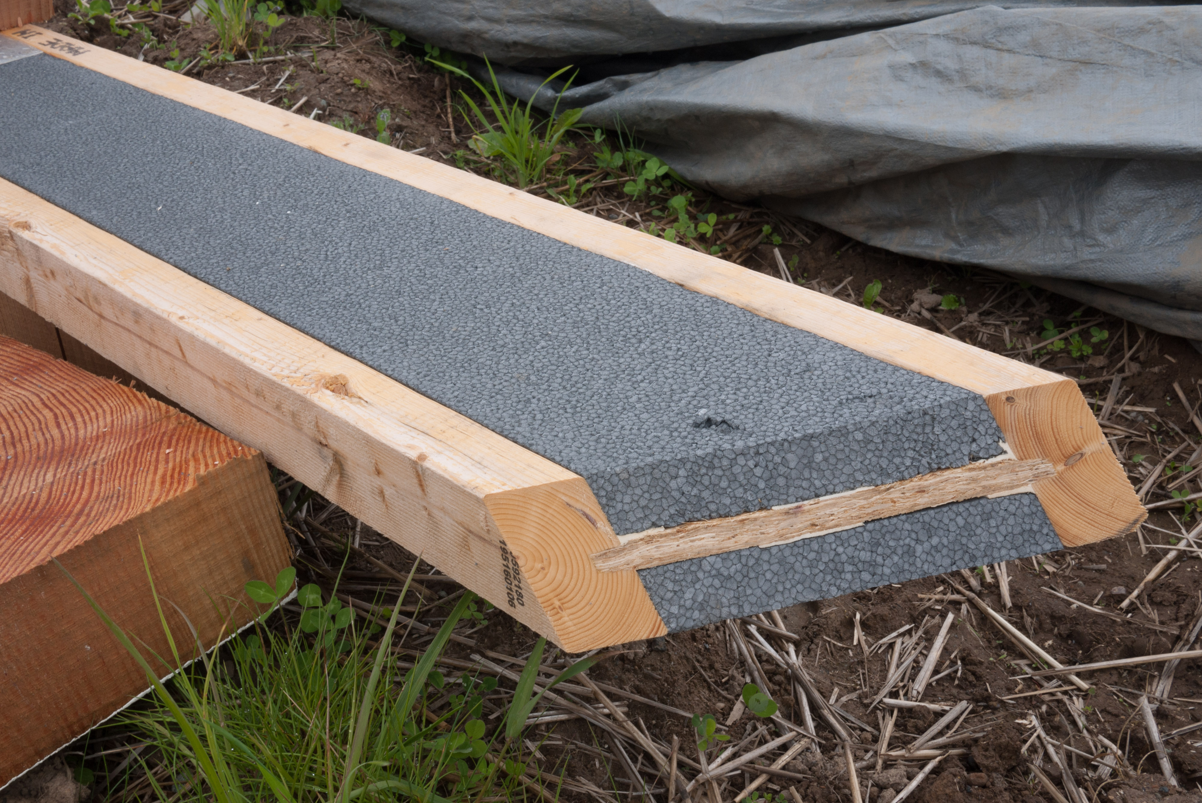
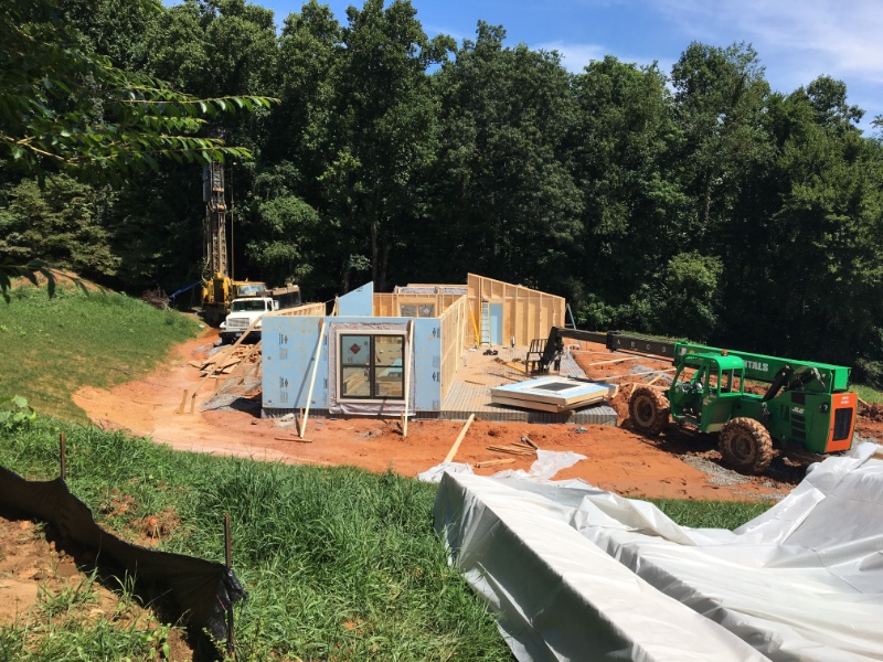
      Avoid damaged panels. Ideally have the foundation assembly completed just before the arrival of the panels. Coordinate with the SIP manufacturer to determine who will unload and stack the panels when they arrive at the work site, it is generally the contractor’s responsibility to unload the truck. To protect the panels and minimize handling, stack the panels high, dry, and flat and in the order they will be needed as when assembly begins. Manufacturers ship groups of panels that will be erected together. Panels should be stacked off the ground on 4 X 4 timbers no more than 6 ft. apart and covered with a tarp (Figure 2 and Figure 3). Avoid locating the stacks above standing water and wet soils. Place a ground cover down first to avoid soil moisture driving conditions transporting ground moisture up into the panels and causing edge swelling. Reusable tarps are easily held in place by wedging scraps of wood into the recessed cut-outs for the splines at the ends of the panels. Make sure the panels lay flat while stored on site.
      SIP panels should be stacked high, dry, and flat.
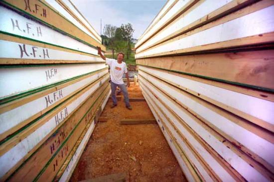
      Figure 2. SIP panels should be stacked high, dry, and flat.
       
      An all-terrain forklift is used to move and stage the panels.
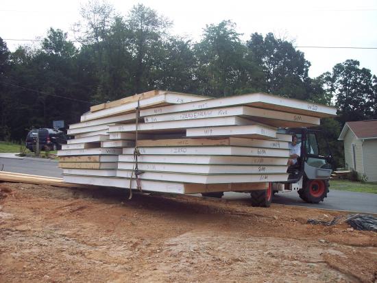
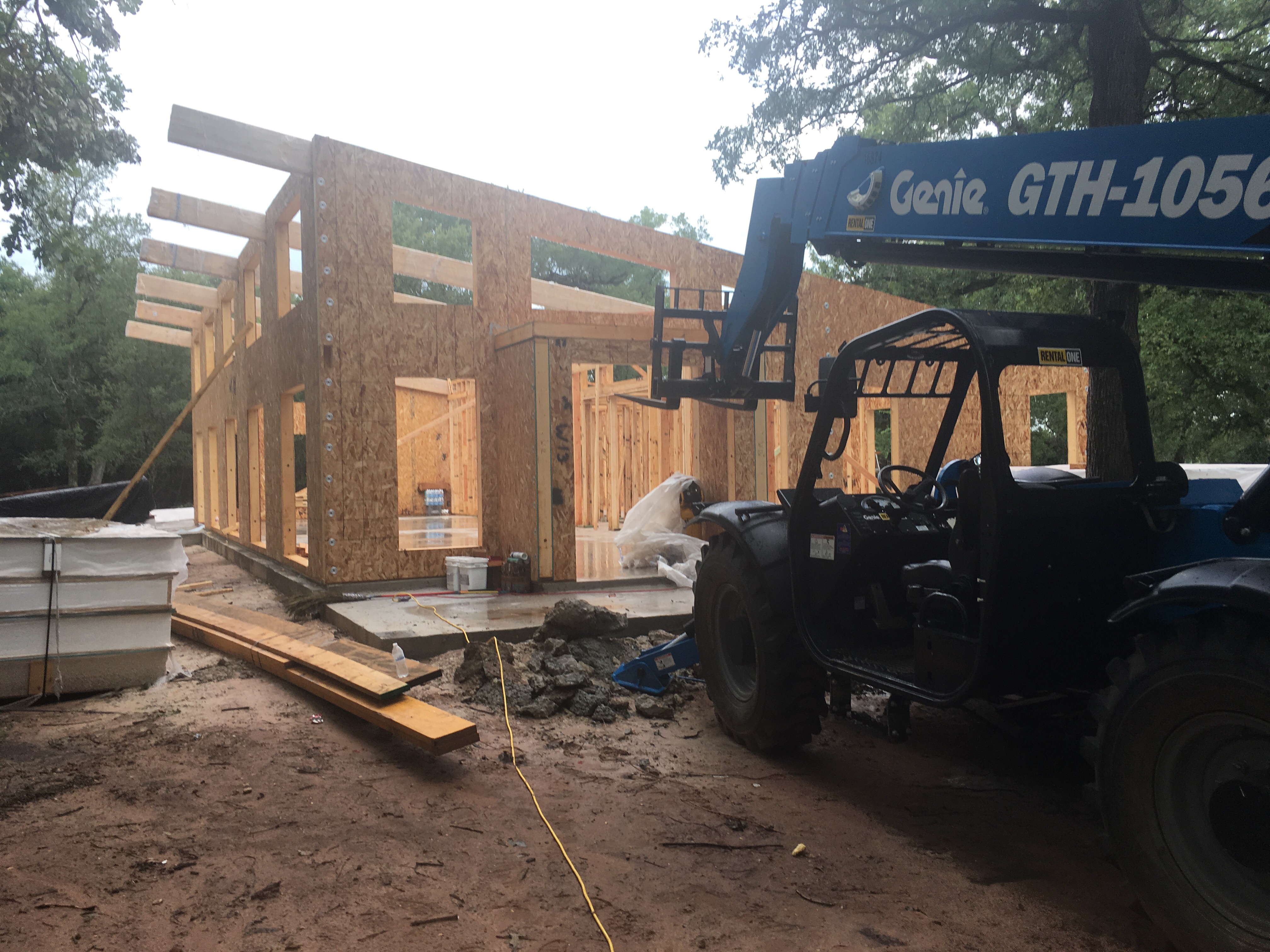
      Figure 3. An all-terrain forklift is used to move and stage the panels.
    3. Ensure the foundation is plumb, level, and square.
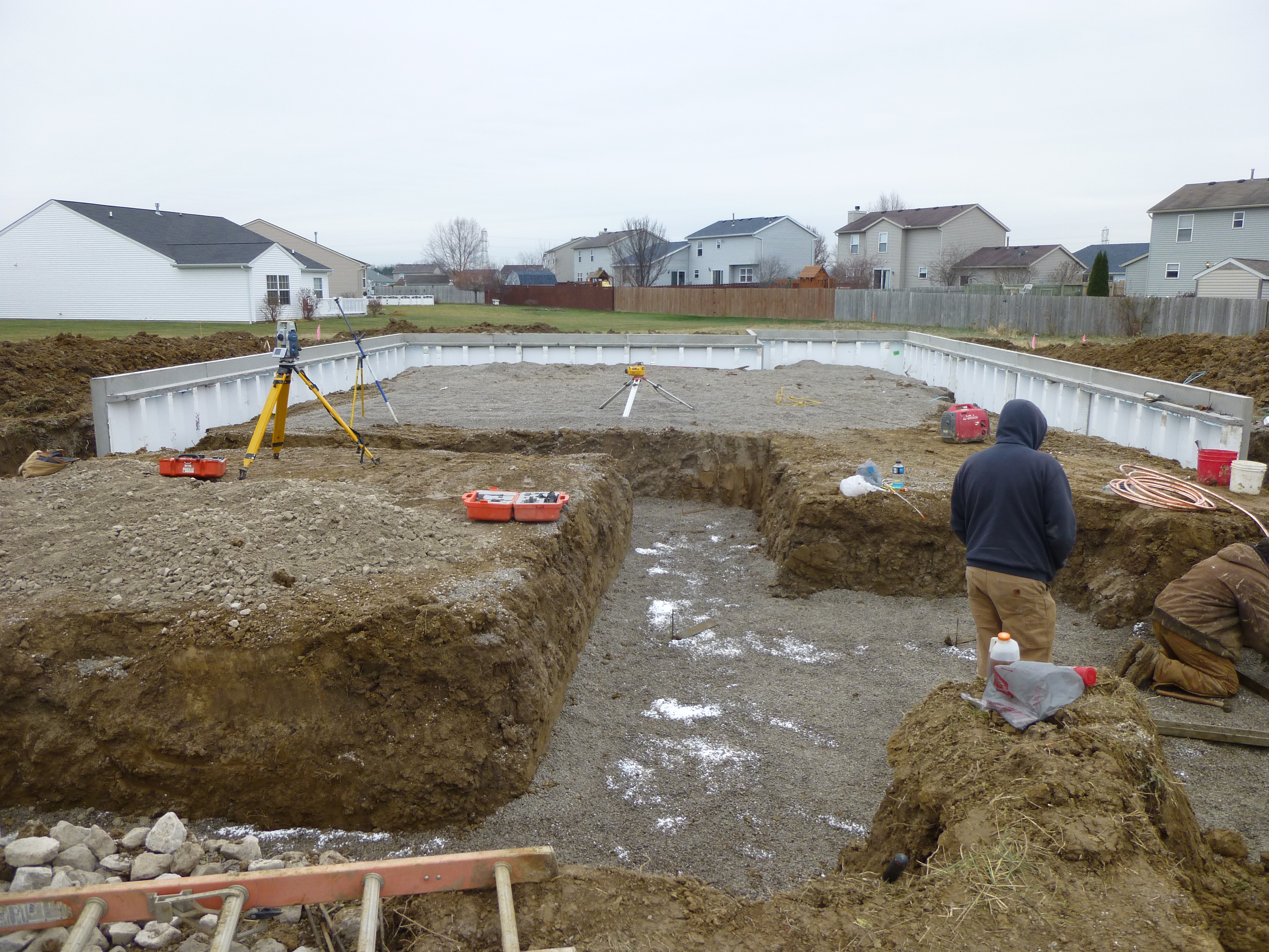
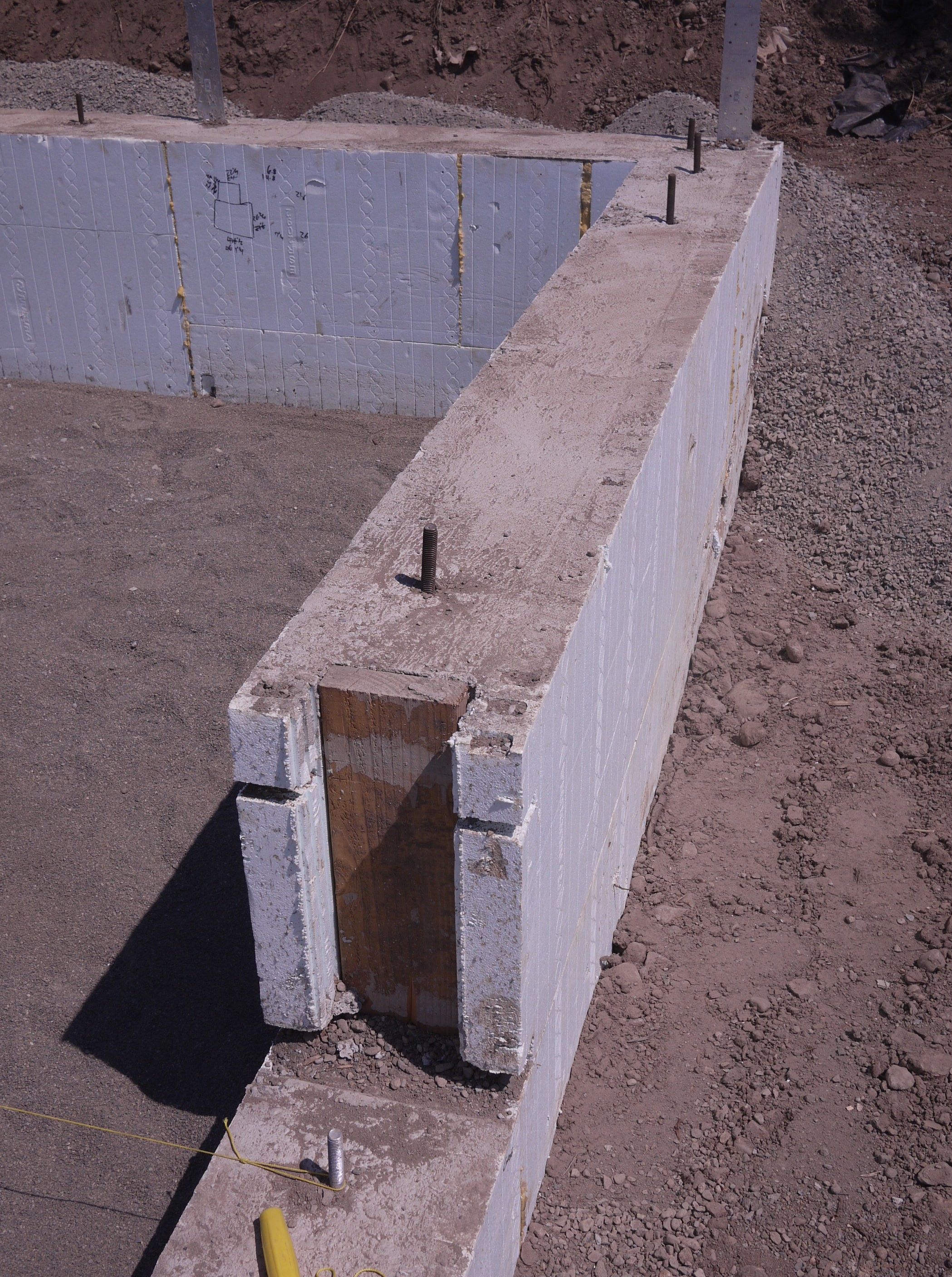
      There is less tolerance for foundations that are not level in SIP construction than in stick-frame construction. Double-check to make sure you have the right dimensions for the footer, foundation wall, and floor on the design drawings, and measure for confirmation of plumb, level, and square of the footer, foundation wall, and floor during construction. The concrete subcontractor needs to understand that a SIP foundation must be closer to plumb, level, and square than the typical residential construction industry accepted standard.

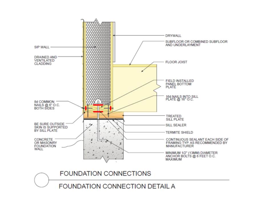
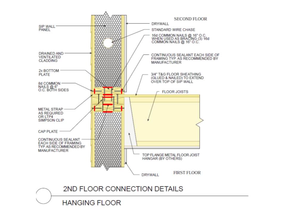
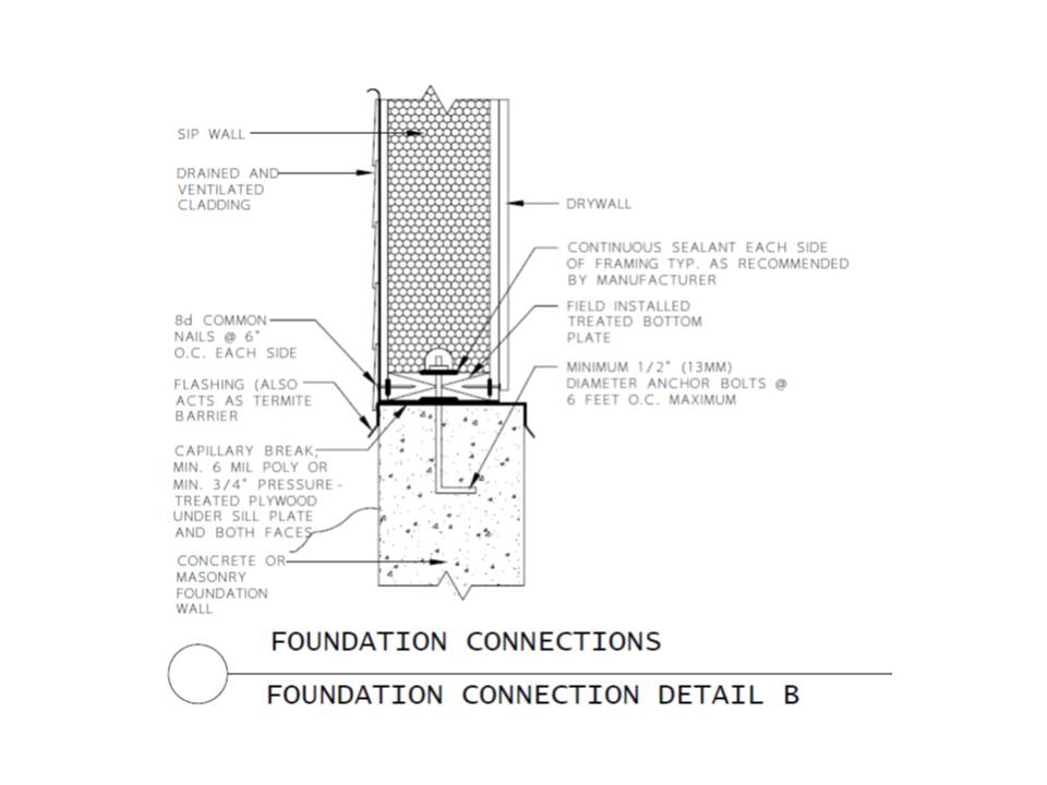
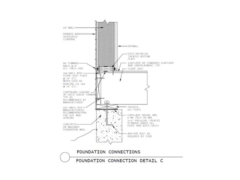
      Figure 4 shows the recommended foundation/floor/SIP wall detail. The outside facing of the SIP must have continuous structural support for the full length of the bottom edge. It should sit on, not hang over the edge of the top plate. Install a termite shield and capillary break between the sill plate and foundation wall; this can be aluminum flashing that covers the top of the foundation from the inside to outside wall surfaces.
      This foundation/floor/SIP wall detail shows the recommended way to support the SIP wall panel at the sill plate.
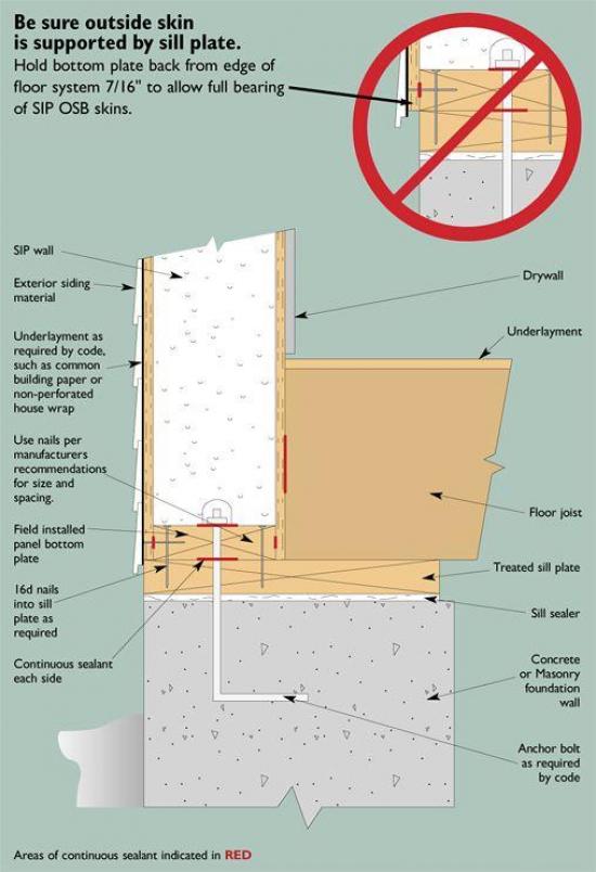
      Figure 4. This foundation/floor/SIP wall detail shows the recommended way to support the SIP wall panel at the sill plate.
    4. Assemble the Walls and Roof.
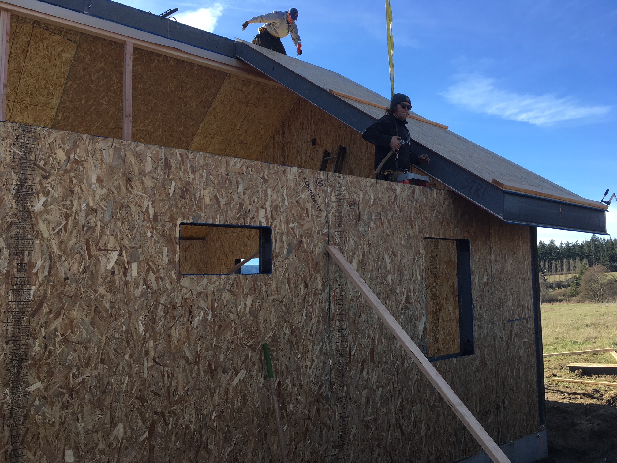
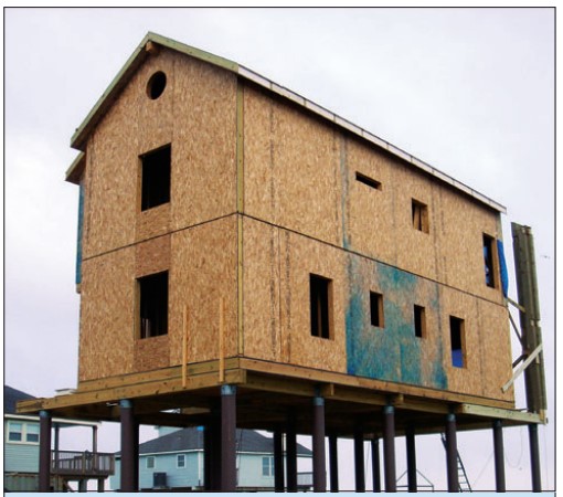
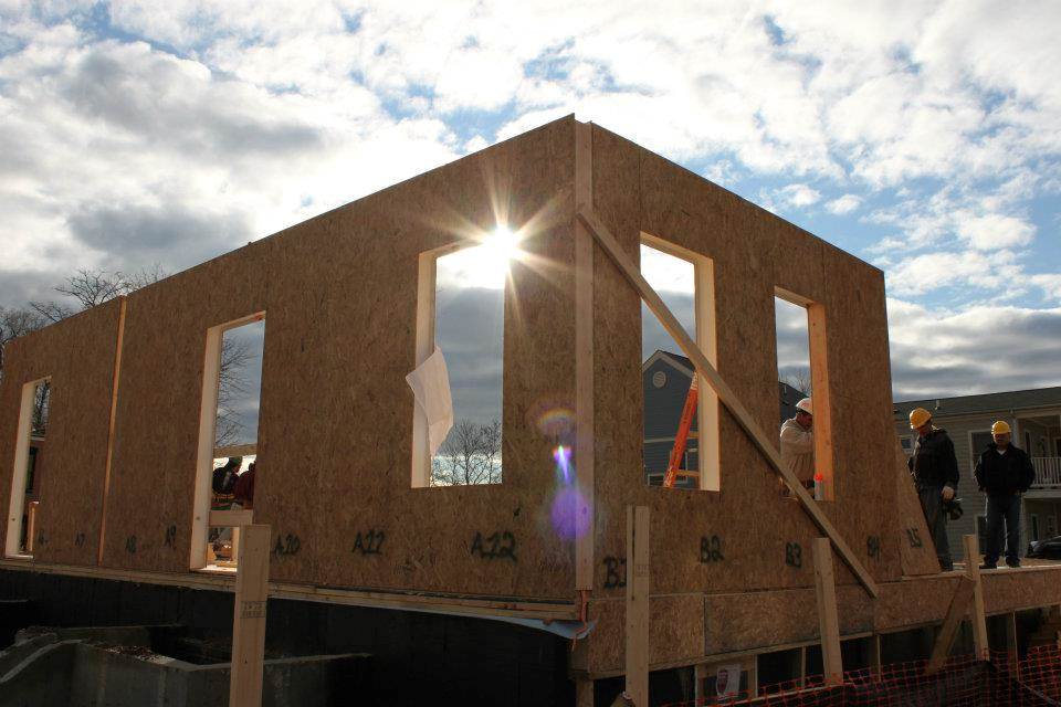
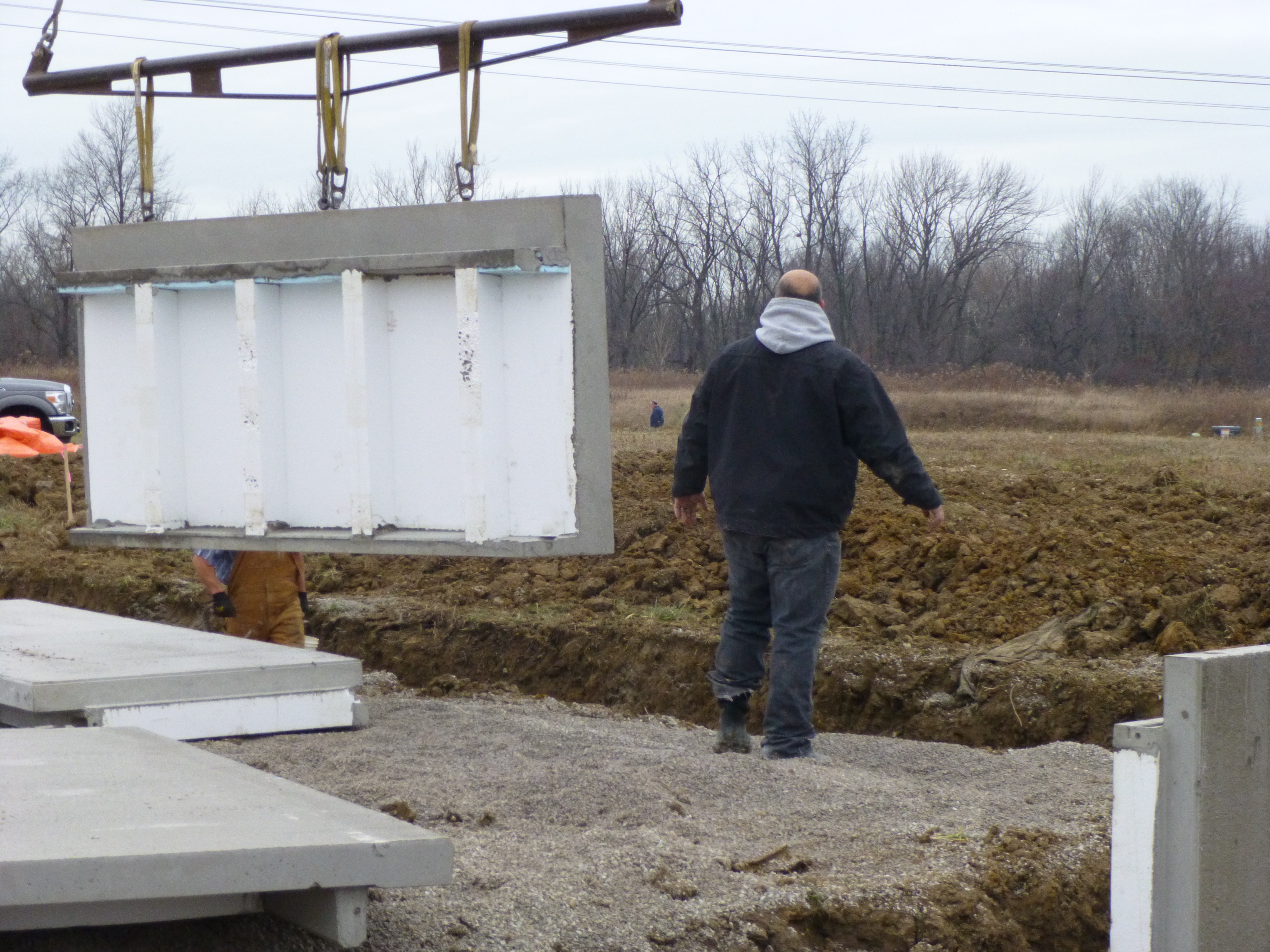
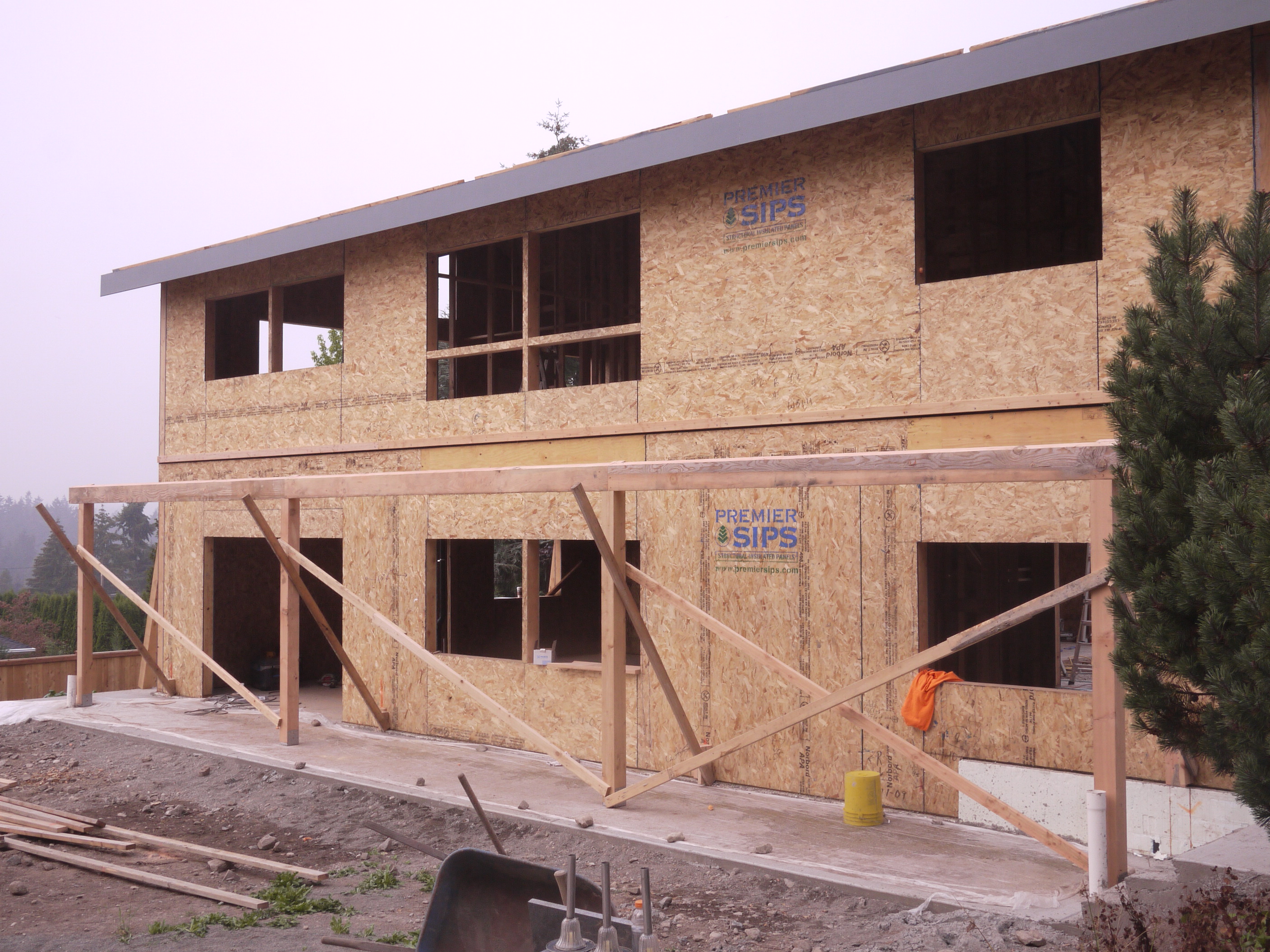
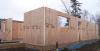
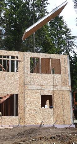
      For assembling the exterior walls there are two general approaches: 1) assemble 4x8-foot SIP panels manually or 2) assemble 10x24-foot panels with rough openings precut that are lifted in place with a crane or forklift with a high boom pole (See Figures 5 and 6). Larger wall panels have fewer seams, which reduces both thermal bridging and the risk of air leakage.

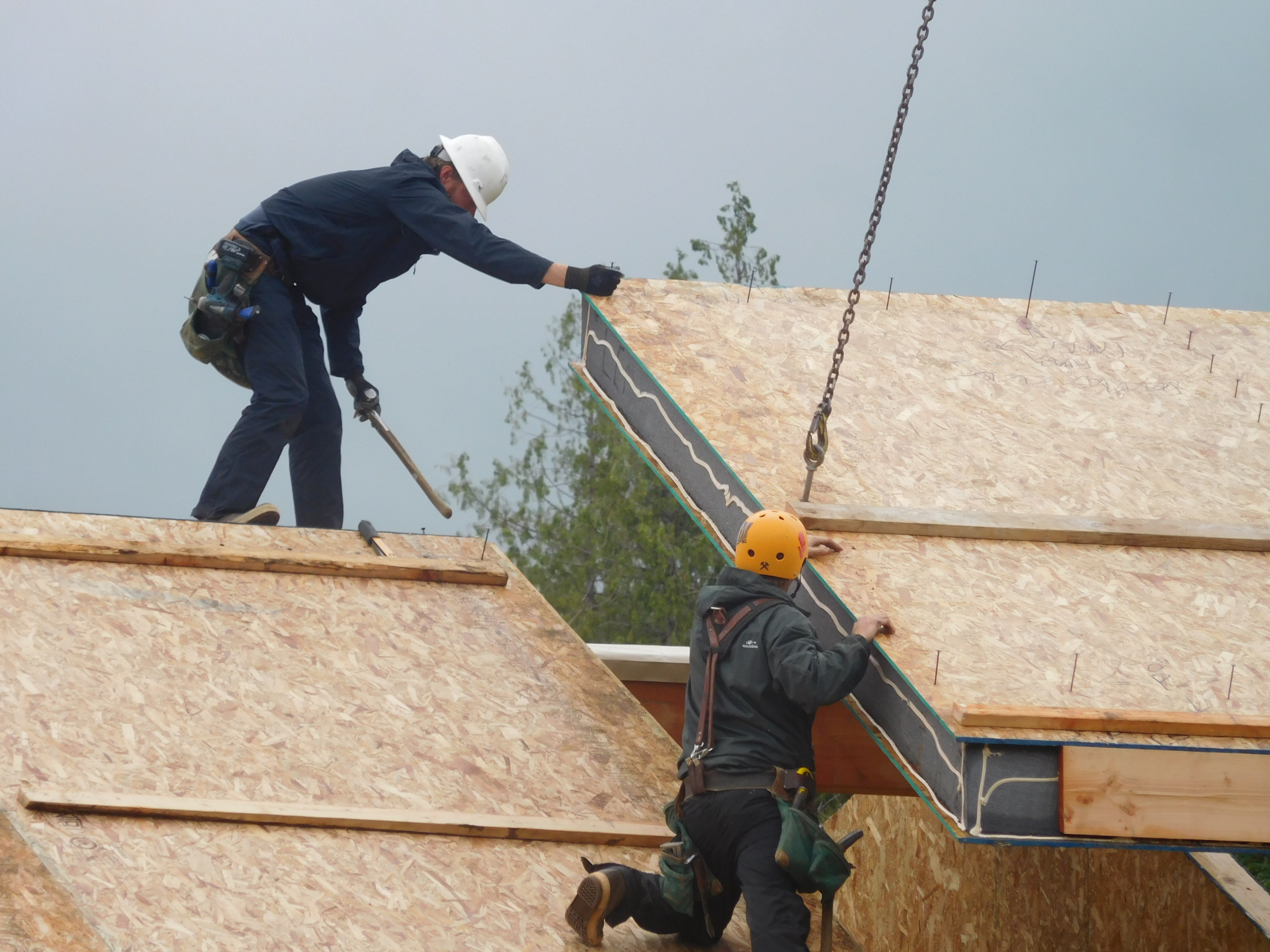
      For assembling the roof, use a boom truck and crane with proper rigging to lift the ridge beam and SIP ceiling panels. For quickest assembly, use a single ridge beam and have it available on site to lift in place as soon as the walls are up, plumbed, leveled, and squared. Lift the ridge beam in place with the boom truck and a rigger’s sling made up of double-choker hitches. Have the roof panels and crews in place so that once the crane arrives and the beam is placed, the roof panel placement can commence immediately, so that rigging time and costs are minimized.
      Walls are being assembled at this SIP house.
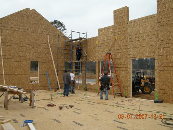
      Figure 5. Walls are being assembled at this SIP house.
       
      A crane is used to install the SIP fireplace chimney chase.
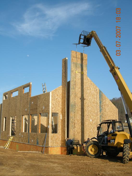
      Figure 6. A crane is used to install the SIP fireplace chimney chase.
    5. Connect the panels together.
      The SIP package will have with it a detailed set of plans and instructions with corresponding panel numbers marked on both the plans and on the panels themselves. The shipment will also include connecting splines and caulking to connect the panels to each other. The three most common splines are shown in Figures 7, 8, and 9. The structural spline (a solid 2x) should only be used when the load cannot be carried by the panels alone. The surface splines almost completely eliminate thermal bridging. Some splines can be installed by the SIP manufacturer in one of the panels in the factory, which saves site assembly time.
       
      A surface spline reduces thermal bridging much more than a structural spline at SIP panel seams.
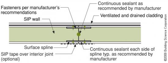
      Figure 7. A surface spline reduces thermal bridging much more than a structural spline at SIP panel seams.

      An insulated spline is another option for avoiding thermal bridging at SIP panel seams.
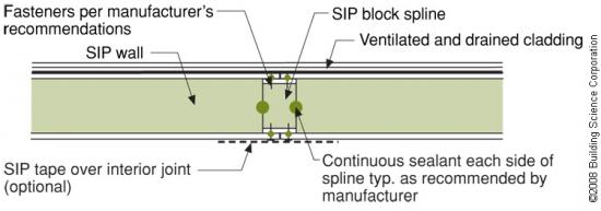
      Figure 8. An insulated spline is another option for avoiding thermal bridging at SIP panel seams.

      A structural spline made of a solid 2x is used where needed to meet structural load requirements at SIP panel seams.
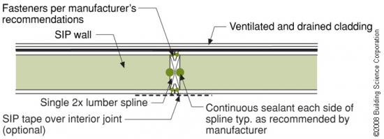
      Figure 9. A structural spline made of a solid 2x is used where needed to meet structural load requirements at SIP panel seams.


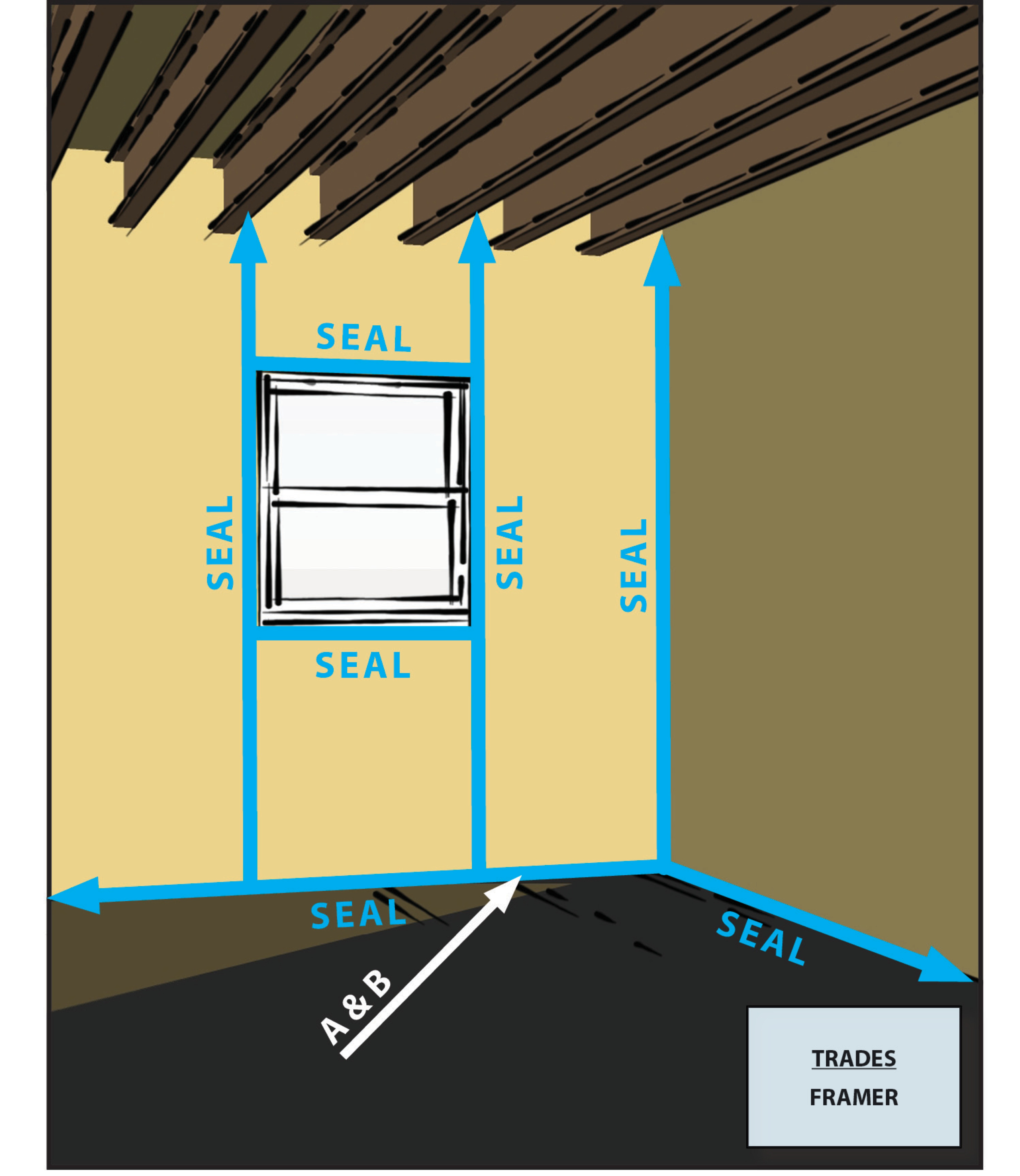
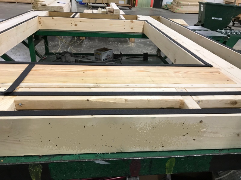
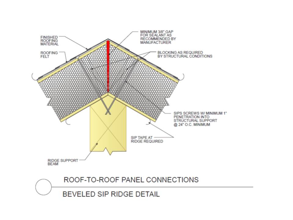
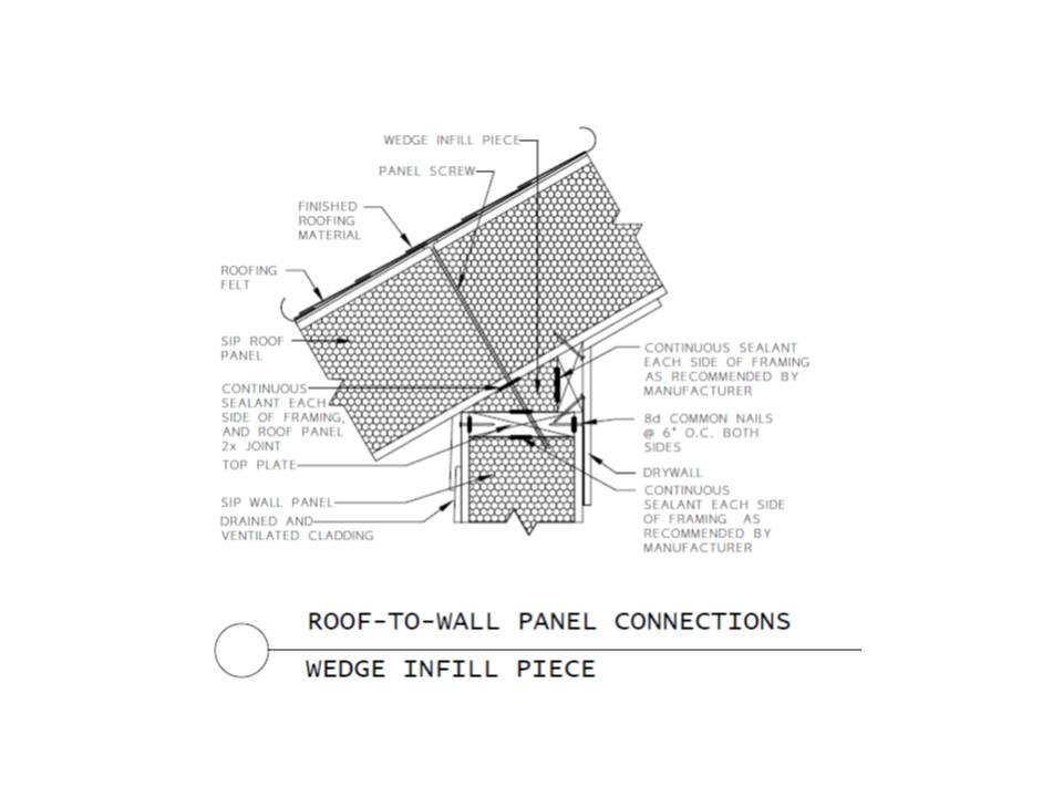
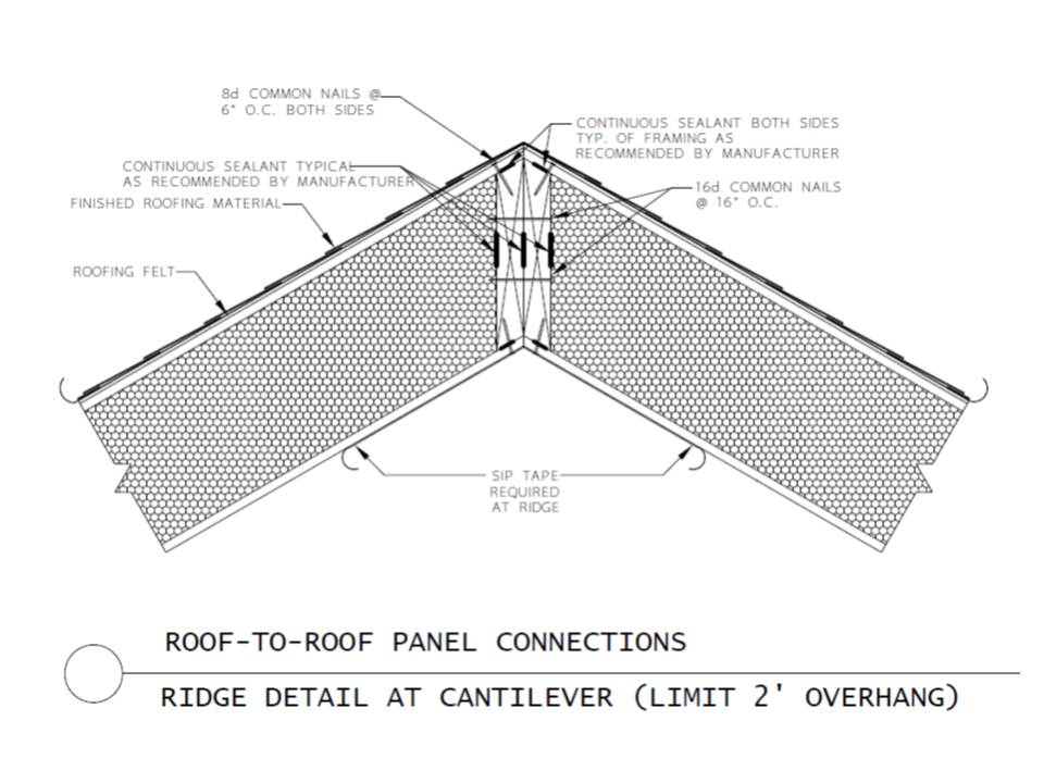
      Apply caulk to the seams before assembly following the SIP manufacturer’s instructions and using their caulk, if provided. Make sure seams are continuous (see Figure 10). Consider using a power caulker. The wall/floor, wall/wall, and wall/roof seams can each require as many as six beads of caulk, and the roof ridge can require up to 8 beads of caulk. In a 1200-square-foot house this can total over 5,000 linear feet of caulk (more than 17 football fields).

      Use lift plates and a belt winch (available from the manufacturer) to pull panels together tightly, if needed (Figure 11).

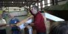
      Install peel-and-stick tape at panel-to-panel seams and at the ridge and wall-roof interface (See Figure 12).

      Use a smoke pencil and blower door testing prior to drywalling to ensure that panel seams are tight (Figure 13).
       
      Make sure the beads of caulk are continuous the full length at each SIP panel seam, such as at the wall-roof seam, to maintain air barrier continuity.
      Figure 10. Make sure the beads of caulk are continuous the full length at each SIP panel seam, such as at the wall-roof seam, to maintain air barrier continuity.

      Lifting plates attached to the wall provide good bracing to tighten up SIP panel seams
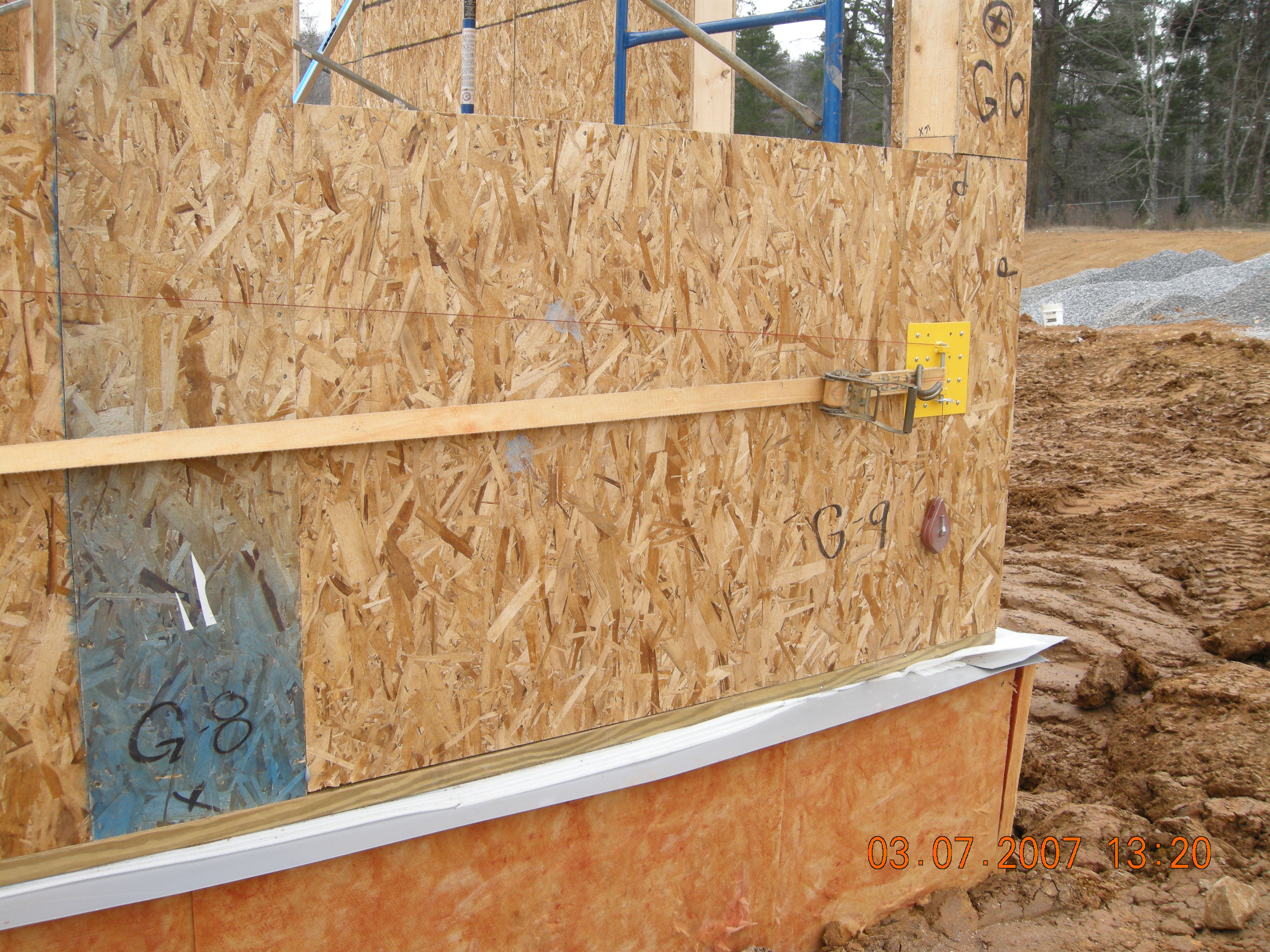
      Figure 11. Lifting plates attached to the wall provide good bracing to tighten up SIP panel seams (Source: ORNL).
       
      Peel-and-stick panel tape provides added assurance that SIP panel seams will remain airtight
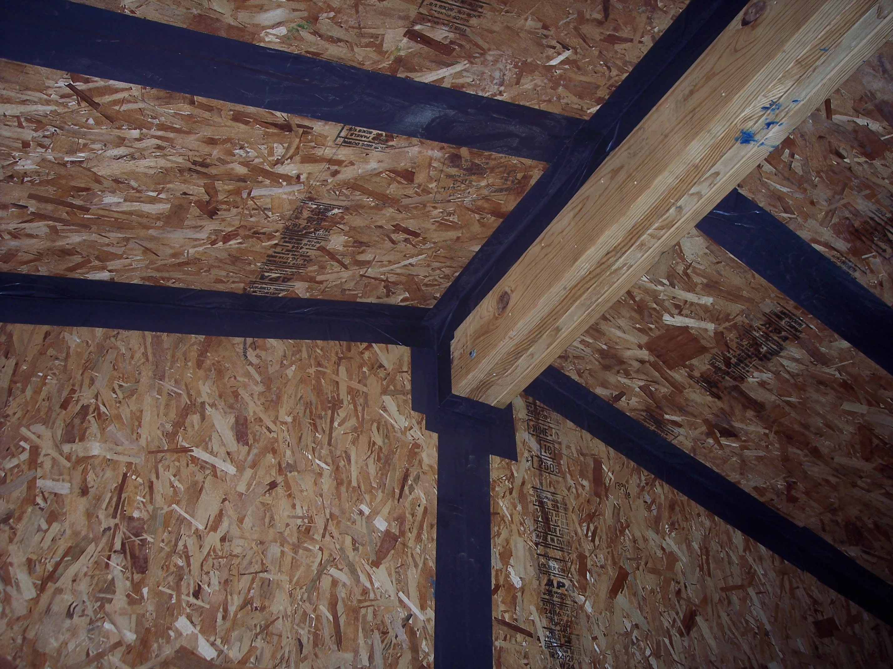
      Figure 12. Peel-and-stick panel tape provides added assurance that SIP panel seams will remain airtight (Source: ORNL).
       
      Use a smoke pencil to check for air leaks at SIP panel seams, especially along the ridge beam
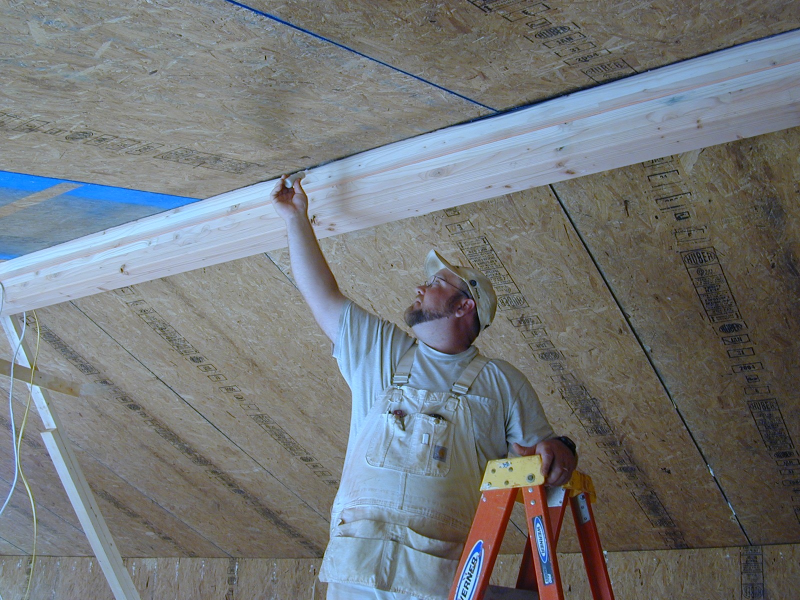
      Figure 13. Use a smoke pencil to check for air leaks at SIP panel seams, especially along the ridge beam (Source: ORNL).
    6. Cut panels for window and door rough openings.
      In pre-manufactured SIP kits, the rough openings for windows and doors are all pre-cut and routed. However, if the raw panels are used, these openings will need to be made on site. First, mark the rough opening on the SIP. The rough opening can be in one or two panels. If the width is greater than 5 ft., the load at the header should be engineered (box beam, insulated header, or built-up structural header). The opening is easily cut with a light-weight chainsaw with a stable base plate. Once the panel sections are knocked out, remove foam from all four sides to a depth of 1.5 in. with a hot wire scoop. Apply a bead of caulk to the inside surface of both faces all the way around the opening and apply a bead of expanding foam to the foam core. Install the 2X sill cut to 3 inches longer than the rough opening width. Then install the same length header. Hammer in the side jambs, which are cut to the rough opening height. Nail off all the 2x opening frames from both facings every 6 in. (Morley 2000).
    7. Install electrical wiring.
      Electrical wiring placement should be designed to stay as much as possible within interior walls. Electric chases are cut in the SIP foam prior to shipping, and when the panels are installed you must provide 1.5-in.-diameter access holes in plating, structural splines, and the precast foundation to align with electrical wire chases in the panels. From the basement or crawlspace, the electrician can easily measure the location of each vertical wire chase. All electrical wires are pulled after cutting out the outlet box locations and prior to setting the electric boxes. The boxes are threaded onto the wires and set in the SIP. Apply low-expanding foam sealant around the box and in the chase once all the wires are pulled to block this potential air leakage path. The wall detail in Figure 14 is one technique for installing electrical wiring without having to cut into SIP panels.

      When positioning ceiling fans and other heavy lighting fixtures, be sure the locations are clearly dimensioned on the drawings sent to the SIP manufacturer so the manufacturer can provide added structural support and electric chases in the SIP ceiling panels. With a little planning, the desired location of these fixtures can be aligned with the panel splines and additional solid wood inserted in the panels in the factory. Along the ridge beam is also a good location to include a wire chase (Christian 2010).
      This technique for installing electrical wiring avoids the need to cut into the SIP panel.
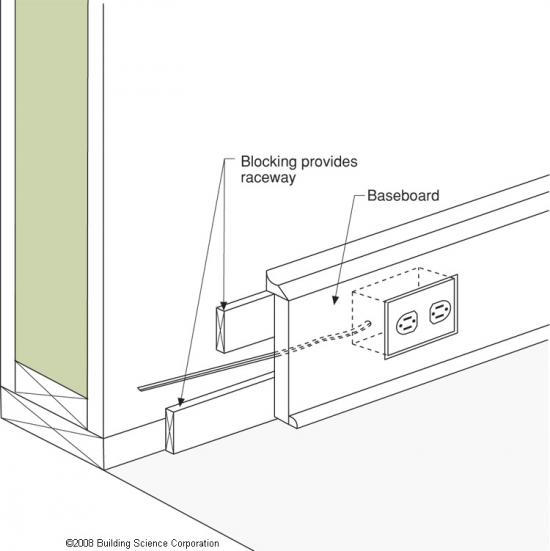
      Figure 14. This technique for installing electrical wiring avoids the need to cut into the SIP panel.
    8. Install plumbing.
      Keep plumbing out of exterior walls. More pipe hangers may be needed to suspend water and sewer piping below a SIP floor.
    9. Install a drainage plane.
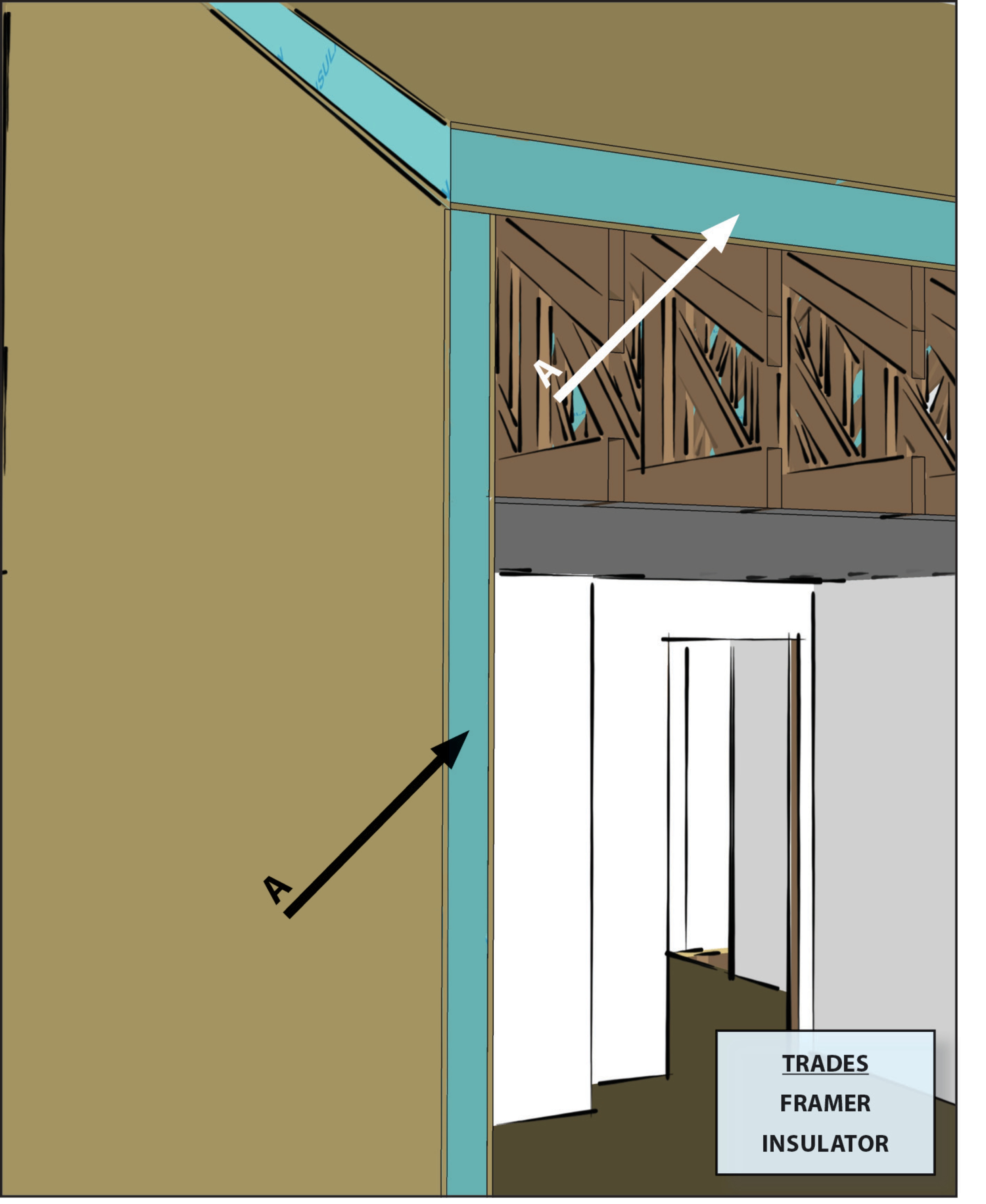
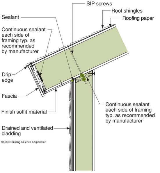
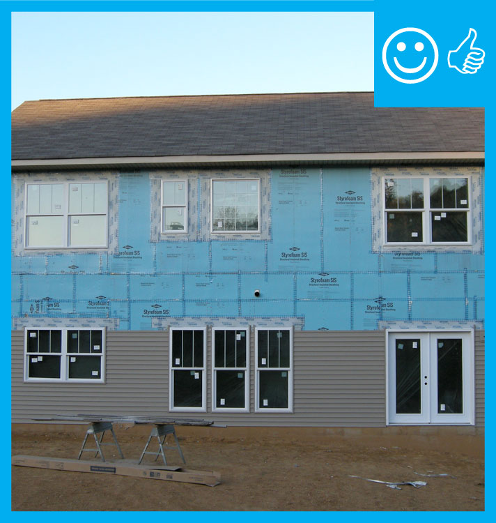
      The above-grade wall drainage plane can be attained by wrapping the house with one or two layers of house wrap and making sure the window/SIP interface is correct (Figures 15 and 16). Install sill pans under each window and door that drain only to the outside (Figure 17). The drainage plane must be continued at the base of the first floor by providing flashing that directs any wind-driven rainwater away from the wall at the wall-foundation junction. Figure 18 shows the detailing of the drainage plane at an exterior corner (BSC 2008).
       
      Two layers of high-permeability house wrap are installed to provide a drainage layer between the SIPS and the homes external cladding.
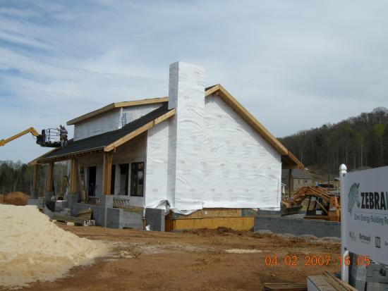
      Figure 15. Two layers of high-permeability house wrap are installed to provide a drainage layer between the SIPS and the homes external cladding.

      After installing the house wrap over the SIPS, window flashing is installed.
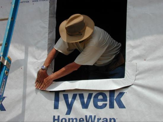
      Figure 16. After installing the house wrap over the SIPS, window flashing is installed (Source: BSC 2009).
       
      The back dam of the window sill will force water out.
      Figure 17. The back dam of the window sill will force water out.
       
      Install a housewrap drainage plane between the SIP panels and the exterior cladding.
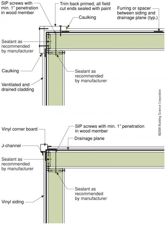
      Figure 18. Install a housewrap drainage plane between the SIP panels and the exterior cladding.
    10. Install exterior cladding and interior finishes.
      Exterior siding or masonry veneer can be applied to a SIP similarly to stud-constructed walls. Because fasteners will be embedded in the 7/16-inch OSB sheathing only, review the cladding manufacturer's attachment requirements and the OSB fastener withdrawal strengths. Some SIP manufacturers recommend using 8d ring shank nails  and placing 25% more fasteners than the siding manufacturer would recommend for stick framing (for example nails placed every 12 inches instead of every 16 inches) or using screws instead of nails or staples at same fastener schedule (Premier SIPS 2011). In some high wind areas, horizontal lapped siding may require both blind and face nailing on prescribed spacing for proper attachment to SIPs.
      SIPs walls and ceilings are usually covered with drywall on the interior. Applying drywall on SIP panels is easier than applying to studs because the solid OSB backing allows fasteners to be applied and drywall joints can occur almost anywhere, reducing drywall waste. Vertical drywall seams should be offset from structural insulated panel seams. Because SIP panels are straighter, no shimming is required.
    11. Attaching roof cladding and solar modules to SIPs
      The recommended roofing to cover a SIP roof structure and attach solar collectors is raised metal seam roofing. The standing seams on the roof allows for the attachment of the solar water heater collectors and photovoltaic modules without any roof penetrations. This is advantageous because fewer roof membrane penetrations mean less water leak risk.
    Success
    Ensuring Success

    The air tightness of the envelope assembly can be easily tested by conducting a whole-house blower test prior to drywall installation. While the house is depressurized, inspect all panel seams with a smoke stick. This test will help identify uncontrolled air passages during construction when it is much easier to seal from the inside space instead of the enclosed attic and crawl space. Other steps the builder can take to ensure success in reducing thermal bridging with SIP construction include planning ahead to simplify the design, taking care with the design to use a single ridge beam; minimize the number of seams; plan for electrical, plumbing and HVAC routes to minimize cuts in the SIPS; use trained installers, use a square and level foundation; keep panels clean, dry, and flat prior to installation; careful air and water management at windows and doors; and careful caulking and sealing at all panel seams.

    Climate
    Climate

    Since the typical 4.5 inch thick SIP with OSB sandwiching EPS type I insulation is uniformly vapor semi-impermeable and “bi-laterally” symmetrical – the resistance to vapor flow is identical from one side of the panel centerline to the next. This means that if the SIP core is at least 3.5 inches thick and if the core has a vapor resistance of 3.5 perms or less per inch, then this wall assembly can be used in any climate zone. (Lstiburek 2008). In very cold climates, including the Arctic and Antarctic, special air sealing techniques are required, see the Builders Guide to Structural Insulated Panels (SIPs) for all Climates for guidance. 

    Earthquake-Prone Areas

    In areas that are prone to earthquakes the structure should be built with the appropriate seismic protection. The IRC authorizes SIP construction in Seismic Design Categories A, B, and C, but SIPs can also be utilized in higher-risk seismic zones when code compliance can be demonstrated through a recognized third-party evaluation report. Construction in higher-risk seismic zones may require additional engineering.

    Probabilistic map of the expected number of damaging earthquakes around the United States, in a 10,000-year span.
    Figure 1. Probabilistic map of the expected number of damaging earthquakes around the United States, in a 10,000-year span (Source: USGS 2014).


    Training
    Right and Wrong Images
    Image
    Right – This home’s roof and walls are constructed of SIP panels; metal studs provide fastening surfaces across the long expanses of ceiling in the open interiors.
    Right – This home’s roof and walls are constructed of SIP panels; metal studs provide fastening surfaces across the long expanses of ceiling in the open interiors.
    Image
    Right – Graphite enhanced EPS fills these SIP panels, providing additional insulation value.
    Right – Graphite enhanced EPS fills these SIP panels, providing additional insulation value.
    Image
    Right – Structural insulated panels are quickly assembled on site for this SIP house.
    Right – Structural insulated panels are quickly assembled on site for this SIP house.
    Image
    Right – Strips of SIP panels are used to sheath and insulate the rim joists.
    Right – Strips of SIP panels are used to sheath and insulate the rim joists.
    Image
    Right – A double bead of sealant seals the seams between the SIP panel and spline.
    Right – A double bead of sealant seals the seams between the SIP panel and spline.
    Image
    Right – Structural insulated sheathing can provide racking strength (lateral load resistance), and serve as an air barrier and thermal barrier if installed according to manufacturer’s specifications with taped, sealed seams
    Right – Structural insulated sheathing can provide racking strength (lateral load resistance), and serve as an air barrier and thermal barrier if installed according to manufacturer’s specifications with taped, sealed seams
    Image
    Right – Verify SIP headers are installed
    Right – Verify SIP headers are installed
    Image
    Right – Tape seals the SIP panel seams.
    Right – Tape seals the SIP panel seams.
    Image
    Right – An insulated spline reduces heat transfer at the SIP panel joints.
    Right – An insulated spline reduces heat transfer at the SIP panel joints.
    Image
    All seams between structural insulated panels (SIPs) foamed and/or taped per manufacturer's instructions
    All seams between structural insulated panels (SIPs) foamed and/or taped per manufacturer's instructions
    Image
    Because all of the structural load is carried by the SIP roof and wall panels, no trusses are needed, allowing the home to have vaulted ceilings and open interiors throughout.
    Because all of the structural load is carried by the SIP roof and wall panels, no trusses are needed, allowing the home to have vaulted ceilings and open interiors throughout.
    Image
    Joints between SIP panels can be connected with solid lumber splines or SIP panel pieces. SIP panel pieces help to ensure a continuous layer of insulation across the building shell.
    Joints between SIP panels can be connected with solid lumber splines or SIP panel pieces. SIP panel pieces help to ensure a continuous layer of insulation across the building shell.
    Image
    SIP homes built in coastal locations should be constructed so that the lowest level is well above the BFE.
    SIP homes built in coastal locations should be constructed so that the lowest level is well above the BFE.
    Image
    Structural insulated panels provide a continuous layer of insulation sandwiched between two continuous layers of OSB for thermal protection and sturdy construction.
    Structural insulated panels provide a continuous layer of insulation sandwiched between two continuous layers of OSB for thermal protection and sturdy construction.
    Image
    SIP panel walls are less susceptible to air leakage and convection issues than stick-built walls
    SIP panel walls are less susceptible to air leakage and convection issues than stick-built walls
    Image
    Right – This home’s roof and walls are constructed of SIP panels; metal studs provide fastening surfaces across the long expanses of ceiling in the open interiors.
    Right – This home’s roof and walls are constructed of SIP panels; metal studs provide fastening surfaces across the long expanses of ceiling in the open interiors.
    Image
    Right – Graphite enhanced EPS fills these SIP panels, providing additional insulation value.
    Right – Graphite enhanced EPS fills these SIP panels, providing additional insulation value.
    Image
    Right – This modular home consists of prebuilt wall panels that are assembled on site.
    Right – This modular home consists of prebuilt wall panels that are assembled on site.
    Image
    Right – Foam gasket is installed on the surface of the framing before plywood sheathing is installed on these factory-constructed wall panels.
    Right – Foam gasket is installed on the surface of the framing before plywood sheathing is installed on these factory-constructed wall panels.
    Image
    Right – Sheathing, rigid foam, and windows are installed in the factory for these factory-constructed wall panels.
    Right – Sheathing, rigid foam, and windows are installed in the factory for these factory-constructed wall panels.
    Image
    Right – Structural insulated panels are quickly assembled on site for this SIP house.
    Right – Structural insulated panels are quickly assembled on site for this SIP house.
    Image
    Right – Prepoured foundation panels with integrated insulation and vapor barrier are installed in place.
    Right – Prepoured foundation panels with integrated insulation and vapor barrier are installed in place.
    Image
    Right – The foundation wall consists of prefab concrete wall panels with integrated insulation.
    Right – The foundation wall consists of prefab concrete wall panels with integrated insulation.
    Image
    Right – Insulated concrete forms (ICFs) provide the insulated stem wall for the slab-on-grade foundation for this SIP house.
    Right – Insulated concrete forms (ICFs) provide the insulated stem wall for the slab-on-grade foundation for this SIP house.
    Image
    Right – SIP panels assemble quickly on site to provide sturdy walls and a roof that needs few interior supports so there is great flexibility in the layout of interior spaces.
    Right – SIP panels assemble quickly on site to provide sturdy walls and a roof that needs few interior supports so there is great flexibility in the layout of interior spaces.
    Videos
    Publication Date
    Author(s)
    Cold Climate Housing Research Center
    Organization(s)
    CCHRC
    Description
    Video from Cold Climate Housing Research Center on SIP construction and how to build with these materials.
    CAD
    CAD Files
    Connection of two SIP wall panels at a corner
    Connection of two SIP wall panels at a corner
    Download: DWG PDF
    Connection of a concrete foundation wall to SIP wall panel with a sill plate and floor joist
    Connection of a concrete foundation wall to SIP wall panel with a sill plate and floor joist
    Download: DWG PDF
    Connection of a SIP roof panel to a SIP roof panel with a foam ridge cap
    Connection of a SIP roof panel to a SIP roof panel with a foam ridge cap
    Download: DWG PDF
    Connection of two SIP roof panels with beveled edges at roof ridge
    Connection of two SIP roof panels with beveled edges at roof ridge
    Download: DWG PDF
    Connection of a SIP roof panel to a beveled SIP wall panel
    Connection of a SIP roof panel to a beveled SIP wall panel
    Download: DWG PDF
    Connection of the first floor and second floor wall panels with a hanging floor
    Connection of the first floor and second floor wall panels with a hanging floor
    Download: DWG PDF
    SIP roof panel detailing at eaves with an angled fascia
    SIP roof panel detailing at eaves with an angled fascia
    Download: DWG PDF
    Connection of roof truss to wall panel
    Connection of roof truss to wall panel
    Download: DWG PDF
    Connection of concrete foundation to SIP wall panel
    Connection of concrete foundation to SIP wall panel
    Download: DWG PDF
    Connection of foundation wall to rim joist to SIP wall panel
    Connection of foundation wall to rim joist to SIP wall panel
    Download: DWG PDF
    Connection of a SIP roof panel to a SIP wall panel with a wedge infill piece
    Connection of a SIP roof panel to a SIP wall panel with a wedge infill piece
    Download: DWG PDF
    Connection of two SIP roof panels with beveled edges at roof ridge with support for roof cantilever overhang
    Connection of two SIP roof panels with beveled edges at roof ridge with support for roof cantilever overhang
    Download: DWG PDF
    Connection of first and second floor SIP wall panels with a floor joist in between
    Connection of first and second floor SIP wall panels with a floor joist in between
    Download: DWG PDF
    SIP roof panel detailing at the eaves with a vertical fascia and soffit board
    SIP roof panel detailing at the eaves with a vertical fascia and soffit board
    Download: DWG PDF
    SIP roof panel detailing at the eaves with a framed overhang, a vertical fascia and soffit board
    SIP roof panel detailing at the eaves with a framed overhang, a vertical fascia and soffit board
    Download: DWG PDF
    SIP roof panel detailing at the eaves with a short overhang, a vertical fascia and soffit board
    SIP roof panel detailing at the eaves with a short overhang, a vertical fascia and soffit board
    Download: DWG PDF
    SIP roof panel detailing at the eaves with an angled fascia and soffit board
    SIP roof panel detailing at the eaves with an angled fascia and soffit board
    Download: DWG PDF
    Connection of SIP wall panels with dimensional lumber splines
    Connection of SIP wall panels with dimensional lumber splines
    Download: DWG PDF
    SIP panel door and wall framing
    SIP panel door and wall framing
    Download: DWG PDF
    Connection of SIP wall panels with block splines
    Connection of SIP wall panels with block splines
    Download: DWG PDF
    Compliance

    Compliance

    The Compliance tab contains both program and code information. Code language is excerpted and summarized below. For exact code language, refer to the applicable code, which may require purchase from the publisher. While we continually update our database, links may have changed since posting. Please contact our webmaster if you find broken links.

    ENERGY STAR Single-Family New Homes, Version 3/3.1 (Rev. 11)

    Thermal Enclosure System. 
    3. Reduced Thermal Bridging. 
    3.4 At above-grade walls separating conditioned from unconditioned space, one of the following options used (rim / band joists exempted):17
    3.4.2 Structural Insulated Panels OR; Insulated Concrete Forms OR; Double-wall framing OR;18, 21

    Footnote 17) Mass walls utilized as the thermal mass component of a passive solar design (e.g., a Trombe wall) are exempt from this Item. To be eligible for this exemption, the passive solar design shall be comprised of the following five components: an aperture or collector, an absorber, thermal mass, a distribution system, and a control system. For more information, see: https://www.energy.gov/sites/prod/files/guide_to_passive_solar_home_design.pdf. Mass walls that are not part of a passive solar design (e.g., CMU block or log home enclosure) shall either utilize the strategies outlined in Item 3.4 or the pathway in the assembly with the least thermal resistance, as determined using a method consistent with the 2013 ASHRAE Handbook of Fundamentals, shall provide ≥ 50% of the applicable assembly resistance, defined as the reciprocal of the mass wall equivalent U-factor in the 2009 IECC Table 402.1.3. Documentation identifying the pathway with the least thermal resistance and its resistance value shall be collected by the Rater and any Builder Verified or Rater Verified box under Item 3.4 shall be checked.

    Footnote 18) Up to 10% of the total exterior wall surface area is exempted from the reduced thermal bridging requirements to accommodate intentional designed details (e.g., architectural details such as thermal fins, wing walls, or masonry fireplaces; structural details, such as steel columns). It shall be apparent to the Rater that the exempted areas are intentional designed details or the exempted area shall be documented in a plan provided by the builder, architect, or engineer. The Rater need not evaluate the necessity of the designed detail to certify the home.

    Footnote 21) Double-wall framing is defined as any framing method that ensures a continuous layer of insulation covering the studs to at least the R-value required in Item 3.4.1 of the Checklist, such as offset double-stud walls, aligned double-stud walls with continuous insulation between the adjacent stud faces, or single-stud walls with 2x2 or 2x3 cross-framing. In all cases, insulation shall fill the entire wall cavity from the interior to exterior sheathing except at windows, doors and other penetrations.

    Please see the ENERGY STAR Single-Family New Homes Implementation Timeline for the program version and revision currently applicable in in your state.

    DOE Zero Energy Ready Home (Revision 07)

    Exhibit 1 Mandatory Requirements.
    Exhibit 1, Item 1) Certified under the ENERGY STAR Qualified Homes Program or the ENERGY STAR Multifamily New Construction Program.
    Exhibit 2, Item 2) Ceiling, wall, floor, and slab insulation shall meet or exceed 2015 IECC levels and achieve Grade 1 installation, per RESNET standards.


    2009, 2012, 20152018, and 2021 International Residential Code (IRC)

    Section R301.2.2 outlines the seismic provisions and requirements for townhouses in Seismic Design Categories C, D0, D1, and D2 and detached one- and two-family dwellings in Seismic Design Categories D0, D1, and D2. Seismic design categories are determined based on spectral response acceleration, SDS, which depends on location and soil conditions. Buildings in Seismic Design Category E shall be designed to resist seismic loads in accordance with the International Building Code, although Section R301.2.2 discusses methods for reclassifying to a lower seismic design category.

    Section R301.2.2.2.1 limits the dead load weight for above grade SIP walls to ten pounds per square foot (480 Pa).

    Section R301.2.2.7 (2009, 2012, 2015 IRC R301.2.2.3.1) limits the height of structural insulated panel buildings to two stories above grade plane.  

    R301.3 limits the story height of SIP walls to no more than 11 feet 7 inches (3531 mm) and bearing wall height per story as permitted by Section R610 tables not to exceed 10 feet (3048 mm). 2009 IRC limits maximum floor framing height to no more than 16 inches (406 mm).

    Section R602.1.11 (2018 IRC R610.3) Structural insulated panels shall be manufactured and identified in accordance with ANSI/APA PRS 610.1. 2009-2015 IRC do not specify ANSI/APA PRS 610.1 but specify materials required for SIPs in Section R610 (2015 IRC Section R610, 2012 IRC Section R613, and 2009 IRC Section 614)

    Section R610 (2012 IRC Section R613 and 2009 IRC Section 614) outlines additional requirements for SIP system construction. The provisions of this section are limited to SIP constructed buildings that are no greater than 60 feet (18288 mm) in length perpendicular to the joist or truss span, no greater than 40 feet (12192 mm) in width parallel to the joist or truss span and no greater than two stories in height with each wall no greater than 10 feet (3048 mm) high. In addition, ultimate design wind speed (Vult) should not be greater than 155 miles per hour (69 m/s) in Exposure B or 140 miles per hour (63 m/s) in Exposure C, ground snow load is no greater than 70 pounds per square foot (3.35 kPa), and the seismic design category is A, B, or C.

    Retrofit:  2009, 2012, 2015, 2018,  and 2021 IRC

    Section R102.7.1 Additions, alterations, or repairs. Additions, alterations, renovations, or repairs shall conform to the provisions of this code, without requiring the unaltered portions of the existing building to comply with the requirements of this code, unless otherwise stated. (See code for additional requirements and exceptions.)

    Appendix J regulates the repair, renovation, alteration, and reconstruction of existing buildings and is intended to encourage their continued safe use.


    More

    More Info.

    Access to some references may require purchase from the publisher. While we continually update our database, links may have changed since posting. Please contact our webmaster if you find broken links.

    References and Resources*
    Author(s)
    U.S. Environmental Protection Agency
    Organization(s)
    EPA
    Publication Date
    Description
    Guide describing details that serve as a visual reference for each of the line items in the Thermal Enclosure System Rater Checklist.
    Author(s)
    California Energy Commission,
    Enermodal Engineering Limited
    Organization(s)
    CEC,
    EEL
    Publication Date
    Description
    Document with information from a workshop addressing framing materials for residential buildings in California. A copy of the document can be requested at the resource link, and an online copy of the document can be found by searching for it on the California Energy Commission's Library Online...
    Author(s)
    Carpenter Stephen C,
    Schumacher Christopher
    Organization(s)
    American Society of Heating Refrigerating and Air-Conditioning Engineers,
    ASHRAE
    Publication Date
    Description
    Case study characterizing the framing factors for the exterior walls, ceilings, and floors of 180 wood-framed low-rise residential buildings across the United States.
    Author(s)
    Christian Jeffrey E,
    Bonar Jacob
    Organization(s)
    Oak Ridge National Laboratory
    Publication Date
    Description
    Presentation about building highly efficient, affordable homes that will achieve 40% whole-house energy savings in mixed-humid climates.
    Author(s)
    Christian Jeffrey E,
    Childs Phillip W,
    Pate Paige,
    Atchley Jerald A
    Organization(s)
    American Society of Heating Refrigerating and Air-Conditioning Engineers,
    ASHRAE
    Publication Date
    Description
    Paper describing the development and testing of an affordable net-zero energy house in Lenoir City, Tennessee.
    Author(s)
    Christian Jeffrey E,
    Beal David,
    Kerrigan Philip
    Organization(s)
    Oak Ridge National Laboratory,
    ORNL,
    Florida Solar Energy Center,
    FSEC,
    Building Science Corporation,
    BSC
    Publication Date
    Description
    Paper describing testing for the first of a series of six near net-zero-energy test houses, using the results to work towards the construction of a true net-zero-energy house.
    Author(s)
    Christian Jeffrey E
    Organization(s)
    American Society of Heating Refrigerating and Air-Conditioning Engineers,
    ASHRAE
    Publication Date
    Description
    Case study about affordable housing in a mixed, humid climate.
    Author(s)
    Christian Jeffrey E
    Organization(s)
    Oak Ridge National Laboratory,
    ORNL
    Publication Date
    Description
    Report presenting construction methods, building products, appliances and equipment of four single-family houses that achieve dramatic energy reductions and approach “net zero energy” use.
    Author(s)
    Morley Michael
    Organization(s)
    Taunton Press
    Publication Date
    Description
    An online learning management resource for the construction community.
    Author(s)
    Premier SIPS
    Organization(s)
    Premier SIPS
    Publication Date
    Description
    Information sheet with nail withdrawl capacities in OSB.
    Author(s)
    Structural Insulated Panel Association
    Organization(s)
    Structural Insulated Panel Association
    Author(s)
    Federal Emergency Management Agency
    Organization(s)
    FEMA
    Publication Date
    Description
    Fact sheet providing guidance on alternative building materials and techniques and their application in coastal environments, and discussing Engineered Wood Products, Structural Insulated Panels, Insulating Concrete Forms, Prefabricated Shear Walls and Moment Frames, Sprayed Closed-Cell Foam...
    Author(s)
    Structural Insulated Panel Association
    Organization(s)
    SIPA
    Publication Date
    Description
    Guide informing builders and developers about efficient building practice for constructing homes with structural insulated panels.
    Author(s)
    Structural Insulated Panel Association
    Organization(s)
    SIPA
    Publication Date
    Description
    Guide informing architects and engineers about designing buildings to be constructed with structural insulated panels.
    *For non-dated media, such as websites, the date listed is the date accessed.
    Contributors to this Guide

    The following authors and organizations contributed to the content in this Guide.

    Sales
    Building Science Measures
    Building Science-to-Sales Translator

    Structural Insulated Panels (SIPs) = SIP Thermal Blanket

    Image(s)
    Technical Description

    Structural insulated panels (SIPs) are a sandwich made up of foam insulation glued between two layers of sheathing (e.g., oriented strand board, magnesium oxide board, or drywall). SIP wall and roof panels are produced in a factory and come to the job site clean, dry, straight, and precisely made to the wall dimensions specified in the house plans with precut openings for doors and windows. They assemble quickly, producing a sturdy, well-sealed, well-insulated structure. Because there is minimal to no framing, the foam core provides a nearly continuous thermal blanket around the entire structure so heat transfer through the framing is greatly reduced.

    SIP Thermal Blanket
    Sales Message

    SIP thermal blanket construction blocks excessive heat loss and gain though structural framing. What this means to you is less wasted energy along with enhanced comfort and quiet. Knowing there is one opportunity during construction to lock in quality construction, wouldn’t you agree advanced thermal protection is a great investment?

    Last Updated

    Did you find this information helpful?

    If you have questions and/or would like a reply to this feedback, please include your e-mail address in the message.
    This question is for testing whether or not you are a human visitor and to prevent automated spam submissions.