


Drawings
2021 IECC Climate Zone 1A: Unvented Attic, 2x6 Wall, Monolithic Slab
Notes
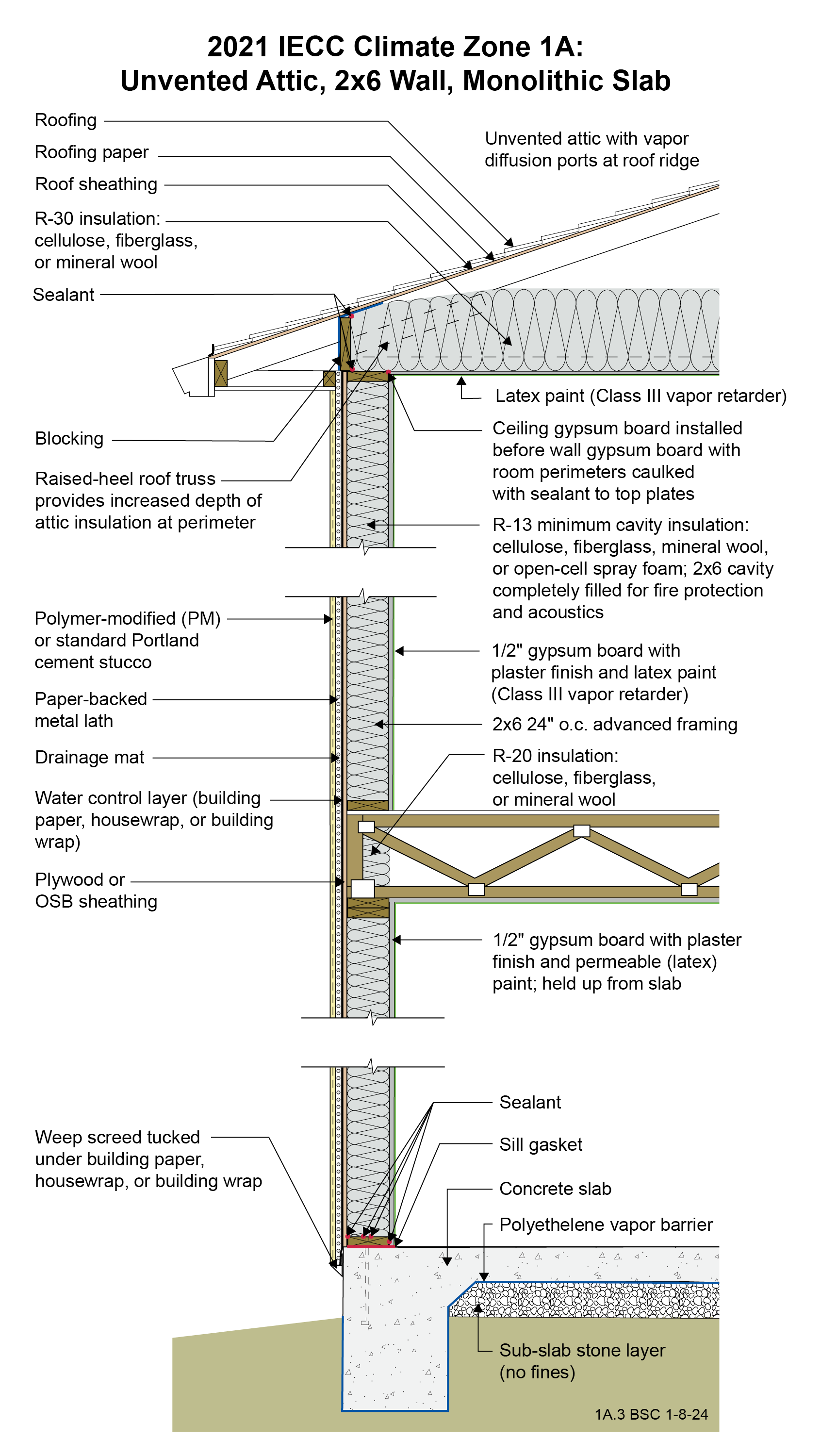
Drawing 1A.3: IECC CZ 1A: Unvented Attic, 2x6 Wall, Monolithic Slab
- The attic insulation in this unvented attic is located on the attic floor. The moisture in the attic space is controlled by vapor diffusion ports, not with attic venting. Unvented attics are more resistant to wind uplift under hurricane conditions.
- A drainage mat is provided behind the stucco layer installed over the frame wall to control hydrostatic pressure. This assembly is drained to the exterior at a weep screed located at the bottom of the wood framing. The stucco layer should not be extended into the ground in order to control wicking and insect entry.
- The wall is framed with 2x6 24” o.c. advanced framing as it uses less board footage (volume of wood framing) than standard 2x4 16” o.c. framing and has therefore been shown to be less expensive in material cost. It has also been proven to be less expensive in labor (25% fewer framing members) and is faster to assemble. Although the code allows for 2x4 framing and lower R-value cavity insulation the use of advanced framing and the associated cost savings can more than offset the increase in the cost of cavity insulation (this of course depends on relative price fluctuations in labor and materials).
- Although the minimum R-value of the insulation in this wall is R-13 per IECC, fire code may require the entire cavity to be filled, likely resulting in a higher R-value for a 2x6 wall.
- Avoid vinyl wallpaper and oil-based paint or coatings in Climate Zone 1A. These wall coverings are vapor impermeable and increase the risk of condensation within the wall.
- The entire monolithic concrete slab should have a polyethylene vapor barrier wrapping the underside of the thickened slab edge to control capillary uptake. The polyethylene should extend upward from the bottom of the monolithic slab to grade on the exterior.
2021 IECC Window Detail: Framed Wall with Plywood or OSB Sheathing, a WRB, and Siding (Wood, Fiber Cement, Aluminum or Vinyl, or Stucco)
Notes
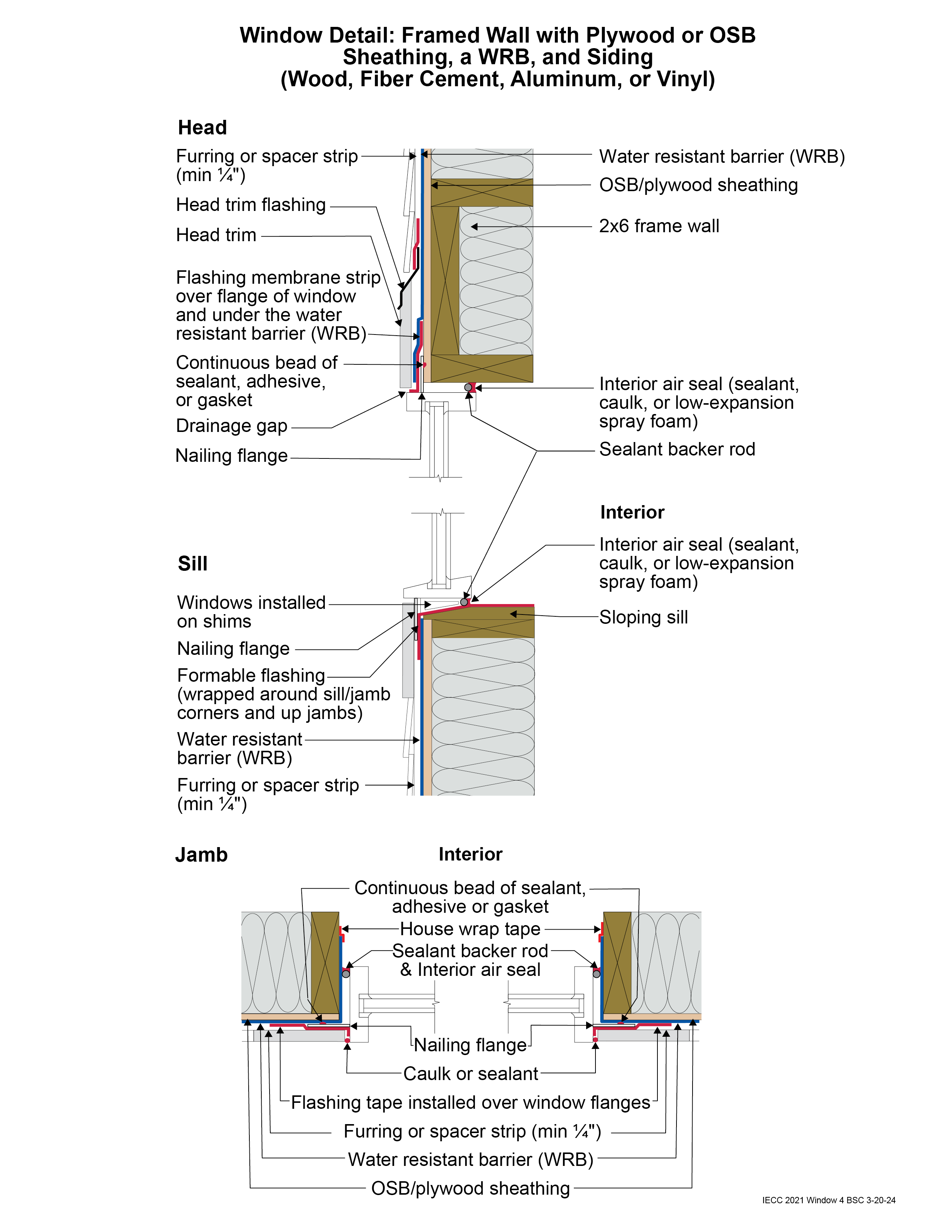
Window Detail 4 - Framed Wall with Plywood or OSB Sheathing, a WRB, and Siding (Wood, Fiber Cement, Aluminum or Vinyl, or Stucco)
- Note: Always follow the window manufacturer’s installation guidance. Not following manufacturer guidance may void the warranty.
- This is a “drained wall”. Drainage occurs between the siding and the water control layer or water resistant barrier (WRB) in the gap created by furring which is installed vertically over the water control layer (WRB) at stud locations. In the case of a stucco wall, the drainage plane is a drainage mat rather than furring gaps.
- The window openings are drained to the water control layer (WRB).
- The rough opening at the window sill is sloped and flashed with a formable flashing.
- The upper portion of the head trim flashing goes under the furring and is taped directly to the WRB with flashing tape. The furring is “cut through” by the head trim flashing, so that the furring below the flashing (behind the head trim) is separate from the furring above the flashing (behind the siding). During construction, the head trim is installed first on short strips of furring. It is flashed directly to the WRB as described above. The rest of the furring is installed with the siding. In the case of a stucco wall, the drainage mat would be treated in similar fashion to furring: the head trim flashing would go under the drainage mat and be taped directly to the WRB with flashing tape.
- Note the gap between the head trim and the top of the window assembly frame. This gap allows water to drain and allows the bottom of the trim to dry out more easily. If installed without this gap, capillary action can draw water into the tight space between the head trim and the window assembly frame. Note also the gap between the siding and the head trim flashing, which serves the same purposes.
- Consider installing rigid head flashing (rigid head flashing is not shown in the schematic). Rigid head flashing is similar to the head trim flashing shown in the schematic, but it goes over the top of the window frame instead of over the head trim. This is required by some manufacturers. It should be installed against the head nailing flange and over the top of the window frame. The vertical and horizontal portion of the flashing should be sealed directly to the window frame and flange with sealant. The red flashing membrane strip shown overlapping the head nailing flange in the schematic would now overlap the rigid head flashing. Use rigid head flashing with a drip edge to guide water away from the window assembly.
- Backer rod for the interior air sealant should be installed after the window is installed, leveled, and shimmed. Use the correct size backer rod.


