

Scope
Retrofit an existing flat roof to improve thermal, water, and air control performance as follows:
- Remove the existing roofing membrane and inspect the roof for any deficiencies.
- Make the necessary corrections to the roof framing and decking prior to beginning the new work.
- Air seal wall cavities made accessible by roof demolition and install insulation in the roof cavity.
- Provide a continuous air control layer within the roof assembly. Ensure the roof assembly air control layer is connected to the wall (and other roof elements) air control layer.
- Install polyisocyanurate rigid foam insulation over the air control layer. Ensure that the ratio of rigid foam (“air impermeable insulation”) to cavity insulation (“air permeable insulation” meets the code requirements to avoid condensation.
- Install insulation cover board and roofing membrane with flashing as the water control layer.
- Flash around all roof penetrations, including blocking added for PV racks.
- Slope the roof deck to a drain or scuppers by installing either tapered sleepers below the structural sheathing, or tapered insulation.
- Address combustion safety and controlled mechanical ventilation as needed, given the increased airtightness associated with this retrofit.
For more on roof/wall connections, see the U.S. Department of Energy’s Standard Work Specifications.
See the Compliance Tab for links to related codes and standards and voluntary federal energy-efficiency program requirements.
Description
Controlling rainwater is the single most important factor in the design and construction of durable roof assemblies. The fundamental principle of water management is to shed water by layering materials in such a way that water is directed downwards and outwards out of the building or away from the building. The key to this fundamental principle is drainage.
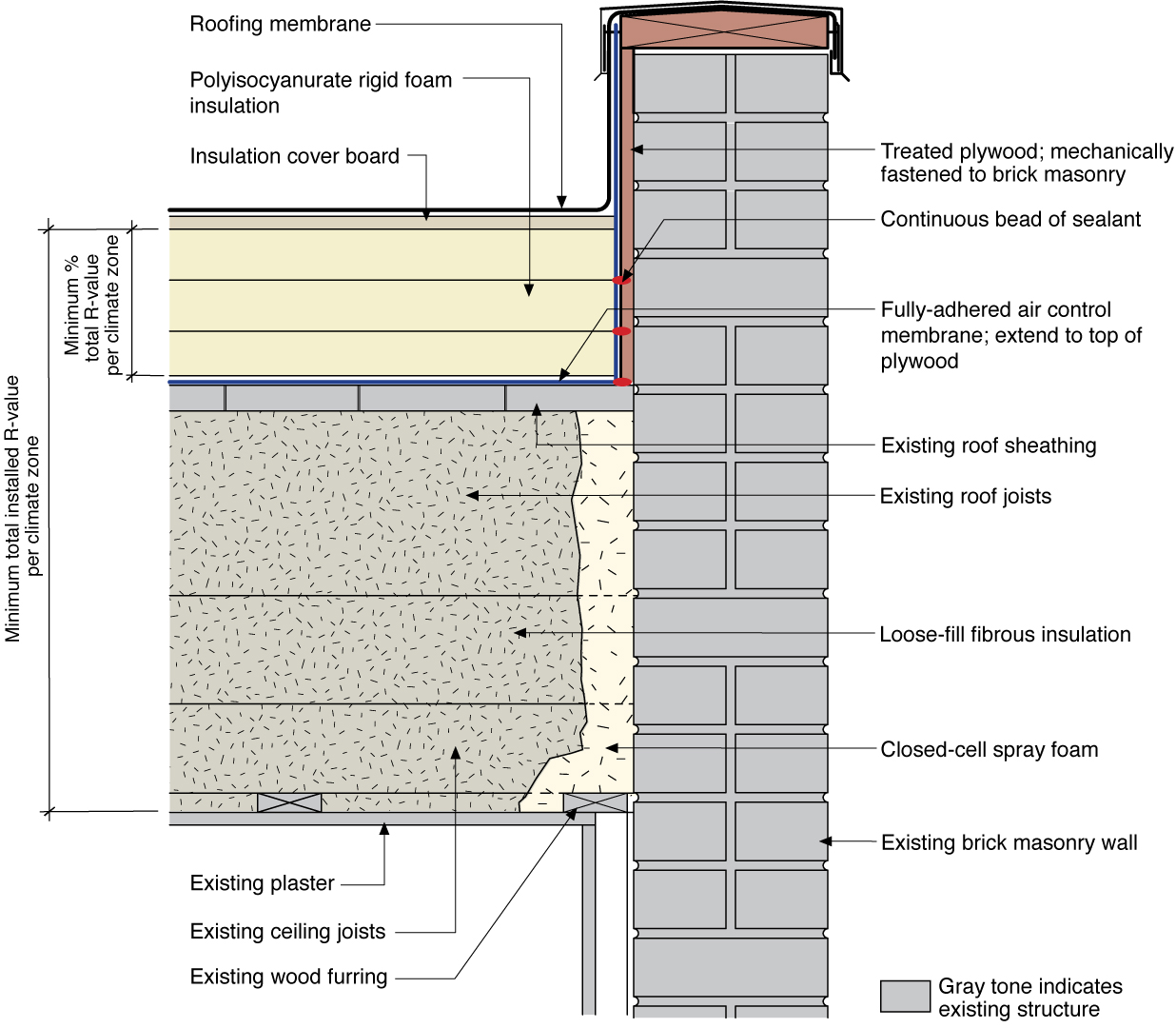
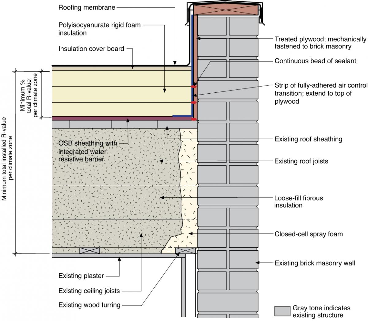
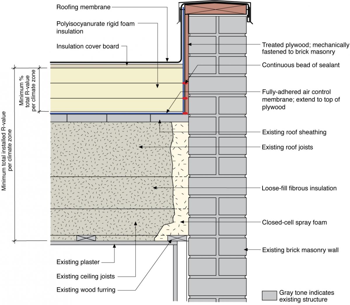
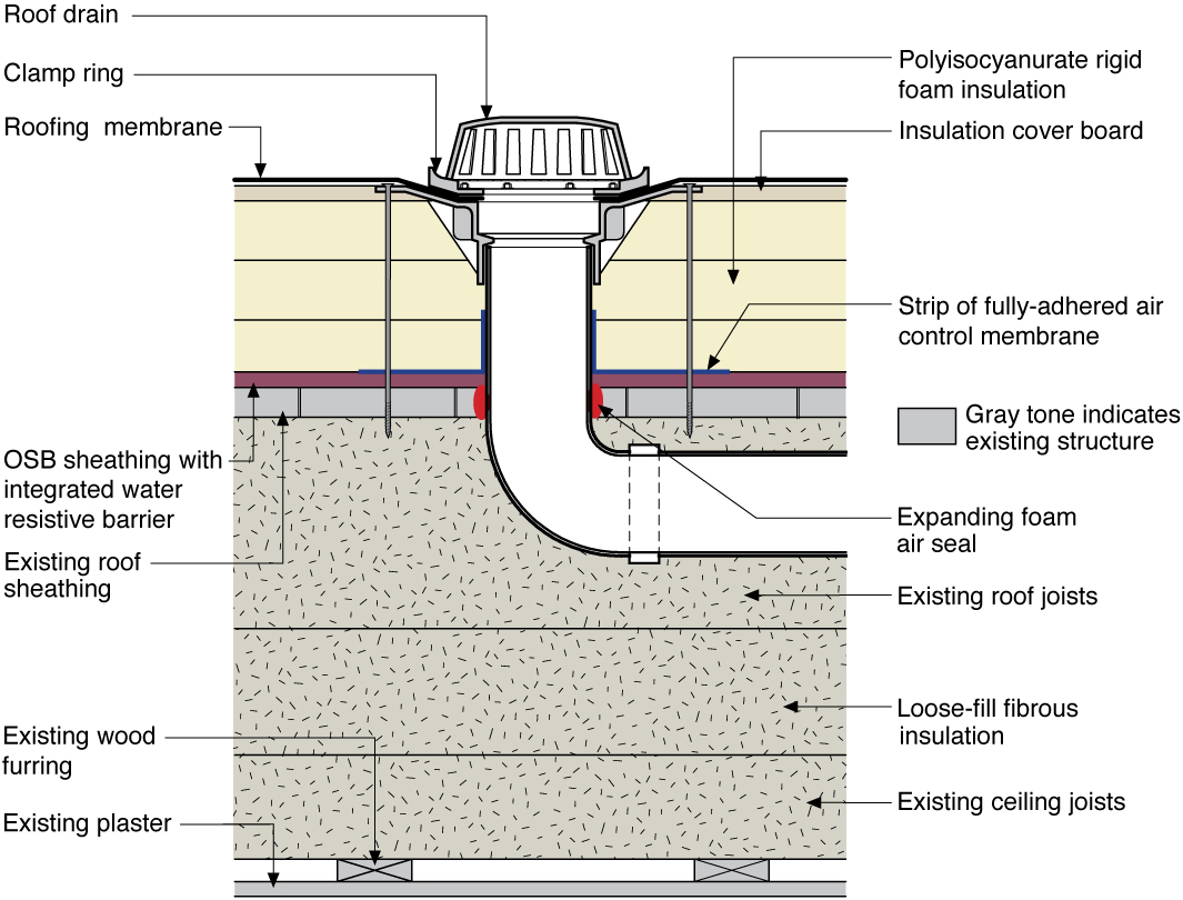
When a flat roof is retrofitted by adding rigid foam insulation above the existing roof sheathing, the new air and water control layers must be carefully integrated with the existing roof structures.
The assembly shown here is an unvented roof assembly and must meet relevant code requirements (Table R806.4 Insulation for Condensation Control of the 2009 IRC (ICC 2009a) and Table R806.5 Insulation for Condensation Control of the 2012 IRC (2012a). The ratio of air-impermeable insulation (polyisocyanurate) to air-permeable insulation (cavity fill) must be sufficient to avoid condensation problems. Assemblies with greater depth of cavity fill insulation require more rigid board insulation. Per 2012 IRC Section806.5, the interior of the roof (gypsum board or plaster) can have a Class II or Class III vapor retarder; a Class I vapor barrier (polyethylene) is prohibited as it will eliminate drying of the assembly. For further explanation, see IRC FAQ: Conditioned Attics.
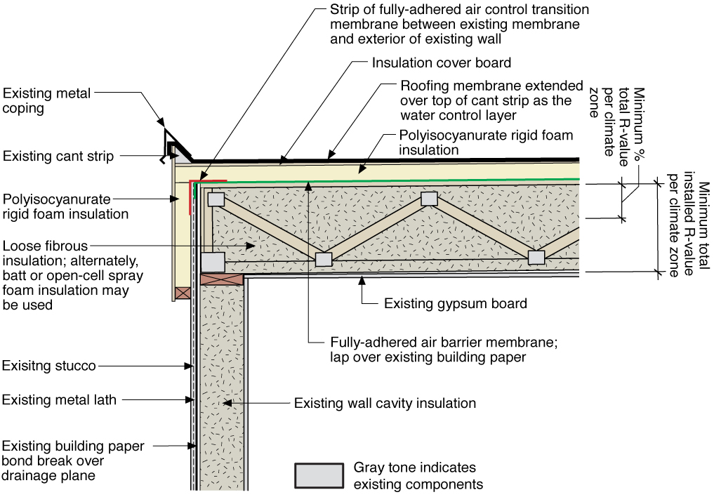
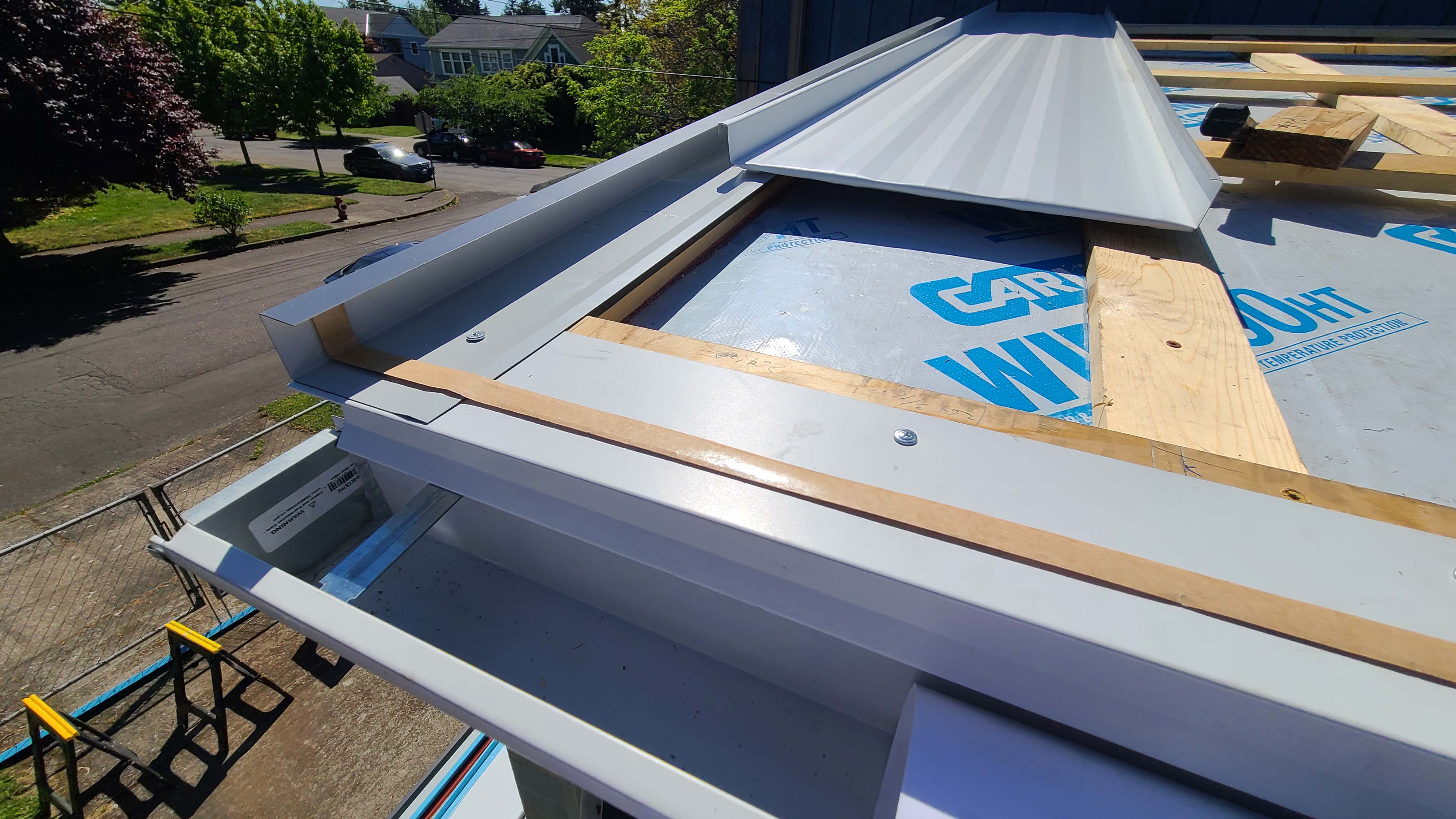
Polyisocyanurate is a suitable rigid foam for installing above the roof deck. The rigid foam can be installed over new sheathing coated with an integrated water-resistive barrier as shown in Figure 1 or the insulation can be installed over the existing roof sheathing, which is first covered with a fully adhered air control membrane that extends up the parapet sides above the flat roof as shown in Figure 2. If foil-faced polyisocyanurate rigid foam insulation is used, a protective layer of insulation cover board should be installed over it prior to installing the roofing membrane water control layer, as shown in Figures 1, 2 and 3. Glass fiber-faced polyisocyanurate can be installed without an insulation cover board.
“Flat” roofs should never be flat. All low-slope roofs must be sloped to drains (as shown in Figure 4) or scuppers at a minimum slope of ¼ inch per foot (ASTM 2009). It is vital that any roof penetrations (drains, skylights, or mechanical curbs) are properly flashed to prevent water entry. The materials that form the water control layer (in this case the roof membrane) should overlap each other in shingle fashion or be sealed in a watertight manner (in the field of the roof if the slope is insufficient to rely on shingle-lapped water shedding).
Skylights, mechanical curbs, and other roof penetrations must be integrated into the roof’s drainage plane(roofing membrane) (see Figures 5 and 6). Membranes or formable flashings that line these curbed openings are all elements of the roof water control layer. These approaches work best when they are sloped toward the roof drain, so that rainwater is directed off of the building.


How to Re-Roof a Flat Roof
Inspect the structural integrity of the roof. Pooling water (seen in Figure below) is a sign that more slope and drains or scuppers are needed. Remove the existing roof membrane, insulation, and sheathing (where needed) and check the roof framing for any deficiencies, rot, insect damage, etc. (see Figure below). Do not proceed if any repairs need to be performed. Based on the findings, revise the roof assembly and review specific detailing as needed. Follow the minimum requirements of the current adopted building and energy codes.

Figure 7. The existing flat roof before removal of membrane shows lack of slope allowing water to pool on the surface. (Source: Building Science Corporation.) 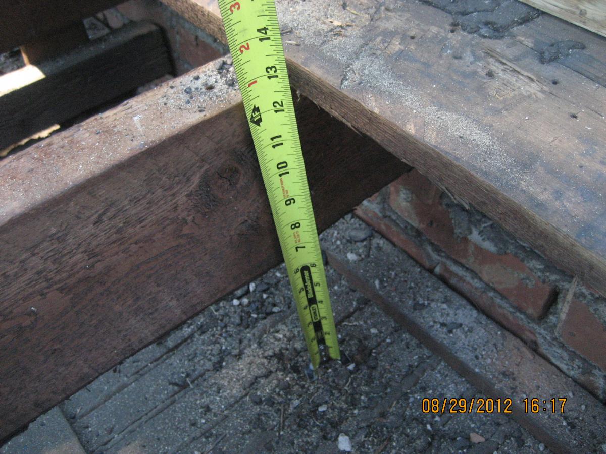
Figure 8. Sheathing is removed from a flat roof to retrofit with air sealing, insulation, and water control layers. (Source: Building Science Corporation.) Remove two or three roof sheathing boards near the perimeter of the roof, leaving one or two boards at the parapet (Figure below). Mechanically fasten a strip of pressure-treated plywood to the interior vertical face of the parapet to allow for attachment of the strip of fully adhered air barrier membrane. Install a strip of OSB sheathing with an integrated water-resistive barrier at the roof perimeter adjacent to the parapet on top of the remaining board sheathing (Figure below). Provide a continuous bead of sealant between the existing board sheathing and a strip of new roof sheathing.
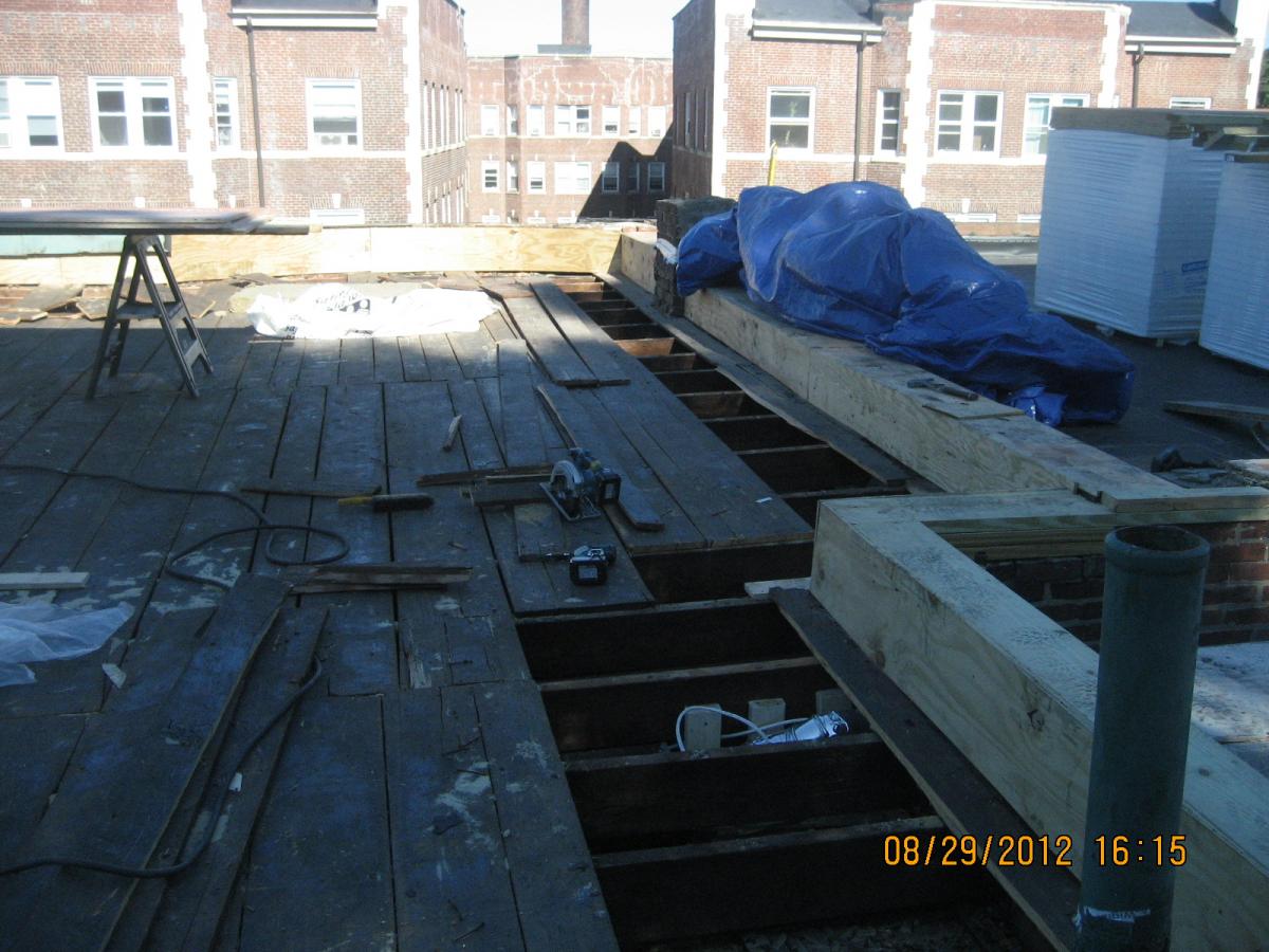
Figure 9. The existing sheathing boards are removed near the perimeter of the flat roof and pressure-treated plywood is installed at the vertical face of the parapet. (Source: Building Science Corporation.) 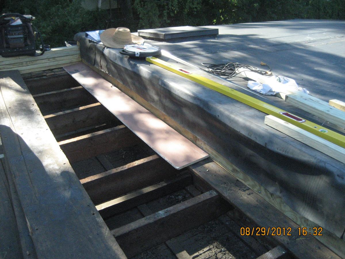
Figure 10. A strip of OSB sheathing is installed along the perimeter when retrofitting a flat roof with a parapet. (Source: Building Science Corporation.) Spray 2 inches of closed-cell spray foam in the roof cavity at the wall perimeter to create an air barrier connection between the wall and the roof, and to provide adequate thermal resistance to prevent condensation (Figures below). The area should be free of debris and dust prior to spraying for adequate adhesion. Install fibrous insulation (e.g., cellulose) in the rafter cavities beneath the existing board roof sheathing (Figures below). Re-install the roof sheathing boards.
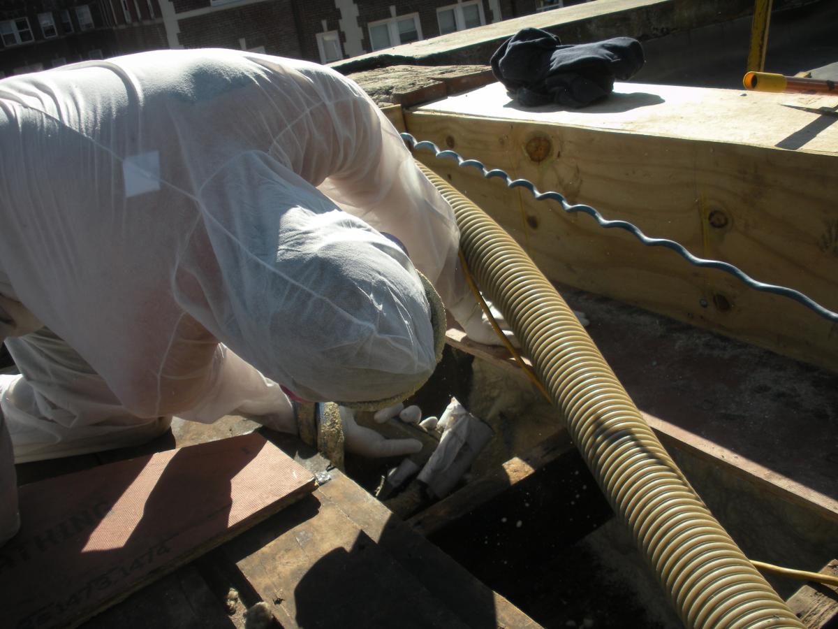
Figure 11. Closed-cell foam is sprayed into roof cavities along the masonry parapet wall to form a continuous air barrier between the wall and the sheathing of the flat roof. (Source: Building Science Corporation.)

Figure 12. Closed-cell spray foam fills the roof joist cavities forming an air barrier between the masonry parapet wall and the roof sheathing. (Source: Building Science Corporation.) 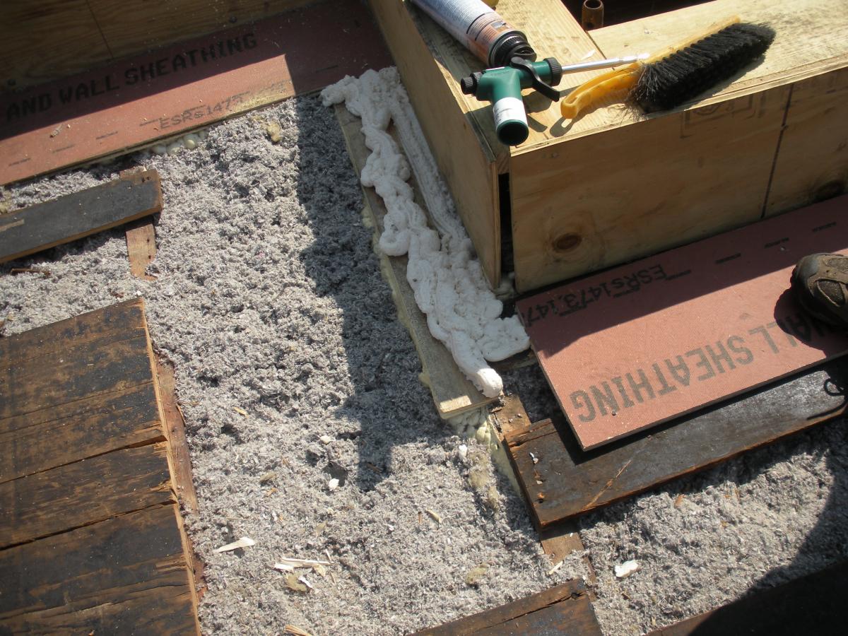
Figure 13. The base of the plywood parapet is air sealed with spray foam and fibrous insulation is installed in the rafter cavities in this flat roof retrofit. (Source: Building Science Corporation.) 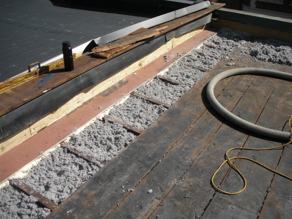
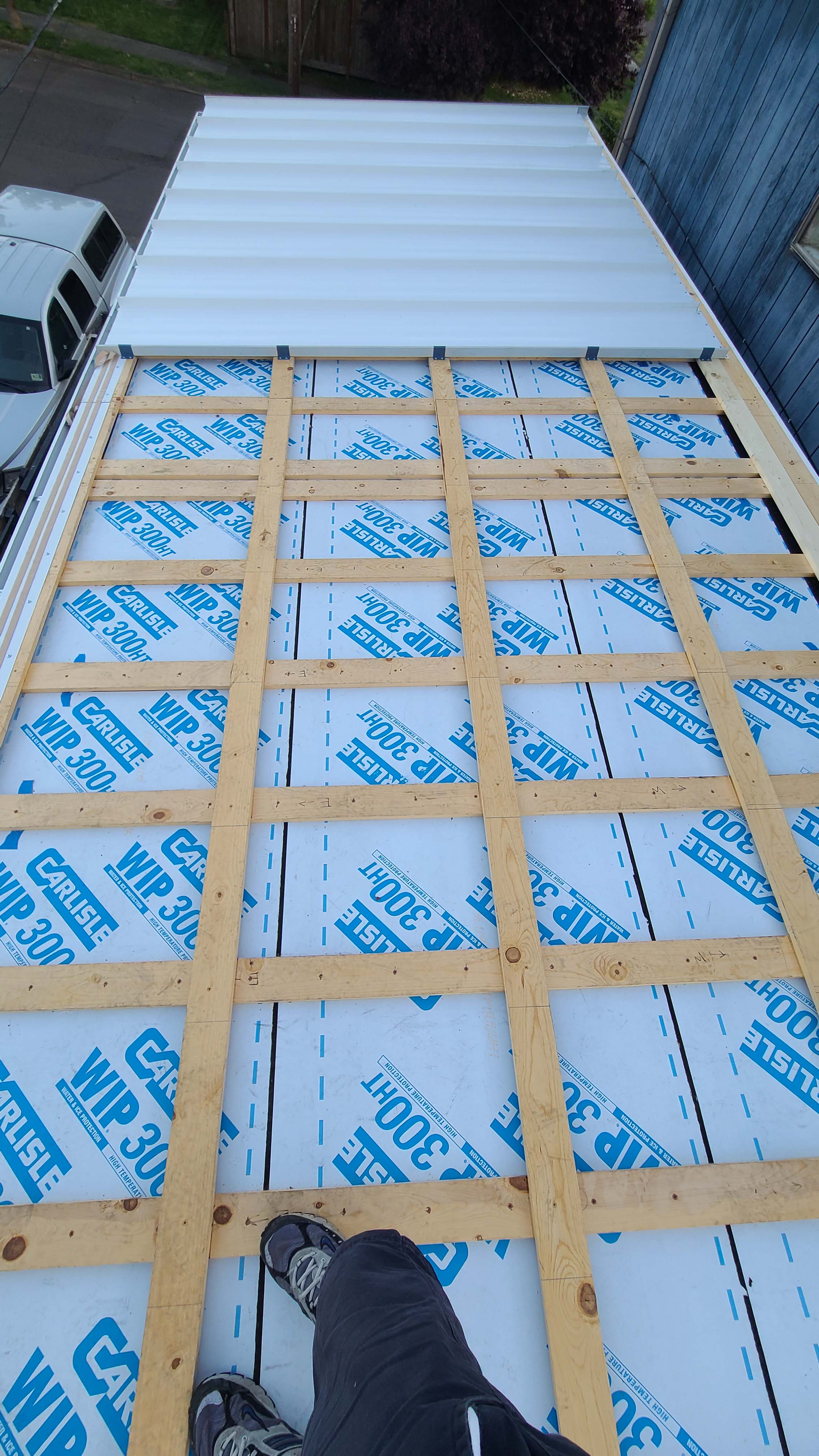
Figure 14. Roofing paper protects the top of the new plywood parapet while the base of the parapet is air sealed with spray foam and fibrous insulation is installed in the rafter cavities in this flat roof retrofit. (Source: Building Science Corporation.) If needed to create a slope, install sleepers (tapered wood furring strips) on the roof rafters prior to installing the new roof sheathing (Figure below). Install OSB sheathing with an integrated water-resistive barrier over the entire field of the roof (Figure below). Seal all of the sheathing seams with appropriate tape that is applied to a clean surface and pressed on with a roller to ensure good adhesion. This coated, taped OSB is the air control layer at the field of the roof. Install a strip of fully adhered air barrier membrane on top of the new roof sheathing at the roof perimeter adjacent to the parapet and extend it to the top of plywood to form an air barrier connection to the parapet wall. Seal all penetrations, such as drains, skylights, and mechanical curbs, in an airtight and durable manner to the air control layer.
ALTERNATELY, instead of the coated OSB, install a fully adhered air barrier membrane over the existing roof sheathing and extend up to the top of the plywood at the parapet to form a continuous air control layer. Seal all penetrations, such as drains, skylights, and mechanical curbs, in an airtight and durable manner.
Figure 15. Sleepers (tapered wood furring strips) are installed over the existing board sheathing to slope the new sheathing toward the drain in this flat roof retrofit. (Source: Building Science Corporation.) 
Figure 16. New coated OSB roof sheathing is installed over the existing sheathing of the flat roof and taped at the seams to provide a continuous air barrier. (Source: Building Science Corporation.) Install polyisocyanurate rigid foam insulation over the roof sheathing (Figure below). The ratio of air-impermeable insulation (polyisocyanurate) to air-permeable insulation (cavity fill) must be sufficient to avoid condensation problems, per Section R806.4 of the 2009 IRC (ICC 2009a) and Section R806 of the 2012 IRC (2012a). If tapered sleepers are not installed, provide tapered insulation to ensure the roof is sloped to drain. Fit the joints of the insulation together tightly. When installing multiple layers, offset the seams in two directions, add a continuous bead of sealant at the perimeter of the roof between each layer, and tape the seams of each layer. Install wood blocking for future photovoltaic (PV) panel installation (Figure below). The surface of the blocking must stand proud of the roof deck to reduce water penetration risks at fastener penetrations (Figure below). Install insulation cover board (typically fiberglass-faced gypsum board) over the polyisocyanurate rigid foam insulation. Ensure compatibility of the cover board with the roof assembly.
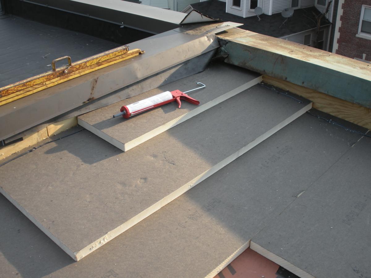
Figure 17. Polyisocyanurate rigid foam insulation is installed in multiple layers with staggered, taped seams over the flat roof. Note the continuous bead of sealant at the roof perimeter between each layer. (Source: Building Science Corporation.) 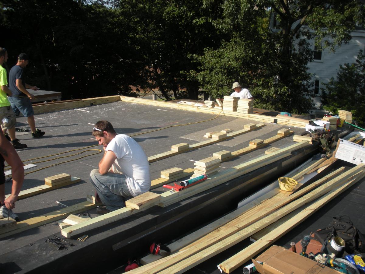
Figure 18. Wood blocking for future PV panel installation is installed in the layers of polyisocyanurate rigid foam insulation during a flat roof retrofit. (Source: Building Science Corporation.) 
Figure 19. The wood blocking for future PV panel installation extends above the surface of the top layer of polyisocyanurate rigid foam insulation installed as part of a flat roof retrofit. (Source: Building Science Corporation.) Install roofing membrane over the insulation cover board and lap it over the parapet to provide a continuous water control layer (Figure 20). Seal all penetrations, such as drains, skylights, mechanical curbs, and PV blocking against water leaks per new construction best practices (Figures 21, 22, and 23). Install metal cap flashing at the parapet over the roofing membrane. Provide drip edges on either side of the cap flashing to prevent staining of the building façade. (See Figure below and BSI-050: Parapets—Where Roofs Meet Walls.)

Figure 20. Roofing membrane is installed over polyisocyanurate rigid foam insulation and insulation cover board that has been cut to fit around locations for blocking for the PV system rack. (Source: Building Science Corporation.)
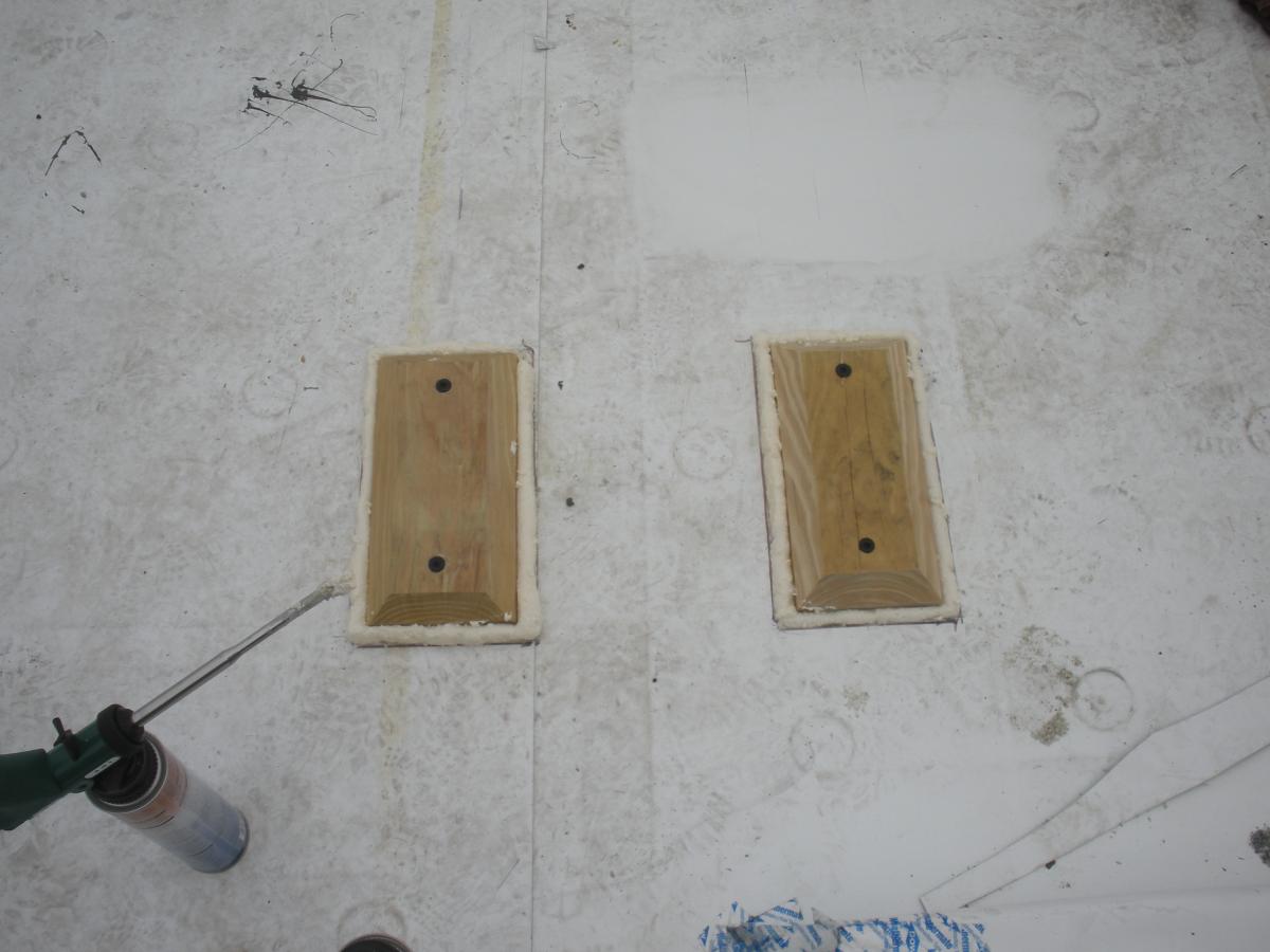
Figure 21. Blocking installed on a flat roof for a PV system rack is sealed around the edges with sealant then will be covered with self-adhering roof membrane to prevent water leakage. (Source: Building Science Corporation.)
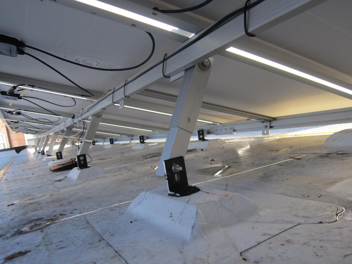
Figure 22. The blocking is completely flashed with roofing membrane before the PV rack hardware is attached on a flat roof. (Source: Building Science Corporation.) 
Figure 23. Strips of roofing membrane are used to flash around a skylight on a flat roof retrofit. (Source: Building Science Corporation.) 
Figure 24. Metal cap flashing is installed over the roof parapet and extends down over the roofing membrane (which extends up the sides of the parapet wall). A drip edge on each side of the flashing directs water to drip away from the walls, to minimize the likelihood of staining. (Source: Building Science Corporation.) Install walking mats to protect the membrane surface when accessing the flat roof (Figure below).

Figure 25. The retrofitted flat roof has PV panels and walking mats installed over the roofing membrane. (Source: Building Science Corporation.)
Ensuring Success
Provide the water control layer in the roof assembly and install it in a continuous manner. Ensure it is connected to the water control layer of the adjacent assemblies and roof elements, such as skylights, mechanical curbs, and drains.
Provide the air control layer in the roof assembly and install it in a continuous manner. Ensure it is connected to the air control layer of the adjacent assemblies and roof elements, such as skylights, mechanical curbs, and drains.
Slope the roof deck to a drain or scupper (with a minimum slope of .25 inch per foot).
The ratio of air-impermeable insulation (polyisocyanurate) to air-permeable insulation (cavity fill) must be sufficient to avoid condensation problems, per Section R806.4 of the 2009 IRC (ICC 2009a) and Section R806 of the 2012 IRC (2012a).
Remediate any hazardous conditions that will be affected (e.g., exposed or aggravated) by the planned work. Examples of hazardous materials that may be found in roof assemblies of existing structures include (but are not limited to) lead, asbestos, mold, animal dropping/remains, etc. Follow applicable laws and industry procedures for mitigation of hazardous materials. Engage the services of a qualified professional when needed.
Provide minimum combustion safety by providing direct-vent sealed-combustion equipment or forced draft equipment (see Direct Vent Equipment). When furnaces, boilers, and water heaters are installed within the home’s pressure boundary, ideally this equipment would be direct-vent sealed-combustion equipment. If existing equipment is not direct-vent sealed-combustion or forced draft, the homeowners must decide whether to
- replace equipment with direct vent or forced draft equipment, or
- retrofit forced-draft to existing equipment.
Provide whole-house and local exhaust (source control) mechanical ventilation complying with Section M1507 of the 2012 International Residential Code. Mechanical ventilation may be installed as part of the larger attic/roof retrofit project.
Region
The roof assembly should be designed for a specific hygrothermal region, rain exposure zone, and interior climate.
The map in Figure 1 shows the climate zones for states that have adopted energy codes equivalent to the International Energy Conservation Code (IECC) 2009, 12, 15, and 18. The map in Figure 2 shows the climate zones for states that have adopted energy codes equivalent to the IECC 2021. Climate zone-specific requirements specified in the IECC are shown in the Compliance Tab of this guide.
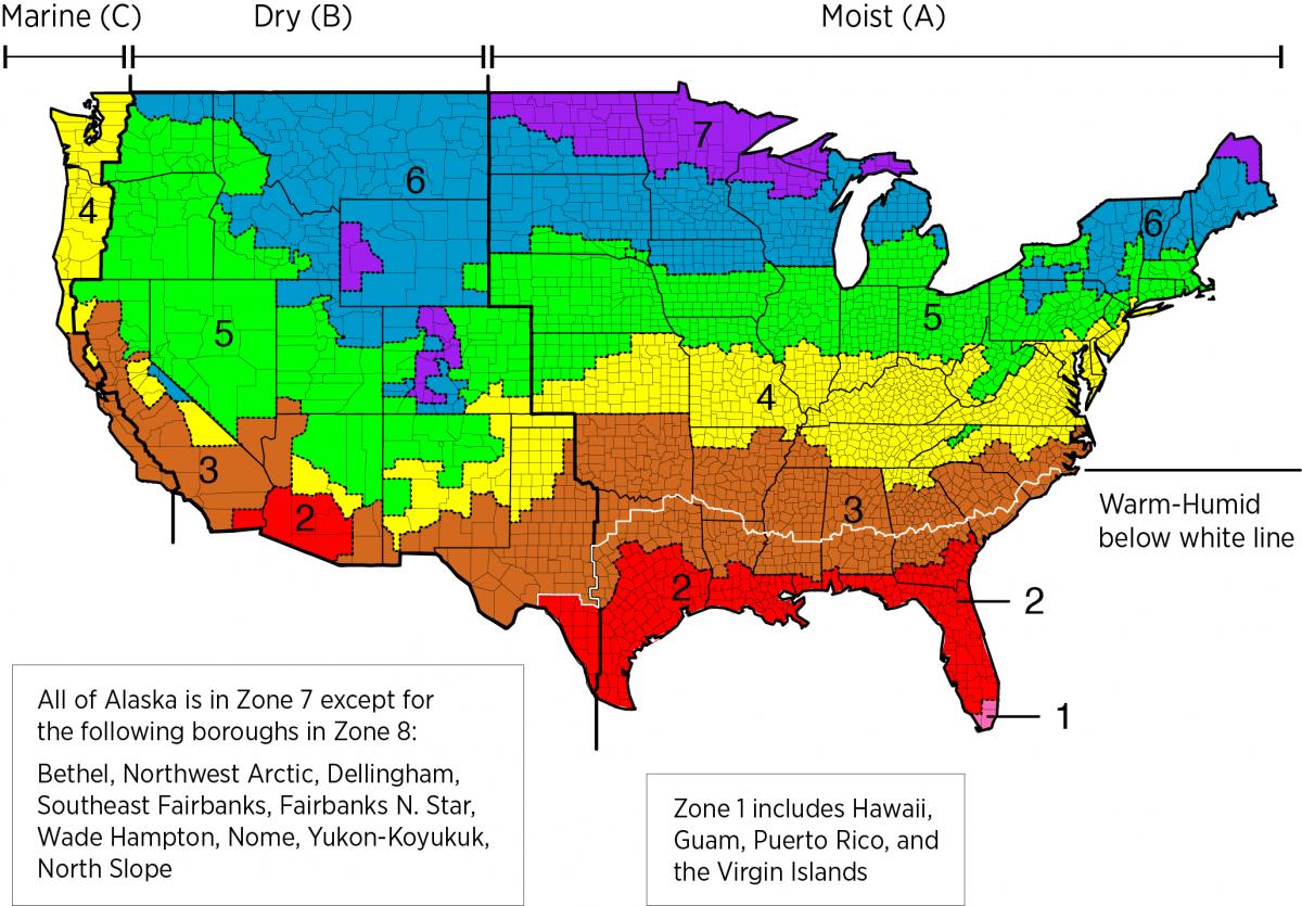
Figure 1. Climate Zone Map from IECC 2009, 12, 15, and 18. (Source: 2012 IECC)

Figure 2. Climate Zone Map from IECC 2021. (Source: 2021 IECC)
The insulation levels should be based on the minimum requirements for vapor control in the current adopted building code and the minimum requirements for thermal control in the current energy code. Table 1 provides the minimum thermal resistance (R-value) requirements specified in the 2009 IECC (ICC 2009b) and the 2012 IECC (ICC 2012b) based on climate zone for roof assemblies.
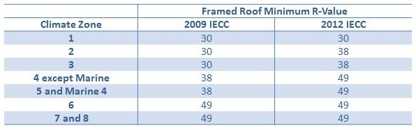
Table 1. Attic Insulation Requirements in the 2009 and 2012 IECC. (Source: 2009 IECC and 2012 IECC)
It is important to maintain a sufficient ratio of exterior insulation to total roof assembly insulation. In colder climate zones, the amount of exterior (rigid) insulation needed to avoid condensation problems increases. Table 2 provides information on minimum levels of air impermeable insulation for condensation control specified in Table R806.4 Insulation for Condensation Control of the 2009 IRC (ICC 2009a) and Table R806.5 Insulation for Condensation Control of the 2012 IRC (2012a).
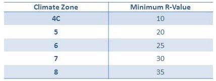
Table 2. Insulation required for Condensation Control in the 2009 and 2012 IRC. (Source: 2009 IRC and 2012 IRC)
Training
Right and Wrong Images
Source
Source
Source
Source
Compliance
More Info
Case Studies
References and Resources
*For non-dated media, such as websites, the date listed is the date accessed.
Contributors to this Guide
The following authors and organizations contributed to the content in this Guide.
Building Science Corporation, lead for the Building Science Consortium (BSC), a DOE Building America Research Team
Questions? Comments? Contact our webmaster.