

Scope
Analyze boiler and building performance and install thermostatic radiator valves (TRV) to reduce temperatures in over heated spaces. Assess site conditions to determine the appropriate TRV retrofit strategy, and make necessary repairs to the heating system to allow the TRVs to function properly.
Installation of the TRV itself is a fairly straightforward and simple process. However, placement of the sensor within the room will require a thoughtful, and perhaps iterative, approach to maximize the control accuracy. This is discussed further under Ensuring Success.
Once TRVs are installed, commission the boiler controls to ensure that an appropriate amount of heat is being delivered to the building and that the boiler is not short-cycling because of the newly reduced demand.
Lastly, a critical step is resident education, without which the TRV installation may be rendered ineffective. Hold resident workshops to familiarize building tenants with the technology and its proper use. If tenants formerly opened their windows to mitigate overheating, make sure that they understand this is no longer necessary and can potentially reduce their comfort by interfering with the function of the TRVs.
See the Compliance Tab for links to related codes and standards and voluntary federal energy-efficiency program requirements.
Description
There is a large stock of multifamily buildings in the Northeast and Midwest with space heating provided by hot water or steam. Typically, residents of these buildings do not pay for heat directly (i.e. heating fuel serves a central plant and use is not sub-metered). Losses from these systems are typically high and a significant number of apartments are overheated much of the time. This is often evidenced by open windows on winter days. Controls and distribution are often faulty and improvements to them can be more cost-effective than boiler replacements.
Thermostatically controlled radiator valves (TRVs) are one potential strategy to combat this problem. TRVs have been in existence for many decades. They are commonly used in Europe and in commercial buildings, but have not been widely accepted by the residential retrofit market in the U.S. Anecdotal evidence suggests that heating systems engineers and contractors have a variety of opinions on the effectiveness of TRVs, illustrating a lack of consensus on this potentially important energy efficiency measure. A review of the limited available literature found that in one study as much as 15% heating fuel savings was accomplished through TRV retrofits, but only if other measures are implemented in conjunction with TRVs.
Assess boiler and building performance to determine if TRVs are an appropriate upgrade for the building. See the Ensuring Success tab for other tips on determining when TRVs make sense.
- Monitor the existing space temperature spread across typical apartments during heating season and diagnose the causes of variation before a retrofit strategy is chosen. This will allow the consultant and building owner to better assess the potential benefits of a whole-building TRV retrofit, selective installation of TRVs in some units, or simply balancing the steam distribution venting. If feasible, an iterative approach in which the venting and boiler controls are tuned first and TRVs are subsequently considered if overheating control opportunities remain is a preferred means of minimizing unnecessary costs. An average heating season apartment space temperature of 75°F or less probably does not merit wholesale use of TRVs; balancing and maintenance alone may be able to reduce the temperature spread between the hottest and coldest rooms and reduce the output of the boiler to bring the average space temp down a few degrees, without making any tenant cold.
- Determine whether some parts of the building might be experiencing drastically different heating loads than the rest. For example, if there is a block of units with large south-facing windows, or a wing of the building exposed to high winds. In such cases, even if the radiator air vents have been regularly maintained and the mains and riser venting is already balanced there might still be a large space temperature spread. TRVs may be an excellent way to limit heat output to the hotter areas and reduce the average space temperature.
- Repair failed air vents and balance uneven steam main venting either in conjunction with or before TRV installation occurs. In some apartments this is likely to increase heat supply. An increase in space temperature for underheated apartments would be a desirable result of air vent maintenance and steam vent balancing; however, this may reduce expected heating fuel savings if good space temperature data has not been obtained beforehand to provide an accurate picture of existing building overheating. Once under-heating has been solved TRVs may provide a useful upper bound to apartment space temperatures.
- Tune the building’s boiler so that is able to deliver dry steam at low pressure (no more than 2 psi) – if this is not the case, water hammer and excess operating pressures may damage the TRVs and/or limit their effectiveness. Ensure that all radiators are properly pitched and that none of the heating system components are in imminent need of repairs.
- Consider the building’s resident population. Are there mostly elderly tenants who desire warmer spaces (75°F+), or younger tenants who might prefer cooler temperatures? Is it a high-end building? Would the tenants tolerate TRVs locked at 70°F or, conversely, would it be a value-add to have adjustable TRV radiator control for each room? Do the tenants have an ingrained window opening habit (as is often the case in previously overheated buildings) that could mitigate the effectiveness of TRVs without proper education?
- If possible, model the property with building simulation software to give insight to the cost-benefit analysis.
- While working on the heating system, obvious improvements such as pipe insulation should also be implemented.
Central hydronic and steam space heating systems typically work by generating heat in a central location (the boiler or boilers) and transmitting that heat to the various parts of the building through pipes carrying hot water or steam. Often, multifamily buildings with these systems have one or just a few heating zones with no or very limited ability to control the heat locally. There are three main types of such space heating distribution systems in the U.S.:
- Single pipe steam systems: In this type of system, steam is generated in a boiler and then transmitted to different parts of the building through a network of pipes that gradually diminish in size as they become more distant from the boiler. The steam then enters radiators in the spaces, gives up it heat, and then condenses into the bottom of the radiator from which it drains down to the boiler through the same pipes that it came up in. Venting of steam lines is critical in single pipe steam systems; only with properly sized and operating air vents on headers, risers and radiators will steam reach all radiators at approximately the same time, which is a hallmark of a well-tuned system. Single pipe steam systems are commonly found in older buildings, especially those built before 1970.
- Two pipe steam systems: In these heating systems, steam is transmitted through one pipe and the condensate (water) returns to the boiler through a second pipe connected to the back end of the heat emitter (radiator). Two pipe systems rely on steam traps to prevent steam from passing through the radiator and exiting into the condensate return pipe. Both one pipe and two pipe steam systems are typically controlled by warm weather shut off controls in which the boiler stops supplying heat to the building if the outdoor air temperature reaches a predetermined threshold. In addition, outdoor reset controls cycle the steam supply as a function of outdoor temperature to deliver only the heat required given the current weather. Two pipe steam systems are common in larger buildings built after 1970.
- Hot water systems: Hot water systems are also common in multifamily buildings. Boilers provide hot water to the radiators or other heat emitters and the return water is pumped back to the boiler to be reheated. Often multifamily hot water systems have circuit setters or balancing valves to make one-time or periodic adjustments to balance the heat distribution. Hot water systems are also two pipe systems. Most multifamily hot water boilers are controlled by outdoor reset control where the supply water temperature is controlled as a function of outdoor temperature.
Efficient control of heating systems has a large influence on energy savings as well as the thermal comfort of residents. According to the Department of Energy, overheating can increase annual heating fuel usage by as much as 3% for each degree Fahrenheit above the desired space temperature set-point.
Depending on the system type, there are a number of ways to balance the system and even out distribution, after which the central heat supply can be reduced. For one-pipe steam, venting is a primary means (McNamara, 1995) (Jayne Choi, 2012). Two-pipe systems can often benefit from properly sized orifices and correcting faulty steam traps (Gifford, 2003). For hot water systems, adjusting the balancing valves can help. However, for many buildings this may not be sufficient, meaning that local controls will be required. One room-level strategy is using a local powered two-way zone valve and thermostat. This strategy provides a high level of control but requires low voltage power to the valve and is expensive (at least $350 per radiator). TRVs are a potentially lower-cost room-level strategy, particularly for certain applications discussed in this guide.
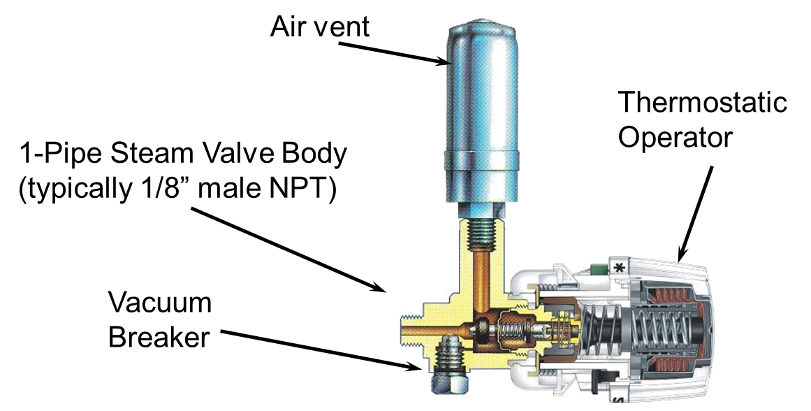
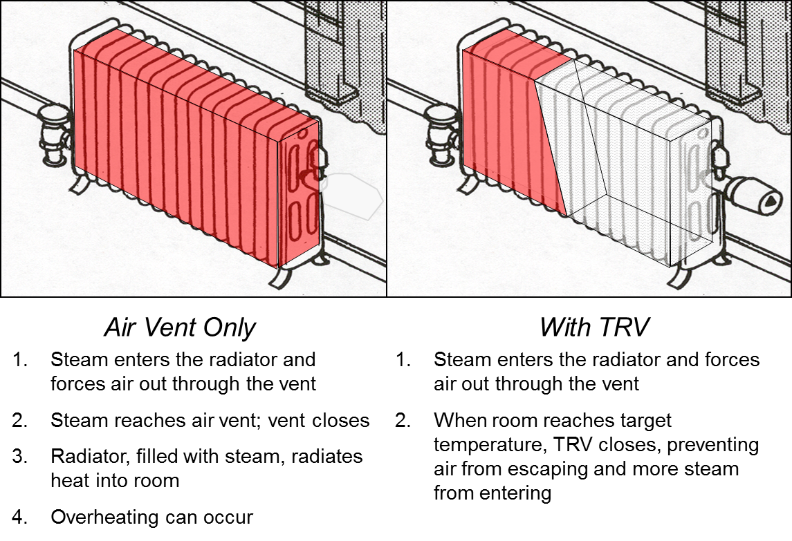
Steam TRVs do not require electric power. They consist of a valve and an operator (plus an air vent in the case of one-pipe steam systems) (Figure 1). A fluid-filled capsule inside the TRV operator expands as room temperature increases. As it expands it closes the valve, blocking entry of steam or hot water into the heat emitter. In the case of one-pipe steam, it blocks the release of air through the vent which prevents steam from entering the radiator (Figure 2). When the room temperature decreases, the capsule contracts, allowing hot water or steam to enter (or air to escape one-pipe systems). A knob on the operator allows an occupant to adjust the temperature at which heat is allowed into the heat emitter (Gifford, 2004).

Ensuring Success
Existing Level and Character of Overheating
If the existing average space temperature is above 72°F but not excessively so, this would reduce (but not eliminate) the potential for the TRV retrofit to reduce building-wide space heating demand compared to buildings where the existing space-heating average temperature is, for example, 80°F or greater.
If the existing variation in average temperature throughout the building is small, this would also present less opportunity for TRVs to reduce overheating in comparison to a building in which heating demand varies greatly from apartment to apartment. For example, in a building where some apartments have large south-facing windows (high solar loads), a building with a wing exposed to high wind-wash, or one in which the residents’ thermal comfort levels vary greatly, the superintendent is typically forced to maintain a high average space temperature to satisfy the coldest apartments. TRVs could potentially reduce the need for this by limiting heat emitter output in rooms with less heat demand while the boiler output continues to satisfy rooms with greater heat demand.
One-Pipe Convector Radiator Considerations
There are several key differences between the application of thermostatic radiator valves in a one-pipe convector radiator system versus those with two-pipe systems and/or cast iron radiators. With two-pipe steam, the TRV can be placed at the radiator inlet where it is able to block steam entirely from entering the radiator when the TRV is closed. In a one-pipe steam application TRVs are installed at the vent side of the radiator, principally because of debris and condensate clogging issues at the inlet, and higher labor costs. A one-pipe TRV in the vent position can work in either of two ways:
- If the space temperature has already satisfied the sensor and the TRV is closed before a steam cycle begins, it can prevent the entire mass of air in the radiator from exiting the radiator body. The cycle runs and no heat is added to the space (as long as the steam pressure is low).
- If the TRV is open at the beginning of a steam cycle and closes when the air has only been partly displaced from the radiator body, it will effectively limit the volume of radiator body that can receive steam over the duration of the remaining steam cycle.
The second scenario requires that once a steam cycle begins the TRV sensor is able to actuate the valve in a shorter time span than that in which the air is displaced from the radiator. A large cast-iron radiator can take eight to ten minutes to fill completely with steam, whereas convectors will fill in two minutes or less. The reaction of the TRV has to happen, therefore, in less than ten minutes from the beginning of the steam cycle for cast iron and in less than two minutes for convectors. Expansion of the sensor material happens within seconds; the limiting factor is the time required for the establishment of a convection current within the room that bathes the TRV sensor in air that exceeds its setpoint temperature. The location in which the TRV sensor is placed within the room is then a critical factor in responding to the higher temperatures in the convective current. Also, the TRV temperature setpoint itself, relative to the desired space temperature, may impact this response time.
Boiler Control Setpoints
Boiler operating pressure and outdoor reset curve settings may potentially affect both the ability of TRVs to control individual radiator heat output and the building-wide effect of TRVs on heating fuel usage. As an example, a steam boiler in a typical building may be set to operate at a range of 2-5 pounds per square inch (psi) above atmospheric pressure. Neglecting for pressure drops along the steam mains and risers, 5psi at a radiator would compress the trapped air volume by approximately 25% and therefore allow that radiator to emit a quarter of its maximum heat output even when the TRV has successfully closed. If the operating pressure could be reduced to a maximum of 2psi, this would only allow 12% of the radiator to fill with steam in the same case, increasing the ability of the TRV to limit radiator heat output.
Resident Behavior
Tenant behavior is difficult to predict and influence. Frequent window opening by the residents may be an established means (read: habit) of controlling overheating. Providing balanced steam heat and consistent space temperatures is a pre-requisite to TRV installation for other reasons mentioned in this guide, and also to reduce the need and habit for tenants to regulate space temperatures in this way. If this behavior persists after TRVs are installed, it is possible that a given TRV sensor would never exceed its setpoint temperature and therefore, never close to limit radiator output. Resident education is key for this reason.
Ventilation System
Older buildings, which are more likely to have one-pipe steam heat, are often not served by a central mechanical ventilation system to bring fresh air into the living spaces and exhaust stale air and odors from the kitchens and bathrooms. Rather, operable windows controlled by building residents are the principal means of ventilation. This is a case where the design of the building is intrinsically sensitive to tenant behavior – cooking habits and individual preferences are expected to vary the ventilation levels. Window ventilation is a separate phenomenon from window-mediated overheating control, but may also contribute to improper TRV function.
TRV Considerations
- Variety of TRV makes and models: TRVs are manufactured by a number of companies, each with multiple models that are subject to design modifications over time. In addition, there are two main types of TRVs operation: wax and bellows types (bellows types in turn can be either liquid or vapor filled), affecting response time.
- TRV adjustments: Depending on the goals of the building owner, you have the option of installing TRVs that are adjustable by residents or that come locked at a specific temperature from the factory. Additionally, the placement of the TRV dial within a radiator cabinet may make it more difficult to adjust, while wall-mounted options are also available for resident convenience.
- Radiator inlet valve seals and other connections: TRVs, as well as radiator air vents, function on the premise that they are able to control the movement of air within a radiator. To the extent that any leaks exist at threaded connections within the radiator assembly or at the inlet valve seal, this function may be compromised and/or steam may escape directly into the conditioned space.
- TRV sensor placement: TRV sensors may experience lower or higher temperatures as a result of their placement within a room. For example, sensors can be placed outside of or within convector cabinets (in the direct return air stream), on the wall next to the radiator, on the TRV itself, or on an interior wall. Placing the sensors out of the way and within radiator cabinets may protect them from unintended impacts and wear that can damage delicate capillary tubes; however, it may also expose them to too much or too little heat and limit effectiveness of the TRV.
- Rated close-off pressure: It is also important to ensure that the TRVs in your installation can close properly against the operating pressures generated by the steam system. Some TRV manufacturers report that their products are built to withstand up to 15psi without risk of mechanical failure – of course, 15psi as an operating range for the steam system would be grossly inappropriate for the reasons discussed above – but be sure to check with the manufacturer.
Cost-Benefit Analysis
TRV installation costs can vary widely, partly due to the product used and in part to the installation method employed – i.e., do-it-yourself or by licensed contractors. The degree of existing overheating in the building and length of the heating season will also vary. As a result, in some circumstances TRVs can be cost effective as a whole building solution, while in others they may be suitable only for specific problem overheating areas.
Building energy modeling of TRVs installed in typical masonry buildings in the New York City climate show that at an installed cost of $140, installation will only have a positive payback if the average building space temperature is lowered by 6°F or more for typical natural gas fired boilers.
Region
Thermostatic radiator valves are a heating system retrofit technology appropriate for climate zones 4 and greater. As discussed under Ensuring Success, modeling analysis that includes local installation costs, fuel costs, boiler efficiency, overheating temperature data, and heating season weather can help to determine if TRVs will be beneficial and cost effective for a specific building.
The map in Figure 1 shows the climate zones for states that have adopted energy codes equivalent to the International Energy Conservation Code (IECC) 2009, 12, 15, and 18. The map in Figure 2 shows the climate zones for states that have adopted energy codes equivalent to the IECC 2021. Climate zone-specific requirements specified in the IECC are shown in the Compliance Tab of this guide.
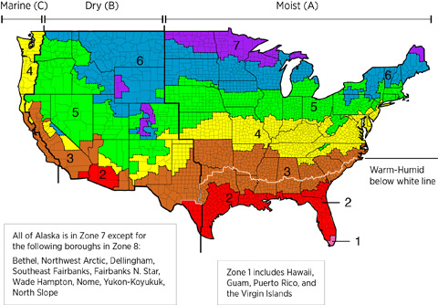
Figure 1. Climate Zone Map from IECC 2009, 12, 15, and 18. (Source: 2012 IECC).

Compliance
Building owners are responsible for maintaining minimum heat in most municipalities. Check your local regulations.
More Info
References and Resources
*For non-dated media, such as websites, the date listed is the date accessed.
Contributors to this Guide
The following authors and organizations contributed to the content in this Guide.
The Levy Partnership, Inc., lead for the ARIES Collaborative, a DOE Building America Research Team
Questions? Comments? Contact our webmaster.