
Rigid Foam Insulation Installed Between Existing House and Garage Walls

    Scope
    Scope Images
    Image
    Rigid foam insulation is installed on the garage side of the shared garage wall and roof of an existing home
    Scope

    Upgrade walls that separate the garage from the house by providing a continuous air control layer on the garage side of the wall and adding rigid foam insulation, as follows:

    • Remove the interior finish material (e.g., gypsum board; lath and plaster) along the garage return walls and ceiling where they interface with the shared wall to allow access for creating an air sealing control layer.
    • Block (with additional gypsum board or other rigid material) and seal all gaps between the existing wall finish (e.g., gypsum board; lath and plaster) and the inside face of the exterior wall and roof sheathing. Seal any seams or openings in the rim joist if exposed.
    • Install insulating sheathing.
    • Provide attachment blocking as required to allow for the installation of new interior finishes/fire protection layer (e.g. gypsum board) as required by code.

    See the Compliance Tab for related codes and standards requirements, and criteria to meet national programs such as DOE’s Zero Energy Ready Home programENERGY STAR Single-Family New Homes, and Indoor airPLUS.

    Description
    Description

    When exterior walls are being renovated to increase insulation levels, special care must be taken when air sealing and insulating shared walls at attached garages. The wall that provides a separation between the garage and the living space, while not exposed to the elements, is still considered an exterior wall and part of the building enclosure. As such, continuity of the building enclosure air, thermal, and moisture control layers should be maintained where the garage interfaces with the house.

    It can be argued that, for garages, control of airflow from the garage to the living space is the most important function of the building enclosure, as this impacts indoor air quality, fire control, sound control, and thermal performance. While the interior finish (e.g., gypsum board; lath and plaster) can serve as an air control layer, it is rarely continuous where the garage structure interfaces with the exterior wall of the house. In order to provide continuity of the air control layer, steps must be taken to extend the air control layer at the structural interfaces or to integrate the structure into the air control layer.

    Similarly, it is also important to maintain the continuity of the thermal control layer (insulation) at the structural interfaces. This is done by either removing some framing or encapsulating framing with rigid insulation to limit the thermal bridging at the garage interface to the house.

    The details below are designed with the assumption that the original sheathing and structure of the existing garage-house wall is remaining in place. While other conditions may exist, these details are felt to be representative of common conditions and illustrate the intent of control layer continuity.

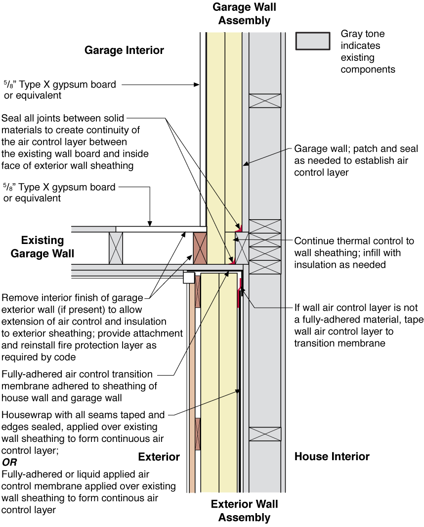
    Interior Garage Wall to Exterior House Wall

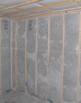
    Where the exterior wall of the house runs continuous past the garage interface, the interior wall finish of the perpendicular interfacing garage wall is cut back where it meets the house, exposing the stud cavity (Figure 1).  This allows the garage interior finish (typically gypsum board or lath and plaster) to be sealed to the framing and inside surface of the exterior wall sheathing to create the air control layer continuity.  The insulating sheathing is extended through the intersection to the exterior sheathing.  Once the rigid foam has been installed, a new interior finish (typically gypsum board) is installed over the insulating sheathing, and the perpendicular return walls are patched and finished.
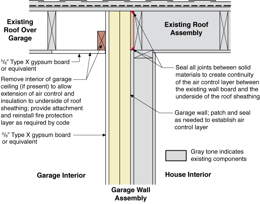
    Plan view (from above) showing how the existing garage wall gypsum board is cut away to air seal the shared wall before adding rigid foam insulation on the garage and exterior walls of the home.
    Figure 1. Plan view (from above) showing how the existing garage wall gypsum board is cut away to air seal the shared wall before adding rigid foam insulation on the garage and exterior walls of the home.


    Garage Wall to Roof

    Where the garage roof is shared with the roof of the house (Figure 2), or the exterior wall is run past the garage roof (Figure 3), the wall air control layer and insulation is extended up to the underside of the roof sheathing (Figure 2).  In order to create continuity of the air control layer, a portion of the garage ceiling gypsum board is removed (if present) and any gaps between the top of the garage wall interior finish (typically gypsum board or lath and plaster) are blocked (with additional gypsum board or other rigid material) and sealed.  The insulating sheathing is extended to the underside of the roof sheathing, and a new interior finish (typically gypsum board) is installed over the insulating sheathing.  If needed, the ceiling is patched and finished.

    Side view showing how existing wall is air sealed prior to installing rigid foam insulation on the garage side of the shared garage wall and roof of an existing home.
    Figure 2. Side view showing how existing wall is air sealed prior to installing rigid foam insulation on the garage side of the shared garage wall and roof of an existing home.


    Side view showing how existing garage wall and ceiling are air sealed prior to installing rigid foam insulation on the garage side of the shared wall of an existing home.
    Figure 3. Side view showing how existing garage wall and ceiling are air sealed prior to installing rigid foam insulation on the garage side of the shared wall of an existing home.


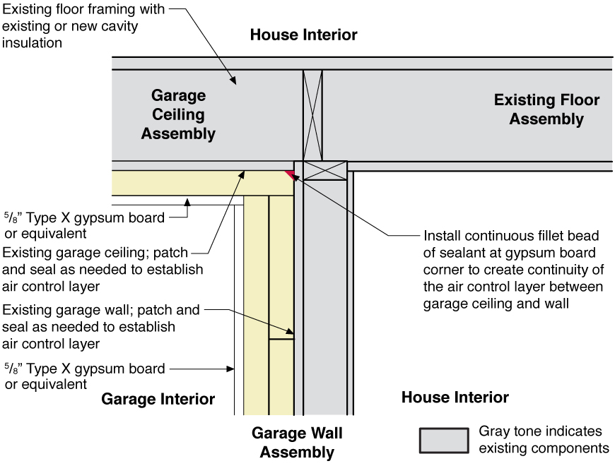
    Garage Wall to Floor Above

    Where there is a room located above the garage, the shared wall interfaces with the floor of the room above (Figure 4) and the air control layer and insulation of the wall is connected to the air control layer of the floor/ceiling assembly. (See Insulating Existing Floors over Garage for additional information on assembly options.)  In the detail provided below, the interior finish of the wall is connected to the interior finish of the ceiling.  The insulating wall and ceiling sheathing are installed over the existing wall and ceiling finishes and are continuous. A new interior finish (typically gypsum board) is installed over the insulating sheathing on both the wall and the ceiling. 

    Side view showing air sealing and rigid foam insulation installed over existing wall and ceiling under a room above, then covered with new gypsum board.
    Figure 4. Side view showing air sealing and rigid foam insulation installed over existing wall and ceiling under a room above, then covered with new gypsum board.


    How to Insulate the Wall between the House and the Garage

    1. Provide a continuous air control layer at the garage wall. Apply a continuous bead of sealant at the connection between the air control layer of the garage wall and the air control layer of the garage ceiling.  If needed, install an infill strip of gypsum board or other rigid material and seal the joints between the solid materials to complete the air control layer of the garage wall.
    2. Remove the interior finish material (e.g., gypsum board; lath and plaster) at the inside corner(s) of the perpendicular garage walls where they interface with the shared wall to allow extension of the air control and insulation to the exterior sheathing. 
    3. Seal the joints between solid materials to provide air sealing between the existing finish material (e.g., gypsum board; lath and plaster) and the inside face of the exterior wall sheathing.
    4. Install rigid insulating sheathing (foil-faced polyisocyanurate, XPS or EPS Type II) with joints offset horizontally and vertically and the joints of the outermost layer taped.
    5. Provide attachment/blocking and reinstall the fire protection layer (5/8” Type X gypsum board or equivalent) as required by the current adopted building code.
    Success
    Ensuring Success

    Ensure the air control layer is continuous at the separation between the living space and the garage.

    Seal all the connections and joints between the wall and ceiling air control layers.

    Maintain a proper ratio of vapor-impermeable to vapor-permeable insulation (see the Climate tab).

    Climate
    Climate

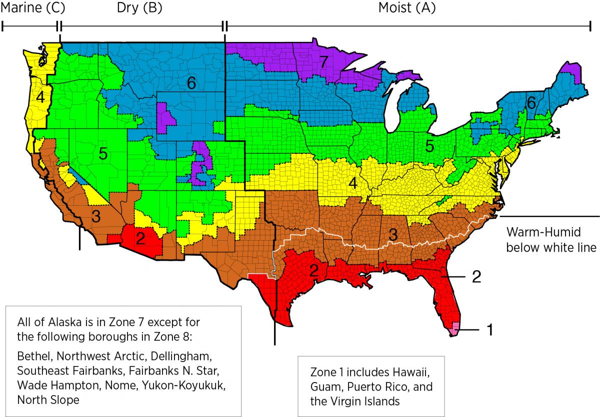
    The exterior wall assembly should be designed for a specific hygrothermal region, rain exposure zone, and interior climate. 

    The map in Figure 1 shows the climate zones for states that have adopted energy codes equivalent to the International Energy Conservation Code (IECC) 2009, 12, 15, and 18. The map in Figure 2 shows the climate zones for states that have adopted energy codes equivalent to the IECC 2021. Climate zone-specific requirements specified in the IECC are shown in the Compliance Tab of this guide. 

    IECC climate zone map.
    Figure 1 Climate Zone Map from IECC 2009, 12, 15, and 18. (Source: 2012 IECC)


    Climate Zone Map from IECC 2021.
    Figure 2. Climate Zone Map from IECC 2021. (Source: 2021 IECC)


    The insulation levels should be based on the minimum requirements for vapor control in the current adopted building code and the minimum requirements for thermal control in the current energy code. Additional insulation can be added above these minimums to create high R-Value exterior wall assemblies. The table below provides the minimum thermal resistance (R-value) requirements for exterior walls specified in the 2009 IECC (ICC 2009b) and the 2012 IECC (ICC 2012b), based on climate zone.

    Minimum R-Value Requirements for exterior walls in the 2009 and 2012 IECC.
    Table 1. Minimum R-Value Requirements for exterior walls in the 2009 and 2012 IECC.


    Compliance

    Compliance

    The Compliance tab contains both program and code information. Code language is excerpted and summarized below. For exact code language, refer to the applicable code, which may require purchase from the publisher. While we continually update our database, links may have changed since posting. Please contact our webmaster if you find broken links.


    ENERGY STAR Single-Family New Homes, Version 3/3.1 (Rev. 11)

    ENERGY STAR Single-Family New Homes requires that ceiling, wall, floor, and slab insulation levels meet or exceed those specified in the 2009 International Energy Conservation Code (IECC) with some alternatives and exceptions, and achieve Grade 1 installation per RESNET Standards (see 2009 and 2012 IECC Code Level Insulation – ENERGY STAR Requirements and Insulation Installation (RESNET Grade 1). If the state or local residential building energy code requires higher insulation levels than those specified in the 2009 IECC, you must meet or exceed the locally mandated requirements. Some states have adopted the 2012 or 2015 IECC. Visit the U.S. DOE Building Energy Codes Program to see what code has been adopted in each state.

    National Rater Design Review Checklist

    3. High-Performance Insulation.
    3.1 Specified ceiling, wall, floor, and slab insulation levels comply with one of the following options:
    3.1.1 Meets or exceeds 2009 IECC levels5, 6, 7 OR;
    3.1.2 Achieves ≤ 133% of the total UA resulting from the U-factors in 2009 IECC Table 402.1.3, per guidance in Footnote 5d, AND specified home infiltration does not exceed the following:6, 7

    • 3 ACH50 in CZs 1, 2
    • 2.5 ACH50 in CZs 3, 4
    • 2 ACH50 in CZs 5, 6, 7
    • 1.5 ACH50 in CZ 8

    Footnote 5) Specified levels shall meet or exceed the component insulation levels in 2009 IECC Table 402.1.1. The following exceptions apply:
    a. Steel-frame ceilings, walls, and floors shall meet the insulation levels of 2009 IECC Table 402.2.5. In CZ 1 and 2, the continuous insulation requirements in this table shall be permitted to be reduced to R-3 for steel-frame wall assemblies with studs spaced at 24 in. on center. This exception shall not apply if the alternative calculations in d) are used;
    b. For ceilings with attic spaces, R-30 shall satisfy the requirement for R-38 and R-38 shall satisfy the requirement for R-49 wherever the full height of uncompressed insulation at the lower R-value extends over the wall top plate at the eaves. This exemption shall not apply if the alternative calculations in d) are used;
    c. For ceilings without attic spaces, R-30 shall satisfy the requirement for any required value above R-30 if the design of the roof / ceiling assembly does not provide sufficient space for the required insulation value. This exemption shall be limited to 500 sq. ft. or 20% of the total insulated ceiling area, whichever is less. This exemption shall not apply if the alternative calculations in d) are used;
    d. An alternative equivalent U-factor or total UA calculation may also be used to demonstrate compliance, as follows: An assembly with a U-factor equal or less than specified in 2009 IECC Table 402.1.3 complies. A total building thermal envelope UA that is less than or equal to the total UA resulting from the U-factors in Table 402.1.3 also complies. The performance of all components (i.e., ceilings, walls, floors, slabs, and fenestration) can be traded off using the UA approach. Note that Items 3.1 through 3.3 of the National Rater Field Checklist shall be met regardless of the UA tradeoffs calculated. The UA calculation shall be done using a method consistent with the ASHRAE Handbook of Fundamentals and shall include the thermal bridging effects of framing materials. The calculation for a steel-frame envelope assembly shall use the ASHRAE zone method or a method providing equivalent results, and not a series-parallel path calculation method.

    Footnote 6) Consistent with the 2009 IECC, slab edge insulation is only required for slab-on-grade floors with a floor surface less than 12 inches below grade. Slab insulation shall extend to the top of the slab to provide a complete thermal break. If the top edge of the insulation is installed between the exterior wall and the edge of the interior slab, it shall be permitted to be cut at a 45-degree angle away from the exterior wall. Alternatively, the thermal break is permitted to be created using ≥ R-3 rigid insulation on top of an existing slab (e.g., in a home undergoing a gut rehabilitation). In such cases, up to 10% of the slab surface is permitted to not be insulated (e.g., for sleepers, for sill plates). Insulation installed on top of slab shall be covered by a durable floor surface (e.g., hardwood, tile, carpet).

    Footnote 7) Where an insulated wall separates a garage, patio, porch, or other unconditioned space from the conditioned space of the house, slab insulation shall also be installed at this interface to provide a thermal break between the conditioned and unconditioned slab. Where specific details cannot meet this requirement, partners shall provide the detail to EPA to request an exemption prior to the home’s certification. EPA will compile exempted details and work with industry to develop feasible details for use in future revisions to the program. A list of currently exempted details is available at: energystar.gov/slabedge.

    National Rater Field Checklist

    Thermal Enclosure System.
    1. High-Performance Fenestration & Insulation.
    1.3 All insulation achieves Grade I install. per ANSI / RESNET / ICC Std. 301. Alternatives in Footnote 5.5, 6

    Footnote 5) Two alternatives are provided: a) Grade II cavity insulation is permitted to be used for assemblies that contain a layer of continuous, air impermeable insulation ≥ R-3 in Climate Zones 1 to 4, ≥ R-5 in Climate Zones 5 to 8; b) Grade II batts are permitted to be used in floors if they fill the full width and depth of the floor cavity, even when compression occurs due to excess insulation, as long as the R-value of the batts has been appropriately assessed based on manufacturer guidance and the only defect preventing the insulation from achieving Grade I is the compression caused by the excess insulation.

    Footnote 6) Ensure compliance with this requirement using ANSI / RESNET / ICC Std. 301 including all Addenda and Normative Appendices, with new versions and Addenda implemented according to the schedule defined by the HCO that the home is being certified under, with approved exceptions listed at www.energystar.gov/ERIExceptions.

    2. Fully-Aligned Air Barriers 7 - At each insulated location below, a complete air barrier is provided that is fully aligned as follows:
    Ceilings: At interior or exterior horizontal surface of ceiling insulation in Climate Zones 1-3; at interior horizontal surface of ceiling insulation in Climate Zones 4-8. Also, at exterior vertical surface of ceiling insulation in all climate zones (e.g., using a wind baffle that extends to the full height of the insulation in every bay or a tabbed baffle in each bay with a soffit vent that prevents wind washing in adjacent bays). 8
    Walls: At exterior vertical surface of wall insulation in all climate zones; also at interior vertical surface of wall insulation in Climate Zones 4-8.9
    Floors: At exterior vertical surface of floor insulation in all climate zones and, if over unconditioned space, also at interior horizontal surface including supports to ensure alignment. Alternatives in Footnotes 12 & 13.11, 12, 13
    2.6 Floors above garages, floors above unconditioned basements or crawlspaces, and cantilevered floors.
    2.7 All other floors adjoining unconditioned space (e.g., rim / band joists at exterior wall or at porch roof).

    Footnote 7) For purposes of this Checklist, an air barrier is defined as any durable solid material that blocks air flow between conditioned space and unconditioned space, including necessary sealing to block excessive air flow at edges and seams and adequate support to resist positive and negative pressures without displacement or damage. EPA recommends, but does not require, rigid air barriers. Open-cell or closed-cell foam shall have a finished thickness ≥ 5.5 in. or 1.5 in., respectively, to qualify as an air barrier unless the manufacturer indicates otherwise. If flexible air barriers such as house wrap are used, they shall be fully sealed at all seams and edges and supported using fasteners with caps or heads ≥ 1 in. diameter unless otherwise indicated by the manufacturer. Flexible air barriers shall not be made of kraft paper, paper-based products, or other materials that are easily torn. If polyethylene is used, its thickness shall be ≥ 6 mil.

    Footnote 8) All insulated ceiling surfaces, regardless of slope (e.g., cathedral ceilings, tray ceilings, conditioned attic roof decks, flat ceilings, sloped ceilings), must meet the requirements for ceilings.

    Footnote 9) All insulated vertical surfaces are considered walls (e.g., above and below grade exterior walls, knee walls) and must meet the air barrier requirements for walls. The following exceptions apply: air barriers recommended, but not required, in adiabatic walls in multifamily dwellings; and, in Climate Zones 4 through 8, an air barrier at the interior vertical surface of insulation is recommended but not required in basement walls or crawlspace walls. For the purpose of these exceptions, a basement or crawlspace is a space for which ≥ 40% of the total gross wall area is below-grade.

    Footnote 11) EPA highly recommends, but does not require, an air barrier at the interior vertical surface of floor insulation in Climate Zones 4-8.

    Footnote 12) Examples of supports necessary for permanent contact include staves for batt insulation or netting for blown-in insulation. Alternatively, supports are not required if batts fill the full depth of the floor cavity, even when compression occurs due to excess insulation, as long as the R-value of the batts has been appropriately assessed based on manufacturer guidance and the only defect preventing the insulation from achieving the required installation grade is the compression caused by the excess insulation.

    Footnote 13) Alternatively, an air barrier is permitted to be installed at the exterior horizontal surface of the floor insulation if the insulation is installed in contact with this air barrier, the exterior vertical surfaces of the floor cavity are also insulated, and air barriers are included at the exterior vertical surfaces of this insulation.

    Please see the ENERGY STAR Single-Family New Homes Implementation Timeline for the program version and revision currently applicable in your state.


    DOE Zero Energy Ready Home (Revision 07)

    The DOE Zero Energy Ready Home Program is a voluntary high-performance home labeling program for new homes operated by the U.S. Department of Energy. Builders and remodelers who are conducting retrofits are welcome to seek certification for existing homes through this voluntary program.

    Exhibit 1 Mandatory Requirements.
    Exhibit 1, Item 1) Certified under the ENERGY STAR Qualified Homes Program or the ENERGY STAR Multifamily New Construction Program.
    Exhibit 2, Item 2) Ceiling, wall, floor, and slab insulation shall meet or exceed 2015 IECC levels and achieve Grade 1 installation, per RESNET standards.


    2009-2021 IECC and IRC Insulation Requirements Table

    The minimum insulation requirements for ceilings, walls, floors, and foundations in new homes, as listed in the 2009, 2012, 2015, 2018, and 2021 IECC and IRC, can be found in this table


    200920122015, 2018, and 2021 International Energy Conservation Code (IECC)

    Section R402.4 Air leakage (Mandatory).

    Section R402.4.1 Building Thermal Envelope.

    Section R402.4.5 Recessed lighting.

    Table R402.4.1.1 (R402.4.2 in 2009 IECC) Air Barrier and Insulation Installation and Component Criteria

    Retrofit:  2009, 2012, 2015, 2018,  and 2021 IECC

    Section R101.4.3 (in 2009 and 2012). Additions, alterations, renovations, or repairs shall conform to the provisions of this code, without requiring the unaltered portions of the existing building to comply with this code. (See code for additional requirements and exceptions.)

    Chapter 5 (in 2015, 2018, 2021). The provisions of this chapter shall control the alteration, repair, addition, and change of occupancy of existing buildings and structures.


     200920122015, 2018, and 2021 International Residential Code (IRC)

    Section R302.5 Dwelling/garage opening/penetration protection.

    Section R302.6 Dwelling/garage fire separation.

    Table R302.6 Dwelling/Garage Separation.

    Section R315.3 Carbon Monoxide Alarms where required in existing dwellings. ("Location" in 2015, 2018, and 2021 IRC)

    Table 702.3.5 Minimum thickness and application of gypsum board.

    Section N1102.4 Air leakage (Mandatory).

    Section N1102.4.1 Building Thermal Envelope.

    Table N1102.4.1.1 Air Barrier and Insulation Installation

    Retrofit:  2009, 2012, 2015, 2018,  and 2021 IRC

    Section R102.7.1 Additions, alterations, or repairs. Additions, alterations, renovations, or repairs shall conform to the provisions of this code, without requiring the unaltered portions of the existing building to comply with the requirements of this code, unless otherwise stated. (See code for additional requirements and exceptions.)

    Appendix J regulates the repair, renovation, alteration, and reconstruction of existing buildings and is intended to encourage their continued safe use.

    More

    More Info.

    Access to some references may require purchase from the publisher. While we continually update our database, links may have changed since posting. Please contact our webmaster if you find broken links.

    References and Resources*
    Author(s)
    Pettit,
    Neuhauser,
    Gates
    Organization(s)
    Building Science Corporation,
    BSC
    Publication Date
    Description
    Guidebook providing useful examples of high performance retrofit techniques for the building enclosure of wood frame residential construction in a cold and somewhat wet climate.
    *For non-dated media, such as websites, the date listed is the date accessed.
    Contributors to this Guide

    The following authors and organizations contributed to the content in this Guide.

    Building Science Corporation, lead for the Building Science Consortium (BSC), a DOE Building America Research Team

    Sales
    Building Science Measures
    Building Science-to-Sales Translator

    High-R Wall Insulation = High-Efficiency or Ultra-Efficient Wall Insulation

    Image(s)
    Technical Description

    There are two levels of wall insulation: high-efficiency insulation, which meets the 2015 International Energy Conservation Code, and ultra-efficient insulation, which is 25% more efficient than this national code. Using high-efficiency and ultra-efficient insulation along with professional installation (e.g., no gaps, voids, compression, or misalignment with air barriers, complete air barriers, and minimal thermal bridging) creates conditioned spaces that require very little heating and cooling, along with even comfort and quiet throughout the house.

    High-Efficiency or Ultra-Efficient Wall Insulation
    Sales Message

    High-efficiency wall insulation helps provide added thermal protection. What this means to you is less wasted energy along with enhanced comfort and quiet. Knowing there is one opportunity to optimize performance during construction, wouldn’t you agree it’s a great opportunity to meet or exceed future codes?

    Last Updated

    Mobile Field Kit

    The Building America Field Kit allows you to save items to your profile for review or use on-site.

    Sign Up  or  Log In

    Did you find this information helpful?

    If you have questions and/or would like a reply to this feedback, please include your e-mail address in the message.
    This question is for testing whether or not you are a human visitor and to prevent automated spam submissions.