

Scope
Heating contractors or building superintendents, use this guide to improve the distribution of heat in a one-pipe steam system in existing low-rise multi-family residential buildings and to enable the system to operate at the low pressures required for one-pipe thermostatic radiator valves (TRVs) to work better for improved temperature control and energy savings. Improve system performance by doing the following:
- Install master vents on the mains and risers to let out air that is trapped in the pipes and preventing steam from reaching its destination (known as air binding).
- Dry out the steam, so the master vents don’t squirt water.
- Make less steam, by enabling modulation and maximizing turndown
- Install a low-range pressure control.
For more on hydronic heating (hot water and steam), see the U.S. Department of Energy’s Standard Work Specifications.
See the Compliance Tab for links to related codes and standards and voluntary federal energy-efficiency program requirements.
Description
Air fills the pipes and radiators when a steam cycle ends. When the boiler starts again, the expanding steam must push the air out so that steam can reach the radiators. Air purging is one of the central challenges in balancing a steam system. Air in the main and riser piping blocks the passage of steam and improper venting traps it in place. This phenomenon is referred to as “air binding.” The farther an apartment is from the boiler, the longer it takes the air to be vented from the supply pipes and the longer the steam delivery is delayed. In building locations farthest from the boiler (top floors, certain apartment lines), air binding can result in underheating. Poor balance will be evident from complaints of localized underheated and overheated areas and/or open windows nearest the boiler during the heating season. Building owners are typically required to provide a minimum amount of heat to multifamily buildings. This may be regulated via one or more laws or codes.
With unbalanced steam systems, owners are often forced to overheat most of the building in order to provide sufficient heat to a handful of underheated areas. After balancing the steam distribution, owners will be able to comply with minimum heat regulations without overheating.
Most steam systems have vents that are too small; many systems lack vents entirely. The solution is to install very-high-capacity air vents at the ends of the mains and at the tops of the risers. This approach was proposed by Frank Gerety in One Pipe Steam Heating: The Gospel of Dry Steam in 1986. Dan Holohan also refers to it in his popular The Lost Art of Steam Heating.
Air binding exemplifies coal’s legacy. Coal fires built slowly and ran all day so systems were installed with slow, low-capacity vents because a gradual venting of air at start-up was sufficient. Conversely, systems fired on oil and gas run at full fire from the start, and they cycle on and off repeatedly throughout the day. Air has to be vented rapidly and repeatedly, hence the need to install large vents in place of the original small ones.
Master venting is needed to address the air binding, but implementing master venting without control of the boiler can be problematic. If the boiler is the proper size and properly controlled, then the new, larger vents will be silent, because there is less airflow restriction. The vents can be intolerably loud when the boiler is too large or poorly controlled, and the vents can even squirt water if the boiler is making wet steam.
Many heating firms prefer to work solely on the boiler itself. But the boiler is just one part of the heating system and meaningful savings cannot be achieved with such a narrow focus. Determining the needed work scope means leaving the boiler room and addressing the steam distribution system.
How to Assess the Steam Distribution System
1. Go to the Roof
First, go to the roof. This makes it easy to see the shape and layout of the building, which will help you to locate the steam mains.
Is the building U-shaped? H-shaped? Make a simple sketch of the building outline. (If the building manager can provide a floor plan, feel free to use that instead.) On this outline, show where the chimney, elevator bulkhead, and vent stacks are. These building components go straight down to the basement, so showing them in the drawing will makes it easier to stay oriented while in the basement tracing the mains.
2. Inspect the Top-Floor Apartments
After visiting the roof, go into the apartments on the top two floors. Check for several things:
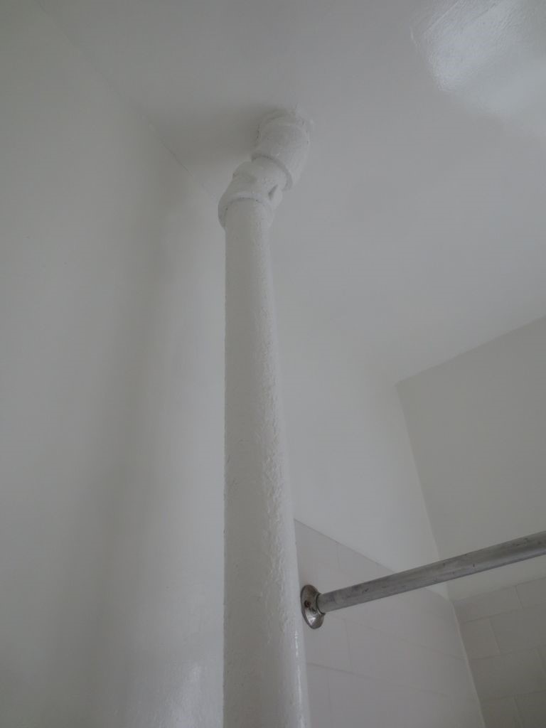
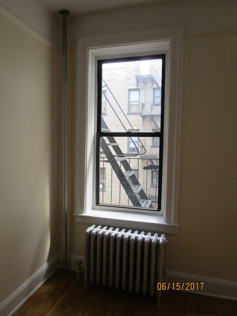
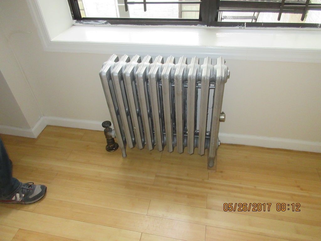
- Are all the risers exposed or just the direct-heat risers (those bare pipes in the bathrooms and kitchens, as shown in Figure 1)?
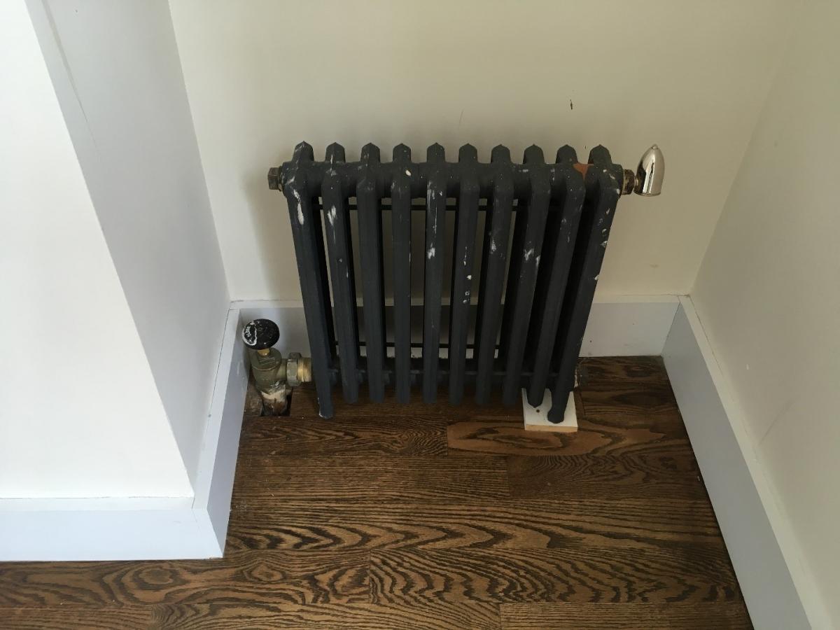
- If the risers are exposed (as shown in Figure 2), do they all have vents? Or do just the direct-heat risers have vents?
- What kind of air vents do they have, fast or slow? If in doubt, manufacturer data can help determine this, but in general, the larger the opening, the faster the vent.
- Are there signs of water leaking from them?
3. Walk the Basement
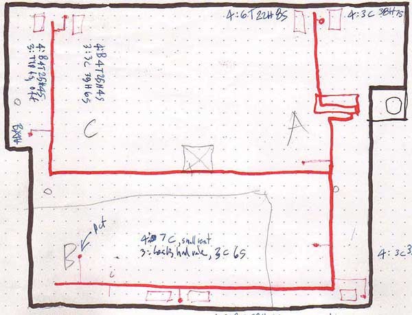
After visiting upper-floor apartments, go to the basement. Trace out the steam mains, starting from the boiler room and going out to the end of each main. Draw the mains on the building outline sketch you started while on the roof. You may want to use a red pen for supply lines and a blue pen for any returns (Figure 4).
4. Determine the Main Line Vent Locations
Main line venting must be generous, but doesn’t have to be precise. The goal is to put clusters of fast vents near the ends of the largest mains. In a six-family building with a single steam-main running down the middle of the basement, the only main-line vent needed will be at the end of that single steam main. Larger buildings typically need the mains to be vented at three to five locations.
Here are some suggestions for where and where not to locate the main vents:
- Pay special attention to building areas that get poor heat and be sure to vent there.
- Don’t worry about smaller branch lines.
- It’s best not to install vents at the ends of long dry returns. Instead, put the vents near the last takeoff from the supply main.
- Do NOT install vents into electric rooms. Make the connection in an adjacent room, or run the connection out through the wall.
Piping Details for Main Line Vents
Connection Types
Vent connections can be made by cutting in fittings, by welding on weld-o-lets, or by drilling and tapping. Of the three methods, drilling and tapping is often the most cost-effective. It is under-utilized by most plumbers. Experience has shown that there is little danger of tappings leaking at routine steam pressures.
Best Spots to Connect Main Line Vents
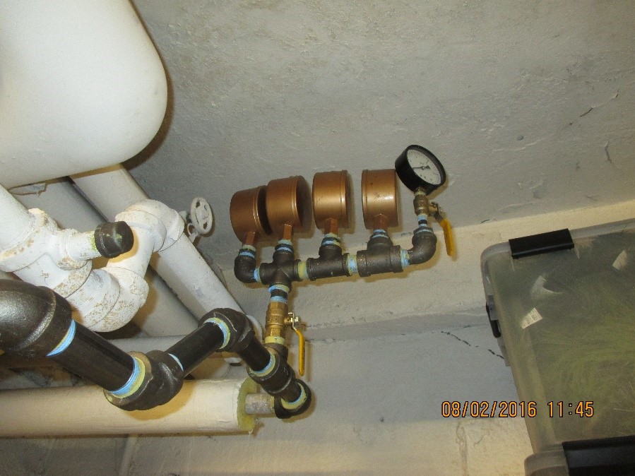
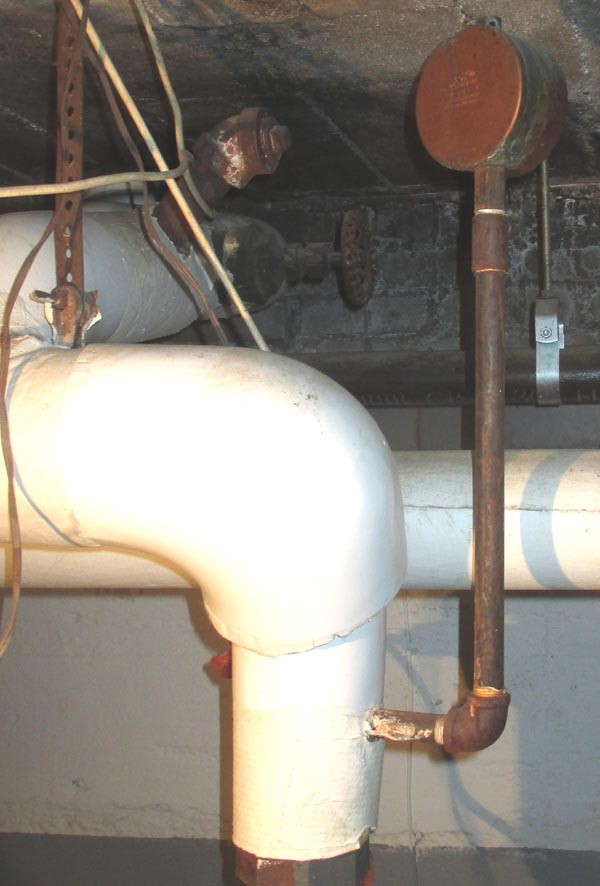
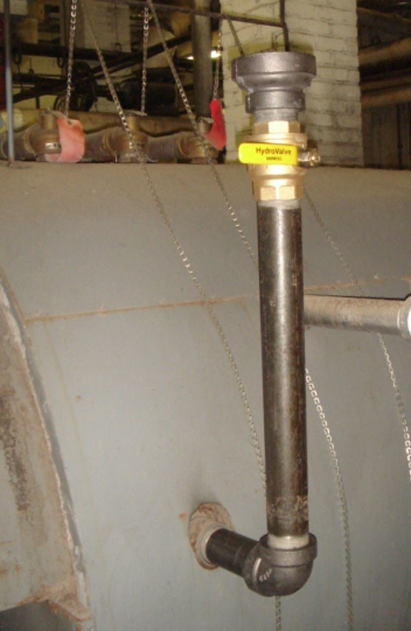
Vents do not need to be installed directly onto the steam main. They can be installed onto branch pipes that connect near the end of the main. They can also be installed onto drip piping that is 1¼” and larger, as shown in Figure 5.
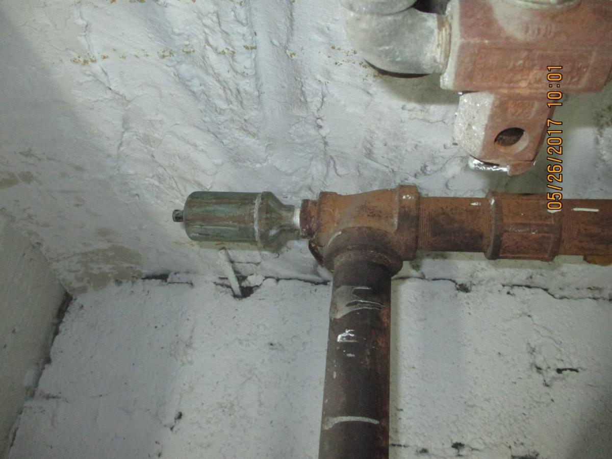
Vents can even be installed onto the sides of drip legs as shown in Figure 6.
But do NOT install vents on top of a drip leg as shown in Figure 7 or they will be corroded by water droplets.
General Principles for Piping Main Line Vents
- When detailing vent connections, the goal is to prevent spitting. Water must be kept away from the vent, and the vents must drain.
- Keeping the piping full size right up to the vents helps; so does installing the vents as high as possible on the main line.
- Avoid adding horizontal piping. Come off the top of the steam pipe if possible; otherwise, come off at 45° above horizontal.
- Water can splash back from elbows, so wherever possible install vent connections at least 18” away from the nearest elbow.
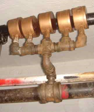
- When ganging vents, the common piping should be minimum ¾”.
- If installing onto a drip leg, make the connection near the top of the leg, on a side, using a close nipple, then pipe up as high as possible.
Main Line Vent Sizing
The bigger the mains, the more vents they need. The chart below shows how many vents should be installed based on the total volume of the steam mains being vented. (Note: different models of vents may be used, after adjusting for the different venting rates.)
Large mains typically divide up into a few smaller ones. The vents go at the ends of the smaller mains, but there needs to be enough of them to vent all the air in the large common piping as well. The calculations do not need to be precise, just generous. Master vents cannot be too large.

Riser Venting
- Virtually any building three stories and up should get riser vents. They can be skipped in buildings without vertical imbalance, but those are rare.
- In downfeed systems, the riser vents go in the basement, but again those systems are rare.
- Riser venting is harder than main line venting. Not only does the work have to be done in occupied spaces, but there are many more risers than steam mains.
- If the risers are exposed, the best way to add a vent is to drill and tap the riser. Do this near the ceiling, on the floor just below the top floor (unless the risers go all the way up through the top floor, which is rare).
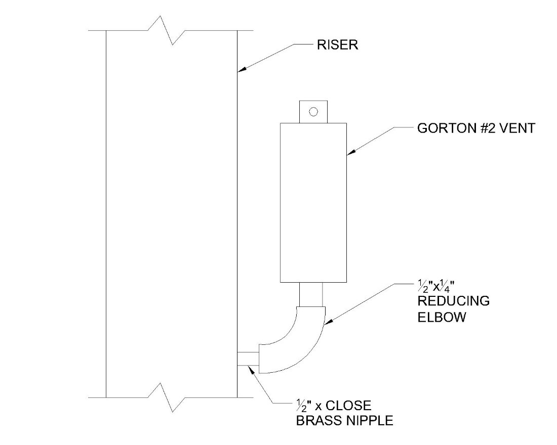
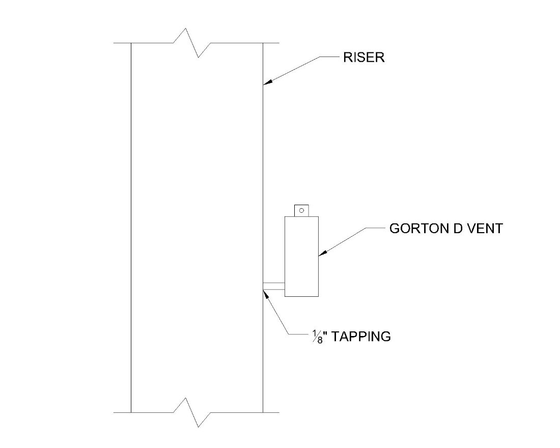
- Vents comparable to Gorton #D or #1 are sufficient for systems up to six floors. In taller buildings, vents comparable to a Gorton #2 should be used. Figures 8 and 9 show how these can be piped.
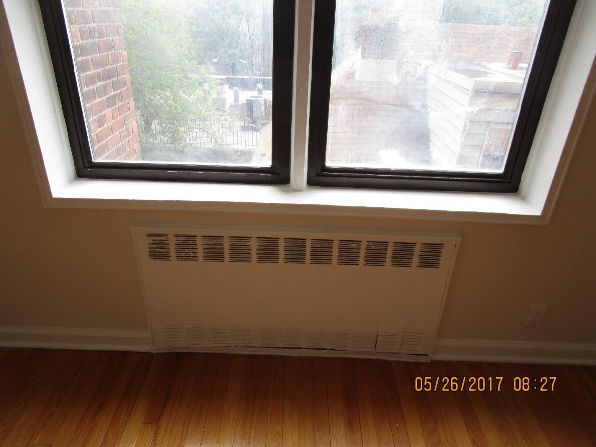
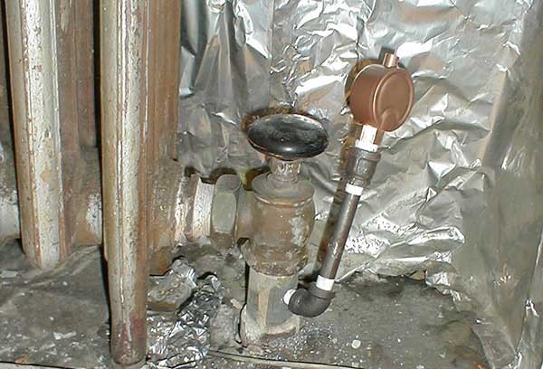
The work is much trickier when the risers are buried inside the walls. If the top-floor heaters are enclosed, it is sometimes practical to drill and tap the stub-out just below the hand-valve as shown in Figure 10.
If none of those options are viable or affordable, the only real option may be to put the fast vents, such as those recommended above, directly onto the top floor radiators.
Radiator Vents
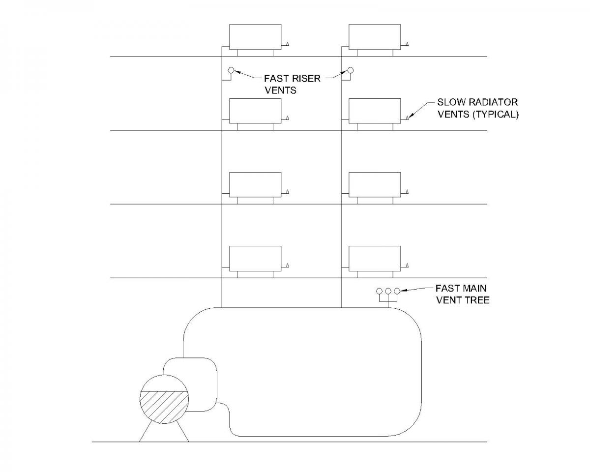
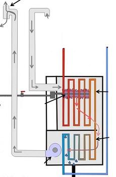
Radiator vents should be slow models, such as a Hoffman 40s or 41s. This will help balance the system and prevent overheating. With slow vents on the radiators, the steam will first flow towards the fast vents at the ends of the mains and risers and only then start filling the radiators. The goal is for all the radiators in the building to start filling with steam at about the same time, no matter how far away from the boiler they are. This makes for much more even heat. In this way, small radiator vents combine with large master vents to balance the steam distribution; see Figure 11 for a simplified schematic.
Radiator Vent Location
Make sure the heaters have their air vents mounted low, usually about a third of the way up from the bottom (see Figures 12 and 13). This allows more steam to fill the radiator before the vent shuts.
Dry Steam
Dry steam, which is steam that contains few entrained water droplets, is needed for all steam systems and is a critical part of successful steam balancing. If the boiler is making wet steam, water can leak from the master vents and cause property damage. Water can also accumulate at the ends of steam mains and block steam from reaching certain lines or apartments.
There are four low-cost measures that can improve steam quality:
Limit High Fire
The faster the steam leaves the boiler, the more water it carries along with it. Limiting high fire reduces the maximum exit velocity and this associated carryover.
Many burners have the ability to reduce their high fire rate while in automatic modulation mode; these are straightforward. But one common manufacturer forces a choice—the controls on Industrial Combustion (IC) burners disable automatic modulation when limiting fire. This lack of modulation increases cycling and reduces efficiency, and it can make it impossible to maintain steady low pressure, which many steam systems need.
For IC burners, a solution is to install a 135-ohm variable resistor into the drive-open leg running to the modulating motor. Note: do NOT mount the resistor inside the burner control cabinet or the burner may lose its UL rating. Instead, add a box wherever it can be securely mounted and route the modulation wiring through it. Label the box clearly.
If the burner was already running at limited fire, it’s reasonable to match that firing rate. Otherwise, 80% is a good starting point. There is no downside to limiting high fire so long as the boiler is able to make steam pressure.
Clean the Boiler Water
A common cause of wet steam is oily stuff in the boiler water. It gets in pretty much any time piping work is done on the system. The oil can’t be seen and it’s not easy to detect. Assume there’s oil in the water after piping work was done or if wet steam is a known issue. If the piping work is done in summer, it is best to wait until fall to do this cleaning. Once the heat starts, oil can take a week or two to work its way down from the radiators to the boiler.
Skimming Boilers
Skimming is a long-established method of removing oil from boiler water. The goal is to skim the surface of heated but calm water. Getting the boiler hot (but not steaming) loosens up the oil. The loose oil gathers on the surface of the water. The water needs to be calm (not boiling), or the oil will mix back in with the water rather than laying on top of it.
To be effective, the skim tapping drain needs to be at the water surface or just above it. It also needs to be big. Pipe full size from the skim tapping and don’t reduce until at least a foot below the elbow.
To skim, fire the boiler until it just makes steam, then turn off the burner. (The boiler will stay hot enough to make domestic hot water). Fully open the skim drain, then open the manual feed valve. (If there is no manual feed valve, run some temporary wiring to make the condensate unit do the same thing). Adjust the feed valve as needed so that the water level is no higher than halfway up the skim tapping. After a few hours, close the valves and drain the boiler to its normal water line. Immediately fire the burner to drive the oxygen out of the fresh water. Make sure the boiler gets steam-hot.
Detergent Cleaning
It’s a good idea to follow a skimming with a detergent cleaning, especially on new boilers. The boiler manufacturer may have a list of approved products and methods for this. But often the simplest method is to use a dishwasher detergent that contains an anti-foaming agent, such as Cascade, which will prevent suds in the boiler. The anti-foaming agent will start to break down after about a week, so the boiler-water must be drained out after a few days. Use unscented detergent, or the entire building will smell like lemon. As a very rough rule of thumb, use one ounce of detergent powder per three boiler horsepower.
For a pumped return system, the easiest way to add detergent is to pour it into the feed tank. If there’s no feed tank, the detergent can go directly into the boiler. On a steel boiler, remove a plug from the side of the boiler below the water line and pipe a port as shown in Figure 14.
If no plugs below the water line exist, a tapping above the waterline can be used, but to keep the detergent powder from sitting in the elbow, pipe a street elbow into the tapping, then pipe straight up. When adding detergent, pour some water in afterwards to clear the port.
Cast-iron boilers are harder because they have so few tappings. The best option may be to pour detergent in through the safety valve tapping. Pour in water as needed to rinse away all the powder before re-installing the safety valve. Do NOT add detergent through the control tree. The powder could sit in the piping and pigtails, possibly affecting the controls’ operation.
The detergent must be removed from the boiler after a few days or it will start making suds. To remove the detergent:
- Steel Boilers: Drain the boiler, then re-fill and drain it again to remove all traces of detergent.
- Cast-Iron Boilers: Care has to be taken to protect cast iron against thermal shock. Ideally, arrange for the boiler to be cold when you return to the job site to remove the detergent. If the boiler is needed for domestic hot water, ensure that the aquastat is set as low as possible. Add water, then do a series of partial fills and drain downs to prevent shock before doing a complete drain down.
In all cases, immediately fire the burner afterwards to drive the oxygen out of the fresh water. Make sure the boiler gets steam-hot.
A Special Word on Flux
If soldered copper is used for any piping in a steam system, use only water-soluble soldering paste flux. Standard flux is oil-based and sticky. It takes forever to get it out of a boiler.
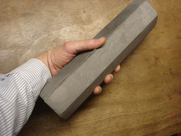
Anode Bars
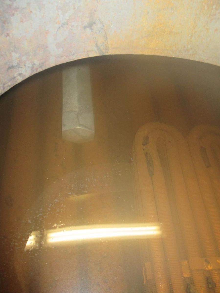
Excessive chemical water treatment causes carryover and wet steam. Fortunately there is an alternative: anode bars (see Figure 15), which work on the same principle as sacrificial anodes in water heaters. The anode bar is made of a metal like magnesium or aluminum that is more reactive than steel; when both metals are physically connected in water, the more reactive one will corrode faster, thus protecting the less reactive metal (in this case the boiler steel) from corroding.
Boiler anode bars typically need to be replaced annually and the cost is comparable to a year of chemical water treatment.
The bars are installed through the manhole and laid between the fire tubes (see Figure 16). (While the manhole is open, make sure the steam nozzle was trimmed or dry steam will be impossible.) If there’s no manhole, the bars can be sawed in half lengthwise and inserted through a hand-hole. Maximize contact between the bars and the tubes.
Large boilers need multiple bars. The anode bar manufacturer should be consulted for application guidance. Table 2 can be used as a rough rule of thumb for how many bars to install based on the boiler horsepower.

If the makeup water feeds into a receiver, it’s a good idea to also put a bar into the receiver so that some oxygen can be removed from the water even before it enters the boiler.
Anode bars probably shouldn’t be used in leaky systems, such as those with leaking buried pipes, overflowing receivers, or squirting air vents. If the daily makeup water exceeds 2% of a steam boiler's water content, the water loss should be corrected before switching to anode bars. Assume buried pipes are leaking unless a water-meter proves otherwise. If a system has no buried pipes, no receiver, and no squirting air vents, and the boiler has no internal leaks, the system can be assumed to be tight.
Anode bars cannot be used in cast-iron boilers. But cast-iron boilers in tight systems don't need anode bars or chemical water treatment. (In some areas they may need softened water, however.) Unlike steel, cast-iron forms an oxide coating that arrests further corrosion. But the oxide layer can’t protect against excessive makeup-water, so it’s essential to monitor water use and check for areas of likely water loss (especially buried returns).
Lower the Waterline
The open space inside a boiler at the top is crucial to making dry steam. This area, called the steam chest, is where water droplets fall out of the steam, rather than being carried into the system. The larger the steam chest, the drier the steam, and the lower the waterline, the larger the steam chest, so lowering the waterline helps make dry steam.
If a steel boiler doesn’t have a tankless coil, the casting mark on the water feeder/primary low water cutoff (LWCO) should be about ½” above the top-of-tubes. If there is a coil, set the waterline as low as it can be while still covering enough of the coil to make hot water.
For cast-iron boilers, follow the manufacturer’s recommendations. This will often give a much lower waterline than anticipated. For example, one manufacturer calls for the casting mark on the feed control to be 1½” above the bottom of the sight glass. This results in the largest steam chest possible, while still ensuring safety.
Maximizing Low Fire
Full Turndown
Full turndown is crucial for efficiency. Poor turndown increases cycling and can make it impossible to maintain the steady low steam pressure that steam systems need. The goal is to get the lowest low fire possible, low enough that the boiler never shuts off on pressure. This enables the boiler to maintain a steady head of low pressure steam for the entire heat cycle.
Confirm Low-Fire Rate
Note the manufacturer’s low-fire rate listed on the burner nameplate. Then check the actual low-fire rate as follows:
Gas Burners: Clock the gas meter while the burner runs on low fire. Let the meter run for several rotations, then calculate the firing rate using this formula:
(Total Cubic Feet) x 3,600 ÷ (Total Seconds) = MBH
To get an accurate reading on rotary gas meters, keep the timer running for several dial rotations and do the calculation for the total reading.
Pressure-Atomized Oil Burners: Read the gauge indicating oil pressure to the nozzle. Install one if necessary. Then use a nozzle rating chart to determine the firing rate.
Air-atomized oil burners: It is not possible to directly verify the firing rates on these burners without installing an oil meter. Instead, confirm that the oil metering device (pump or valve) is going through its full range of motion. Where applicable, read the metering pump model and pin size. Compare to the manufacturer’s charts to determine the firing rate.
Check Everything
Work with the burner technician to get the low fire as low as possible while providing dependable operation. This may require them to confirm the gas regulator, oil nozzle size and pressure, metering pump, and draft control.
Low Range Pressure Control
Once the master venting is in place and the low-fire rate has been minimized, it’s good practice to install a pressure control that's accurate at low pressure. One common option is a Vaporstat. Not only do Vaporstats facilitate low-pressure operation, they prevent technicians from boosting the steam pressure.
Steam Outlet and Near Boiler Piping
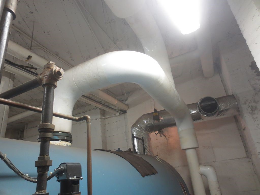
The size of the boiler outlet and the design of the near boiler piping (also known as the header piping) also have a big impact on steam quality. If the steam outlet is too small, the high exit velocity of the steam will carry water droplets along with it — hence the benefit of limiting high fire as discussed above. Additionally, the near boiler piping must provide a path for the water droplets that do carry over to return directly back to the boiler and not enter the distribution. This separation is achieved via momentum.
One traditional example is shown above in Figure 17. The lighter steam is able to make a quick turn up to the building, while the heavier water droplets continue on and head back down to the boiler through the equalizer.
Re-piping a header can be very expensive and changing the size of a steam outlet even more so. It is very important to get these details correct on new boiler installations. However, for most retrofit projects, the four measures listed above are the most cost-effective options for improving steam quality.
Backpitched Piping
Backpitched steam mains can create low spots where water collects. These often cause water hammer, especially at the start of a heating cycle. This hammer can destroy main-line vents, so be sure to correct such conditions before installing vents.
Controls
In most steam systems, the heating control does not know what is happening in the apartments. It operates based on outdoor temperature; the colder it gets, the longer the boiler runs. This indirect mechanism is inherently inaccurate and prone to overheating the building. In order to achieve any energy and cost reductions from improvements to the heating system (or other energy-efficiency improvements like adding air sealing and insulation), it is critical that the control be smart enough to understand that the load has been reduced.
One proven way to close that feedback loop is to install a new heating control that responds to temperature sensors installed in a representative sample of apartments. Smaller buildings can use off-the-shelf components while larger ones may require a more customized solution. In most cases the temperature sensors are wireless, which simplifies installation.
These controls can include warm-weather shutdown and nighttime setback features to optimize efficiency.
In addition to realizing savings in balanced systems, this type of control can be used to provide a record of apartment temperatures. This information can often be used to prove compliance with any applicable heat regulations (see Compliance).
Ensuring Success
High-Fire Limits
Be sure to label the high-fire limit well, and especially note the final desired firing rate. Local code officials may periodically require a demonstration of the burner at its full firing rate and a clear mark will allow the desired settings to be easily restored.
Worthwhile Control Features
As part of any new control system, it is worth monitoring stack temperature and makeup water. These measurements provide important feedback on boiler efficiency and longevity, and the added costs are minimal.
Boiler Water Cleaning
Any time work is done in the system, oil can find its way into the heating system. If a building reports issues after any work was done, it’s worth cleaning the boiler water. Note that sometimes it may take a few cleanings to get all of the oil out of the water.
Regular Boiler Maintenance
While improving the steam heating system, it’s a good idea to remind the building superintendent and staff of the proper maintenance procedures. These can be found in the relevant manufacturer’s literature, but at a minimum, should include daily tracking of makeup water (if a control isn’t already doing that work) and regular blow-downs of low-water cutoffs.
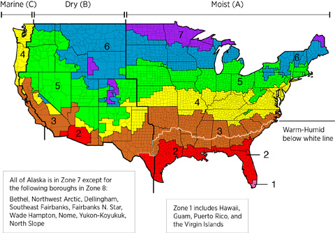
Region
Steam heating systems are predominantly located in the Northeast and Midwest regions of the United States. While balancing the distribution system can improve comfort and reduce energy in all steam-heated buildings, the potential energy savings will depend on how much energy the building uses for heating. All else being equal, buildings in colder climates (i.e., Zone 5 through 8) will see greater savings from the same scope of work. Local fuel prices and installation costs, along with weather severity, will inform energy-based simple payback estimates. However, the improved comfort and associated quality-of-life benefits can be achieved in any area.
The map in Figure 1 shows the climate zones for states that have adopted energy codes equivalent to the International Energy Conservation Code (IECC) 2009, 12, 15, and 18. The map in Figure 2 shows the climate zones for states that have adopted energy codes equivalent to the IECC 2021. Climate zone-specific requirements specified in the IECC are shown in the Compliance Tab of this guide.

Compliance
More Info
References and Resources
*For non-dated media, such as websites, the date listed is the date accessed.
Contributors to this Guide
The following authors and organizations contributed to the content in this Guide.
Sales
Direct/Power Vent Boiler
Technical Description
Safe-exhaust boilers are gas-fired units that completely isolate the supply of combustion air and combustion gas exhaust from indoors. As a result, combustion gases cannot spill into the home. In contrast, less-efficient gravity-exhaust natural gas- or propane-fired boilers draw combustion air from the room in which they are located and rely on an open flue to expel combustion exhaust up and out of the home. However, bath fans, kitchen hoods, and clothes dryers can potentially overcome the upward flow of exhaust in these non-sealed systems and draw combustion gases into the home.
Questions? Comments? Contact our webmaster.