
Rigid Foam Insulation Installed over Existing Foundation Slabs

    Scope
    Scope Images
    Image
    Retrofit of an existing basement slab by adding dimple plastic mat, rigid foam insulation, and a floating subfloor
    Scope

    Insulate an existing slab floor by adding rigid foam insulation over the slab then installing a floating subfloor as follows:

    • Treat any significant or persistent site water management issues that are contributing to basement water management issues first.
    • Inspect the existing slab for cracks, holes, and penetrations.
    • Clean the slab prior to beginning any repairs or retrofit work.
    • Seal the cracks, holes, and penetrations.
    • Install negative side vapor barrier.
    • Install rigid foam insulation.
    • Install sleepers if needed.
    • Install a floating subfloor.

    For more information, see the U.S. Department of Energy’s Standard Work Specifications regarding slab foundations.

    See the Compliance Tab for related codes and standards requirements, and criteria to meet national programs such as DOE’s Zero Energy Ready Home programENERGY STAR Single-Family New Homes, and Indoor airPLUS.

    Description
    Description

    If the existing basement slab is uninsulated, there are two options for adding insulation. One option is to remove the existing slab, excavate below, install insulation, then pour a new slab along with taking other appropriate moisture protection steps. This option is rarely considered feasible due to cost and other considerations. The other option is to install rigid foam insulation and water control measures on top of the existing slab. A floating subfloor is then installed either directly over the rigid foam insulation (Figures 1 and 2) or over furring strips (Figure 3).

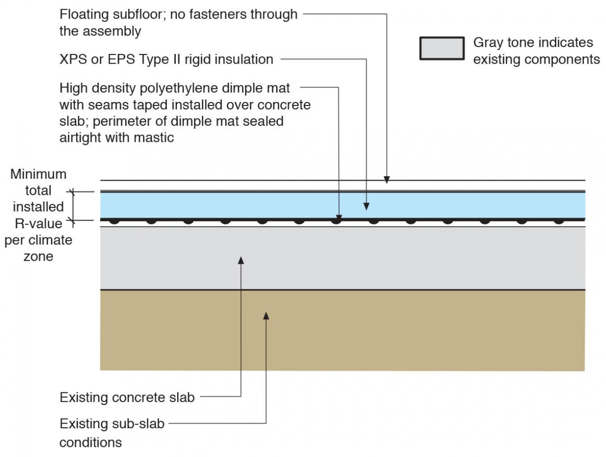
    When the existing slab is covered with rigid foam insulation, steps must be taken to manage moisture. One option includes providing a water drainage space underneath the insulation to allow water to be drained over the existing slab to a sump or other drainage system. This drainage space is completely isolated from the home by vapor-impermeable and air-impermeable materials. Figure 1 shows rigid insulation installed over an existing slab using polyethylene dimple mat as the drainage layer between the insulation and the existing slab. The other option (Figures 2 and 3) requires installation of a perimeter drain system tied into a sump or other drainage system. For more on sump pump installation, see the guide Drain or Sump Pump Installed in Basements or Crawlspaces.

    When performing basement retrofits, consider testing for radon. If radon levels warrant installation of a passive or active radon mitigation system it can be installed before insulation, vapor and water barrier layers are installed over the slab. See the guide Vertical Radon Ventilation Pipe for more information on radon testing and mitigation.

    Head height in the basement should be verified prior to beginning retrofit work in order to comply with the current adopted building code, as this retrofit measure will raise the floor height. Where it is not possible to add insulation over the existing basement slab due to insufficient head height in the basement, at a minimum, the slab should be patched and sealed to the foundation wall for soil gas control and epoxy paint should be applied to the surface for moisture transfer control. For more information on this approach see Water Management of Existing Basement Floor.

    Insulation with Floating Floor over Existing Slab with Drainage Layer between Insulation and Existing Slab

    A drainage mesh or dimple plastic mat is installed over the existing slab then covered with rigid foam and a floating subfloor (see Figure 1). The above-slab drainage layer must be connected to an interior sump pit. The interior sump pit must have an air tight and gasketed cover that is designed to provide the dual function of keeping soil gasses out and preventing ground water from entering the basement. (See the guide Sump Pump Cover Gasket.)

    Through-assembly fasteners should not be used because these would puncture the air and vapor control layers and could potentially admit soil gas that is collected in the air space below (in the drainage mesh or dimple mat).

    The existing basement slab is retrofitted by installing a dimple plastic drainage mat, rigid foam insulation, and a floating subfloor.
    Figure 1. The existing basement slab is retrofitted by installing a dimple plastic drainage mat, rigid foam insulation, and a floating subfloor.


    How to Install a Drainage Layer and Insulation with Floating Floor over an Existing Slab

    1. If significant or persistent water issues exist in the basement, treat those issues prior to sealing the slab.
    2. Consider testing radon levels in the basement and home prior to the sealing project. If a radon stack is needed, install it before urethane sealant and epoxy paint are applied.
    3. Inspect the existing slab for cracks, holes, and penetrations. Locate the areas that need to be addressed.
    4. Remove any debris or dust particles from the slab prior to applying urethane sealant to ensure proper adherence of the sealant.
    5. Apply a generous and continuous bead of urethane sealant to any cracks, holes, around any penetrations, and at wall-to-slab joints to prevent pest and soil gas (including radon) entry.
    6. Install a 6-mil polyethylene vapor barrier with seams taped or a high-density polyethylene dimple mat with seams taped (see Figure 1).
    7. Install rigid foam insulation (XPS or EPS Type II) with seams taped.
    8. Install a floating subfloor. Do not fasten the subfloor through the floor assembly.

    Insulation with Floating Floor Directly Over Existing Slab

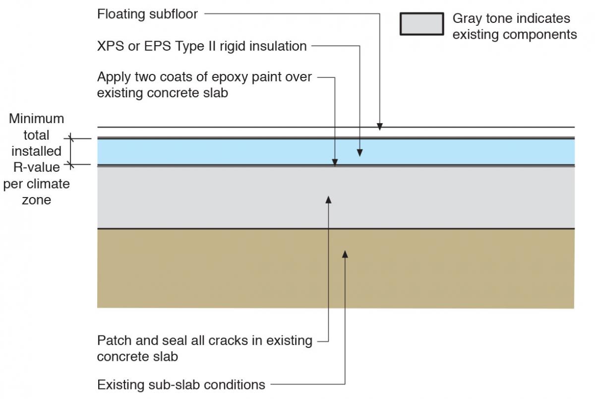
    Instead of drainage mat, the existing slab can be coated with two coats of epoxy paint, then rigid foam can be installed directly over the epoxy layer (see Figure 2). Use of this slab assembly requires a sub-slab drainage system such as an interior perimeter drain.

    The existing slab is retrofitted by coating with epoxy paint, then installing rigid foam insulation and a floating subfloor.
    Figure 2. The existing slab is retrofitted by coating with epoxy paint, then installing rigid foam insulation and a floating subfloor.


    How to Install Insulation with Floating Floor Directly over an Existing Slab

    1. If significant or persistent water issues exist in the basement, treat those issues prior to sealing the slab.
    2. Consider testing radon levels in the basement and home prior to the sealing project. If a radon stack is needed, install it before urethane sealant and epoxy paint are applied.
    3. Inspect the existing slab for cracks, holes, and penetrations. Locate the areas that need to be addressed.
    4. Remove any debris or dust particles from the slab prior to applying urethane sealant to ensure proper adherence of the sealant.
    5. Apply a generous and continuous bead of urethane sealant to any cracks, holes, around any penetrations, and at wall-to-slab joints to prevent pest and soil gas entry
    6. Apply two coats of epoxy paint over the existing slab. The area should be clear of dust and debris.
    7. Install rigid foam insulation (XPS or EPS Type II) with seams taped (see Figure 2).
    8. Install a floating subfloor. Do not fasten the subfloor through the floor assembly.

    Insulation with Sleepers and Floating Floor over Existing Slab with Drainage Layer between Insulation and Existing Slab

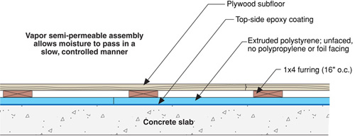
    A third option is to install unfaced rigid foam over an existing slab that has been coated with epoxy paint, then to install 1x4 sleepers for the plywood subfloor to sit on (see Figure 3). Use of this slab assembly requires a sub-slab drainage system such as an interior perimeter drain.

    The existing slab is retrofitted with epoxy paint, sleepers, and subfloor.
    Figure 3. The existing slab is retrofitted with epoxy paint, sleepers, and subfloor.


    How to Install Insulation with Sleepers and Floating Floor Directly Over an Existing Slab

    1. If significant or persistent water issues exist in the basement, treat those issues prior to sealing the slab.
    2. Consider testing radon levels in the basement and home prior to the sealing project. If a radon stack is needed, install it before urethane sealant and epoxy paint are applied.
    3. Inspect the existing slab for cracks, holes, and penetrations. Locate the areas that need to be addressed.
    4. Remove any debris or dust particles from the slab prior to applying urethane sealant to ensure proper adherence of the sealant.
    5. Apply a generous and continuous bead of urethane sealant to any cracks, holes, around any penetrations, and at wall-to-slab joints to prevent pest and soil gas entry.
    6. Apply two coats of epoxy paint over the existing slab. The area should be clear of dust and debris.
    7. Install rigid foam insulation (XPS or EPS Type II) with the seams taped (see Figure 3).
    8. Install 1x4 furring strips at 16 inches o.c. and attach them to the concrete slab through the rigid foam insulation.
    9. Install the plywood subfloor. Fasten the subfloor to the furring strips.
    Success
    Ensuring Success

    Apply urethane sealant and epoxy paint to a clean, dust-free surface.

    Visually verify the quality of the sealant application and paint application for continuous adhesion and coverage before proceeding to the next steps.

    Seal any penetrations in the slab, such as around sump pumps and plumbing and vent pipes.

    Climate
    Climate

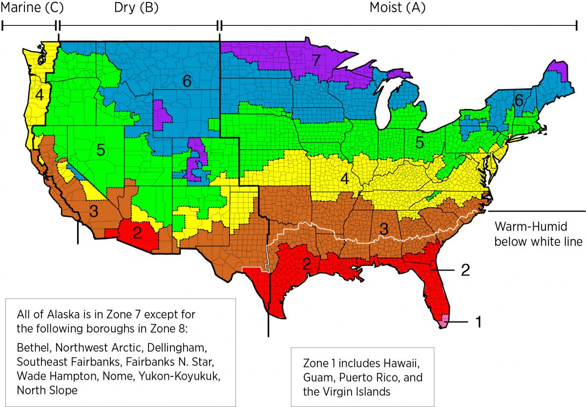
    The slab assembly should be designed for a specific hygrothermal region, rain exposure zone, and interior climate. 

    The map in Figure 1 shows the climate zones for states that have adopted energy codes equivalent to the International Energy Conservation Code (IECC) 2009, 12, 15, and 18. The map in Figure 2 shows the climate zones for states that have adopted energy codes equivalent to the IECC 2021. Climate zone-specific requirements specified in the IECC are shown in the Compliance Tab of this guide. 

    Climate Zone Map from IECC 2009, 12, 15, and 18.
    Figure 1. Climate Zone Map from IECC 2009, 12, 15, and 18. (Source: 2012 IECC)


    Climate Zone Map from IECC 2021.
    Figure 2. Climate Zone Map from IECC 2021. (Source: 2021 IECC)


    The insulation levels should be based on the minimum requirements for vapor control in the current adopted building code and the minimum requirements for thermal control in the current energy code. Additional insulation can be added above these minimums to create high R-value floor assemblies. The table below provides the minimum thermal resistance (R-value) requirements for slab floors specified in the 2009 IECC (ICC 2009b) and the 2012 IECC (ICC 2012b), based on climate zone.

    Minimum R-Value Requirements for Slab Insulation in the 2009 and 2012 IECC.

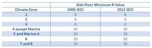
    Table 1. Minimum R-Value Requirements for Slab Insulation. (Source: 2009 IECC and 2012 IECC)


    Training
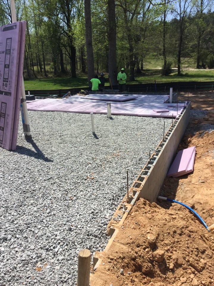
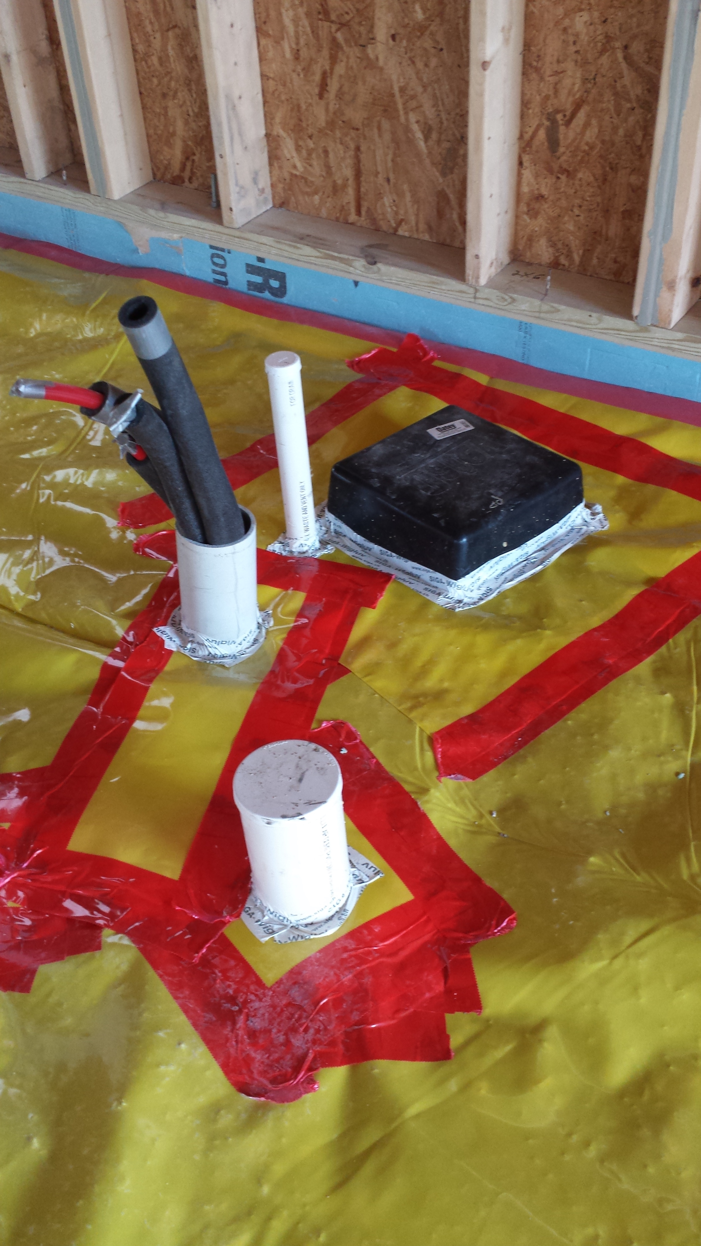
    Right and Wrong Images
    Image
    Right – The raised slab foundation has a 3-ft stem wall of filled concrete block, then is back-filled with compacted dirt and crushed rock, then insulated with 1” rigid foam covered with taped vapor barrier, under a floor slab.
    Right – The raised slab foundation has a 3-ft stem wall of filled concrete block, then is back-filled with compacted dirt and crushed rock, then insulated with 1” rigid foam covered with taped vapor barrier, under a floor slab.
    Image
    Right – All seams in the sub-slab vapor retarder were sealed with tape.
    Right – All seams in the sub-slab vapor retarder were sealed with tape.
    Image
    Right – The vapor barrier is thoroughly sealed with tape at all seams.
    Right – The vapor barrier is thoroughly sealed with tape at all seams.
    Compliance

    Compliance

    The Compliance tab contains both program and code information. Code language is excerpted and summarized below. For exact code language, refer to the applicable code, which may require purchase from the publisher. While we continually update our database, links may have changed since posting. Please contact our webmaster if you find broken links.


    ENERGY STAR Single-Family New Homes, Version 3/3.1 (Rev. 11)

    ENERGY STAR Single-Family New Homes requires that ceiling, wall, floor, and slab insulation levels meet or exceed those specified in the 2009 International Energy Conservation Code (IECC) with some alternatives and exceptions, and achieve Grade 1 installation per RESNET Standards (see 2009 and 2012 IECC Code Level Insulation – ENERGY STAR Requirements and Insulation Installation (RESNET Grade 1). If the state or local residential building energy code requires higher insulation levels than those specified in the 2009 IECC, you must meet or exceed the locally mandated requirements. Some states have adopted the 2012 or 2015 IECC. Visit the U.S. DOE Building Energy Codes Program to see what code has been adopted in each state.

    National Rater Design Review Checklist

    3. High-Performance Insulation.
    3.1 Specified ceiling, wall, floor, and slab insulation levels comply with one of the following options:
    3.1.1 Meets or exceeds 2009 IECC levels5, 6, 7 OR;
    3.1.2 Achieves ≤ 133% of the total UA resulting from the U-factors in 2009 IECC Table 402.1.3, per guidance in Footnote 5d, AND specified home infiltration does not exceed the following:6, 7

    • 3 ACH50 in CZs 1, 2
    • 2.5 ACH50 in CZs 3, 4
    • 2 ACH50 in CZs 5, 6, 7
    • 1.5 ACH50 in CZ 8

    Footnote 5) Specified levels shall meet or exceed the component insulation levels in 2009 IECC Table 402.1.1. The following exceptions apply:
    a. Steel-frame ceilings, walls, and floors shall meet the insulation levels of 2009 IECC Table 402.2.5. In CZ 1 and 2, the continuous insulation requirements in this table shall be permitted to be reduced to R-3 for steel-frame wall assemblies with studs spaced at 24 in. on center. This exception shall not apply if the alternative calculations in d) are used;
    b. For ceilings with attic spaces, R-30 shall satisfy the requirement for R-38 and R-38 shall satisfy the requirement for R-49 wherever the full height of uncompressed insulation at the lower R-value extends over the wall top plate at the eaves. This exemption shall not apply if the alternative calculations in d) are used;
    c. For ceilings without attic spaces, R-30 shall satisfy the requirement for any required value above R-30 if the design of the roof / ceiling assembly does not provide sufficient space for the required insulation value. This exemption shall be limited to 500 sq. ft. or 20% of the total insulated ceiling area, whichever is less. This exemption shall not apply if the alternative calculations in d) are used;
    d. An alternative equivalent U-factor or total UA calculation may also be used to demonstrate compliance, as follows: An assembly with a U-factor equal or less than specified in 2009 IECC Table 402.1.3 complies. A total building thermal envelope UA that is less than or equal to the total UA resulting from the U-factors in Table 402.1.3 also complies. The performance of all components (i.e., ceilings, walls, floors, slabs, and fenestration) can be traded off using the UA approach. Note that Items 3.1 through 3.3 of the National Rater Field Checklist shall be met regardless of the UA tradeoffs calculated. The UA calculation shall be done using a method consistent with the ASHRAE Handbook of Fundamentals and shall include the thermal bridging effects of framing materials. The calculation for a steel-frame envelope assembly shall use the ASHRAE zone method or a method providing equivalent results, and not a series-parallel path calculation method.

    Footnote 6) Consistent with the 2009 IECC, slab edge insulation is only required for slab-on-grade floors with a floor surface less than 12 inches below grade. Slab insulation shall extend to the top of the slab to provide a complete thermal break. If the top edge of the insulation is installed between the exterior wall and the edge of the interior slab, it shall be permitted to be cut at a 45-degree angle away from the exterior wall. Alternatively, the thermal break is permitted to be created using ≥ R-3 rigid insulation on top of an existing slab (e.g., in a home undergoing a gut rehabilitation). In such cases, up to 10% of the slab surface is permitted to not be insulated (e.g., for sleepers, for sill plates). Insulation installed on top of slab shall be covered by a durable floor surface (e.g., hardwood, tile, carpet).

    Footnote 7) Where an insulated wall separates a garage, patio, porch, or other unconditioned space from the conditioned space of the house, slab insulation shall also be installed at this interface to provide a thermal break between the conditioned and unconditioned slab. Where specific details cannot meet this requirement, partners shall provide the detail to EPA to request an exemption prior to the home’s certification. EPA will compile exempted details and work with industry to develop feasible details for use in future revisions to the program. A list of currently exempted details is available at: energystar.gov/slabedge.

    National Rater Field Checklist

    Thermal Enclosure System
    1. High-Performance Fenestration & Insulation.
    1.3 All insulation achieves Grade I install. per ANSI / RESNET / ICC Std. 301. Alternatives in Footnote 5.5, 6

    2. Fully-Aligned Air Barriers 7 - At each insulated location below, a complete air barrier is provided that is fully aligned as follows:
    Ceilings: At interior or exterior horizontal surface of ceiling insulation in Climate Zones 1-3; at interior horizontal surface of ceiling insulation in Climate Zones 4-8. Also, at exterior vertical surface of ceiling insulation in all climate zones (e.g., using a wind baffle that extends to the full height of the insulation in every bay or a tabbed baffle in each bay with a soffit vent that prevents wind washing in adjacent bays). 8
    Walls: At exterior vertical surface of wall insulation in all climate zones; also at interior vertical surface of wall insulation in Climate Zones 4-8.9
    Floors: At exterior vertical surface of floor insulation in all climate zones and, if over unconditioned space, also at interior horizontal surface including supports to ensure alignment. Alternatives in Footnotes 12 & 13.11, 12, 13

    Footnote 5) Two alternatives are provided: a) Grade II cavity insulation is permitted to be used for assemblies that contain a layer of continuous, air impermeable insulation ≥ R-3 in Climate Zones 1 to 4, ≥ R-5 in Climate Zones 5 to 8; b) Grade II batts are permitted to be used in floors if they fill the full width and depth of the floor cavity, even when compression occurs due to excess insulation, as long as the R-value of the batts has been appropriately assessed based on manufacturer guidance and the only defect preventing the insulation from achieving Grade I is the compression caused by the excess insulation.

    Footnote 6) Ensure compliance with this requirement using ANSI / RESNET / ICC Std. 301 including all Addenda and Normative Appendices, with new versions and Addenda implemented according to the schedule defined by the HCO that the home is being certified under, with approved exceptions listed at www.energystar.gov/ERIExceptions.

    Footnote 7) For purposes of this Checklist, an air barrier is defined as any durable solid material that blocks air flow between conditioned space and unconditioned space, including necessary sealing to block excessive air flow at edges and seams and adequate support to resist positive and negative pressures without displacement or damage. EPA recommends, but does not require, rigid air barriers. Open-cell or closed-cell foam shall have a finished thickness ≥ 5.5 in. or 1.5 in., respectively, to qualify as an air barrier unless the manufacturer indicates otherwise. If flexible air barriers such as house wrap are used, they shall be fully sealed at all seams and edges and supported using fasteners with caps or heads ≥ 1 in. diameter unless otherwise indicated by the manufacturer. Flexible air barriers shall not be made of kraft paper, paper-based products, or other materials that are easily torn. If polyethylene is used, its thickness shall be ≥ 6 mil.

    Footnote 8) All insulated ceiling surfaces, regardless of slope (e.g., cathedral ceilings, tray ceilings, conditioned attic roof decks, flat ceilings, sloped ceilings), must meet the requirements for ceilings.

    Footnote 9) All insulated vertical surfaces are considered walls (e.g., above and below grade exterior walls, knee walls) and must meet the air barrier requirements for walls. The following exceptions apply: air barriers recommended, but not required, in adiabatic walls in multifamily dwellings; and, in Climate Zones 4 through 8, an air barrier at the interior vertical surface of insulation is recommended but not required in basement walls or crawlspace walls. For the purpose of these exceptions, a basement or crawlspace is a space for which ≥ 40% of the total gross wall area is below-grade.

    Footnote 11) EPA highly recommends, but does not require, an air barrier at the interior vertical surface of floor insulation in Climate Zones 4-8.

    Footnote 12) Examples of supports necessary for permanent contact include staves for batt insulation or netting for blown-in insulation. Alternatively, supports are not required if batts fill the full depth of the floor cavity, even when compression occurs due to excess insulation, as long as the R-value of the batts has been appropriately assessed based on manufacturer guidance and the only defect preventing the insulation from achieving the required installation grade is the compression caused by the excess insulation.

    Footnote 13) Alternatively, an air barrier is permitted to be installed at the exterior horizontal surface of the floor insulation if the insulation is installed in contact with this air barrier, the exterior vertical surfaces of the floor cavity are also insulated, and air barriers are included at the exterior vertical surfaces of this insulation.

    National Water Management System Builder Requirements

    1. Water-Managed Site and Foundation. 
    1.7 Sump pit cover mechanically attached with full gasket seal or equivalent.

    Please see the ENERGY STAR Single-Family New Homes Implementation Timeline for the program version and revision currently applicable in your state.


    DOE Zero Energy Ready Home (Revision 07)

    The DOE Zero Energy Ready Home Program is a voluntary high-performance home labeling program for new homes operated by the U.S. Department of Energy. Builders and remodelers who are performing retrofits on existing homes are welcome to seek certification for those homes through this voluntary program.

    Exhibit 1 Mandatory Requirements.
    Exhibit 1, Item 1) Certified under the ENERGY STAR Qualified Homes Program or the ENERGY STAR Multifamily New Construction Program.
    Exhibit 2, Item 2) Ceiling, wall, floor, and slab insulation shall meet or exceed 2015 IECC levels and achieve Grade 1 installation, per RESNET standards.


    2009-2021 IECC and IRC Insulation Requirements Table

    The minimum insulation requirements for ceilings, walls, floors, and foundations in new homes, as listed in the 2009, 2012, 2015, 2018, and 2021 IECC and IRC, can be found in this table


    200920122015, 2018, and 2021 International Energy Conservation Code (IECC)

    Section R402.4 Air leakage (Mandatory).

    Section R402.4.1 Building Thermal Envelope.

    Table R402.1.2 (402 .1.1 in 2009 and 2012 IECC) Insulation and fenestration requirements by component.

    Table R402.4.1.1 (R402.4.2 in 2009 IECC) Air Barrier and Insulation Installation and Component Criteria

    Retrofit:  2009, 2012, 2015, 2018,  and 2021 IECC

    Section R101.4.3 (in 2009 and 2012). Additions, alterations, renovations, or repairs shall conform to the provisions of this code, without requiring the unaltered portions of the existing building to comply with this code. (See code for additional requirements and exceptions.)

    Chapter 5 (in 2015, 2018, 2021). The provisions of this chapter shall control the alteration, repair, addition, and change of occupancy of existing buildings and structures.


    2009, 2012, 2015, 2018,  and 2021 International Residential Code (IRC)

    Section R317 Protection of wood and wood based products against decay.

    Section R317.1 Location required.

    Section R318 Protection against subterranean termites.

    Section R318.4 Foam plastic protection.

    Section N1102 Building thermal envelope.

    Table N1102.1.2 (N1102.1.1 in 2009 and 2012 IRC) Insulation and fenestration requirements by component.

    Section N1102.4 (R402.4) Air leakage (Mandatory).

    Section N1102.4.1 (N1102.4.2 in 2009 IRC) Building thermal envelope.

    Retrofit:  2009, 2012, 2015, 2018,  and 2021 IRC

    Section R102.7.1 Additions, alterations, or repairs. Additions, alterations, renovations, or repairs shall conform to the provisions of this code, without requiring the unaltered portions of the existing building to comply with the requirements of this code, unless otherwise stated. (See code for additional requirements and exceptions.)

    Appendix J regulates the repair, renovation, alteration, and reconstruction of existing buildings and is intended to encourage their continued safe use.

    More

    More Info.

    Access to some references may require purchase from the publisher. While we continually update our database, links may have changed since posting. Please contact our webmaster if you find broken links.

    References and Resources*
    Author(s)
    Neuhauser Ken,
    Gates Cathy,
    Pettit Betsy
    Organization(s)
    Building Science Corporation,
    BSC
    Publication Date
    Description
    Guidebook providing useful examples of high performance retrofit techniques for the building enclosure of wood frame residential construction in a cold and somewhat wet climate.
    Author(s)
    Lstiburek Joseph W
    Organization(s)
    Building Science Corporation,
    BSC
    Publication Date
    Description
    Information guide describing issues with concrete floors, in multiple climate zones.
    *For non-dated media, such as websites, the date listed is the date accessed.
    Contributors to this Guide

    The following authors and organizations contributed to the content in this Guide.

    Building Science Corporation, lead for the Building Science Consortium (BSC), a DOE Building America Research Team

    Sales
    Building Science Measures
    Building Science-to-Sales Translator

    High-R Foundation Insulation = High-Efficiency or Ultra-Efficient Foundation Insulation

    Image(s)
    Technical Description

    There are two levels of foundation insulation: high-efficiency insulation, which meets the 2015 International Energy Conservation Code, and ultra-efficient insulation, which is 25% more efficient than this national code. Using high-efficiency and ultra-efficient insulation, along with professional installation (e.g., no gaps, voids, compression, or misalignment with air barriers; complete air barriers; and minimal thermal bridging) creates conditioned spaces that require very little heating and cooling, along with, even comfort and quiet throughout the house.

    High-Efficiency or Ultra-Efficient Foundation Insulation
    Sales Message

    High-efficiency foundation insulation helps provide added thermal protection. What this means to you is less wasted energy along with enhanced comfort and quiet. Knowing there is one opportunity to optimize performance during construction, wouldn’t you agree it’s a great opportunity to meet or exceed future codes?

    Last Updated

    Did you find this information helpful?

    If you have questions and/or would like a reply to this feedback, please include your e-mail address in the message.
    This question is for testing whether or not you are a human visitor and to prevent automated spam submissions.