

Scope
In high-wind zones, construct low-slope (“flat”) insulated roof assemblies that resist the wind pressures that can pull off membrane roof coverings during high-wind events such as hurricanes.
- Install the roof decking in accordance with IBHS Fortified Home sheathing nailing pattern recommendations.
- Seal the roof deck sheathing by covering the entire plywood or OSB sheathing with a self-adhering “peel and stick” membrane or by sealing the sheathing seams with compatible tape.
- Install one or more layers of rigid foam insulation with seams staggered and taped.
- Install an exterior sheathing layer.
- Select a roof covering that is appropriate for the maximum design wind uplift pressures expected for the site, following the recommendations of the IBHS Fortified Home program. A fully adhered roof membrane is recommended.
See the Compliance Tab for links to related codes and standards and voluntary federal energy-efficiency program requirements.
Description
In high-wind zones, low-slope ("flat") roof assemblies (slope less than 2:12) with a waterproofing roof membrane cladding need to be able to resist the wind pressures that can act on them during high-wind events such as hurricanes.
Low-slope roof coverings include built-up bitumen roof systems, modified bitumen roof systems, and single-ply roofing membranes, including thermoplastic membranes such as TPO (thermoplastic olefin), PVC (polyvinyl chloride), and KEE (ketone ethylene ester), and thermoset membranes such as EPDM (ethylene propylene diene monomer). This guide discusses single-ply roofing membranes, the most commonly used flat-roof cladding in residential construction today. The IBHS Fortified Home program recommends that the low-slope roofing system and installation method selected is adequate for the highest design pressures expected on the roof at the site. Maximum design wind uplift pressures for low-slope roofs are listed in Table 2-5 of ASCE 7, Minimum Design Loads for Buildings and Other Structures. The International Residential Code 2012, 2015, and 2018, reference the ASCE-7-10. IBHS recommends that builders follow the values in ASCE 7-16, which are based on more recent research on design loads for low-slope roofs. To certify a home to IBHS Fortified Home, IBHS requires that the roofing manufacturer's tested uplift design pressures must have a factor of safety of 2.0. IBHS notes that the following reports can be used to validate compliance with the project site-specific design pressure requirements because they already have the 2.0 factor of safety applied: an ICC Evaluation Service Report, the Florida Product Approval list, or the Miami-Dade Notice of Acceptance (NOA). For more information, see the IBHS Fortified Home Hurricane Standard,
Single-ply roof membranes can be either mechanically attached or fully adhered to the low-slope roof's rigid insulation or cover board. This guide describes problems that have been noted in the field with mechanically attached single-ply membranes and recommends installation methods to increase the roof claddings' resistance to wind uplift pressures.
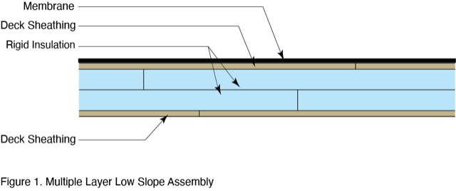
Low-slope roof assemblies that are insulated above the roof deck are typically constructed from multiple layers (Figure 1), including plywood or OSB deck sheathing, one or more layers of rigid isocyanurate or extruded polystyrene (XPS), and an upper covering board of plywood or OSB. It is common for the single-ply roofing membrane installed over the coverboard to be mechanically attached rather than fully adhered.
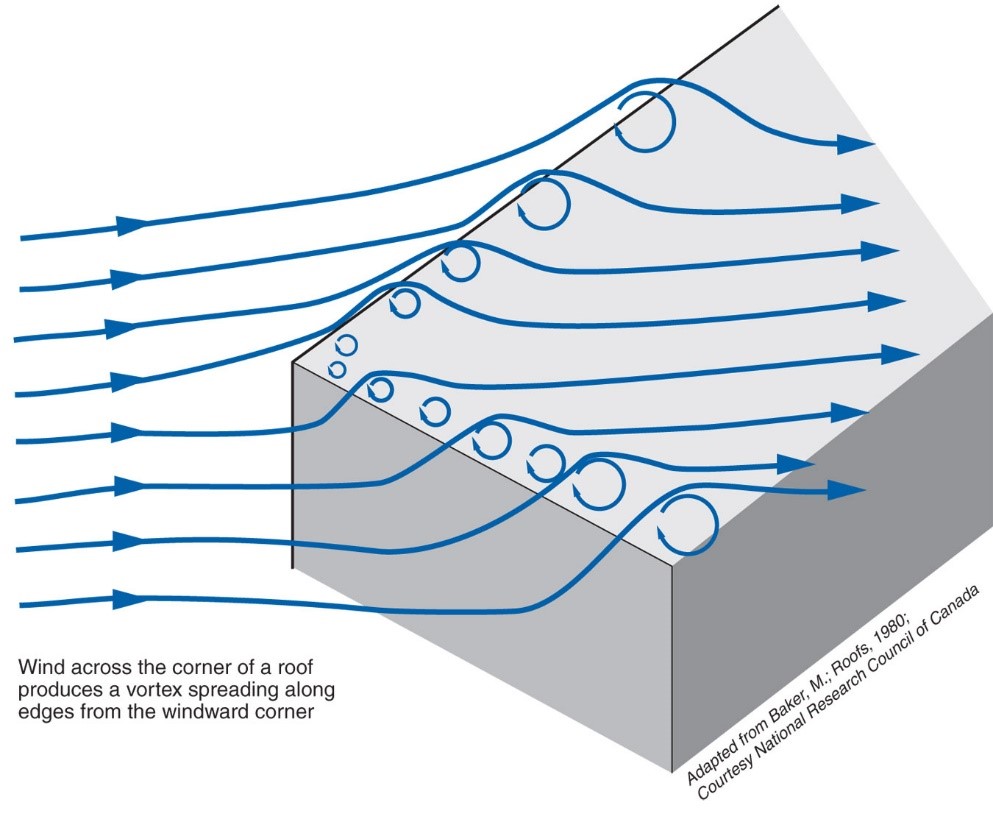
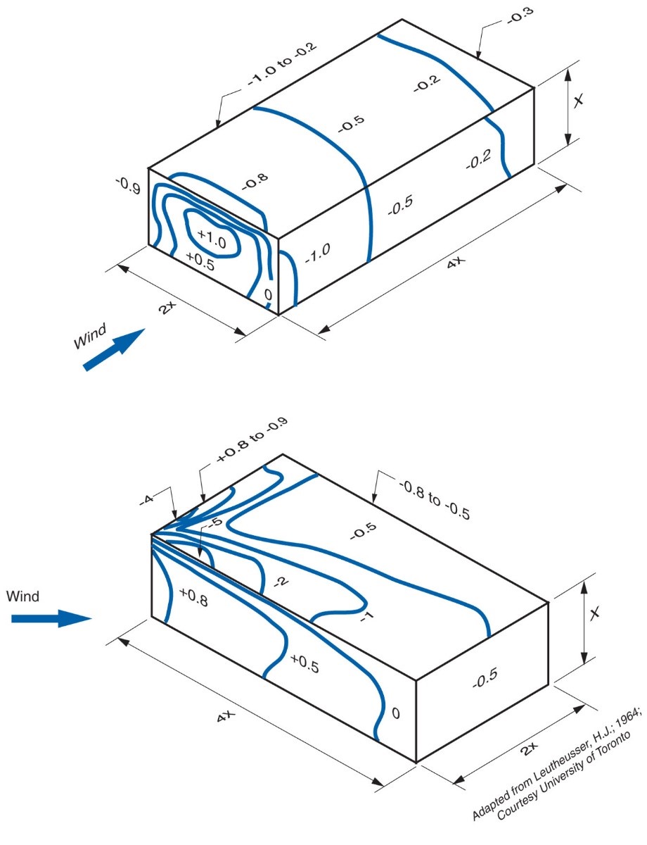
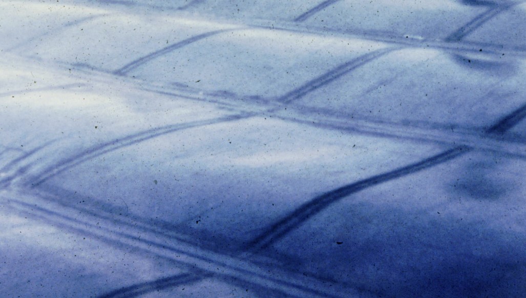
During high-wind events, highly localized areas of negative pressure (“suction”) occur above the roof membrane (Figure 2 and Figure 3). Interior spaces can simultaneously experience high positive pressures, especially if a window or door is “blown-in” or fails. This type of high positive interior pressure increases the risk of roof failure, especially in a multi-layer roof assembly where elements (or layers) are not sealed and where roof membranes are mechanically attached and not fully adhered. When air from within the building is allowed to leak into the roof assembly, the membrane can “flutter” and ultimately fail (Figure 4 and Figure 5). This flutter is caused by a combination of the negative pressures above the roof membrane due to wind and the positive pressures beneath the membrane due to air leakage into the assembly.
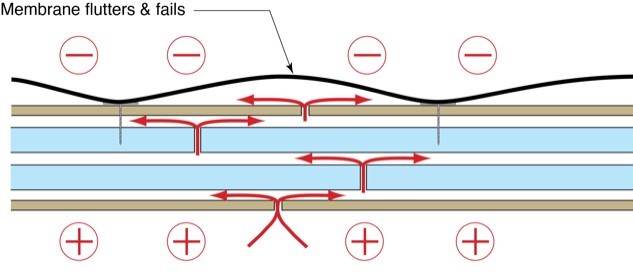
P(t) = P(m) + P(d) + P(i) + P(i) + P(d)
Where P(t) = total wind pressure
P(m) = membrane pressure
P(d) = deck pressure
P (i) = insulation pressure
P(d) = deck pressure
The most airtight (“tightest”) element experiences the most significant pressure. In most roof assemblies, the tightest element is the roof membrane itself, so it, therefore, often experiences the greatest wind load.
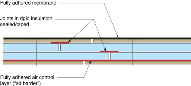
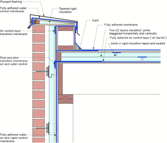
In high-wind zones, fully adhered membranes are recommended. Additionally, a fully adhered air control layer (“air barrier”) should be installed at the lower deck sheathing, and joints in the rigid insulation should be sealed or taped (Figure 6). This approach reduces the air leakage into the assembly and thus the air pressure difference across the upper membrane and thereby reduces the risk of membrane failure due to “blow off” and “fluttering.”

Fluttering, besides stressing the membrane, leads to the pumping transfer of airborne moisture from the interior into the roof assembly in cold and mixed climates. Historically, this has typically been a cold-climate phenomenon, but the problems are migrating south as membranes become white rather than black. Dark membranes get very hot – and the heat drives the moisture back down into the building. In warmer climate zones, mechanically attached dark membrane roofs avoided moisture issues because the moisture that was pumped up was driven back down by the huge temperature gradient. However, with energy conservation and light-colored membranes, many roofs no longer get hot enough to drive flutter-driven moisture back down into the building. Failures that were limited to cold climates now happen in mixed climates.
Air control layers (“air barriers”) control fluttering since any attempt by the membrane to lift off the insulation layers is resisted by suction – air from the interior is not able to enter the roof assembly due to the presence of the lower control layer (“air barrier”). The lack of an air control layer and a leaky deck will allow replacement air to enter the roof assembly from the interior, and the suction resistance is lost (Figure 4).
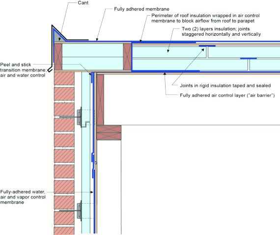
It is necessary to provide a connection between the lower air control layer (“air barrier”) of the roof assembly and the roof membrane with the wall system (Figure 7 and Figure 8). It is also necessary to provide connection and continuity of the water control layer of the roof assembly with the water control layer of the wall assembly.
Modified Approach
The fully adhered air control layer (“air barrier”) at the lower deck sheathing can be omitted if the lower roof deck sheathing joints are sealed with tape or membrane strips that are compatible with the plywood or OSB sheathing.
Structural Attachment
Fastener spacing and type for the lower deck sheathing should follow the minimum requirements specified by the Insurance Institute for Building and Home Safety (IBHS) Fortified Home Program. These are described in the IBHS Fortified Roof Standard Detail Set for Fortified Roof (2019).
For the upper deck sheathing, the fasteners should be epoxy-coated steel screws installed on 6-inch centers. Rigid insulation should be limited to a maximum thickness of 10 inches and installed using multiple 2-inch-thick sheets with joints offset horizontally and vertically.
Tapes and Membranes
Tapes and membrane selection for sealing the lower sheathing joints should follow the recommendations of the Insurance Institute for Business & Home Safety as described in their guide Choosing the Right Tape. Tapes for sealing the joints in rigid insulation should be acrylic-based, and selection should follow the recommendations of the Insurance Institute for Business & Home Safety in Choosing the Right Tape.
Ensuring Success
Provide a high degree of airtightness at the lower roof deck sheathing either by using a fully adhered membrane air control layer (“air barrier”) or by sealing the joints of the lower roof deck sheathing with tape or membrane strips. Tape should be applied with a roller to ensure consistent pressure.
Connections at roof perimeters are important as uplift forces are the greatest.
The IBHS Fortified Home program offers online training for roofers through its Fortified Wise University program.
Region
Select a roof covering that is appropriate for the maximum design wind uplift pressures expected for the site, following the recommendations of the IBHS Fortified Home program. A fully adhered roof membrane is recommended. The installation approach given on the Description tab works in all climates to reduce the risk of roof membrane blow-off or fluttering. In cold climates, this approach also addresses high interior moisture loads that can lead to condensation within the layers of the roof assembly. In cold climates, snow loads must be considered in the structural design. Hail damage is minimized in high-hail zones by the use of deck sheathing to support the roof membrane. See the Compliance tab for more information on the minimum levels of roof assembly thermal resistance required by code in each climate zone.
Training
Right and Wrong Images

Source

Source

Source
Videos


Compliance
Retrofit
An existing low-slope roof can be retrofitted to improve the water-resistance and wind resistance of the roof as described in the Description tab of this guide. The thermal performance of the roof can also be improved by adding insulation under the roof deck or by adding insulation above the roof deck as described in this guide and also in the guide Water Managed Roof – Re-roofing and Adding Insulation over a Flat Roof.
For more on roof/wall connections, see the U.S. Department of Energy’s Standard Work Specifications.
More Info
References and Resources
*For non-dated media, such as websites, the date listed is the date accessed.
Contributors to this Guide
The following authors and organizations contributed to the content in this Guide.
The following authors and organizations contributed to the content in this Guide:
Building Science Corporation.
Questions? Comments? Contact our webmaster.