

Scope
Upgrade a wall with a floor overhang (or cantilever) on an existing home by adding rigid insulating sheathing and or closed-cell spray foam insulation and air sealing as follows:
- Inspect the existing wall and overhang framing for any deficiencies and make any corrections if necessary. Develop specific detailing for insulating the overhang area.
- Provide four control layers that are continuous over the wall and overhang assemblies: water, air, vapor, and thermal.
- Install exterior wall insulation and interior framing cavity insulation to levels that meet or exceed the current adopted building and energy codes.
See the Compliance Tab for links to related codes and standards and voluntary federal energy-efficiency program requirements.
Description
When upgrading the wall insulation in an existing home (for example when replacing siding), carefully inspect at any locations in the home with overhanging (or cantilevered) floors. Cantilevered floors in existing homes are frequently found to be uninsulated and not air sealed, causing cold (or hot) areas in the spaces around these floors.
The underside of the overhanging floor is a part of the home’s thermal boundary; it is essentially a continuation of the wall above and below. All of the protective layers found in the wall should also be present on the underside of this overhanging floor. There should be an air barrier, a vapor control layer, a thermal control layer, and a water control layer. The air, vapor, and thermal layers must be continuous with those layers in the exterior wall above the overhang. The water control layer in the wall must terminate at the lower edge of the wall in a way that directs water away from the building. The overhang itself acts like a roof, protecting the vertical wall below it so the water control layer does not necessarily need to be continuous from the exterior wall above the overhang to the underside of the overhang. However, if the overhang is near ground level, the surface of the underside of the overhang should be resistant to rain water that may splash up from the ground in front of the overhang.
Maintaining continuity of the other building enclosure control functions can be challenging at overhanging floors. Below the overhang, the overhanging floor might connect to an exterior frame wall assembly or to a foundation wall. As with roof-wall transitions, effective continuity of the air control layer will rely on careful implementation and an understanding of the many connections that must be made airtight in order to connect the air control layer of the wall above the overhang to that of the overhang itself and to the wall or foundation beneath the overhang. For more information on air sealing and insulating these complex building components, see the guide Cantilevered Floor.
The underside of the overhanging floor might be covered with exterior wall cladding or might be left unfinished. If it is not covered with siding, some other solid material must be provided as means of critter protection.
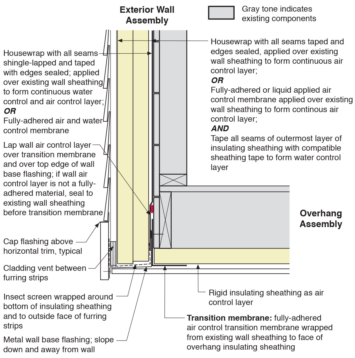
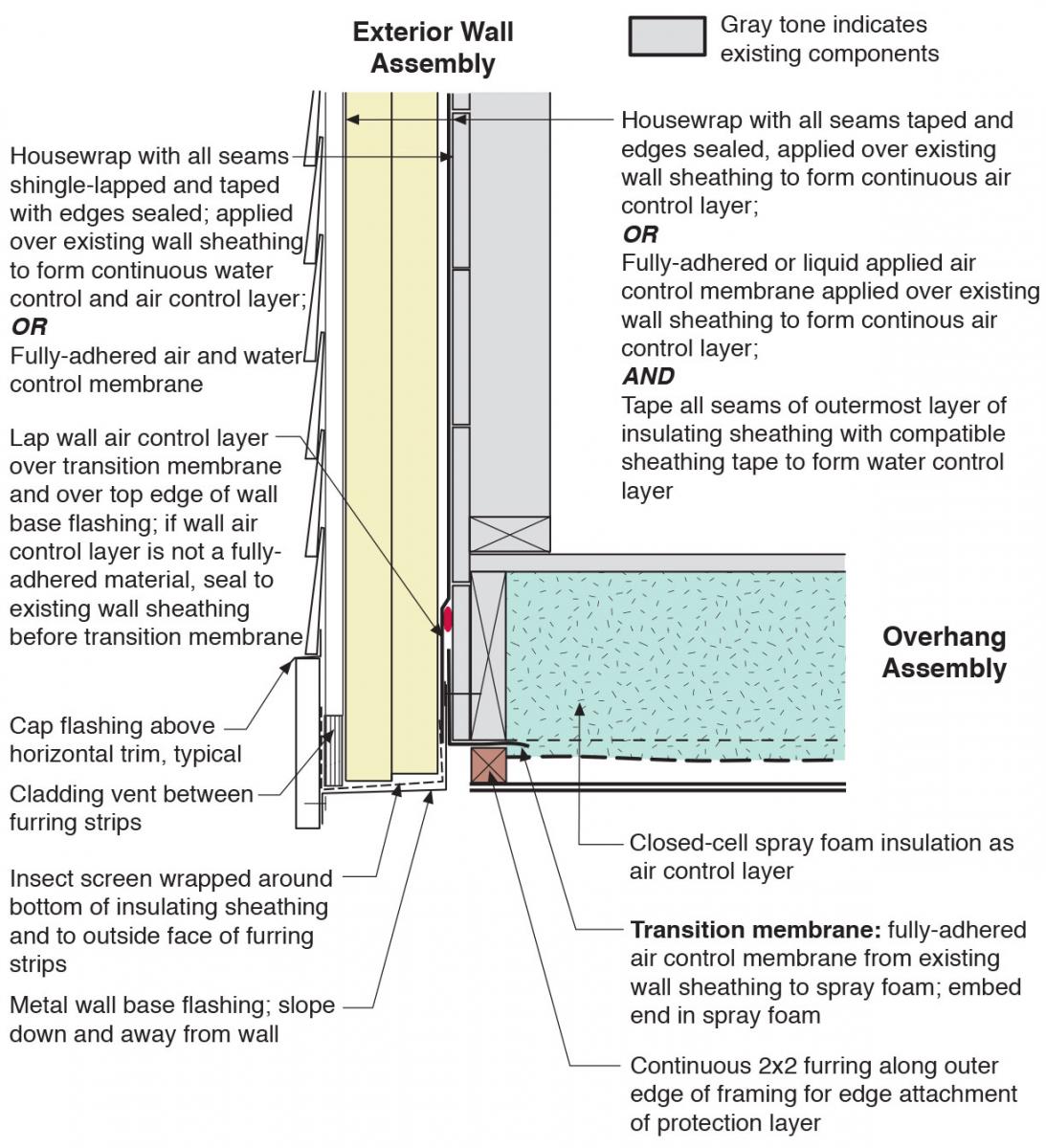
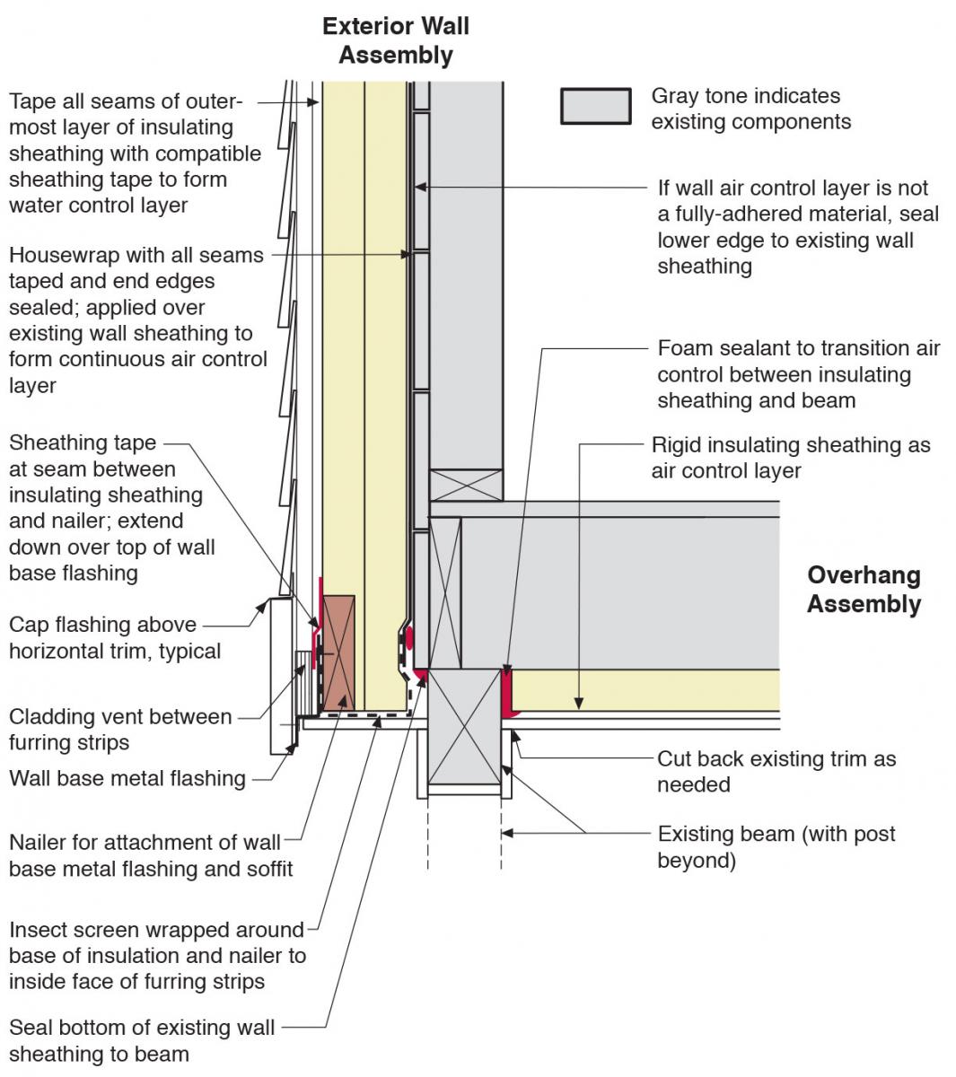
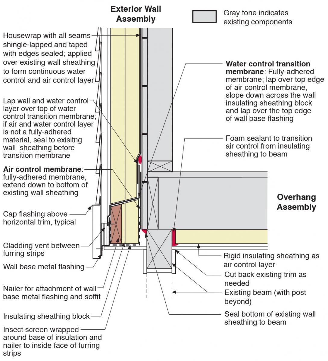
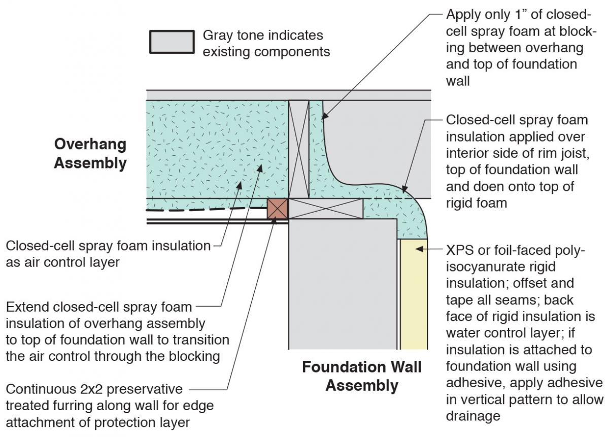
Figures 1 to 5 show overhang air sealing and insulating details that will be applicable to many but not all overhanging floor conditions. Figure 1 shows a wall-to-overhanging floor transition at the outside corner, that is insulated using rigid insulating sheathing. Figure 2 shows a wall-to-overhanging floor transition at the outside corner, where the overhanging floor is insulated using closed-cell spray foam insulation, which also acts as the air control layer. Figure 3 shows a wall-to-overhanging floor transition with a beam at the outside corner, insulated using rigid insulating sheathing and with the water control layer in front of the rigid insulating sheathing. Figure 4 is a variation of Figure 3 with the water control layer behind the insulating sheathing. Figure 5 shows a wall-to-overhanging floor transition at the inside corner insulated using rigid insulating sheathing. Figure 6 shows a foundation wall-to-overhanging floor transition at the inside corner, where the overhanging floor is insulated using closed-cell spray foam.
The details in Figures 1 to 5 show retrofit situations where exterior rigid insulating sheathing has been added to the exterior vertical walls. Most of the air sealing and insulation details shown would be applicable to overhang retrofits even if rigid foam insulation were not added to the exterior vertical walls.


How to Insulate a Floor Overhang with Rigid Foam Sheathing
- Inspect the structural integrity of the wall and the overhang. Check the framing for any deficiencies, rot, insect damage, etc. Only proceed if any needed repairs are performed. Based on the findings, revise the wall and overhang assembly and review specific detailing as needed. Follow the minimum requirements of the current adopted building and energy codes.
- Perform any needed air sealing of the floor joist cavities. Block and air seal any floor joist bays that are open from the cantilevered floor to the building interior.
- Install rigid foam insulating sheathing at the underside of the overhang (See Figures 1, 3, 4 and 5). Alternately, the floor joist cavities can be filled with closed-cell spray foam.
- Install a transition membrane from the existing wall sheathing onto the face of the overhang insulating sheathing. Tape the top edge of the air control layer at the inside corner of the overhang (See Figure 5).
- Install the metal wall base flashing (See Figures 1 to 4). The flashing should slope down and away from the wall. Install the transition membrane from the face of the overhang insulating sheathing to the wall air control layer.
- Lap the air control layer at the existing wall sheathing over the transition membrane and over the top edge of the wall base flashing (Figures 1 and 2).
- Install insulating sheathing on the wall (Figures 1 to 5). Wrap insect screen around the bottom of the bottom layer of the insulating sheathing and to the face of the furring strips.
- Install a fully adhered water control membrane at the intersection of the overhang insulating sheathing and wall insulating sheathing (Figure 5).
- Attach the furring strips through the insulating sheathing to the structure of the house.
- Attach the cladding to the furring strips.
Ensuring Success
Inspect the existing wall and overhang framing for any deficiencies and make any corrections if necessary.
Ensure the thermal, air, vapor, and water control layers of the roof and wall assemblies are continuous.
Ensure proper lapping of building layers to shed water away from the wall and overhang assemblies.
Region
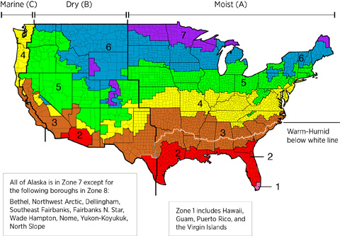
The building assemblies should be designed for a specific hygrothermal region, rain exposure zone, and interior climate.
The map in Figure 1 shows the climate zones for states that have adopted energy codes equivalent to the International Energy Conservation Code (IECC) 2009, 12, 15, and 18. The map in Figure 2 shows the climate zones for states that have adopted energy codes equivalent to the IECC 2021. Climate zone-specific requirements specified in the IECC are shown in the Compliance Tab of this guide.

The insulation levels should be based on the minimum requirements for vapor control in the current adopted building code and the minimum requirements for thermal control in the current energy code. Additional insulation can be added above these minimums to create high R-value wall and floor assemblies. The tables below provide the minimum thermal resistance (R-value) requirements for framed walls and floors specified in the 2009 IECC (ICC 2009b) and the 2012 IECC (ICC 2012b), based on climate zone.
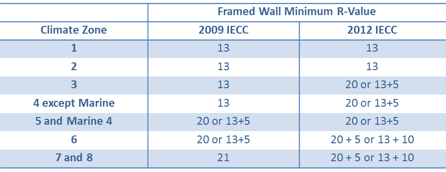
Table 1. Framed Wall R-Value Requirements in the 2009 and 2012 IECC. (Source: 2009 IECC and 2012 IECC)
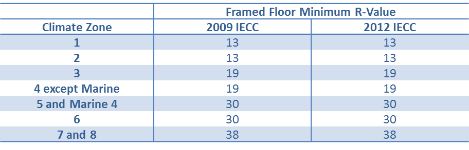
Table 2. Framed Floor R-Value Requirements in the 2009 and 2012 IECC. (Source: 2009 IECC and 2012 IECC)
Guidance for the ratios of permeable to impermeable insulation for vapor control can be found in Table 3. Table 3 presents information taken from Table R601.3.1 Class III Vapor Retarders of the 2009 IRC (ICC 2009a) and Table R702.7.1 Class III Vapor Retarders of the 2012 IRC (ICC 2009b). It shows minimum thermal resistance values to control condensation using exterior insulating sheathing for Climate Zones 5, 6, 7, 8, and Marine 4. The percentage of the total insulation that is exterior insulation (e.g., insulating sheathing/spray foam insulation) is also shown in the table. These percentages can be used to calculate R-value ratios for ccSPF vs. fibrous fill in “hybrid” double stud walls.
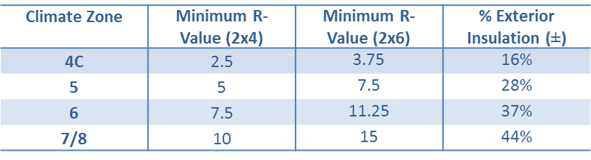
Table 3. R-Value Requirements for Vapor Control in the 2009 and 2012 IECC. (Source: 2009 IECC and 2012 IECC)
Compliance
More Info
References and Resources
*For non-dated media, such as websites, the date listed is the date accessed.
Contributors to this Guide
The following authors and organizations contributed to the content in this Guide.
Building Science Corporation, lead for the Building Science Consortium (BSC), a DOE Building America Research Team
Sales
High-R Floor Insulation = High-Efficiency or Ultra-Efficient Floor Insulation
Technical Description
There are two levels of floor insulation: high-efficiency insulation, which meets the 2015 International Energy Conservation Code, and ultra-efficient insulation, which is 25% more efficient than this national code. Using high-efficiency and ultra-efficient insulation along with professional installation (e.g., no gaps, voids, compression, or misalignment with air barriers; complete air barriers; and minimal thermal bridging) creates conditioned spaces that require very little heating and cooling, along with even comfort and quiet throughout the house.
Questions? Comments? Contact our webmaster.