
Increase Seismic Resistance and Thermal Performance of Basement, Crawl Space, and Crawl Space with Cripple Wall Foundations

    Scope
    Scope Images
    Image
    For seismic resistance in basement, crawlspace, and crawlspace “cripple” wall foundations, connect the plywood or OSB sheathing to the wall framing, rim joist, and sill plate and anchor bolt the sill plate to the foundation
    Scope

    When constructing or retrofitting homes with basement foundations, crawlspace foundations, or crawlspace foundations with a "cripple" wall, connect the house walls to the foundation and connect the structural elements to each other to withstand seismic activity. 

    • Connect the wall to the floor diaphragm.
    • Connect the floor diaphragm to the foundation with anchor bolts.
    • Install building bracing.
    • Install control layers to improve the energy efficiency and durability of the structure, including a rain control layer, an air control layer, a vapor control layer, and a thermal control layer. 

    See the Compliance Tab for related codes and standards requirements, and criteria to meet national programs such as DOE’s Zero Energy Ready Home programENERGY STAR Single-Family New Homes, and Indoor airPLUS.

    Description
    Description

    This guide describes options for providing seismic and thermal resistance for homes with basement foundations, crawlspace foundations, or crawlspace foundations with a “cripple” wall.

    Seismic Design Approach

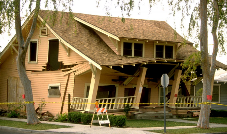
    Most of the damage to a building during an earthquake is caused by lateral movements that disconnect the house from its foundation. Uplift forces can also occur. These lateral loads (shear) and uplift forces due to ground movement need to be transferred to the ground to minimize the likelihood of the building being pulled apart. New homes and existing homes need to be connected to their foundations and the structural elements should be connected to each other to withstand seismic activity.

    Although unrelated to earthquake resistance, when retrofitting a foundation to make it more earthquake resistant, the foundation should also be assessed to see if the insulation, air sealing, and moisture protection could be improved to make the home more thermally efficient and durable.

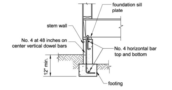
    Building-to-Foundation Connection

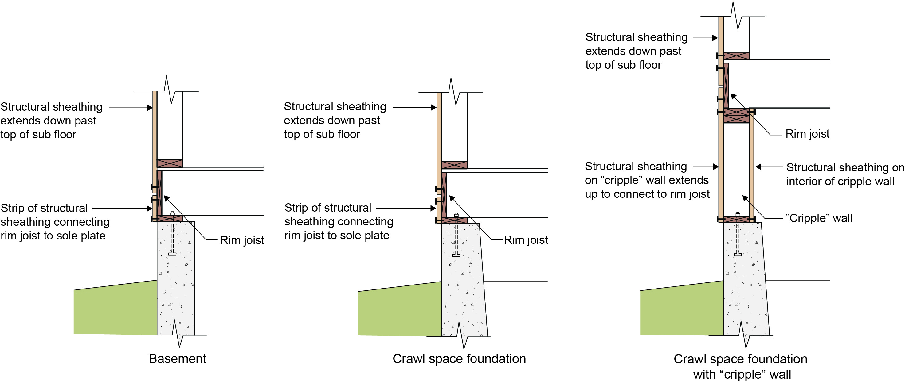
    Figure 1 illustrates the three foundation types covered in this guide: a basement foundation, crawlspace foundation, and crawlspace foundation with a cripple wall. Note in all three foundations the connection of the continuous exterior structural wood sheathing (plywood or oriented strand board “OSB”) to the foundation sill plate. Also, note that the foundation sill plate is connected to the concrete foundation with a foundation anchor bolt. In this manner, the wall and -floor diaphragms are connected to each other and to the foundation.

    Building bracing is provided by the use of continuous exterior structural wood sheathing (plywood or OSB). Note that the crawlspace foundation with a cripple wall has structural wood sheathing on both sides. Main-floor walls are internally reinforced with gypsum sheathing.

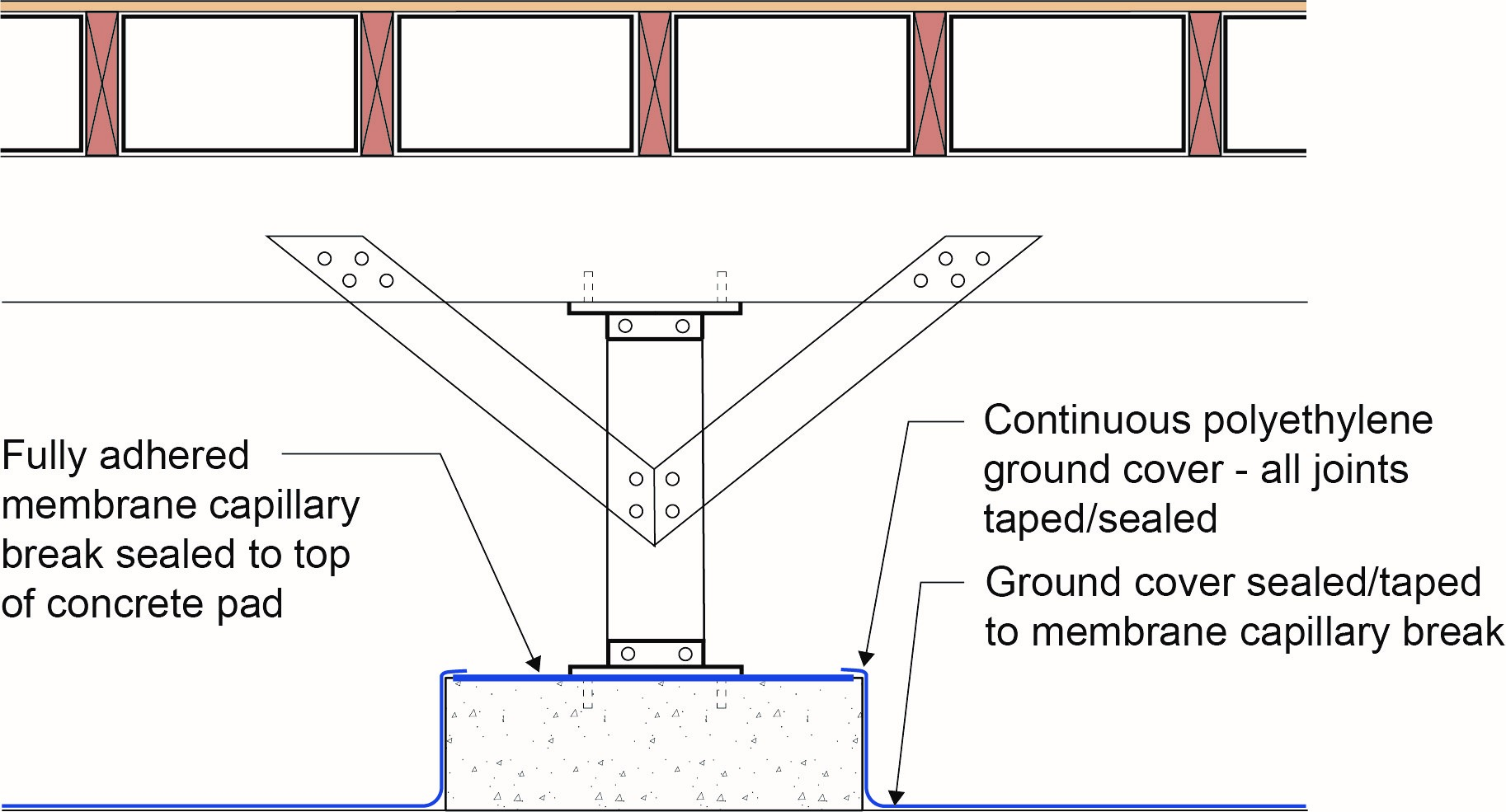
    Additional bracing is provided in both crawlspace assemblies by installing cross bracing at interior posts and piers (Figure 2). 

    All three foundation types should also have solid blocking of dimensional lumber installed between the floor joists. (The blocking is shown in Figure 2 as the white boxes with black outlines between the floor joists.) The solid wood blocking prevents the floor joists from racking or rolling sideways.

    For seismic resistance in basement, crawlspace, and crawlspace “cripple” wall foundations, connect the plywood or OSB sheathing to the wall framing, rim joist, and sill plate and use anchor bolts to tie the sill plate to the foundation
    Figure 1.  For seismic resistance in basement, crawlspace, and crawlspace “cripple” wall foundations, connect the plywood or OSB sheathing to the wall framing, rim joist, and sill plate and use anchor bolts to tie the sill plate to the foundation (Source: Building Science Corporation).​​​​


    Increase the seismic resistance of crawlspace foundations with interior posts by installing cross bracing from the post to the floor beam on both sides of the post. Install solid blocking between the floor joists to prevent the floor joists from “racking” or rolling sideways. (Blocking appears white in drawing; should be made of dimensional lumber.)
    Figure 2. Increase the seismic resistance of crawlspace foundations with interior posts by installing cross bracing from the post to the floor beam on both sides of the post. Install solid blocking between the floor joists to prevent the floor joists from “racking” or rolling sideways. (Blocking appears white in drawing; should be made of dimensional lumber.) (Source: Building Science Corporation). 


    Thermal Efficiency

    New homes and existing homes should be thermally efficient. The basis of all thermal efficiency is to provide environmental separation. Environmental separation requires a continuous water control layer (rain and groundwater), a continuous air control layer (air barrier), a vapor control layer, and a thermal control layer (insulation).

    Basement Foundation

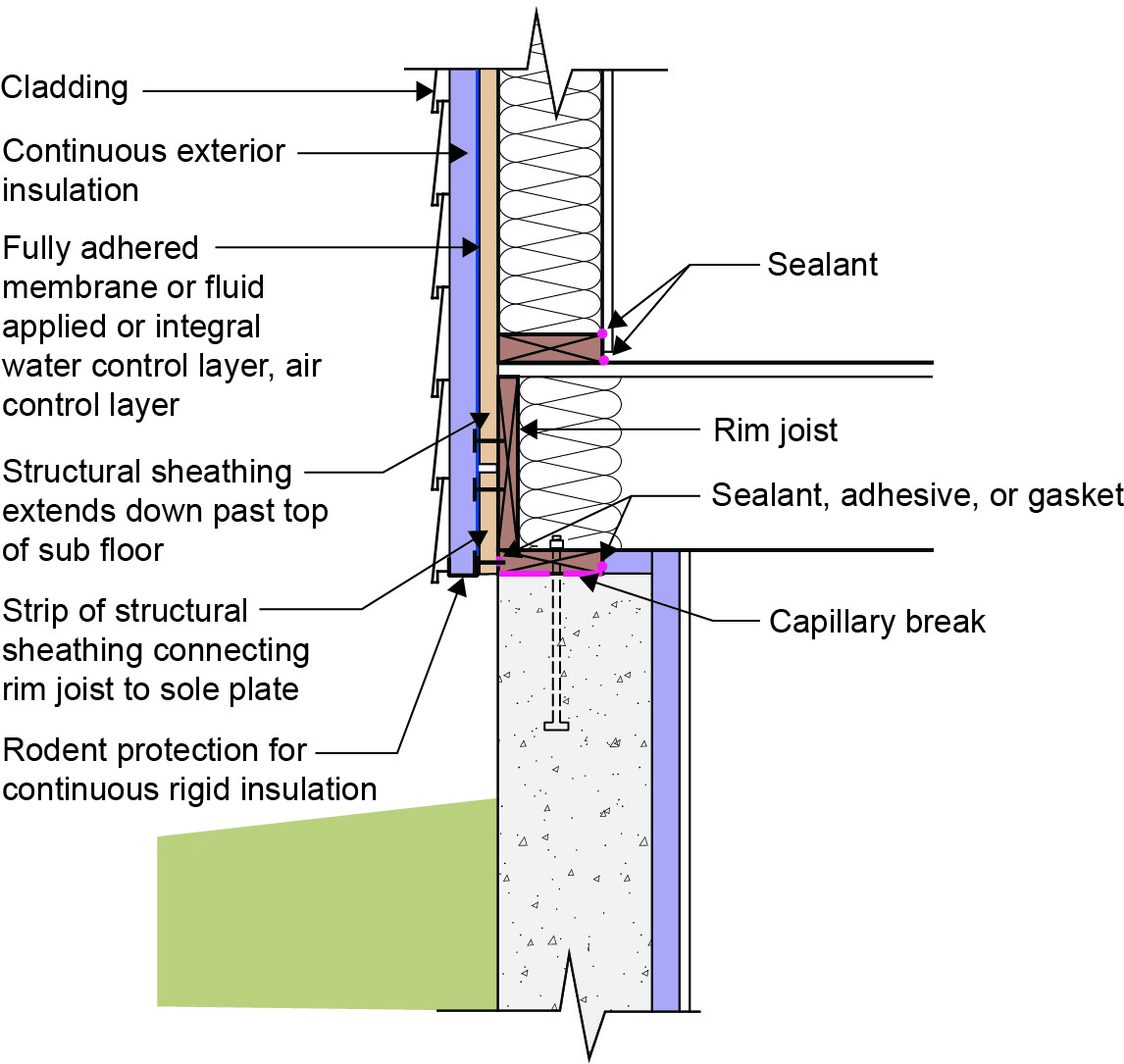
    Figure 3 illustrates one option for installing environmental separation in a basement foundation. In some cases, one product can serve as multiple control layers.

    A continuous water control layer for controlling rainwater is installed on the exterior of the above-grade walls’ structural sheathing; this is connected to the continuous water control layer on the exterior of the basement foundation. This below-grade water control layer, not shown in the figure, could be a fluid-applied waterproofing membrane or dimpled plastic drain mat. A continuous air control layer is installed on the exterior of the above-grade walls’ structural sheathing and is connected to the concrete foundation wall, which is acting as the foundation air control layer. In Figure 3, one product serves as both the water and air control layer. This product could be a fully adhered membrane, a fluid-applied membrane, or house wrap with seams overlapped and taped. The sealed rigid insulation serves as the air control layer on the basement foundation.

    Vapor control is provided by controlling the temperature of the wall assembly condensing surface by installing continuous exterior insulation. Vapor control of the concrete foundation is provided by installing damp proofing on the exterior of the foundation wall and a sheet of polyethylene under the foundation slab.

    Thermal control is provided by installing continuous rigid insulation exterior of the framing and cavity insulation within the wall cavities. Rigid insulation is installed on the interior of the basement foundation wall.

    This approach works in all climates.

    Basement foundation insulated on the interior with rigid foam
    Figure 3. Basement foundation insulated on the interior with rigid foam (Source: Building Science Corporation).


    Crawlspace Foundation

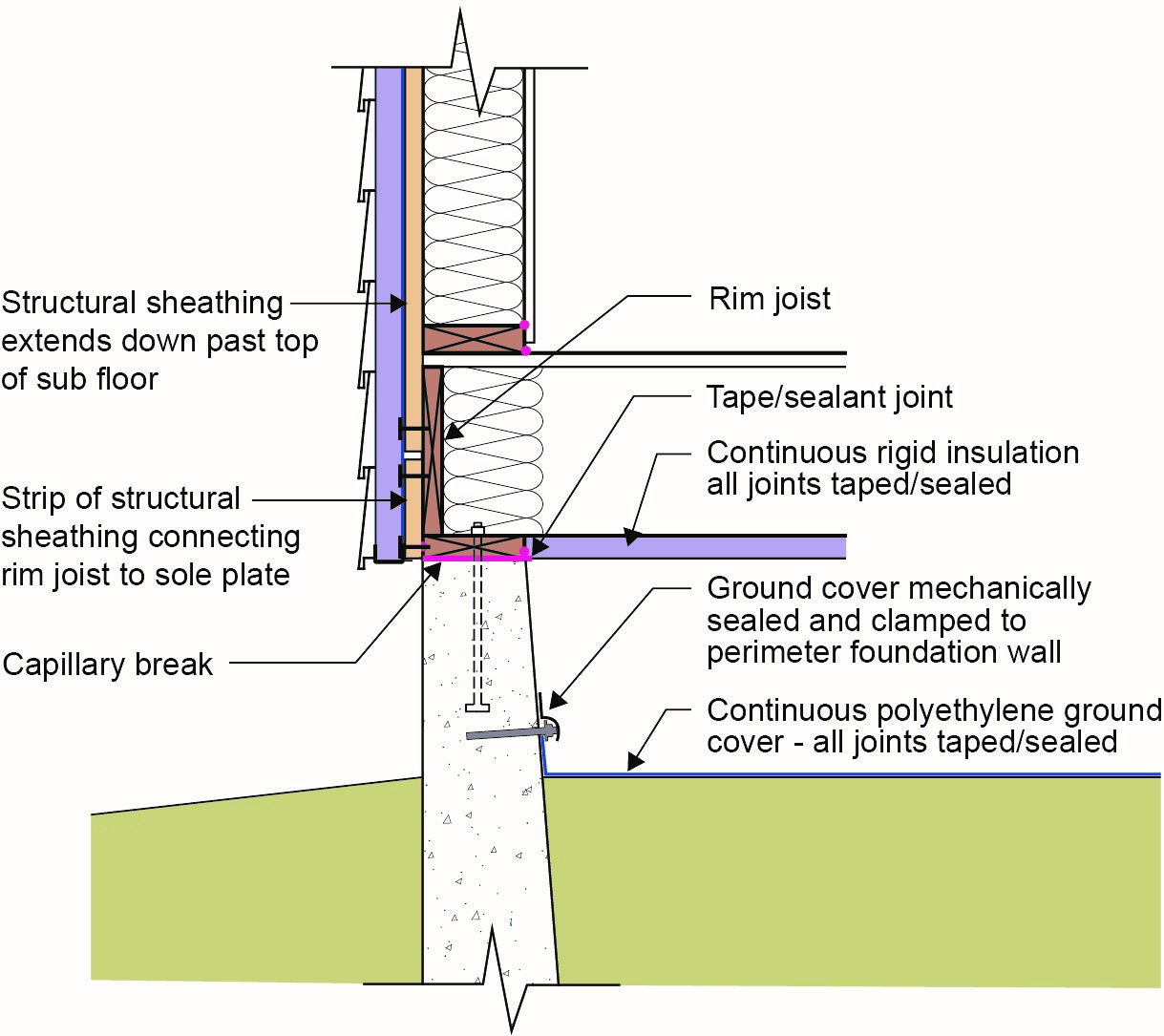
    Figure 4 illustrates one option for insulating vented crawlspaces.   

    A continuous water control layer for controlling rainwater is installed on the exterior of the wall structural sheathing and is connected to the continuous water control layer on the exterior of the concrete foundation stem wall. This water control layer for the above-grade walls could be the rigid foam shown in Figure 4 if the seams are taped and the edges are sealed; it could also be a fully adhered membrane, a fluid-applied membrane, or house wrap with seams overlapped and taped. These products could also serve as the above-grade air barrier. A fluid-applied waterproofing membrane or dimpled plastic drain mat could serve as the water control layer for the below-grade walls.

    The above-grade air control layer is installed on the exterior of the wall structural sheathing and is connected to the top of the concrete foundation stem and in turn to the continuous rigid insulation installed under the floor joists. The continuous rigid insulation under the floor joists is sealed at all seams to act as the air control layer of the insulated floor assembly.

    Vapor control is provided by controlling the temperature of the wall assembly condensing surface by installing continuous exterior insulation. Vapor control of the crawlspace foundation is provided by installing impermeable continuous rigid insulation under the floor joists. Additionally, a continuous polyethylene ground cover is provided.

    Thermal control is provided by installing continuous rigid insulation exterior of the sheathing and cavity insulation within the wall cavities. Additionally, continuous rigid insulation is installed under the floor joists.

    This approach works in all climates.

    Vented crawlspace foundation insulated under floor joists with rigid foam.
    Figure 4. Vented crawlspace foundation insulated under floor joists with rigid foam. (Source: Building Science Corporation).


    Crawlspace Foundation with a Cripple Wall

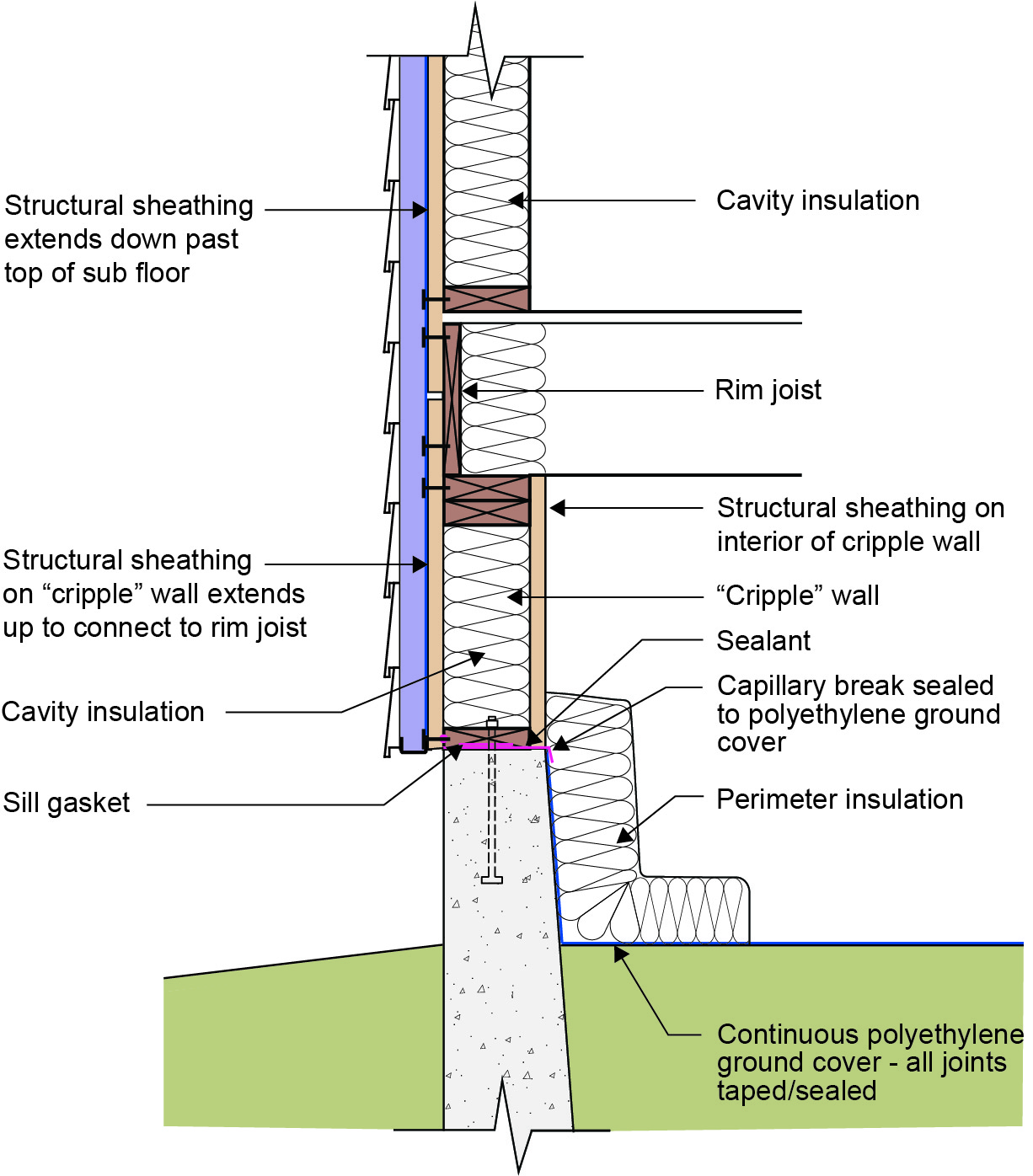
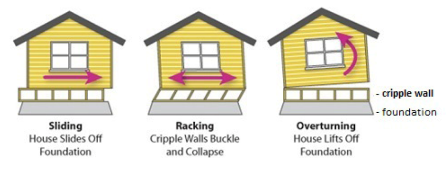
    Figure 5 illustrates one option for insulating an unvented crawlspace foundation with cripple walls. A cripple wall is a short wall that rests on the foundation and supports the floor and exterior walls (Figure 5).

    How to strengthen cripple walls with plywood panels
    Figure 5. How to strengthen cripple walls with plywood panels (Source IBHS 2001).


    A continuous water control layer for controlling rainwater is installed on the exterior of the wall structural sheathing and is connected to the continuous water control layer on the exterior of the concrete foundation stem wall. This water control layer for the above-grade walls could be the rigid foam shown in Figure 6 if the seams are taped and the edges are sealed; it could also be a fully adhered membrane, a fluid-applied membrane, or house wrap with seams overlapped and taped. These products could also serve as the above-grade air barrier. A fluid-applied waterproofing membrane or dimpled plastic drain mat could serve as the water control layer for the below-grade walls.

    The above-grade air control layer is installed on the exterior of the wall structural sheathing and is connected to the top of the concrete foundation stem wall and in turn to a continuous polyethylene ground cover that is extended up the interior of the concrete foundation stem wall.

    Vapor control is provided by controlling the temperature of the wall assembly condensing surface by installing continuous exterior insulation. Vapor control of the crawl space foundation is provided by installing a continuous polyethylene ground cover that is extended up the interior of the concrete foundation stem wall. Figure 7 illustrates continuity of the air and vapor control layers at the interior posts and piers.

    Thermal control is provided by installing continuous rigid insulation exterior of the sheathing and cavity insulation in the wall cavities. Additionally, foil-faced or plastic-faced batt insulation is installed on the interior of the concrete foundation stem wall and extends horizontally over the polyethylene ground cover at the perimeter of the crawl space.

    This approach works in all climates with the following limitation – in Climate Zones 5 and higher, the foil-faced or plastic-faced batt or roll insulation must be replaced with impermeable rigid insulation or closed cell spray polyurethane foam.

    Insulating a crawlspace foundation with a cripple wall in warm climates; in Climate Zones 5+ replace the foil- or plastic-faced fiberglass batt insulation with impermeable rigid insulation or closed-cell spray polyurethane foam
    Figure 6. Insulating a crawlspace foundation with a cripple wall in warm climates; in Climate Zones 5+ replace the foil- or plastic-faced fiberglass batt or roll insulation with impermeable rigid insulation or closed-cell spray polyurethane foam (Source: Building Science Corporation).


    The polyethylene ground cover in the crawl space is lapped up sides of piers to posts to provide a continuous air and vapor barrier
    Figure 7. The polyethylene ground cover in the crawl space is lapped up sides of piers to posts to provide a continuous air and vapor barrier (Source: Building Science Corporation).


    Success
    Ensuring Success

    Consult a licensed architect or engineer to develop a detailed design and approach for the home to withstand seismic activity. Thermal efficiency should be incorporated as required by code.

    Climate
    Climate

    Earthquake Areas

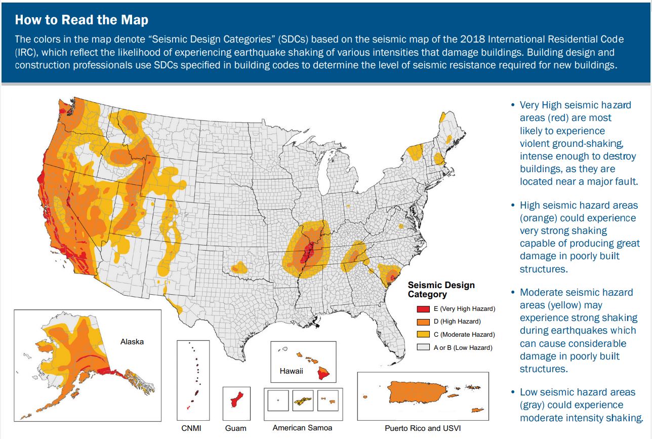
    The approaches to seismic control will work in all climates. However, check local building codes for specific requirements as seismic risk and requirements vary based on location; see map below. Insulation requirements for thermal efficiency are climate dependent; see the Compliance tab and consult local code for requirements. 

    The International Residential Code (IRC) takes a building’s seismic risk into account based on location. The IRC contours the United States into seismic design categories, from low risk to high risk as shown in Figure 1, which designates the categories by letter: A, B, C, D0, D1, D2, and E, with A designating the lowest risk and E designating areas with the highest risk. The IRC has design guidelines for categories A through D2 as well as scenarios for when a building in design category E can be reassigned to category D2. If a building located in design category E cannot be reassigned to category D2, then it must be designed using the International Building Code (IBC), not the IRC.

    Seismic map of the 2018 International Residential Code adapted by FEMA to show Seismic Design Categories in color
    Figure 1. Seismic map of the 2018 International Residential Code adapted by FEMA to show Seismic Design Categories in color (Source: FEMA 2020). 


    Training
    Right and Wrong Images
    Image
    How to properly anchor a new home to its foundation with foundation sill plate, stem wall, and footing
    How to properly anchor a new home to its foundation with foundation sill plate, stem wall, and footing
    Image
    How to strengthen cripple walls with plywood panels.
    How to strengthen cripple walls with plywood panels.
    Image
    The cripple walls in this home gave way in the 1994 Northridge Earthquake, causing the walls to partially collapse.
    The cripple walls in this home gave way in the 1994 Northridge Earthquake, causing the walls to partially collapse.
    Image
    To increase a masonry-walled home’s resistance to seismic forces, solid wood blocking is added between the roof rafters, anchors are added to connect the brick wall to the rafters and floor joists, building diaphragms are added, foundation braced
    To increase a masonry-walled home’s resistance to seismic forces, solid wood blocking is added between the roof rafters, anchors are added to connect the brick wall to the rafters and floor joists, building diaphragms are added, foundation braced
    Image
    For seismic resistance in basement, crawlspace, and crawlspace “cripple” wall foundations, connect the plywood or OSB sheathing to the wall framing, rim joist, and sill plate and anchor bolt the sill plate to the foundation
    For seismic resistance in basement, crawlspace, and crawlspace “cripple” wall foundations, connect the plywood or OSB sheathing to the wall framing, rim joist, and sill plate and anchor bolt the sill plate to the foundation
    Image
    Possible failure scenarios due to house sitting on poorly braced and secured cripple wall
    Possible failure scenarios due to house sitting on poorly braced and secured cripple wall
    Image
    Wrong – The cripple wall beneath this house failed in an earthquake
    Wrong – The cripple wall beneath this house failed in an earthquake
    Image
    The cripple wall hiding the post-and-pier foundation of this wood framed house toppled when the house was shifted partially off its piers by an earthquake
    The cripple wall hiding the post-and-pier foundation of this wood framed house toppled when the house was shifted partially off its piers by an earthquake
    Image
    The cripple walls in this home gave way in the 1994 Northridge Earthquake, causing the walls to partially collapse.
    The cripple walls in this home gave way in the 1994 Northridge Earthquake, causing the walls to partially collapse.
    Image
    Right – Spray foam insulation was sprayed onto the ground and along the sides of the foundation walls and piers of this insulated crawl space.
    Right – Spray foam insulation was sprayed onto the ground and along the sides of the foundation walls and piers of this insulated crawl space.
    Image
    Right - Rigid foam board is attached to the interior surface of the basement walls.
    Right - Rigid foam board is attached to the interior surface of the basement walls.
    Compliance

    Compliance

    The Compliance tab contains both program and code information. Code language is excerpted and summarized below. For exact code language, refer to the applicable code, which may require purchase from the publisher. While we continually update our database, links may have changed since posting. Please contact our webmaster if you find broken links.

    ENERGY STAR Single-Family New Homes, Version 3/3.1 (Rev. 11)

    ENERGY STAR Single-Family New Homes requires that ceiling, wall, floor, and slab insulation levels meet or exceed those specified in the International Energy Conservation Code (IECC) (2009 IECC for Version 3.0 and 2012 IECC for Version 3.1), with some alternatives and exceptions, and achieve Grade 1 installation per RESNET Standards. Builders must also meet or exceed the locally mandated requirements. Visit the U.S. DOE Building Energy Codes Program to see what code has been adopted in each state.

    Please see the ENERGY STAR Single-Family New Homes Implementation Timeline for the program version and revision currently applicable in your state.

    DOE Zero Energy Ready Home (Revision 07)

    Exhibit 1 Mandatory Requirements.
    Exhibit 1, Item 1) Certified under the ENERGY STAR Qualified Homes Program or the ENERGY STAR Multifamily New Construction Program.
    Exhibit 1, Item 2) Ceiling, wall, floor, and slab insulation shall meet or exceed 2015 IECC levels and achieve Grade 1 installation, per RESNET standards.

    2009201220152018, and 2021 International Residential Code (IRC)

    Section 301.2.2 Seismic Provisions. Discusses determination of seismic design categories based on building location. See the seismic map on the Climate tab.

    Section R403 provides details on footings including reinforcement requirements for footings based on Seismic Design Categories A-C and D0, D1, and D2.

    Section R403.1.6 discusses foundation anchorage

    [Seismic Categories A and B]

    Wood sole plates at all exterior walls on monolithic slabs, wood sole plates of braced wall panels at building interiors on monolithic slabs, and all wood sill plates shall be anchored to the foundation with minimum ½-inch-diameter anchor bolts spaced not greater than 6 feet on center or approved anchors or anchor straps spaced as required to provide equivalent anchorage to ½-inch-diameter anchor bolts. Bolts shall extend at least 7 inches into the concrete or grouted cells of concrete masonry units. The bolts shall be located in the middle third of the width of the plate. A nut and washer shall be tightened on each anchor bolt. There shall be at least two bolts per plate section with one bolt located no more than 12 inches and no less than seven bolt diameters (≥3.5 inches) from each end of the plate section… (see code for additional details).

    Section R403.1.6.1 Foundation Anchorage in Seismic Design Categories C. D0, D1, and D2

    In addition to the requirements of Section R403.1.6, the following requirements shall apply to wood light-frame structures in Seismic Design Categories D0, D1, and D2, and wood light-frame townhouses in Seismic Design Category C.

    1. Plate washers conforming to Section R602.11.1 shall be provided for all anchor bolts over the full length of required braced wall lines except where approved anchor straps are used. Properly sized cut washers shall be permitted for anchor bolts in wall lines not containing braced wall panels. (See code for additional details.)

    R602.9 discusses cripple walls.

    Table R602.10.3(3) gives bracing requirements based on seismic design category.

    Section R602.10.10 discusses cripple wall bracing.

    Section R602.11 discusses wall anchorage.

    2009201220152018, and 2021 International Energy Conservation Code (IECC)

    Minimum Insulation Requirements: The minimum insulation requirements for ceilings, walls, floors, and foundations in new homes, as listed in the 2009, 12, 15, 18, and 21 IECC and IRC, can be found in this table.

    Retrofit: 2009201220152018, and 2021 IECC

    Section R501.1.1 in 2018 IRC. Additions, alterations, renovations, or repairs shall conform to the provisions of this code, without requiring the unaltered portions of the existing building to comply with this code. (See code for additional requirements and exceptions.)

    Retrofit
    Existing Homes

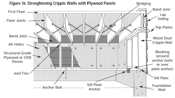
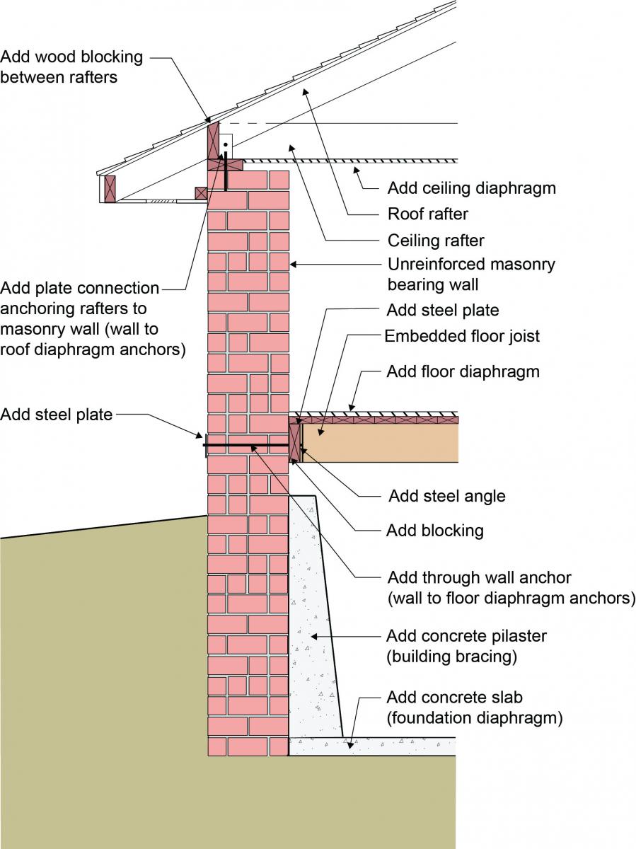
    The approach to seismic retrofit is the same as the approach to new design for seismic resistance. The basis of all earthquake resistance is to control and transfer lateral loads (“sheer”) caused by ground movement to foundations and the ground. The Earthquake Overview guide in the Building America Solution Center provides extensive guidance on retrofitting measures to strengthen cripple walls.

    More

    More Info.

    Access to some references may require purchase from the publisher. While we continually update our database, links may have changed since posting. Please contact our webmaster if you find broken links.

    References and Resources*
    Author(s)
    California Seismic Safety Commission
    Organization(s)
    SSC
    Publication Date
    Description
    Guidebook that provides information on earthquake hazards that can damage homes, the design and retrofit of earthquake resistant housing, and how to find more information on earthquake safety.
    Author(s)
    Lstiburek Joseph W
    Organization(s)
    Building Science Corporation,
    BSC
    Publication Date
    Description
    Information sheet with methods for constructing or retrofitting basements to reduce moisture issues.
    Author(s)
    Lstiburek Joseph W
    Organization(s)
    Building Science Corporation,
    BSC
    Publication Date
    Description
    Article discussing whether or not to seal and insulate crawlspaces.
    Author(s)
    Building Seismic Safety Council
    Organization(s)
    BSSC,
    National Institute of Building Sciences,
    NIBS,
    Federal Emergency Management Agency,
    FEMA,
    National Earthquake Hazards Reduction Program,
    NEHRP
    Publication Date
    Description
    Document presenting the minimum recommended requirements necessary for the design and construction of new buildings and other structures to resist earthquake ground motions throughout the United States.
    Author(s)
    Federal Emergency Management Agency
    Organization(s)
    FEMA
    Publication Date
    Description
    Guide provides homeowners ways to prepare for an earthquake and protect a home against earthquake damage.
    *For non-dated media, such as websites, the date listed is the date accessed.
    Contributors to this Guide

    The following authors and organizations contributed to the content in this Guide.

    Building Science Corporation

    Pacific Northwest National Laboratory

    Last Updated

    Did you find this information helpful?

    If you have questions and/or would like a reply to this feedback, please include your e-mail address in the message.
    This question is for testing whether or not you are a human visitor and to prevent automated spam submissions.