

Scope
Install flashing integrated with air and water control layers around piping, vents, and other wall penetrations as part of an exterior wall retrofit as follows:
- Remove the existing cladding and trim. Prepare the wall sheathing to receive the air/water control membrane.
- Install a continuous air/water control membrane (such as house wrap, fully adhered membrane or liquid applied membrane) with a hole for the vent or pipe.
- Apply a bead of sealant around the duct/pipe penetration.
- Install insulating sheathing and vertical wood furring strips.
- Install sheathing tape flashing and wood blocking for trim.
- Install a trim block over the duct/pipe and install the metal cap flashing.
- Install a vent hood/cap.
- Install wall cladding and trim. Attach to furring strips.
For more on roof/wall connections, see the U.S. Department of Energy’s Standard Work Specifications.
See the Compliance Tab for links to related codes and standards and voluntary federal energy-efficiency program requirements.
Description
When an exterior wall is being upgraded by removing exterior cladding, there are several elements within the field of the wall that “interrupt” the wall assembly, such as pipes, vents, wiring, windows, doors, and architectural elements. While these elements are needed for functional reasons and to add character and amenity to buildings, they can complicate the continuity of the building enclosure functions, including the air, water, vapor, and thermal control layers.
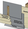
In most walls, a water control layer protects the structure. Water control layers are water-repellent materials (building paper, house wrap, sheet membranes, liquid-applied coatings, or taped and sealed rigid insulation boards) that are located behind the cladding (the siding) and are designed and constructed to protect the wall sheathing by from any rain water that might get through the cladding. Water control layers are interconnected with metal and flexible flashing s around windows, doors, and other penetrations through the building enclosure to provide a continuous path to drain water to the exterior of the building. The materials that form the water control layer overlap in a shingle fashion or are sealed so that water drains down and out of the wall. The water control layer is often referred to as the drainage plane, the water-resistive barrier (WRB), or the water control layer.
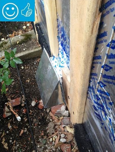
Protection is typically provided by flashings which might be metal as shown in Figure 1 or self-adhering flexible flashing tape). Flashings are the most underrated of building enclosure components and are arguably the most important. Flashings are integrated with the water control layer, creating for all practical purposes a flashing for the entire assembly. Flashings are needed wherever a drainage plane is terminated as at a roof edge or the bottom of a wall, or where the drainage plane is interrupted as at openings, the intersection of assemblies, control joints, or penetrations of the drainage plane.
Figures 2 to 7 show detail drawing for several air sealing details. These figures show how to do these air sealing details as part of an exterior wall retrofit that includes adding rigid foam insulating sheathing to the wall. . The air sealing procedures work equally well in the absence of the insulating sheathing.

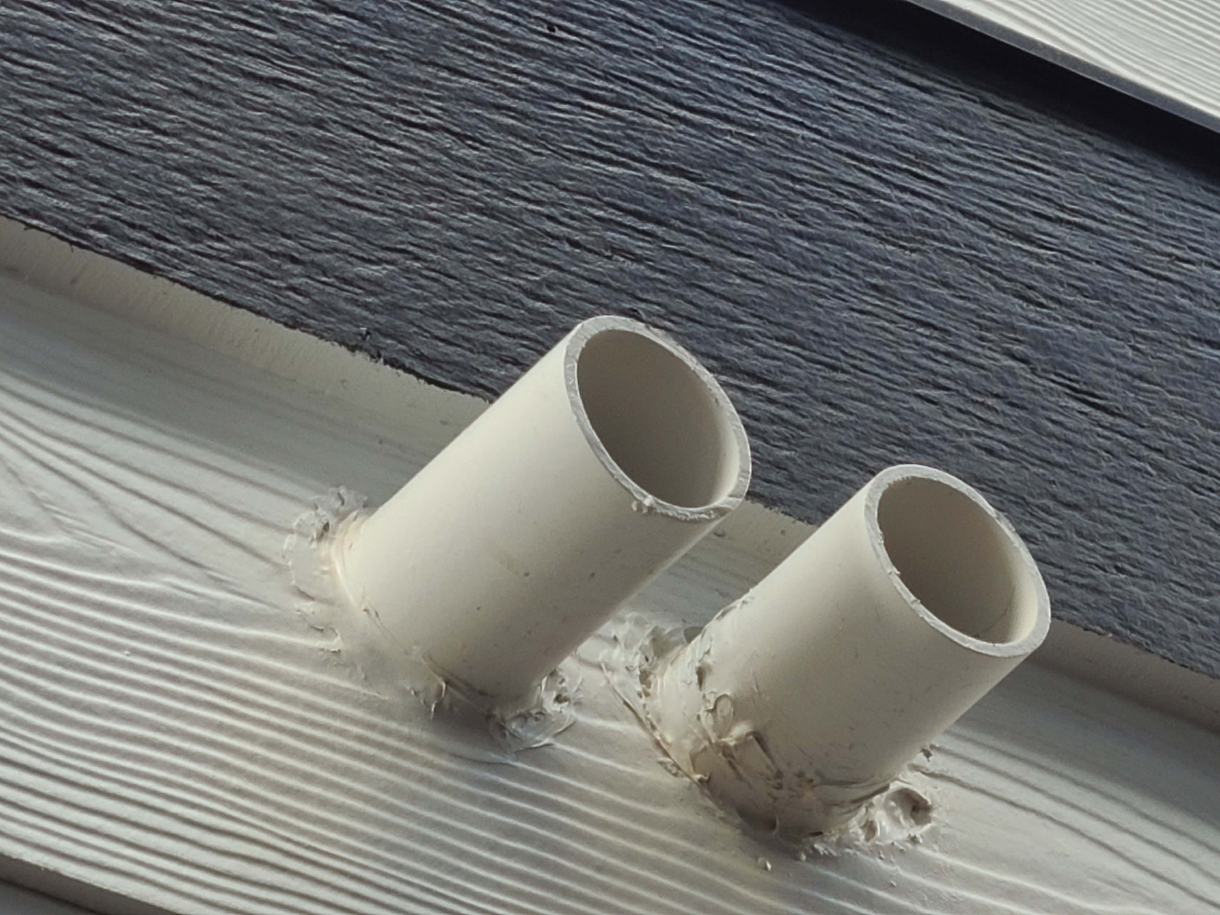
Duct/Pipe Penetration
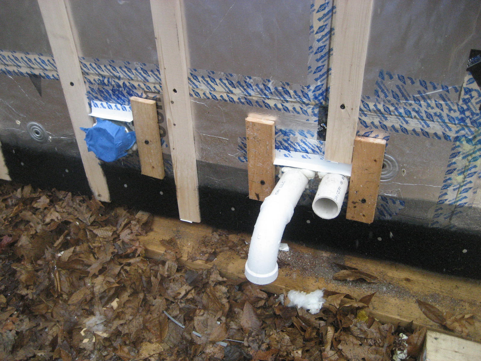
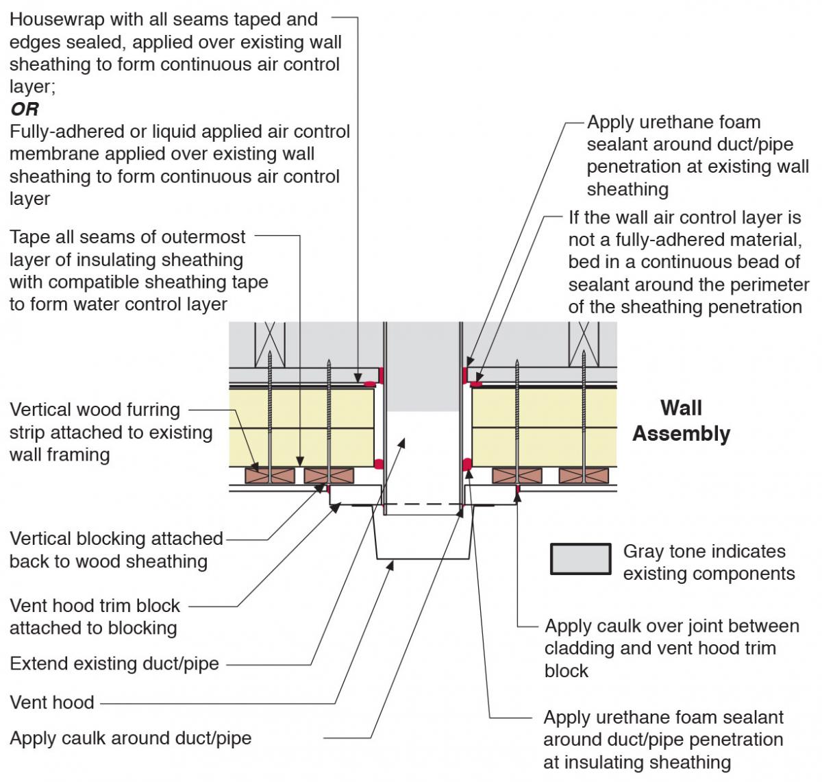
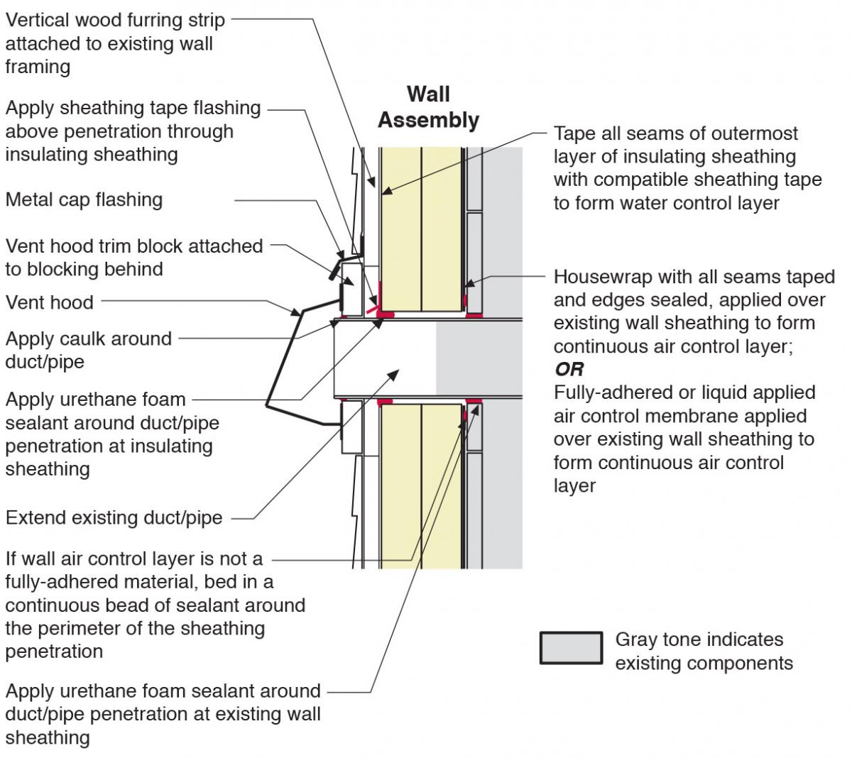
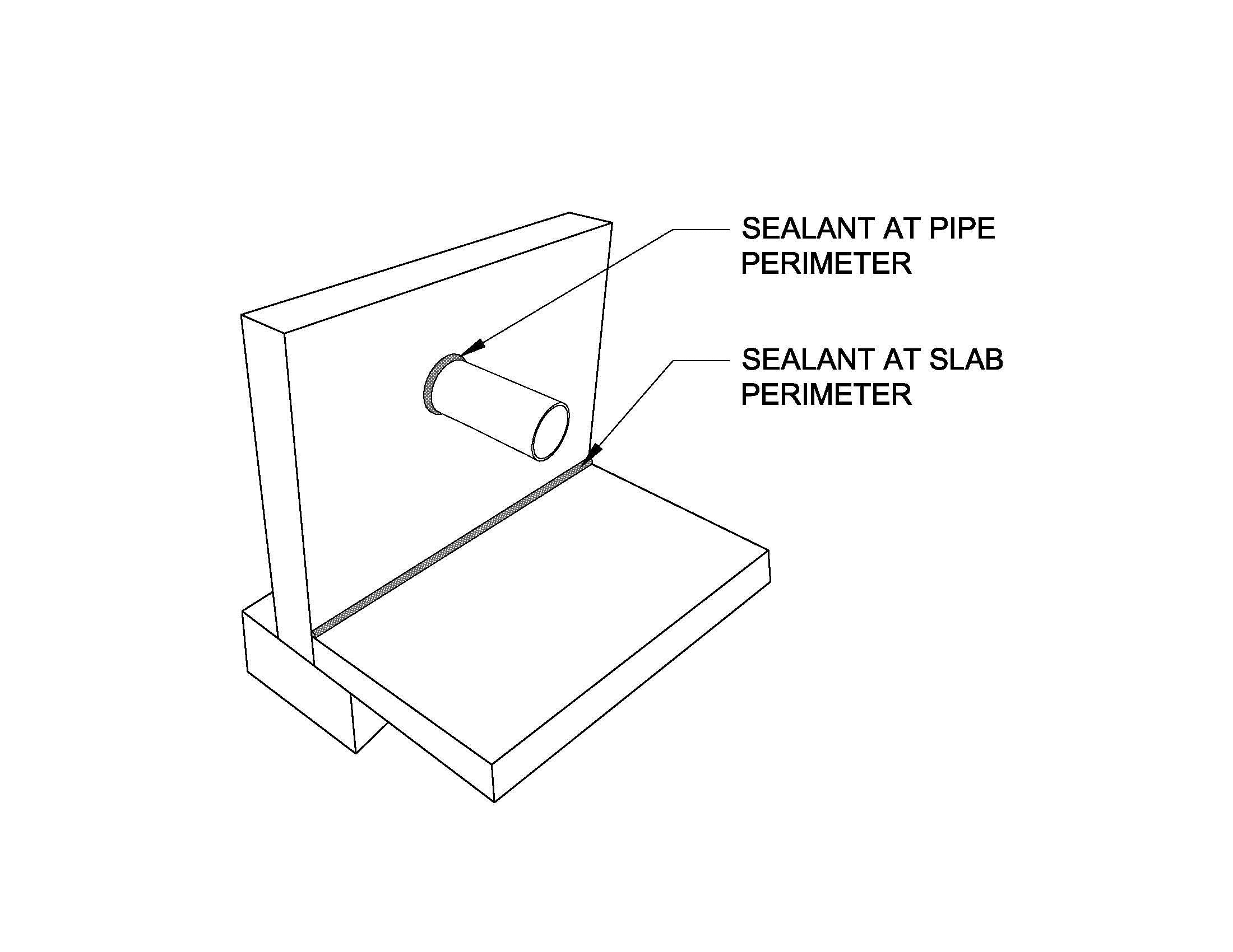
Figures 2 and 3 show the proper locations to apply sealant, tape flashing, and metal flashing around a pipe that extends through an exterior wall. In the case shown in Figures 2 and 3, the wall has been retrofitted by installing (over the existing wall sheathing) house wrap, two layers of rigid foam, wood furring strips, and new siding. In this case, the pipe is extended to accommodate the thicker wall, and a vent hood is attached over the end of the pipe. Figure 2 is a plan or overhead view of the pipe sealing detail and Figure 3 is a section or side view of the same detail.
For more information on sealing around pipes, see the guide Plumbing Piping.
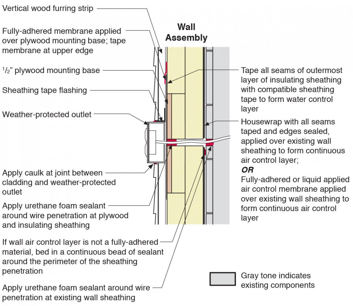
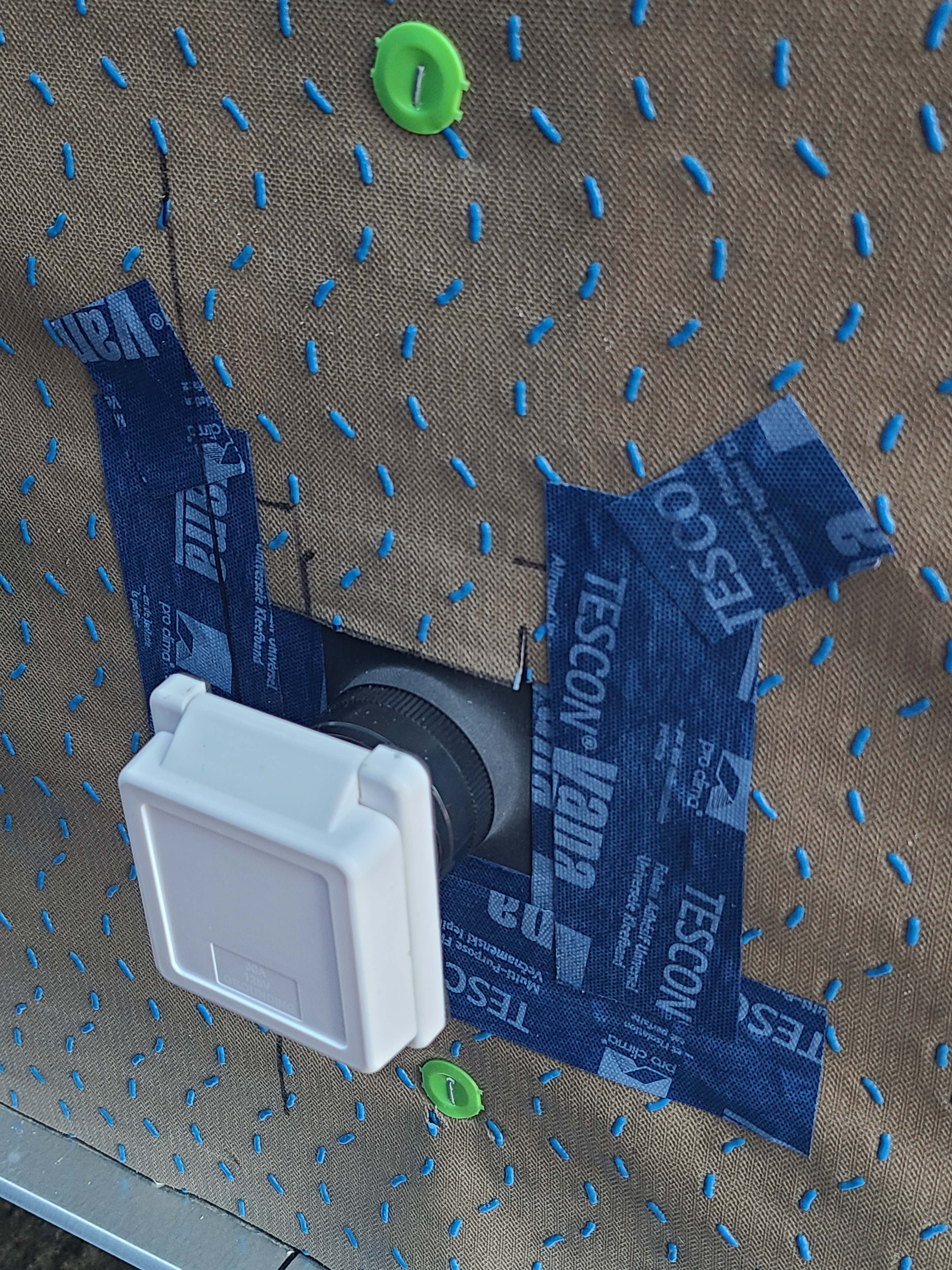
Exterior Electric Box
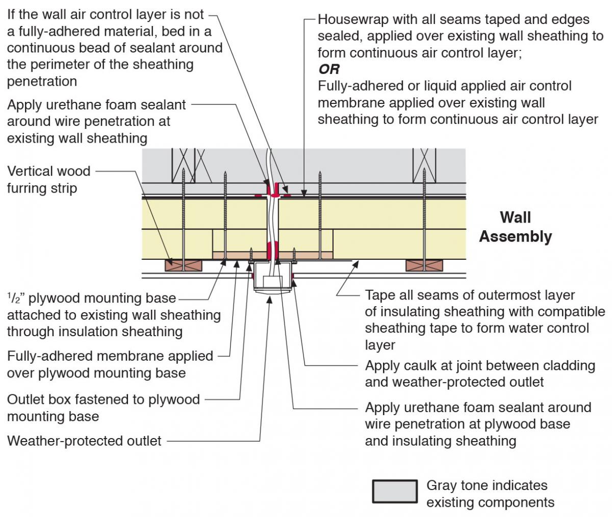
Figures 4 and 5 show the proper locations to apply foam and caulk sealant and tape flashing around an electrical box that is installed in an exterior wall. In the case shown in Figures 4 and 5, the wall has been retrofitted by installing (over the existing wall sheathing) house wrap, two layers of rigid foam, wood furring strips, and new siding. Figure 4 is a plan view and Figure 5 is a section view of the same detail.
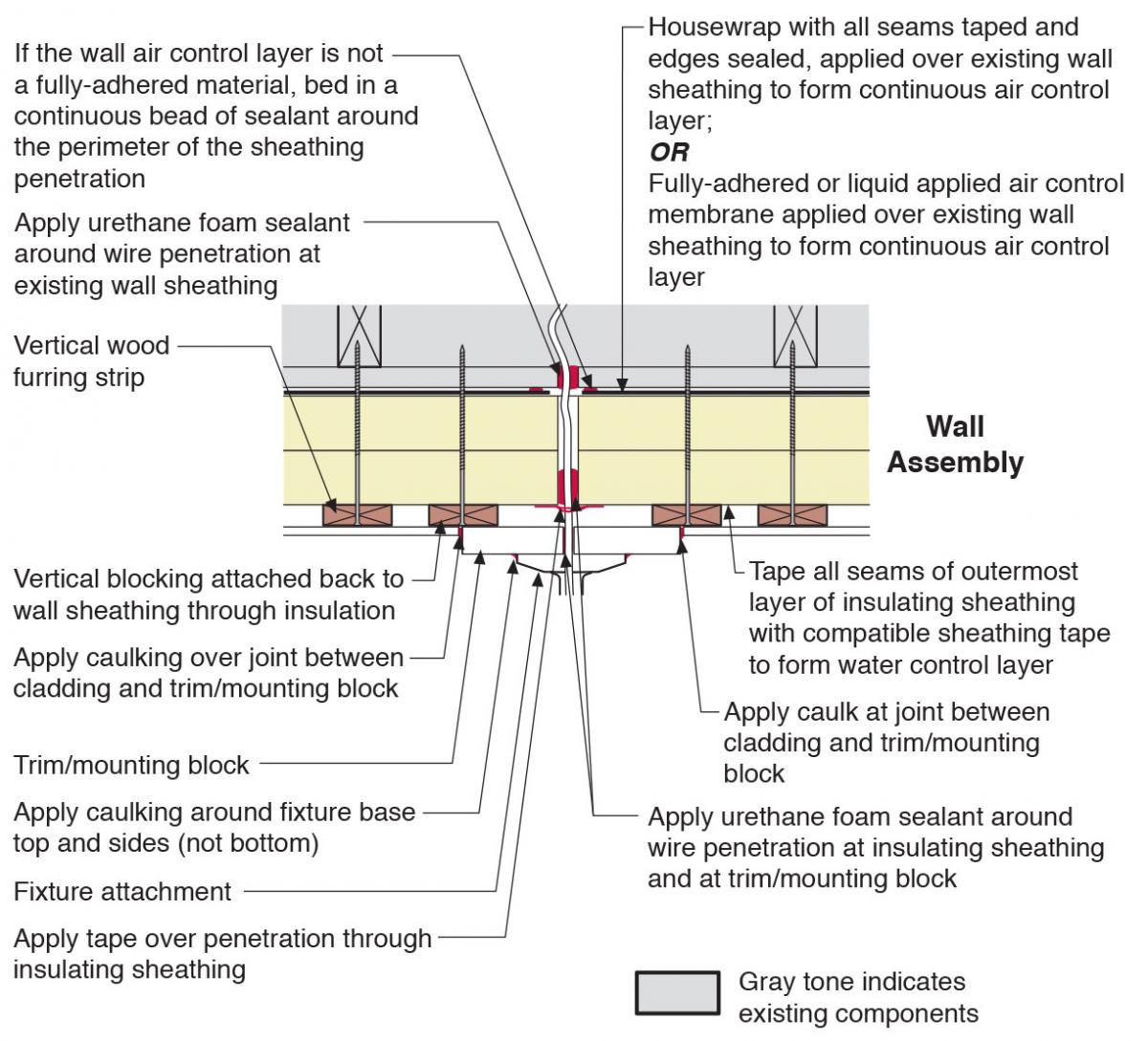
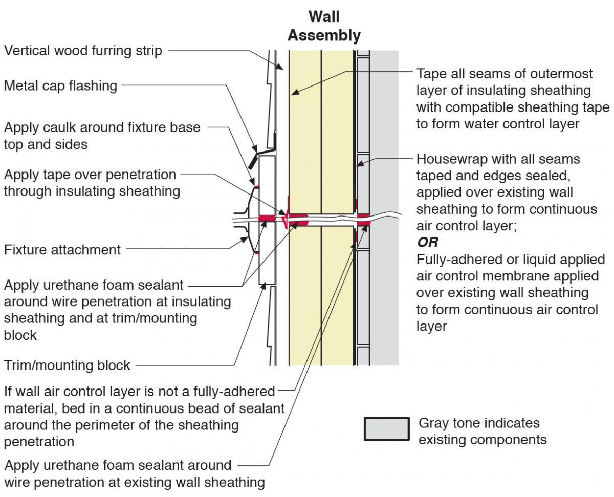
Trim Block with Wire Penetration
Figures 6 and 7 show the proper locations to apply foam and caulk sealant and tape and metal flashing around the wiring and trim block installed in an exterior wall to mount an exterior light fixture. In the case shown in Figures 6 and 7, the wall has been retrofitted by installing (over the existing wall sheathing) house wrap, two layers of rigid foam, wood furring strips, and new siding. Figure 6 is a plan view and Figure 7 is a section view of the same detail.
How to Water Manage Wall Penetrations
Remove the existing wall cladding (see Step 1). Prepare the wall sheathing to receive the air/water control membrane. Appropriate preparation of the wall sheathing will depend upon the nature of the existing sheathing and the air control strategy to be pursued. If using a sheet good like house wrap as the air/water control layer, all protruding fasteners must be removed to avoid punctures or tears in the membrane. Gaps or voids in the sheathing layer may need to be filled in.
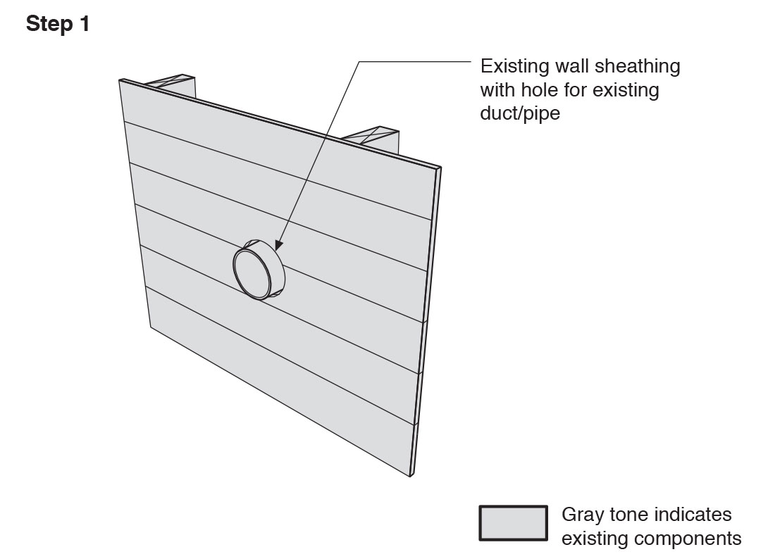
Step 1. Remove the existing wall cladding to prepare to retrofit an exterior wall. (Source: Building Science Corporation.) Install a continuous air/water control membrane (building paper, house wrap, sheet membranes, liquid-applied coatings, or taped and sealed rigid insulation boards). Carefully cut holes for any ducts, pipes, or other penetrations. Make holes no larger than necessary. If the air control layer is not a fully adhered material, install a continuous bead of sealant on the existing sheathing around the penetration prior to installing the water control layer (see Step 2).
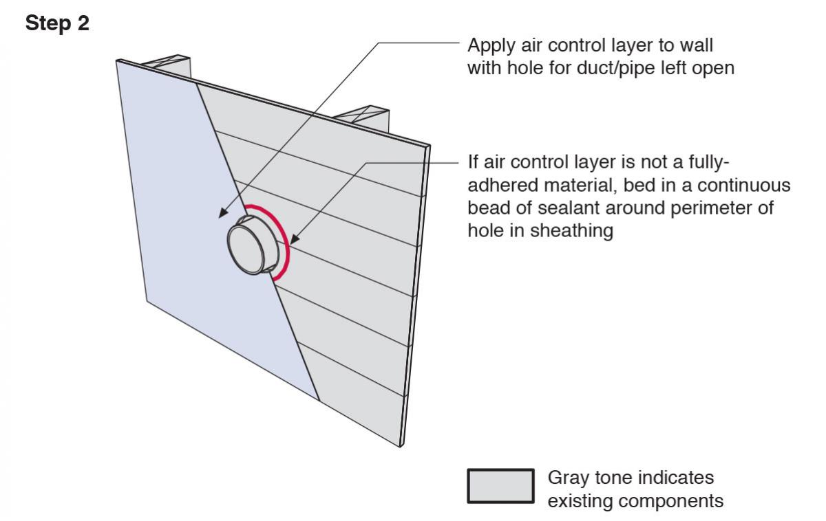
Step 2. Install a continuous air and water control layer over the existing wall sheathing. (Source: Building Science Corporation.) Apply a generous bead of urethane sealant, applied similar to caulk, around the duct, pipe, or wiring. If rigid foam sheathing will be installed over the wall, extend the duct pipe if needed so that it will stand 2 inches proud of the insulating sheathing.
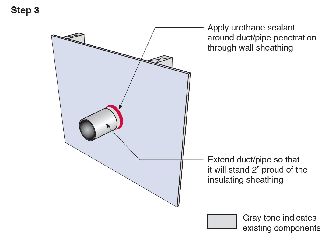
Step 3. Apply urethane sealant around the duct or pipe in the retrofitted exterior wall. (Source: Building Science Corporation.) Install insulating sheathing with joints offset horizontally and vertically and the joints of the outermost layer taped. Attach wood furring strips through the insulating sheathing to the wall studs. Install furring strips in a vertical orientation only. Apply a bead of urethane sealant around the duct, pipe, or wiring at the insulating sheathing.
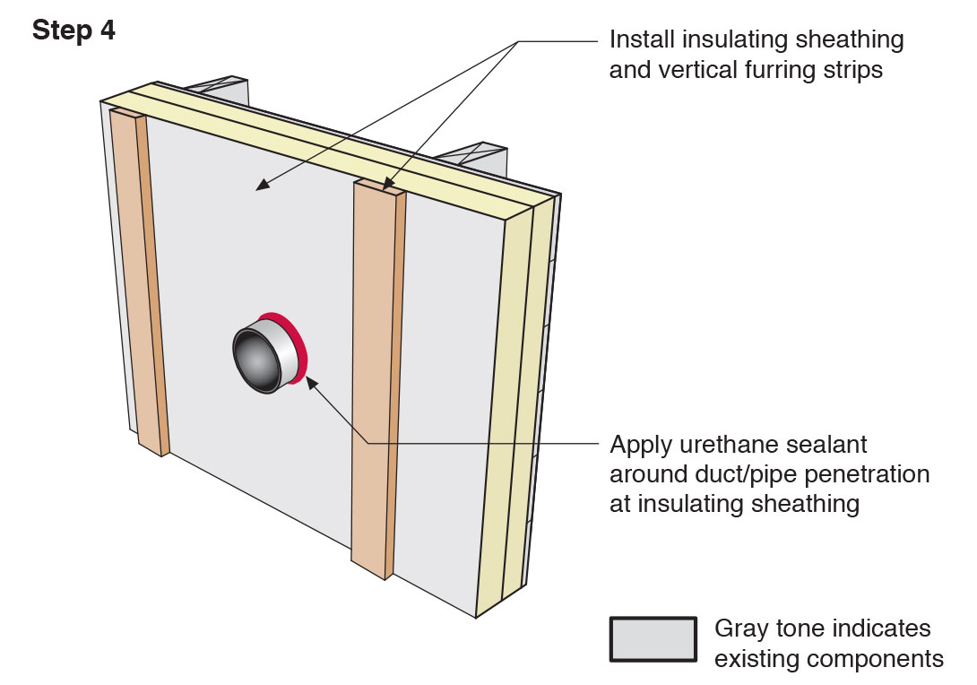
Step 4. Install insulating sheathing and vertical furring strips on the retrofitted exterior wall; seal around pipe or duct with urethane sealant. (Source: Building Science Corporation.) Install sheathing tape flashing above the duct/pipe penetration. Attach wood blocking for trim on each side of the pipe, duct, or wiring. The fasteners should extend through the insulating foam to the existing wood sheathing.
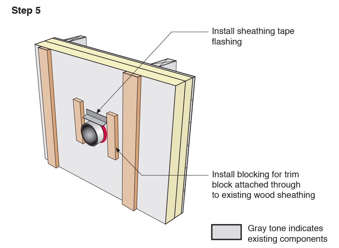
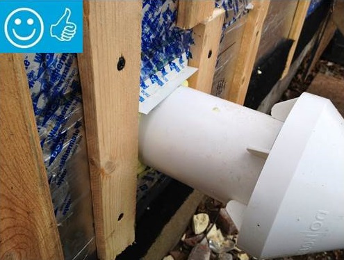
Step 5. Install sheathing tape flashing over the duct or pipe and wood blocking on either side for later attachment of trim. (Source: Building Science Corporation.) Install the vent hood trim block over the duct/pipe and install the metal cap flashing with a drip edge over the trim. Tape the top edge of the metal cap flashing with sheathing tape.
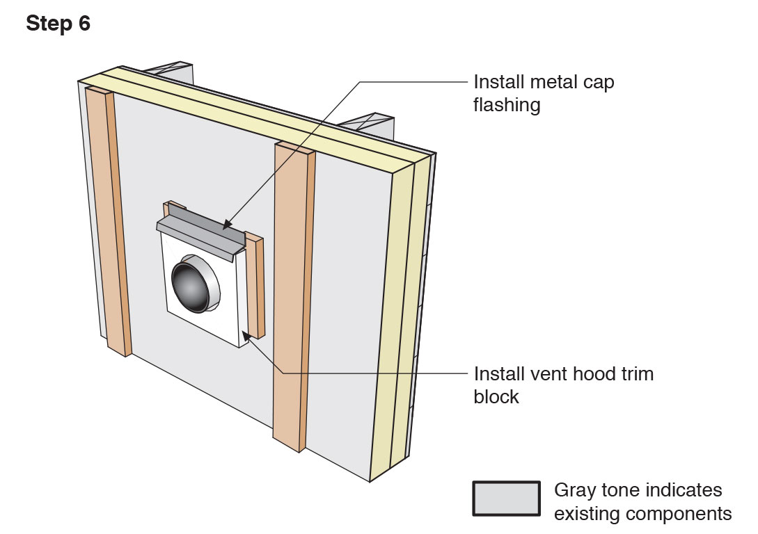
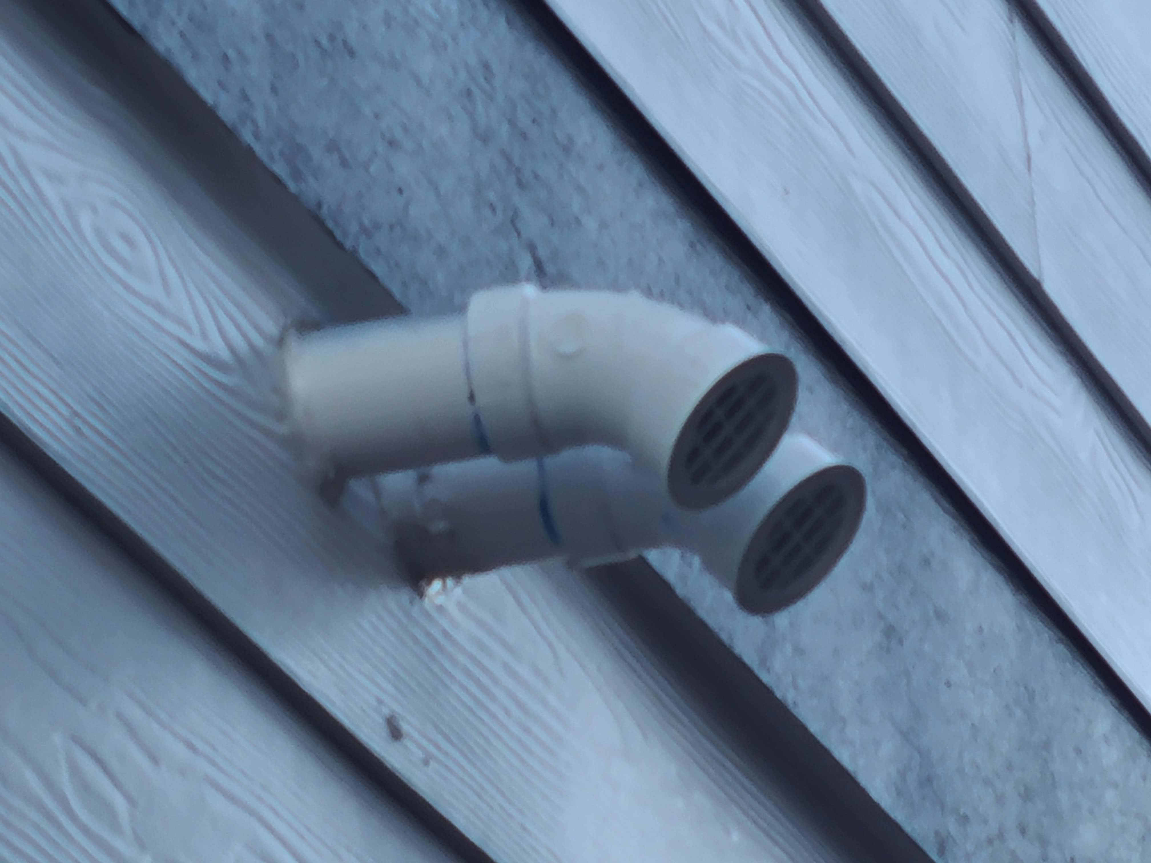
Step 6. Install vent hood trim block, metal cap flashing; seal top edge of flashing with sheathing tape. (Source: Building Science Corporation.) Install the vent hood over the end of the duct or pipe to keep out rain and snow. Clothes dryer vents should have self-closing louvers. Other vent and pipe openings should be covered with .5x.5 inch metal mesh screens or .25x.25 hardware cloth screening to keep out rodents, birds, and bats.
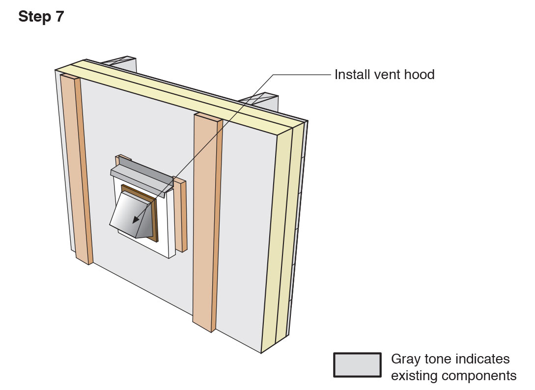
Step 7. Install a vent hood on the pipe to keep out rain. (Source: Building Science Corporation.) Attach the new cladding to the furring strips to complete the exterior wall retrofit.
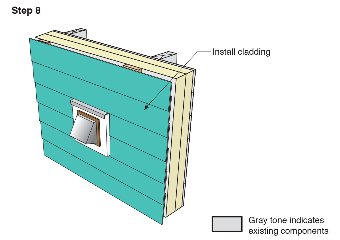
Step 8. Attach the new cladding to the furring strips over the rigid foam for the exterior wall retrofit. (Source: Building Science Corporation.)
Ensuring Success
- Install the materials that form the water control layer in a shingle fashion so they overlap each other and/or are sealed to allow for the water to drain down and out of the wall.
- Use mounting blocks for all penetrations.
- Remediate any hazardous conditions that will be affected (e.g., exposed or aggravated) by the planned work. (For example, does the existing siding have lead paint?)
- Follow applicable laws and industry procedures for mitigation of hazardous materials.
- Engage the services of a qualified professional when needed.
Region
In hurricane and high-wind prone areas, note that wind can drive rain horizontally and even upwardly against exterior wall surfaces. In these regions, consider extended flashing and redundant flashing and air sealing practices at all penetrations through exterior walls, including around doors, windows, vents, etc.
Training
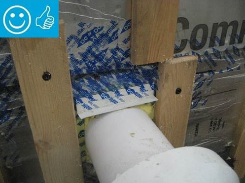
Right and Wrong Images
Source
Source
Source
Source

Source
Source

Source
Source
Source
Source
Source
Source
Source
Videos


More Info
References and Resources
*For non-dated media, such as websites, the date listed is the date accessed.
Contributors to this Guide
The following authors and organizations contributed to the content in this Guide.
Sales
Continuous/Sealed Weather Resistant Barrier = Wall Water Barrier
Technical Description
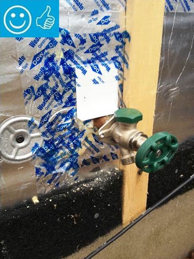
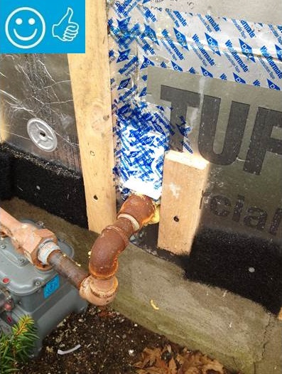
A wall water barrier blocks the penetration of moisture that gets past the siding and provides a path for it to safely drain down and away from the wall. The water-resistant surface could be house wrap that is lapped shingle style, water-resistant rigid foam insulation that is taped or sealed at all seams, or a wet-applied moisture-resistant coating. The water barrier must be carefully sealed and flashed at all exterior wall openings and penetrations (e.g., windows, doors, water spigots, exhaust vent outlets, HVAC condensate lines, light fixtures, and receptacles), and all wall intersections (e.g., roofs, foundations, and other transitions).
Questions? Comments? Contact our webmaster.