

Scope
Construct a double-wall consisting of two framed walls forming a wide wall cavity for more insulation in the home’s exterior walls.
- Install a continuous air control layer per the detailed drawings shown in the Description tab. Seal all seams, gaps, and holes. The location of the air control layer will be determined by the type of double-stud wall being installed.
- Install a vapor control layer per the detailed drawings shown in the Description tab. The location of the vapor control layer is determined by the type of double-stud wall being installed and the climate zone where the home is located.
- Install insulation without misalignments, compressions, gaps, or voids.
OR
- Completely fill the entire cavity of the double-stud wall assembly without misalignments, compressions, gaps, or voids.
- ENERGY STAR requires that insulation fill the entire wall cavity and that insulation cover the interior studs to an R value of at least ≥R-3 in IECC Climate Zones 1 to 4 or ≥R-5 in IECC Climate Zones 5 to 8 (ENERGY STAR).
See the Compliance Tab for links to related codes and standards and voluntary federal energy-efficiency program requirements.
Description
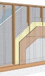
Double-stud wall construction is one option for high R-value walls. They are relatively inexpensive to construct and use readily available materials that construction crews may be more familiar with than other high-R-value options such as structural insulated panels (SIPS) and insulated concrete form (ICF) walls. Double-stud wall construction consists of two stud-framed walls set up next to each other to form an extra thick wall cavity that can be filled with insulation. Because the interior and exterior framing are separated by insulation, thermal bridging is also reduced or eliminated. Building Science Corporation, a Building America research partner, investigated several forms of double-stud wall construction including double-stud walls, truss walls, and offset frame walls in several research studies on high R-value walls.
- High-R Walls Case Study Analysis (Straube and Smegal 2009) - The analysis in this report includes a summary of historical wall construction types and R-values, current construction strategies, and wall types that will likely become popular in the future based on considerations such as energy and material availability.
- Moisture Management for High R-Value Walls (Lepage, Schumacher and Lukachko 2013) – This report explains moisture-related concerns for high R-value wall assemblies. Hygrothermal simulations were prepared for several common approaches to high R-value wall construction in six U.S. cities (Houston, Atlanta, Seattle, St. Louis, Chicago, and International Falls) representing a range of climate zones (2, 3, 4C, 4, 5A, and 7, respectively).
- Monitoring of Double Stud Wall Moisture Conditions in the Northeast (Ueno 2014) – This report explains moisture conditions in double-stud walls that were monitored in Zone 5A (Massachusetts); three double-stud assemblies were compared: 12" of ocSPF, 12" of cellulose, and 5-½" of ocSPF at the exterior of a double-stud wall (acting as a control wall).
BSC’s latest recommendations can be found at www.buildingscience.com. Some of the forms they investigated are described below.
Double-stud walls would be designed and specified by the architect and implemented by the framers. Site supervisors should ensure that framers and trades responsible for air sealing, insulating walls, and installing windows are knowledgeable or trained in techniques required for double-stud wall construction and that skill level expectations are included in the contracts for these trades.
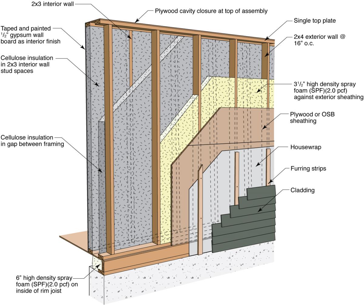
How to Construct a Double-Stud Wall with Interior Framing and Cellulose Insulation
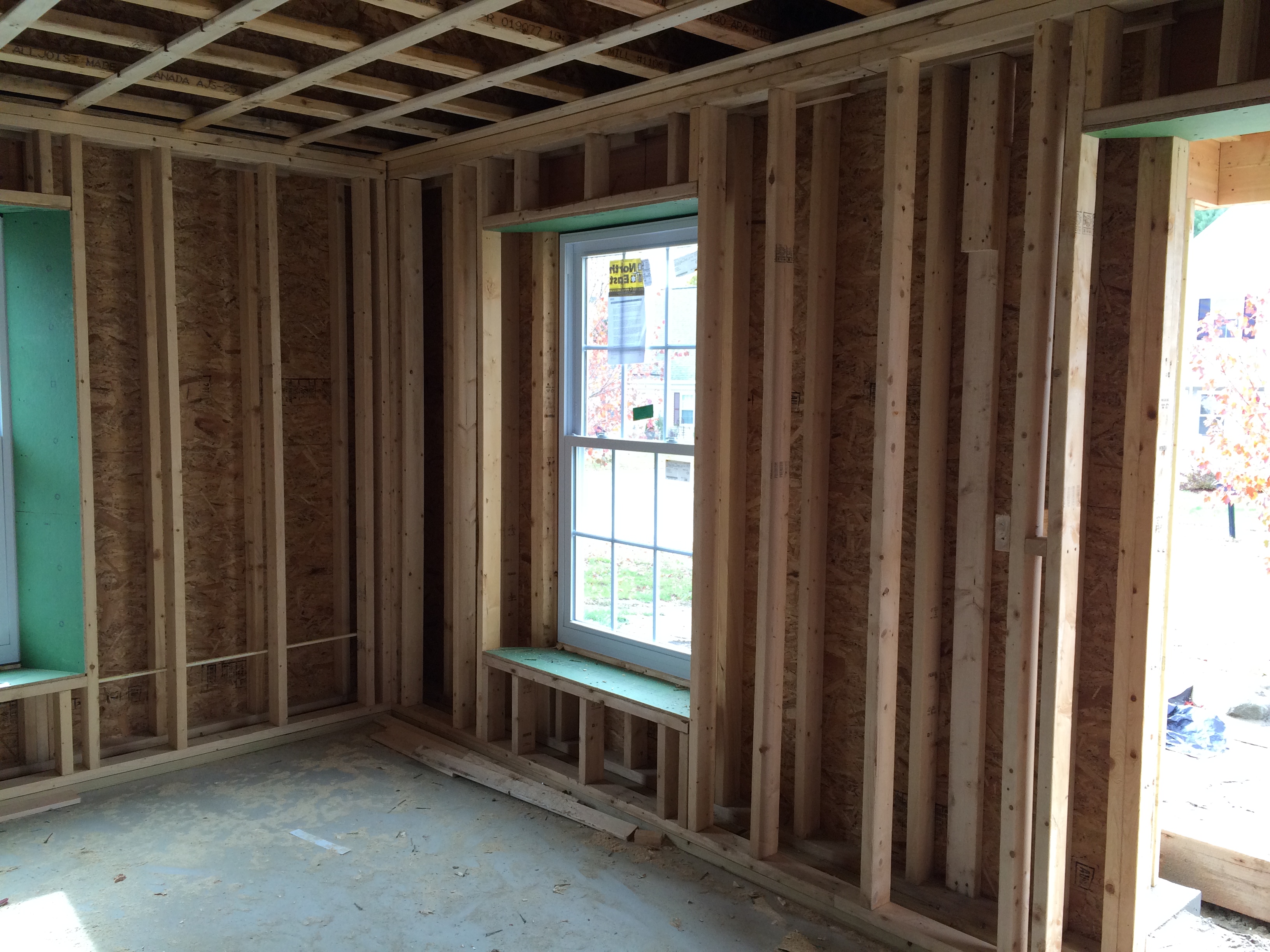
One form of double-stud wall construction consists of an exterior 2x6 or 2x4 stud-framed structural wall and a second 2x4 nonstructural wall built to the inside with a gap in between of several inches. If the studs in each wall are installed at the same spacing (e.g., 24-inch on-center) they can be staggered, although research has shown only minor improvement (<R-1) when staggering the studs (CARB 2009). Plywood boxes must be installed around the rough-in spaces for installing windows, which are typically installed flush with the exterior wall. The cladding attachment is the same as normal stud-framed construction practice.
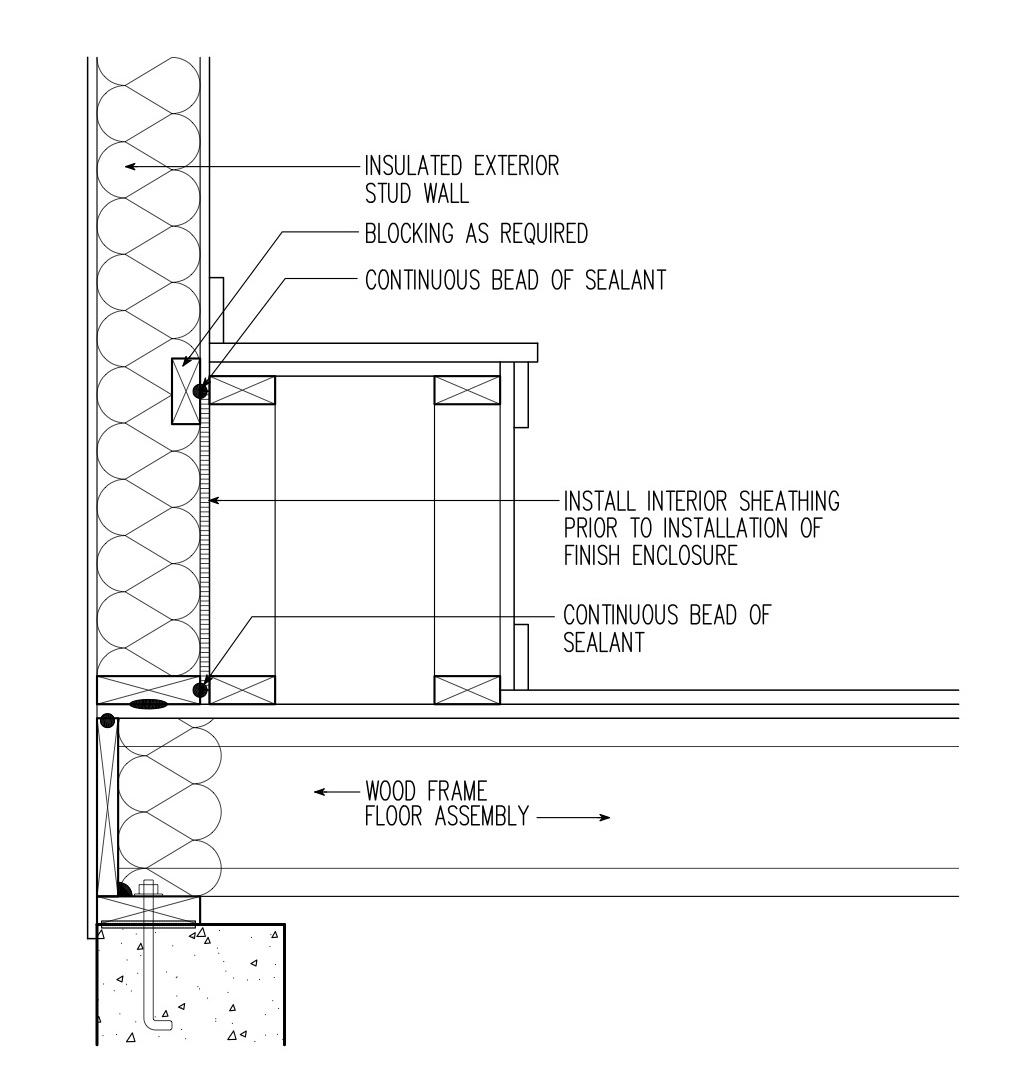
The example shown here uses a 2x4 exterior structural wall built at 16-inches on-center and a second minimum 2x3 wall that is nonstructural but is used to support drywall and electrical services. The two stud walls plus the gap in between provide a 9.5-inch cavity for cellulose insulation, which would have a clear-wall R-value (for that section of the wall without interruptions) of R-34 or a whole-wall R-value of R-30 (Straube and Smegal 2009). In this example, no vapor retarder is needed in warmer climate zones (1 through 4). A Class II vapor retarder is recommended in cold climate zones (5 and higher) (Ueno 2014). If one is installed, it should also be an air barrier/air control layer and it should be located on the exterior side of the interior wall. Care should be taken that insulation on both sides of this layer is fully aligned along the entire length of the wall.
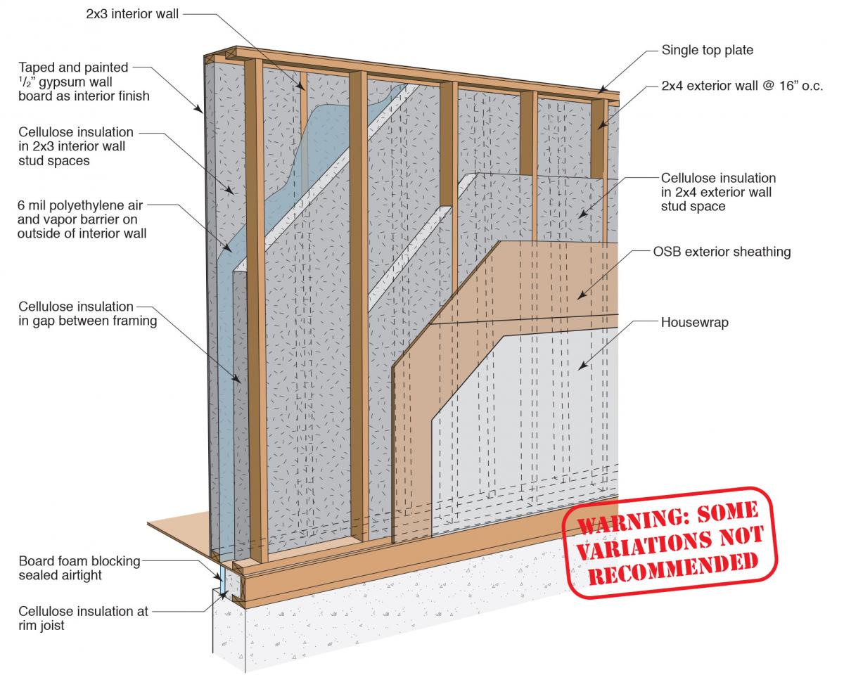
Note: A vapor retarder is not required/needed for warmer climate zones (1 through 4) but a Class II vapor retarder is recommended for cold climate zones (5 and higher). This vapor retarder should also be an air barrier/air control layer and be located on the exterior side of the interior wall (image courtesy of BSC, 2015)
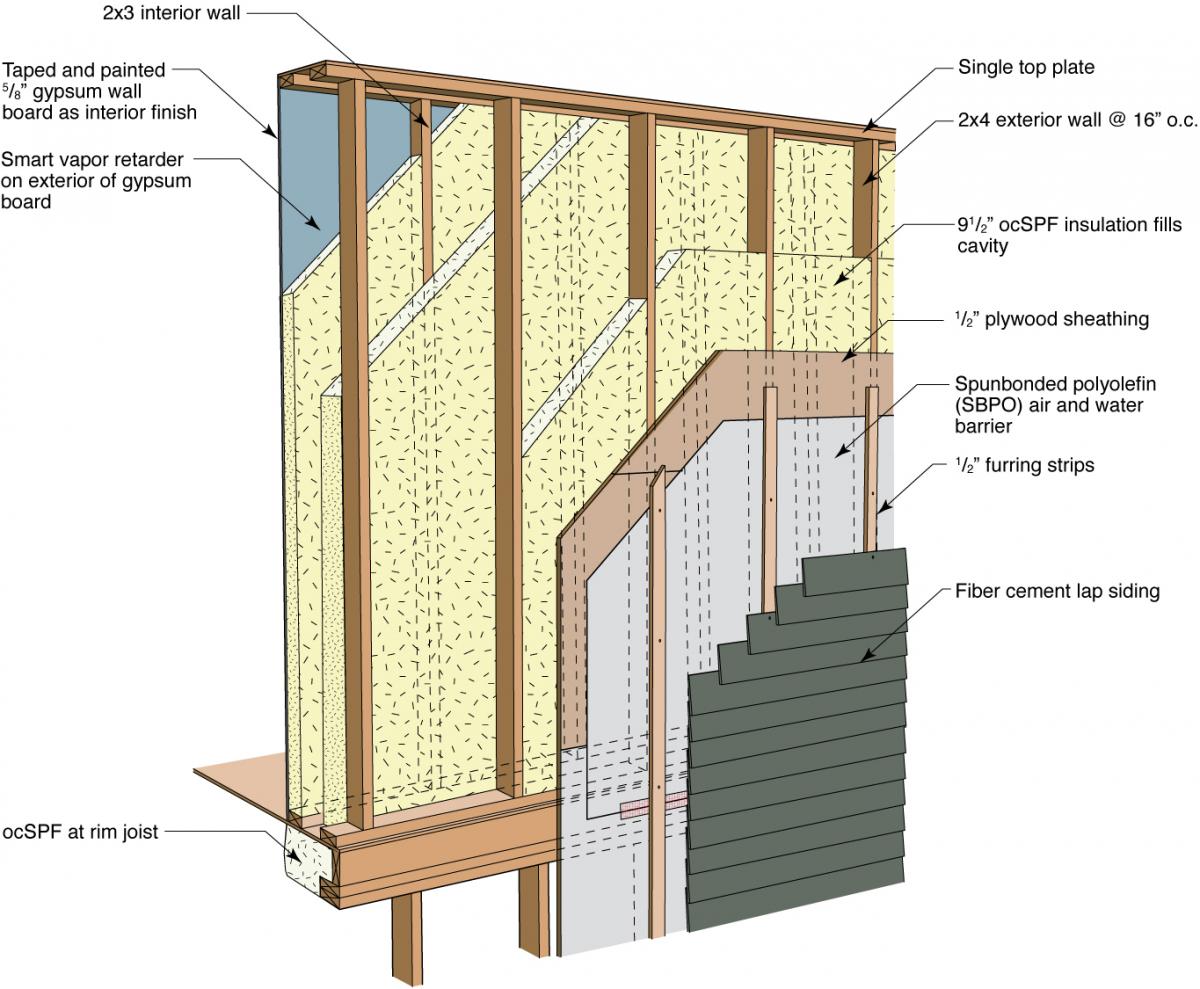
How to Construct a Double-Stud Wall with Outside Framing and Cellulose Insulation
Another form of double-stud wall construction consists of an interior 2x6 or 2x4 stud-framed structural wall and a second 2x4 non-structural exterior wall attached at each stud and cantilevered out. This frees up floor space compared to a traditional double-stud wall. The gap between the framing provides several inches for loose-fill or batt insulation (cellulose or fiberglass).
In this example, a 2x4, 16-inch on-center interior load-bearing wall is connected to a 2x4 exterior non-bearing wall to provide 9.5 inches of cavity width that is filled with cellulose insulation for a calculated whole-wall R-value of R-35. The air and vapor control layers are the plywood or OSB sheathing on the exterior of the interior wall. The permeance and location of vapor control is dependent on the climate zone (BSC 2008). In warmer climate zones (1 through 4) no vapor retarder is required/needed.
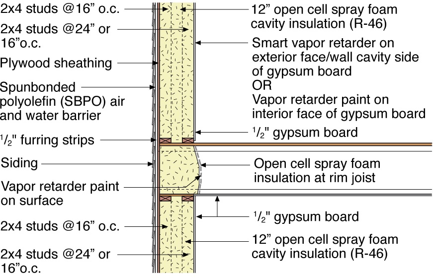
How to Construct a Double-Stud Wall with Open-Cell Spray Foam
A double-stud wall filled with open-cell spray foam (ocSPF) is an inexpensive way to decrease the air leakage susceptibility of double-stud walls commonly filled with cellulose insulation. The ocSPF acts to seal the OSB from any sources of air leaks between the exterior and interior stud walls (Lepage, Schumacher, and Lukachko 2013). In warmer climate zones (1 through 4), the ocSPF provides sufficient vapor resistance, provided that there is a ventilated cladding. In cold climate zones (5 and higher), a Class II vapor retarder (smart vapor retarder or vapor retarder paint) is needed (Ueno 2014). A Class I vapor retarder is not recommended in any of the climate zones.
In this example, a double wall is constructed consisting of a 2x4 exterior structural wall built at 16-inches on-center and an interior minimum 2x3 non-structural wall. The interior and exterior walls together form a 9.5-inch cavity that is filled with ocSPF for a calculated whole-wall R-value of R-37. In cold climate zones, additional levels of vapor control are required for this assembly; therefore, a smart vapor retarder is installed on the back of gypsum wall board. Alternatively, a vapor retarder paint can be used on the interior face of the gypsum board. No vapor control is needed in warmer climate zones.
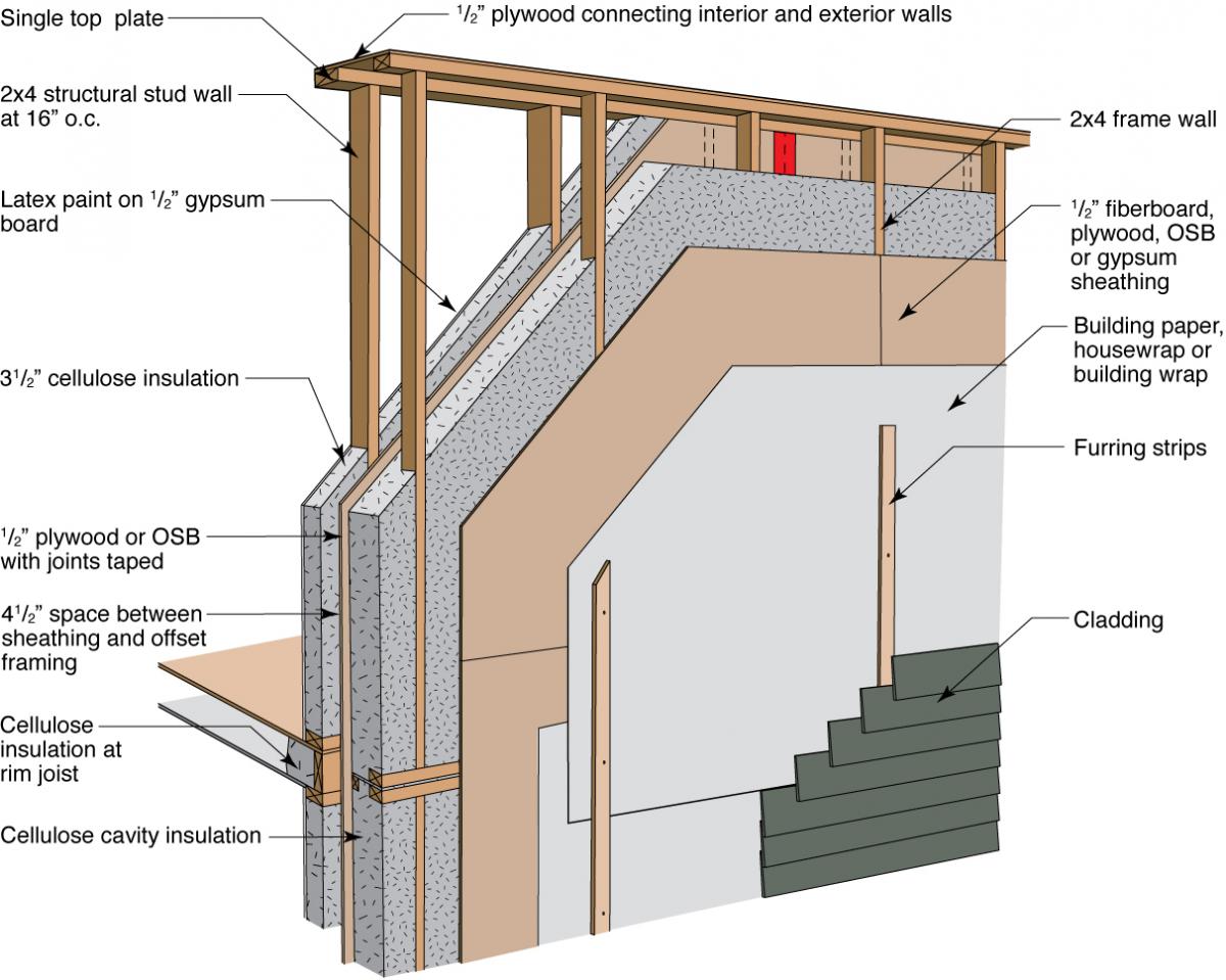
How to Construct a Double-Stud Wall with Closed-Cell Spray Foam and Cellulose Insulation
The standard double-stud wall concept can be improved through the use of closed-cell spray foam (ccSPF) installed directly against the exterior wall sheathing. The remainder of the framing cavity is filled with loose-fill fiber insulation such as cellulose or fiberglass. This is described as a hybrid insulation strategy (Lepage, Schumacher, and Lukachko 2013). In this example, high-density spray foam provides increased air sealing and moisture protection, decreasing the risk of wintertime condensation on the interior side of the exterior wall while less expensive cellulose provides additional R-value.
This example again uses a 2x4 exterior structural wall built at 16-inches on-center and an interior minimum 2x3 non-structural wall providing a 9.5-inch cavity. The exterior wall is covered with plywood or OSB sheathing, then the inside surface of the sheathing is covered with 3.5 inches of high-density spray foam. The remaining 6 inches of the cavity is filled with cellulose insulation, which provides a calculated whole-wall R-value for this assembly of R-40 (BSC 2008). The high-density spray foam insulation is the vapor control layer; therefore, no additional vapor control is required. The amount of high-density spray foam insulation needed to control condensation at the sheathing is dependent on the climate zone.
Note: The high-density spray foam insulation is the vapor control layer; therefore, no additional vapor control is required. The amount of high-density spray foam insulation to control condensation at the sheathing is dependent on the climate zone (image courtesy of BSC, 2015).
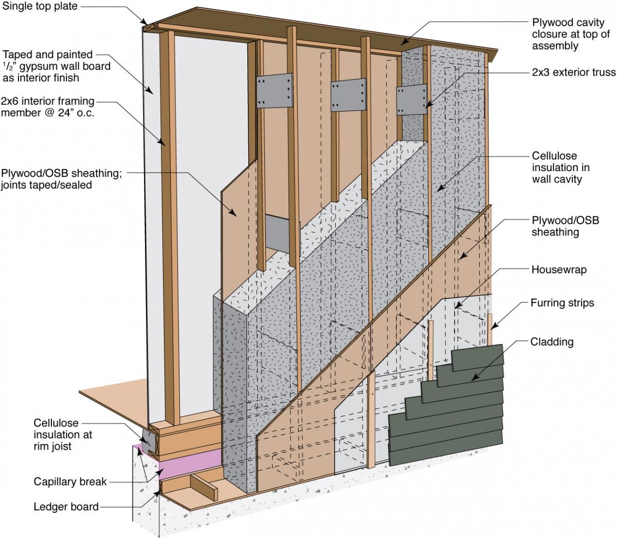
How to Construct a Truss Wall
The truss wall uses two sets of studs like the double-stud wall, but in this case the interior wall is the load-bearing wall. The interior wall can be constructed with 2x6 studs at 24 inches on-center or 2x4 studs at 16 inches on-center. The exterior wall is attached at each stud and hangs cantilevered outside of the foundation wall, which frees up floor space compared to a traditional double-stud wall. The interior and exterior wall studs are aligned and connected with plywood gusset plates toward the top, middle, and bottom of each pair of studs, and a plywood cavity closure at the top and bottom of the stud cavities. These gussets and closures provide stability so that the walls can be further apart, allowing more room for insulation. The bottom edge of the exterior wall drops below the sill plate, providing space that can be filled with insulation along the exterior side of the rim joist, thus minimizing the thermal bridging that can otherwise occur through the rim joist.
In this example a 2x6, 24-inch on-center interior structural wall is connected to a 2x3, 24-inch on-center exterior non-structural wall spaced to provide 12 inches of cavity width that is filled with cellulose insulation for a calculated whole-wall R value of R-36. The air and vapor control layers are the plywood or OSB sheathing on the exterior of the interior structural wall. A fully-adhered membrane on the outside of the OSB sheathing can be used. The permeance and location of vapor control is dependent on the climate zone (BSC 2008).
Ensuring Success
Install the air control layer in a continuous manner.
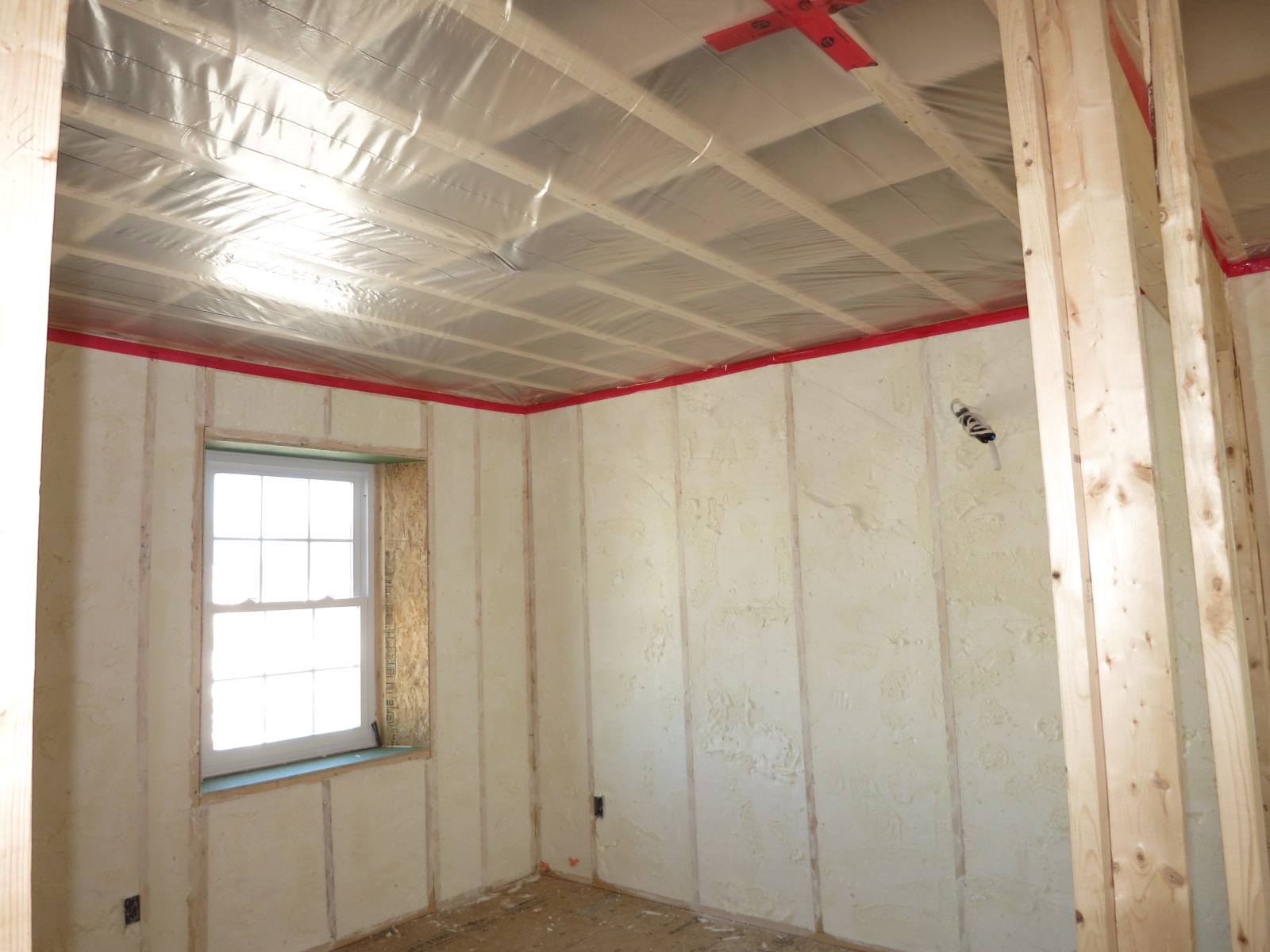
An infrared camera used in conjunction with blower door testing may help indicate the thoroughness of insulation coverage and may also help detect air leakage through the wall, if a sufficient temperature difference exists between the outside and the conditioned space of the house. Insulation installation should be inspected by the site supervisor before drywall is installed.
Region
The permeance and location of vapor control is dependent on the climate zone.
In warmer climate zones (1 through 4), no vapor barrier is required/needed.
The map in Figure 1 shows the climate zones for states that have adopted energy codes equivalent to the International Energy Conservation Code (IECC) 2009, 12, 15, and 18. The map in Figure 2 shows the climate zones for states that have adopted energy codes equivalent to the IECC 2021. Climate zone-specific requirements specified in the IECC are shown in the Compliance Tab of this guide.

Source
2012 edition of code establishing a baseline for energy efficiency by setting performance standards for the building envelope (defined as the boundary that separates heated/cooled air from unconditioned, outside air), mechanical systems, lighting systems and service water heating systems in homes and commercial businesses.

Source
2021 edition of code establishing a baseline for energy efficiency by setting performance standards for the building envelope (defined as the boundary that separates heated/cooled air from unconditioned, outside air), mechanical systems, lighting systems and service water heating systems in homes and commercial businesses.
Training
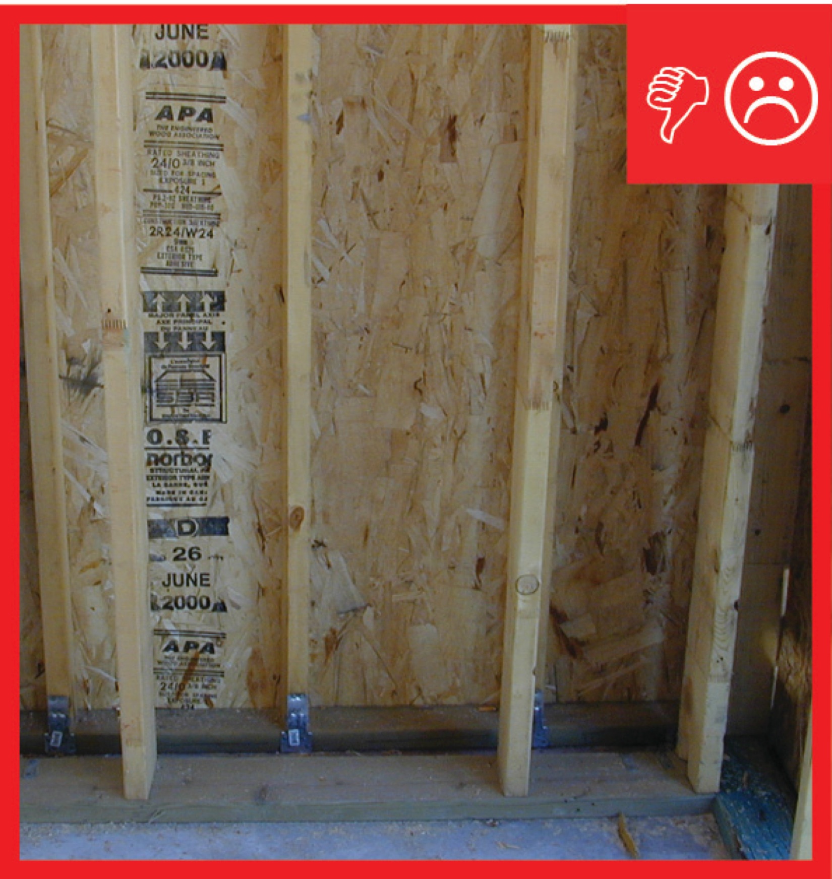
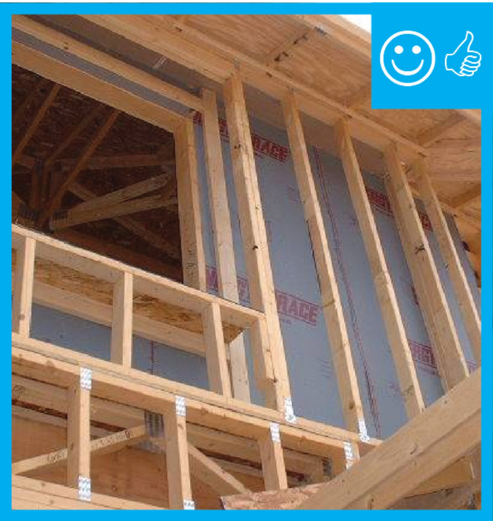
Right and Wrong Images
Source

Source
Source
Source
Guide describing details that serve as a visual reference for each of the line items in the Thermal Enclosure System Rater Checklist.
Source
Guide describing details that serve as a visual reference for each of the line items in the Thermal Enclosure System Rater Checklist.
Source

Source
Source

Source
Videos

CAD Files
More Info
References and Resources
*For non-dated media, such as websites, the date listed is the date accessed.
Contributors to this Guide
The following authors and organizations contributed to the content in this Guide.
Building Science Corporation, lead for the Building Science Consortium (BSC), a DOE Building America Research Team
Steven Winter Associates, lead for the Consortium for Advanced Residential Buildings (CARB), a DOE Building America Research Team
Sales
Double-Wall Framing = Double-Wall Thermal Blanket
Technical Description
One way to achieve very high levels of insulation in walls is to build two stud walls separated by an air space. The inner wall provides framing for attaching gypsum board; the outer wall does the same for sheathing, a weather barrier, and siding. Two 2x4 framed walls spaced three inches apart will provide a wall cavity about 10 inches deep. This spacing eliminates thermal bridging. When fully insulated, this double-wall thermal blanket creates a quiet, efficient, and comfortable home.
Questions? Comments? Contact our webmaster.