
Blown Insulation for Cavities of Existing Exterior Walls

    Scope
    Scope Images
    Image
    Siding has been removed so cellulose insulation can be dense-packed into the exterior walls of this home
    Scope

    Upgrade existing exterior walls that are uninsulated or poorly insulated by adding blown-in insulation in the wall cavities.

    • Determine if the insulation is to be installed from inside or outside the home.
    • Access the existing walls to determine the location of existing framing and blocking.
    • Drill or cut holes for insulation installation.
    • Completely fill wall cavities with blown insulation to the manufacturer’s recommended density for “dense” installation.
    • Verify that all of the wall cavities are filled.
    • Patch walls. If installation was done from the exterior, repair or install a proper drainage plane and air barrier.

    For more information on conditions that may be encountered when working with walls in existing homes, see the Pre-Retrofit Assessment of  Walls, Windows, and Doors.

    The U.S. Department of Energy’s Standard Work Specifications has additional information on dense packing blown insulation.

    See the Compliance Tab for related codes and standards, and criteria to meet national programs such as DOE’s Zero Energy Ready Home programENERGY STAR Single-Family New Homes, and Indoor airPLUS.

    Description
    Description

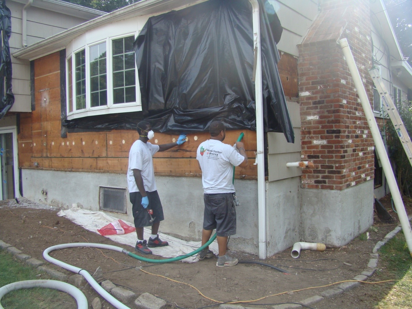
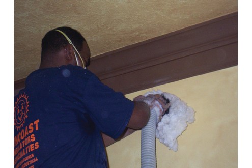
    When considering methods for insulating exterior walls in an existing home, one common and somewhat uninvasive method is known as drill and fill. In this method, small holes are made in the interior or exterior wall near the top of the wall at each wall cavity, then the wall cavities are filled with blown-in insulation. See Figure 1 and 2.) An ideal time to do an exterior installation is when a house is being re-sided. Re-siding offers the opportunity to check and install or re-install a drainage plane like house wrap if necessary. Re-siding also offers the opportunity to install exterior rigid foam insulation, in addition to or instead of cavity insulation. (See Rigid Foam Insulation for Existing Exterior Walls).

    The siding has been removed so cellulose insulation can be dense-packed into the exterior walls of this home.
    Figure 1. The siding has been removed so cellulose insulation can be dense-packed into the exterior walls of this home (Source: Courtesy of CARBSteven Winter Associates). 


    Fiberglass insulation is dense packed into a wall cavity from the interior side of the exterior wall.
    Figure 2. Fiberglass insulation is dense packed into a wall cavity from the interior side of the exterior wall (Source: Courtesy of CARBSteven Winter Associates).


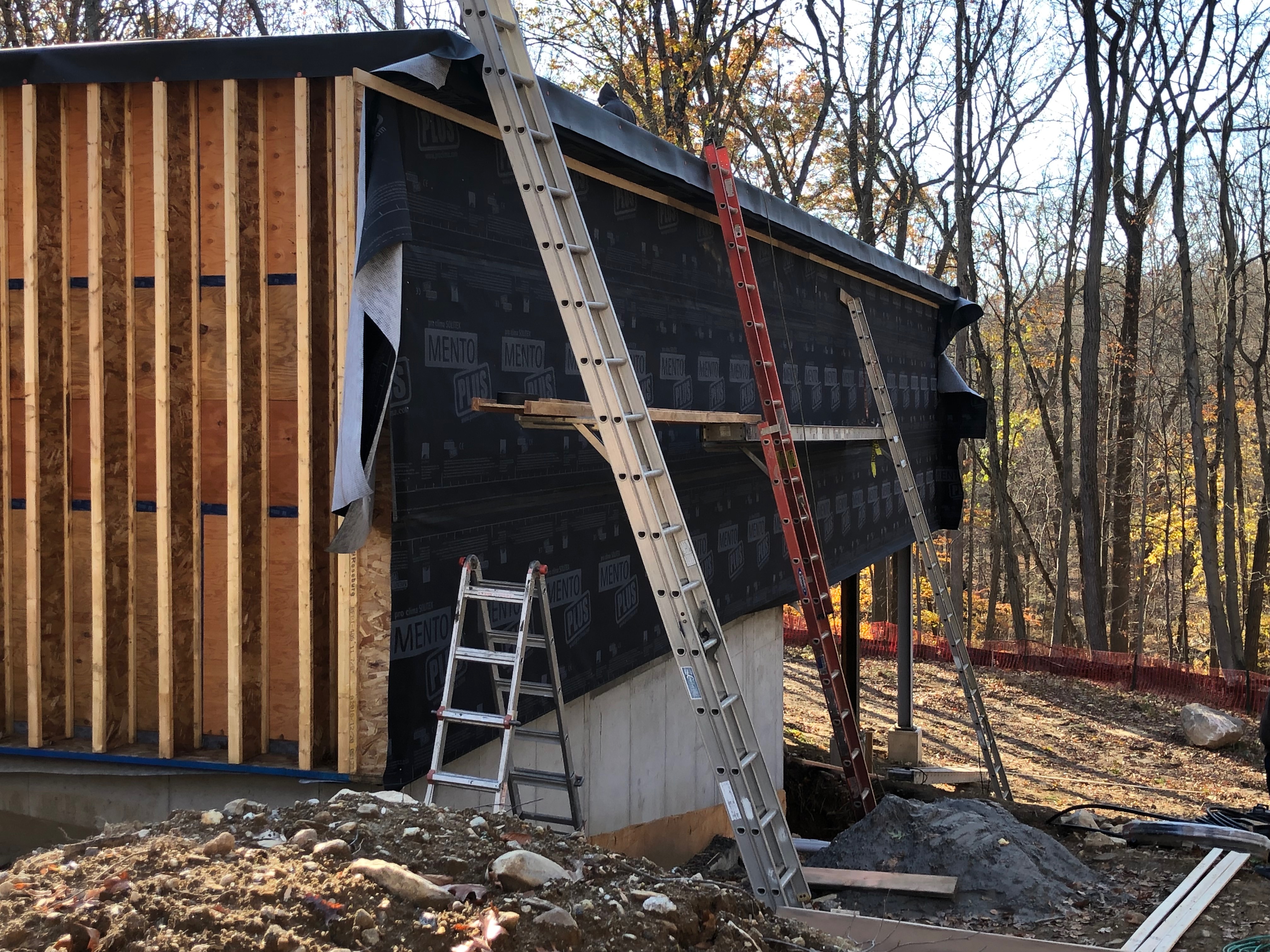
    If the blown-in insulation is to be installed from the exterior as part of a siding replacement, an ideal opportunity is presented to improve the airtightness of the wall assembly with minimal effort. Exposed structural panels (plywood or OSB) can be effectively air sealed with fluid-applied air barriers, low-expansion foam, caulk, or quality tapes. Board sheathing should be covered by a house wrap, with all laps sealed with appropriate tape. Continuous rigid foam sheathing can be applied over existing sheathing to provide additional R-value, air sealing, and a continuous drainage plane.

    It is critical for water management and durability that the wall assembly’s drainage plane be maintained. When blown-in insulation is added from the exterior, the drainage plane (if existing) will be breeched and it must be made whole by appropriate patching or full replacement. The chosen method will depend on the amount of access and the state of the existing drainage plane material. If the insulation is to be installed from the interior, the drainage plane will not be affected.

    Depending on the level of disturbance to existing exterior walls (interior and exterior sides), be aware of lead safety rules for homes built prior to 1980. In addition, if a home has knob and tub wiring, the National Electrical Code (NEC) Article 394.1 scope does not allow insulation to be applied to or surround the wiring.

    This guide primarily focuses on wood framing construction with exterior wood sheathing and interior gypsum wall board. For more information on drill and fill installation in wood-framed walls as well as in other exterior wall materials, see the Drill & Fill Installation Guide.

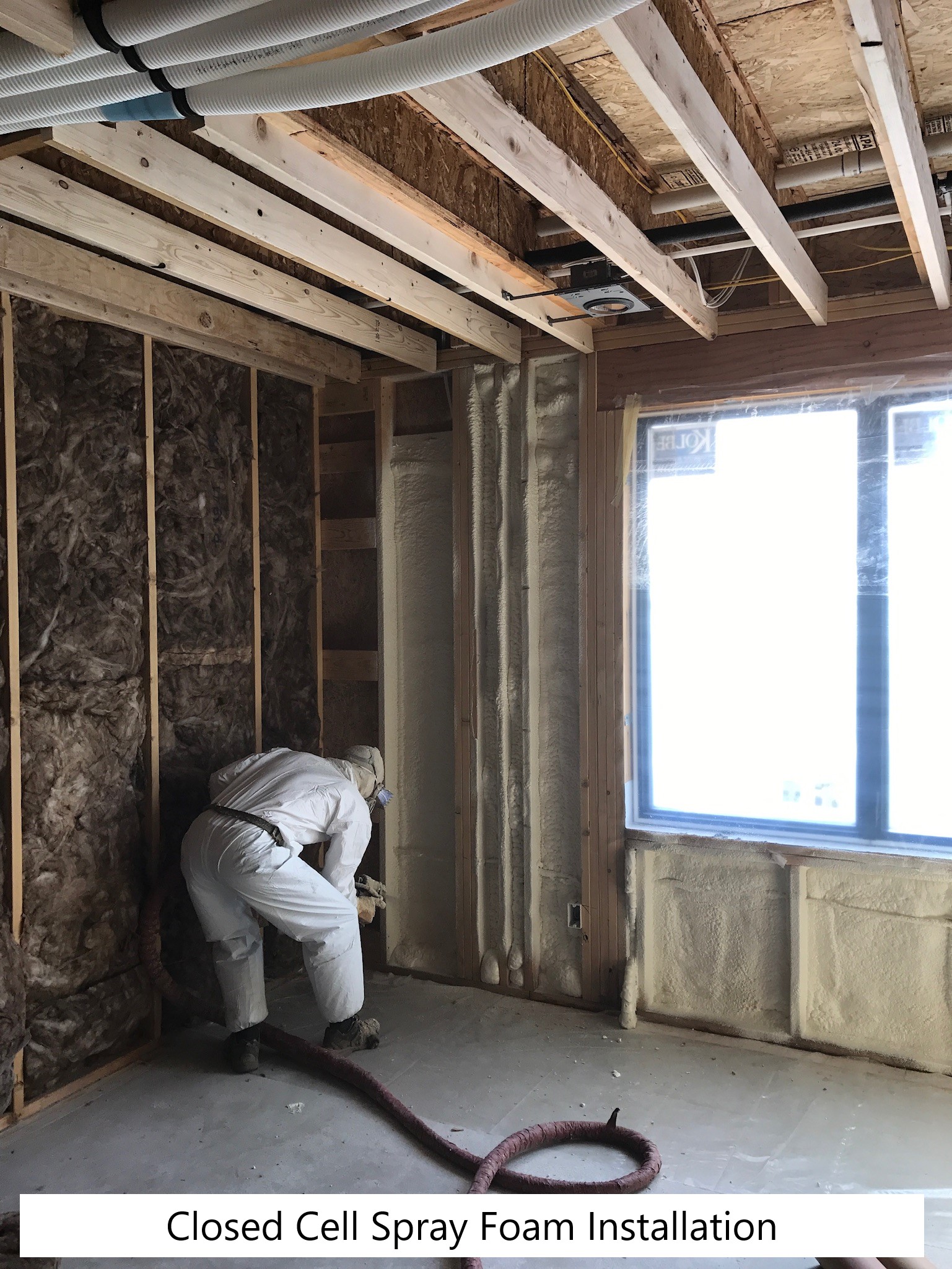
    For other approaches to insulating exterior walls in existing homes, see the guides Spray Foam Insulation for Cavities of Existing Exterior Walls and Rigid Foam Insulation for Existing Exterior Walls.

    How to Blow In Insulation into Existing Exterior Walls

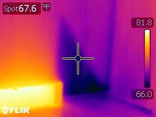
    1. Determine if the existing exterior wall cavities are insulated. Options for assessing insulation levels include making a small cut-out in the interior gypsum wall board, viewing cavity insulation from the side of an electrical junction box cutout (shut off power to electrical outlets to avoid potential safety hazards), or using an infrared thermal imaging camera to qualitatively assess insulation levels.
      1. If the wall cavities are empty proceed to step 2.
      2. If the wall cavities have some existing insulation:
        1. Existing blown insulation that has deteriorated can remain (or be vacuumed out) and additional blown insulation can be installed in the wall cavity to the desired fill and density.
        2. Existing batt insulation that has deteriorated can block blown insulation, preventing it from completely filling the cavity. Cut out a 1-foot strip along the wall near the floor on either the interior or exterior side of the wall, then pull out the old batt insulation to allow proper installation of the blown insulation into the wall cavities. Alternatively, use an infrared camera to verify that the blown insulation has adequately filled the wall cavities around the existing batt insulation.
    2. Decide if insulation is to be blown from the interior or from the exterior.
    3. Verify that the exterior wall framing is not balloon framing. If the walls are balloon framed, blocking will need to be installed at the top and bottom of the walls to provide a barrier between the wall cavities and the basement below and attic above to allow for dense packing of the cavities.
    4. Identify the wall studs and use painter’s masking tape to mark them.
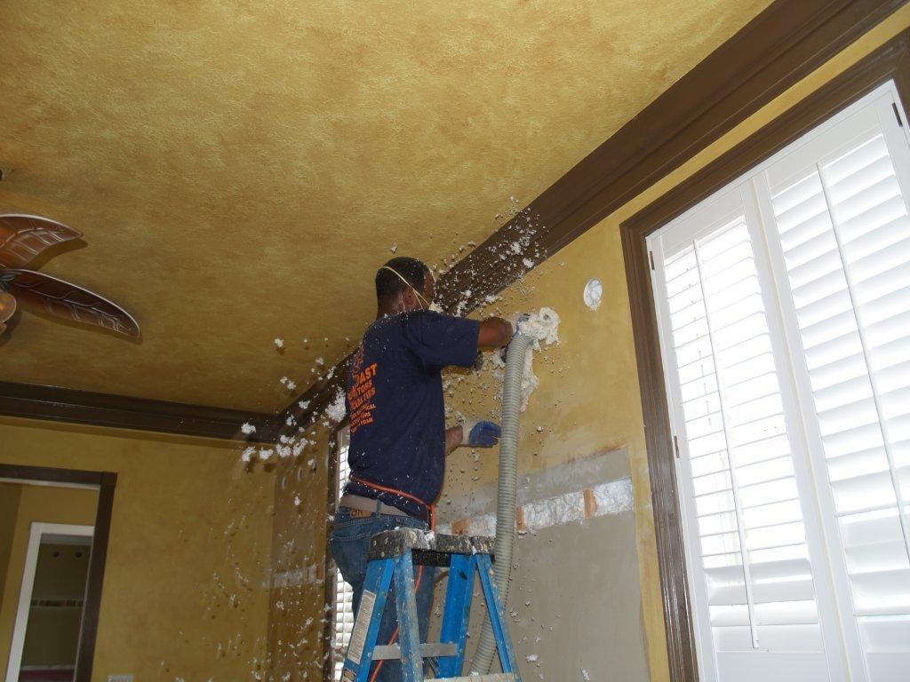
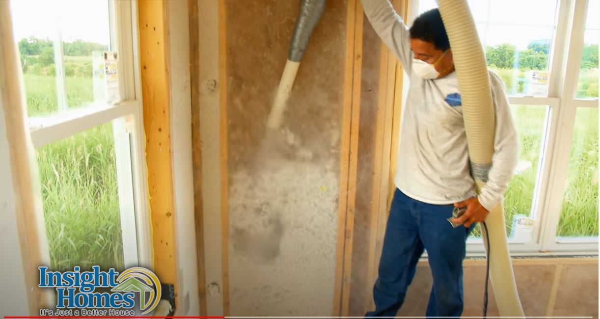
    5. Using a hole saw, drill 1-inch or 2-inch holes (depending on the size of the blower nozzle) in the center of each stud cavity, roughly 6 inches below the ceiling (see Figure 3). It may be necessary to also drill a lower hole to ensure the full cavity is packed with insulation. If there is blocking or other obstacles in the wall cavity (identified using infrared camera), make an additional hole below the blocking (see Figures 4 and 5). Remember to drill in to any cavities above door headers and above and below windows, as well as wall cavities behind cabinets on exterior walls. Also if a bathroom is on an exterior wall, bathroom tiles may need to be “popped” off prior to drilling a hole through the wall board.
    6. Blow in new insulation to the desired density. Confirm manufacturer’s lbs/ft3 recommendations to achieve “dense” packing. The common insulation type is a dense-packed blown cellulose or fiberglass insulation. For information on blowing machines and nozzles, see the Drill & Fill Installation Guide.
    7. Fill all exterior wall cavities then re-verify with an infrared camera to ensure that all cavities are completely filled before patching.
    8. Once verified, patch the holes. For interior penetrations, patch the holes with gypsum board or rigid foam plugs and joint compound. When dry, sand smooth then paint. For exterior penetrations, patch requirements will differ depending on whether siding was removed or remained in place. Repair the drainage plane and air barrier as needed before installing siding.
    Fiberglass insulation is dense-packed into exterior walls through holes cut into the interior side of the exterior walls a few inches from the ceiling.
    Figure 3. Fiberglass insulation is dense-packed into exterior walls through holes cut into the interior side of the exterior walls a few inches from the ceiling. An inspection band was cut out of the gypsum wall board to verify installation for this demonstration project (Source: Courtesy of CARBSteven Winter Associates).


    Infrared image shows that insulation is missing above the window header and that cross bracing in an exterior wall has blocked blown-in insulation from the upper corner of a wall cavity.
    Figure 4. Infrared image shows that insulation is missing above the window header and that cross bracing in an exterior wall has blocked blown-in insulation from the upper corner of a wall cavity (Source: Courtesy of NREL). 
    Infrared image shows cross bracing in an exterior wall has blocked blown-in insulation, resulting in a void in the wall cavity.
    Figure 5. Infrared image shows cross bracing in an exterior wall has blocked blown-in insulation, resulting in a void in the wall cavity (Source: Courtesy of NREL).


    Success
    Ensuring Success

    Infrared imaging is a recommended tool to help identify framing and blocking in existing walls and to determine the thoroughness of insulation coverage. Voids will be most visible when there is a significant temperature difference between the outside and the conditioned space of the house.

    Climate
    Climate

    The exterior wall assembly should be designed for a specific hygrothermal region, rain exposure zone, and interior climate.  The climate zones are shown on the map below, which is taken from Figure C301.1 of the 2012 IECC.

    The map in Figure 1 shows the climate zones for states that have adopted energy codes equivalent to the International Energy Conservation Code (IECC) 2009, 12, 15, and 18. The map in Figure 2 shows the climate zones for states that have adopted energy codes equivalent to the IECC 2021. Climate zone-specific requirements specified in the IECC are shown in the Compliance Tab of this guide. 

    Climate Zone Map from IECC 2009, 12, 15, and 18.

    Figure 1. Climate Zone Map from IECC 2009, 12, 15, and 18 (Source: 2012 IECC).


    Climate Zone Map from IECC 2021.

    Figure 2. Climate Zone Map from IECC 2021 (Source: 2021 IECC).


    The appropriate vapor permeance and location of vapor control is dependent on the climate zone and the overall configuration of the insulated wall assembly. There are many factors to consider when installing blown-in insulation from either the interior or exterior. Understanding Vapor Barriers is a good primer on what needs to be considered regarding vapor retarders.

    The insulation levels should be based on the minimum requirements for vapor control in the current adopted building code and the minimum requirements for thermal control in the current energy code.  Additional insulation can be added above these minimums to create high R-Value exterior wall assemblies. The table below provides the minimum thermal resistance (R-value) requirements for exterior walls specified in the 2009 IECC (ICC 2009b) and the 2012 IECC (ICC 2012b), based on climate zone.

    Wall Insulation Requirements per the 2009 and 2012 IECC.

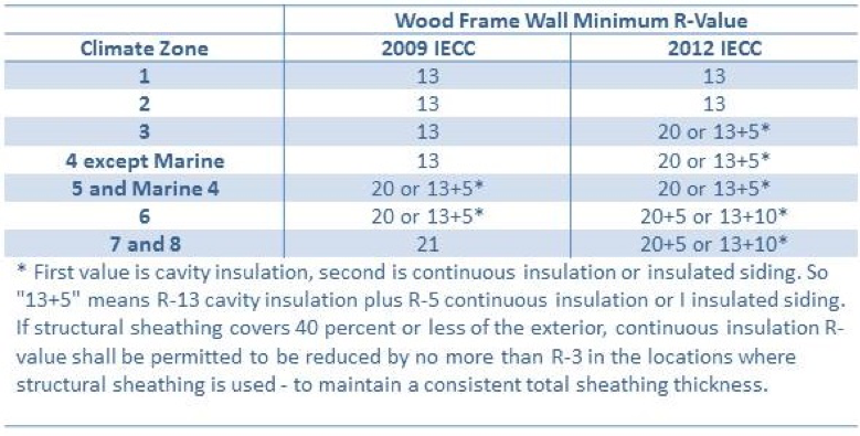
    Table 1. Wall Insulation Requirements per the 2009 and 2012 IECC.


    Training
    Right and Wrong Images
    Image
    Right – Closed-cell spray foam seals the wall cavities.
    Right – Closed-cell spray foam seals the wall cavities.
    Image
    Larsen trusses made of 9-inch I joists, set perpendicular to the exterior wall at 16 inches on center, provide a second wall cavity that can be filled with blown insulation, greatly increasing the insulation value in the walls.
    Larsen trusses made of 9-inch I joists, set perpendicular to the exterior wall at 16 inches on center, provide a second wall cavity that can be filled with blown insulation, greatly increasing the insulation value in the walls.
    Image
    The Larsen-truss 9-inch wall cavities were covered with a smart vapor membrane that was fastened to the trusses with furring strips, which also provide an air gap behind the wood siding; each truss cavity is then filled with blown cellulose.
    The Larsen-truss 9-inch wall cavities were covered with a smart vapor membrane that was fastened to the trusses with furring strips, which also provide an air gap behind the wood siding; each truss cavity is then filled with blown cellulose.
    Image
    Right – Fiberglass insulation is blown in to fill wall cavities.
    Right – Fiberglass insulation is blown in to fill wall cavities.
    Videos
    Publication Date
    Author(s)
    Home Innovation Research Labs
    Organization(s)
    Home Innovation Research Labs
    Description
    Video from Home Innovation Research Labs giving a background on installing blown cellulose insulation in stud cavities.
    Compliance

    Compliance

    The Compliance tab contains both program and code information. Code language is excerpted and summarized below. For exact code language, refer to the applicable code, which may require purchase from the publisher. While we continually update our database, links may have changed since posting. Please contact our webmaster if you find broken links.


    ENERGY STAR Single-Family New Homes, Version 3/3.1 (Rev. 11)

    National Rater Field Checklist

    Thermal Enclosure System.
    2. Fully-Aligned Air Barriers.7 At each insulated location below, a complete air barrier is provided that is fully aligned as follows:
    Walls: At exterior vertical surface of wall insulation in all climate zones; also at interior vertical surface of wall insulation in Climate Zones 4-8.9
    2.2 Walls behind showers, tubs, staircases, and fireplaces.

    Footnote 7) For purposes of this Checklist, an air barrier is defined as any durable solid material that blocks air flow between conditioned space and unconditioned space, including necessary sealing to block excessive air flow at edges and seams and adequate support to resist positive and negative pressures without displacement or damage. EPA recommends, but does not require, rigid air barriers. Open-cell or closed-cell foam shall have a finished thickness ≥ 5.5 in. or 1.5 in., respectively, to qualify as an air barrier unless the manufacturer indicates otherwise. If flexible air barriers such as house wrap are used, they shall be fully sealed at all seams and edges and supported using fasteners with caps or heads ≥ 1 in. diameter unless otherwise indicated by the manufacturer. Flexible air barriers shall not be made of kraft paper, paper-based products, or other materials that are easily torn. If polyethylene is used, its thickness shall be ≥ 6 mil.

    Footnote 9) All insulated vertical surfaces are considered walls (e.g., above and below grade exterior walls, knee walls) and must meet the air barrier requirements for walls. The following exceptions apply: air barriers recommended, but not required, in adiabatic walls in multifamily dwellings; and, in Climate Zones 4 through 8, an air barrier at the interior vertical surface of insulation is recommended but not required in basement walls or crawlspace walls. For the purpose of these exceptions, a basement or crawlspace is a space for which ≥ 40% of the total gross wall area is below-grade.

    Please see the ENERGY STAR Single-Family New Homes Implementation Timeline for the program version and revision currently applicable in your state.


    DOE Zero Energy Ready Home (Revision 07)

    Exhibit 1 Mandatory Requirements.
    Exhibit 1, Item 1) Certified under the ENERGY STAR Qualified Homes Program or the ENERGY STAR Multifamily New Construction Program. 
    Exhibit 1, Item 2) Ceiling, wall, floor, and slab insulation shall meet or exceed 2015 IECC levels and achieve Grade 1 installation, per RESNET standards. See the guide 2015 IECC Code Level Insulation – DOE Zero Energy Ready Home Requirements for more details.

    Exhibit 2 DOE Zero Energy Ready Home Target Home.
    The U.S. Department of Energy’s Zero Energy Ready Home program allows builders to choose a prescriptive or performance path. The DOE Zero Energy Ready Home prescriptive path requires builders to meet or exceed the minimum HVAC efficiencies listed in Exhibit 2 of the National Program Requirements (Rev 07), as shown below. The DOE Zero Energy Ready Home performance path allows builders to select a custom combination of measures for each home that is equivalent in performance to the minimum HERS index of a modeled target home that meets the requirements of Exhibit 2 as well as the mandatory requirements of Zero Energy Ready Home Exhibit 1.

    Exhibit 2, Insulation and Infiltration) Whole house leakage must be tested and meet the following infiltration limits:

    • Zones 1-2: ≤ 3 ACH50;
    • Zones 3-4: ≤ 2.5 ACH50;
    • Zones 5-7: ≤ 2 ACH50;
    • Zone 8: ≤ 1.5 ACH50;
    • Attached dwellings: ≤ 3 ACH50.

    Footnote 12) Building envelope assemblies, including exterior walls and unvented attic assemblies (where used), shall comply with the relevant vapor retarder provisions of the 2015 International Residential Code (IRC).
    Footnote 23) Envelope leakage shall be determined by an approved verifier using a RESNET-approved testing protocol.


    2009-2021 IECC and IRC Insulation Requirements Table

    The minimum insulation requirements for ceilings, walls, floors, and foundations in new homes, as listed in the 2009, 2012, 2015, 2018, and 2021 IECC and IRC, can be found in this table


    2009 International Energy Conservation Code (IECC)

    Table 402.4.2 Air Barrier and Insulation Inspection Component Criteria, Air barrier and thermal barrier: Exterior wall insulation is installed in substantial contact and continuous alignment with the air barrier. Air permeable insulation is not used as a sealing material.

    2012 IECC

    Exterior insulation for framed walls is in substantial contact and continuous alignment with the air barrier. Table R402.4.1.1 Air Barrier and Insulation Installation, Air barrier and thermal barrier: A continuous air barrier is installed in the building envelope including rim joists and exposed edges of insulation. Breaks or joints in the air barrier are sealed. Air permeable insulation is not used as a sealing material.

    20152018, and 2021 IECC

    Table R402.1.2 Insulation and Fenestration Requirements – meet or exceed the insulation levels listed in this table.

    Table R402.4.1.1 Air Barrier and Insulation Installation. Walls: Insulation in exterior framed walls is in substantial contact and continuous alignment with the air barrier. General requirements: A continuous air barrier is installed in the building envelope; breaks and joints in the air barrier are sealed. Air-permeable insulation is not used as an air-sealing material.

    Section R402.4.1.2 Testing. The building should be tested for air leakage in accordance with ASTM E 779 or E 1827 (or RESNET/ICC 380 in 2018 and 2021 IECC) and should have an air leakage rate of ≤ 5 in CZ 1 and 2 or ≤ 3 in CZ 3-8.

    Retrofit:  2009, 2012, 2015, 2018,  and 2021 IECC

    Section R101.4.3 (in 2009 and 2012). Additions, alterations, renovations, or repairs shall conform to the provisions of this code, without requiring the unaltered portions of the existing building to comply with this code. (See code for additional requirements and exceptions.)

    Chapter 5 (in 2015, 2018, 2020). The provisions of this chapter shall control the alteration, repair, addition, and change of occupancy of existing buildings and structures.


    2009 International Residential Code (IRC)

    Table N1102.4.2 Air Barrier and Insulation Inspection Component Criteria, Air barrier and thermal barrier: Exterior wall insulation is installed in substantial contact and continuous alignment with the air barrier. Air permeable insulation is not used as a sealing material.

    2012 IRC

    Exterior insulation for framed walls is in substantial contact and continuous alignment with the air barrier. Table N1102.4.1.1 Air Barrier and Insulation Installation, Air barrier and thermal barrier: A continuous air barrier is installed in the building envelope including rim joists and exposed edges of insulation. Breaks or joints in the air barrier are sealed.  Air permeable insulation is not used as a sealing material.

    20152018, and 2021 IRC

    N1102.4.1.1 Air Barrier and Insulation Installation. Walls: Insulation in exterior framed walls is in substantial contact and continuous alignment with the air barrier. General requirements: A continuous air barrier is installed in the building envelope; breaks and joints in the air barrier are sealed. Air-permeable insulation is not used as an air-sealing material.

    Retrofit:  2009, 2012, 2015, 2018,  and 2021 IRC

    Section R102.7.1 Additions, alterations, or repairs. Additions, alterations, renovations, or repairs shall conform to the provisions of this code, without requiring the unaltered portions of the existing building to comply with the requirements of this code, unless otherwise stated. (See code for additional requirements and exceptions.)

    Appendix J regulates the repair, renovation, alteration, and reconstruction of existing buildings and is intended to encourage their continued safe use.


    American Society for Testing Materials (ASTM) E1677-11

    Standard Specification for Air Barrier (AB) Material or System for Low-Rise Framed Building Walls. This specification covers minimum performances and specification criteria for an air barrier material or system for framed, opaque walls of low-rise buildings. The provisions are intended to allow the user to design the wall performance criteria and increase air barrier specifications for a particular climate location, function, or design.


    National Electrical Code (NEC)

    Article 394.1: If a home has knob and tub wiring, insulation should not be applied to touch or surround the wiring. 

    More

    More Info.

    Access to some references may require purchase from the publisher. While we continually update our database, links may have changed since posting. Please contact our webmaster if you find broken links.

    Case Studies
    References and Resources*
    Author(s)
    Puttagunta Srikanth,
    Vijayakumar Gayathri,
    Shapiro Carl,
    Zoeller William
    Organization(s)
    CARB,
    Steven Winter Associates,
    SWA
    Publication Date
    Description
    Report about a deep energy retrofit Cool Energy House.
    Author(s)
    National Renewable Energy Laboratory
    Organization(s)
    NREL
    Publication Date
    Description
    The Standard Work Specifications (SWS) are a tool for industry guidance to ensure effective, durable, and safe work is performed during home upgrades.
    Author(s)
    Johns Manville
    Organization(s)
    Johns Manville
    Publication Date
    Description
    The purpose for this document is to provide basic guidance on the use of proven installation techniques that can be used by installers to help ensure correct “dense pack” application of JM Spider® in drill & fill applications.
    Author(s)
    Wisconsin Focus on Energy
    Organization(s)
    Wisconsin Focus on Energy
    Publication Date
    Description
    High-density sidewall cavity insulation can be a major comfort and savings boost. It saves energy by slowing both conductive and convective losses, but only if the right things are done and done right. This always requires site-specific thinking.
    *For non-dated media, such as websites, the date listed is the date accessed.
    Contributors to this Guide

    The following authors and organizations contributed to the content in this Guide.

    Steven Winter Associates, lead for the Consortium for Advanced Residential Buildings (CARB), a DOE Building America Research Team

    Sales
    Building Science Measures
    Building Science-to-Sales Translator

    Deep Energy Retrofit = Ultra-Efficient Deep Energy Retrofit

    Image(s)
    Technical Description

    An ultra-efficient retrofit is a home renovation or upgrade that results in an energy-efficiency level at least 50% better than the home's, or similar home’s, historic energy consumption.

    Ultra-Efficient Deep Energy Retrofit
    Sales Message

    Ultra-efficient deep energy retrofits are homes that optimize energy efficiency improvements that also improve comfort, health, safety, and durability. What this means to you is a better living experience along with extremely low utility bills. Wouldn’t you agree this is a great opportunity to upgrade existing homes?

    Last Updated

    Did you find this information helpful?

    If you have questions and/or would like a reply to this feedback, please include your e-mail address in the message.
    This question is for testing whether or not you are a human visitor and to prevent automated spam submissions.