
Air Seal HVAC Cabinet Seams

    Scope
    Scope Images
    Image
    Seal all holes and seams in furnace and air handler cabinets
    Scope

    Seal seams and holes in the air handler or furnace cabinet of central forced air HVAC systems to prevent the loss of conditioned air.

    • Select an air handler with a manufacturer’s designation showing that air leakage is ≤2% of the design air flow rate.
    • Use mastic, mastic plus embedded fiberglass mesh fabric, or UL 181A or B tape to seal all cabinet seams and junctures between the air handler or furnace cabinet and the evaporator coil cabinet, the supply plenum and the return plenum.
    • Use putty around all conduit and wiring holes.
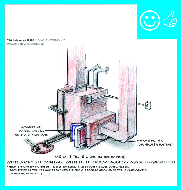
    • Use UL-approved gaskets to seal cabinet doors and access panels.
    • Seal all unused conduit knockouts with UL-listed tape or mastic.
    • Seal all fixed seams in the cabinets and all seams between the cabinet and the supply or return plenums with mastic or mastic and fiberglass mesh fabric.
    • Use a sealing putty to seal the inside of the high-voltage wire conduit termination point in the air handler after the wiring has been installed.
    • Check the insulation inside the air handler where the conduit enters. If the insulation has been compromised, repair it with approved spray glue and additional insulation.
    • Use a duct blower tester to test the airtightness of the air handler/furnace cabinet and ducts. Verify that the duct system meets code or program airtightness requirements.

    See the Compliance Tab for related codes and standards, and criteria to meet national programs such as DOE’s Zero Energy Ready Home programENERGY STAR Single-Family New Homes, and Indoor airPLUS.

    Description
    Description

    Many homes are equipped with central forced air systems that rely on ducts to transport heated or cooled air from a furnace or heat pump to the rest of the home. If the ducts are leaky, they can be a source of energy loss through loss of heated or cooled air, poor HVAC performance through loss of air pressure in the ducts, and comfort problems. Air leakage problems can be worst at the HVAC furnace or air handler cabinet, where air pressures are highest. Cabinet seams, holes, and junctions should be sealed to prevent air leakage. The only place air should be able to leave the supply duct system and the furnace or air handling unit is at the supply registers. The only place air should be able to enter the return duct system and the furnace or air handling unit is at the return grilles (Building Science Corporation 2009).

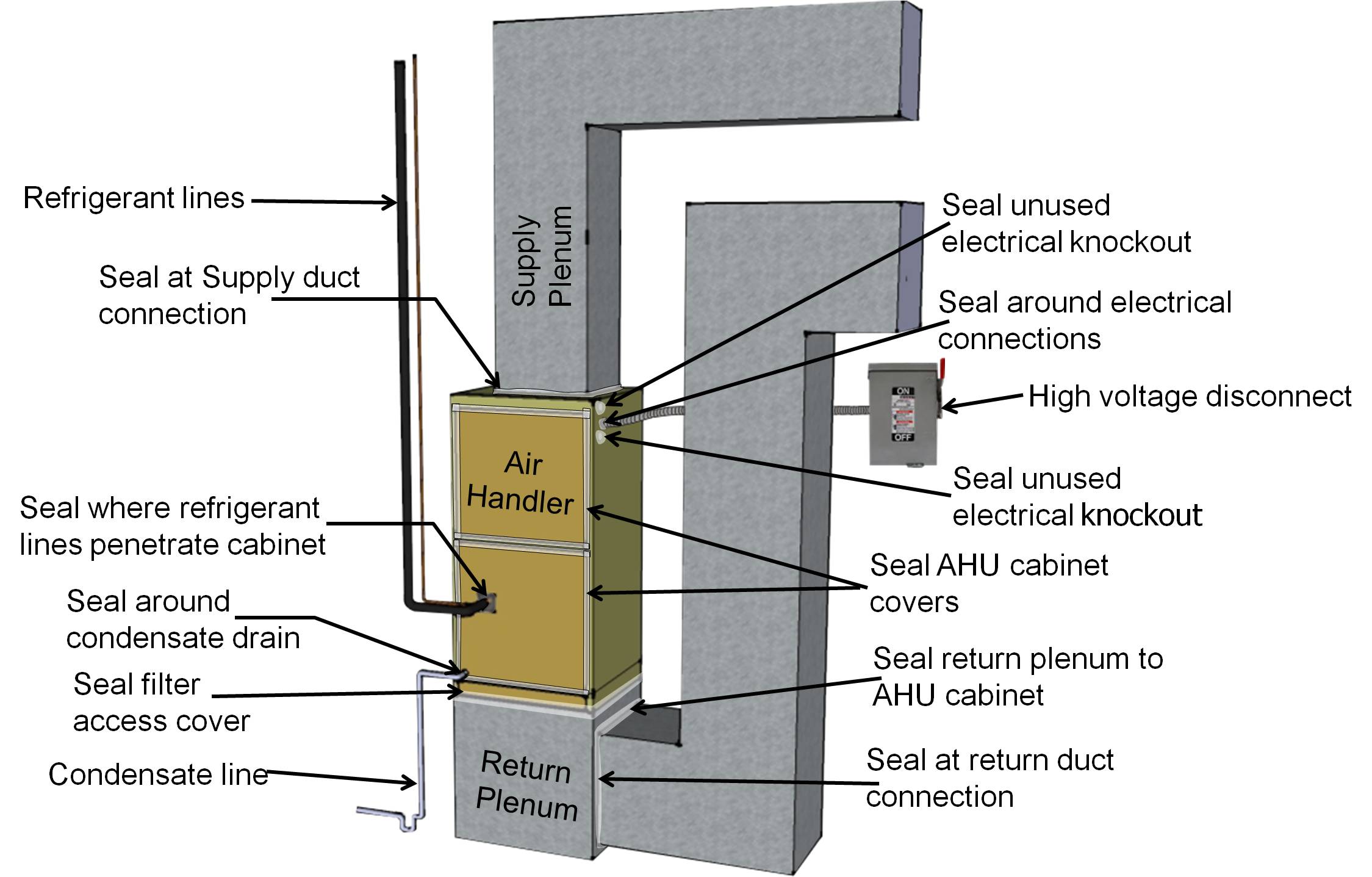
    In high-performance homes, all HVAC equipment, including the furnace or heat pump air handler and any ducts, should be located within the thermal envelope of the home. When the air handler is located within the conditioned space, it is tempting to think that sealing the cabinet is not that important because conditioned air will leak into the home rather than being lost to an attic or crawlspace. However, sealing cabinet air leaks is still very important for maximizing the performance of the HVAC equipment because it helps to ensure maximum air flow to the ducts. In a central forced air system, the highest air pressures are experienced at the air handler, with pressures increasing the closer one gets to the air handler fan. It is common for air pressures in the supply and return plenum at the air handler to equal or exceed 0.5-inches water column (125 Pascals). Therefore, it is critical to seal up the knockouts, seams, and slots in the air handler cabinet.

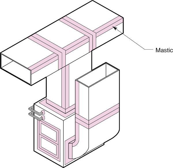
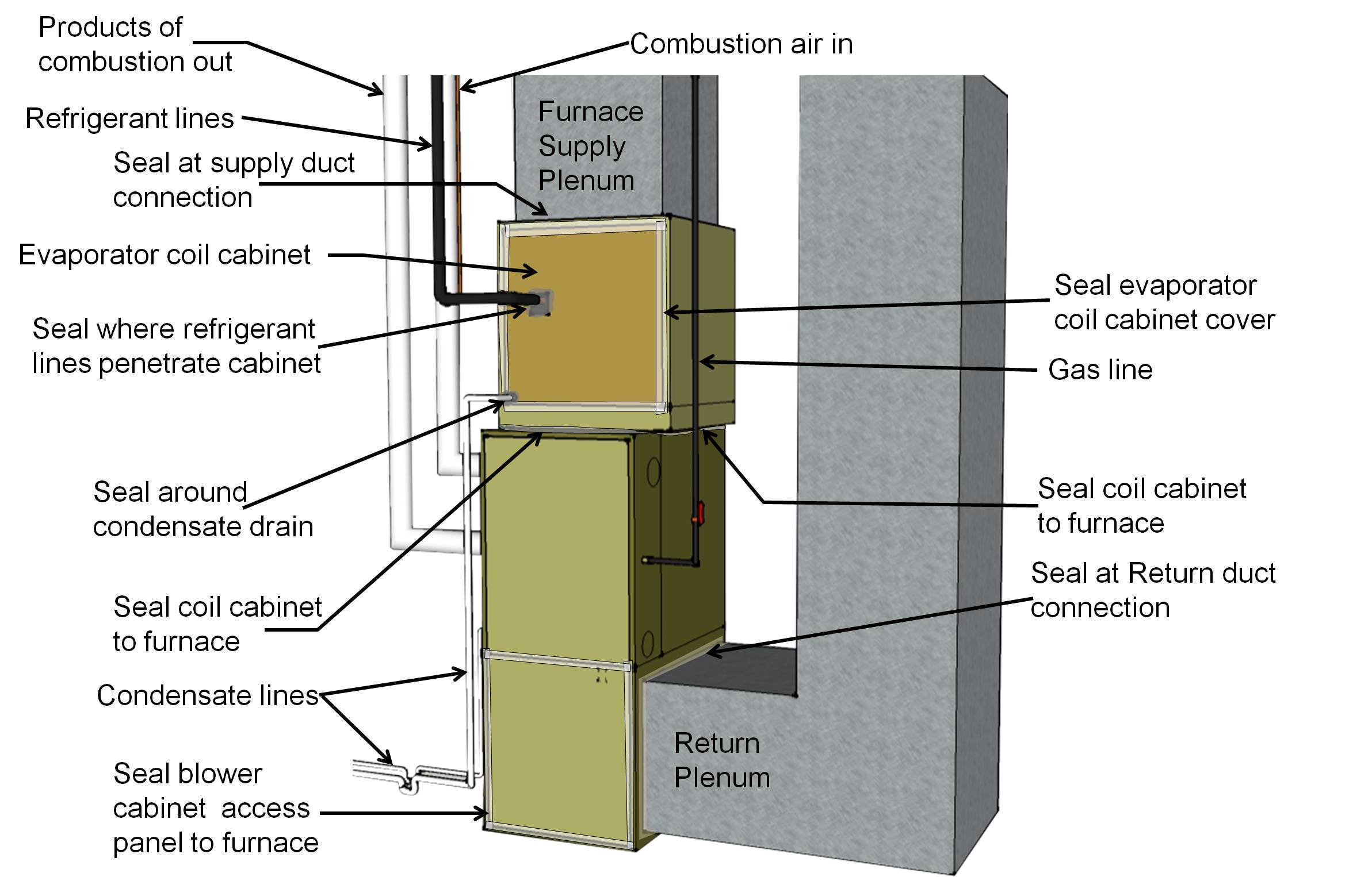
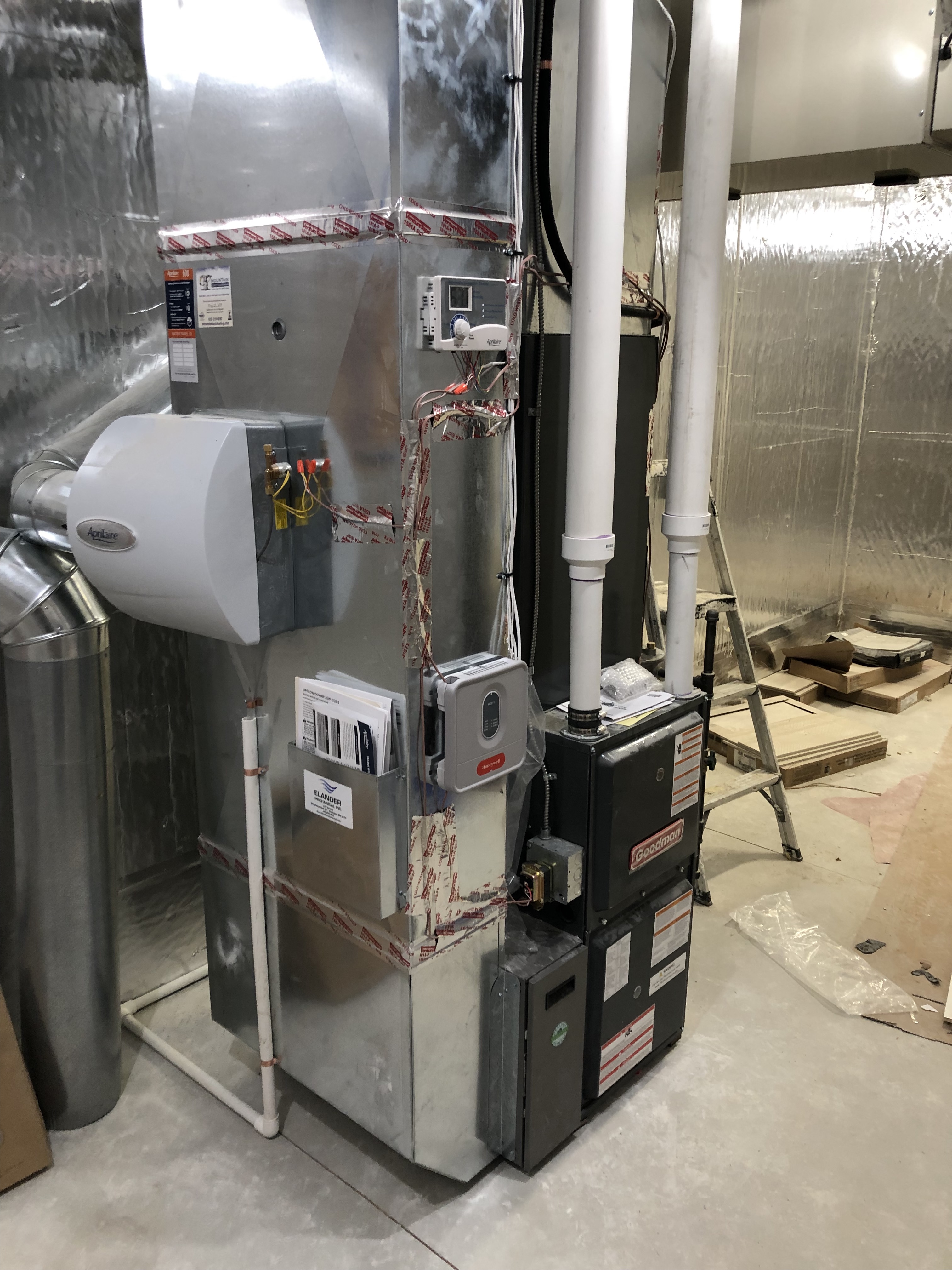
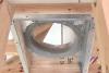
    Gas- or oil-fired furnaces are often equipped with an add-on refrigerant coil (called the evaporator coil) to provide cooling during the summer months (Figure 1). The connection between the evaporator coil cabinet and the furnace cabinet is likely the highest point of pressure in the system and can be a large source of leakage if care is not taken to properly seal this juncture during installation. Refrigerant coil cabinets do not always fit directly on top of the furnace; many coil cabinets have a larger footprint than the furnace so the seam between the two boxes is uneven. The coil cabinet should be sealed to the furnace using mastic or an Underwriters Laboratories (UL) 181 approved foil tape. For larger gaps (greater than 3/8 inch) mastic and fiberglass mesh tape should be used. 

    Air seal all holes and seams in the furnace cabinet with mastic, foil tape, or putty
    Figure 1. Air seal all holes and seams in the furnace cabinet with mastic, foil tape, or putty. Pay special attention to sealing the junction between the furnace cabinet and the evaporator coil cabinet (Source: Courtesy of Calcs Plus). 

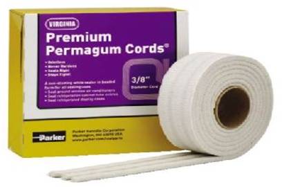
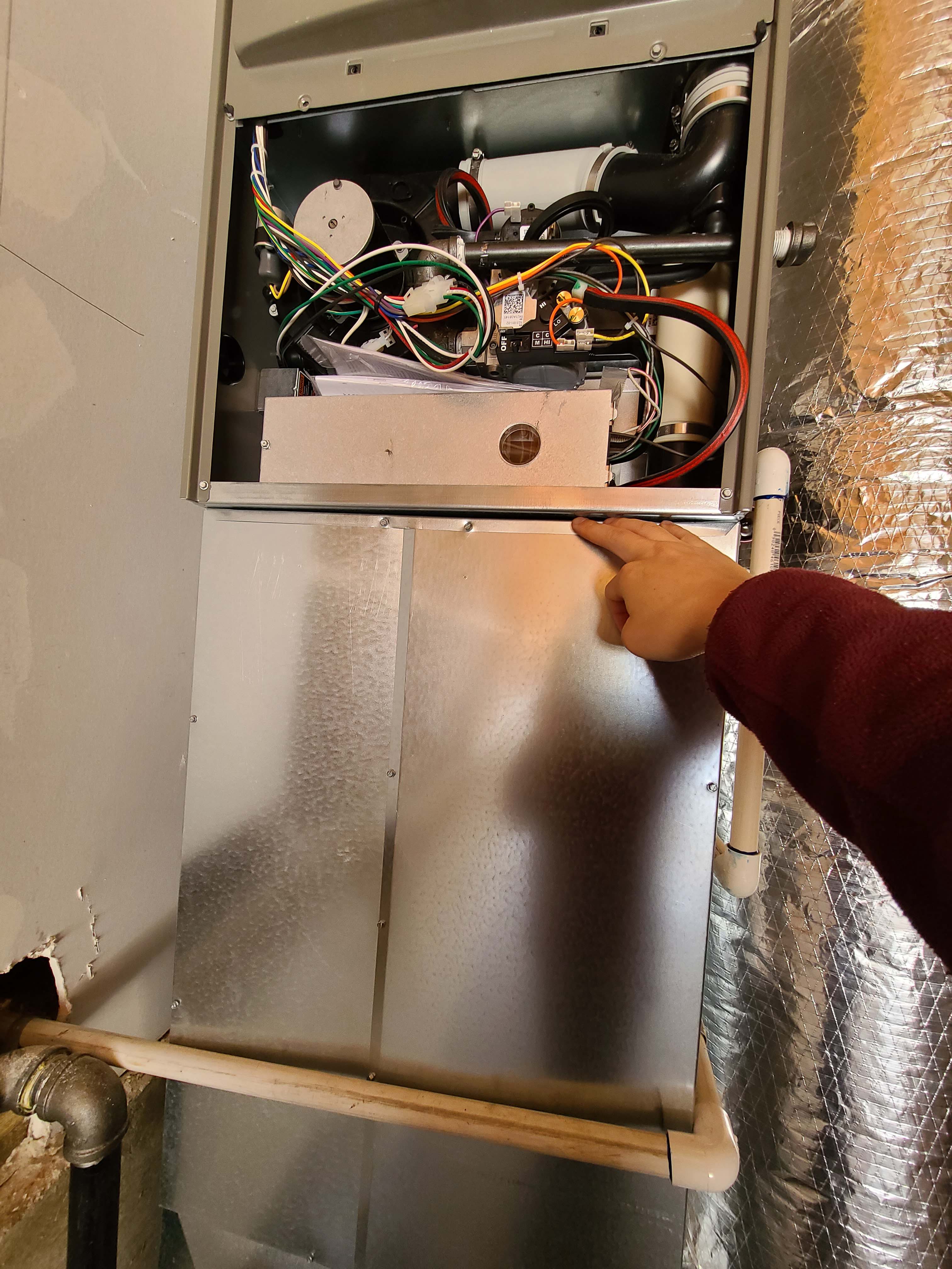
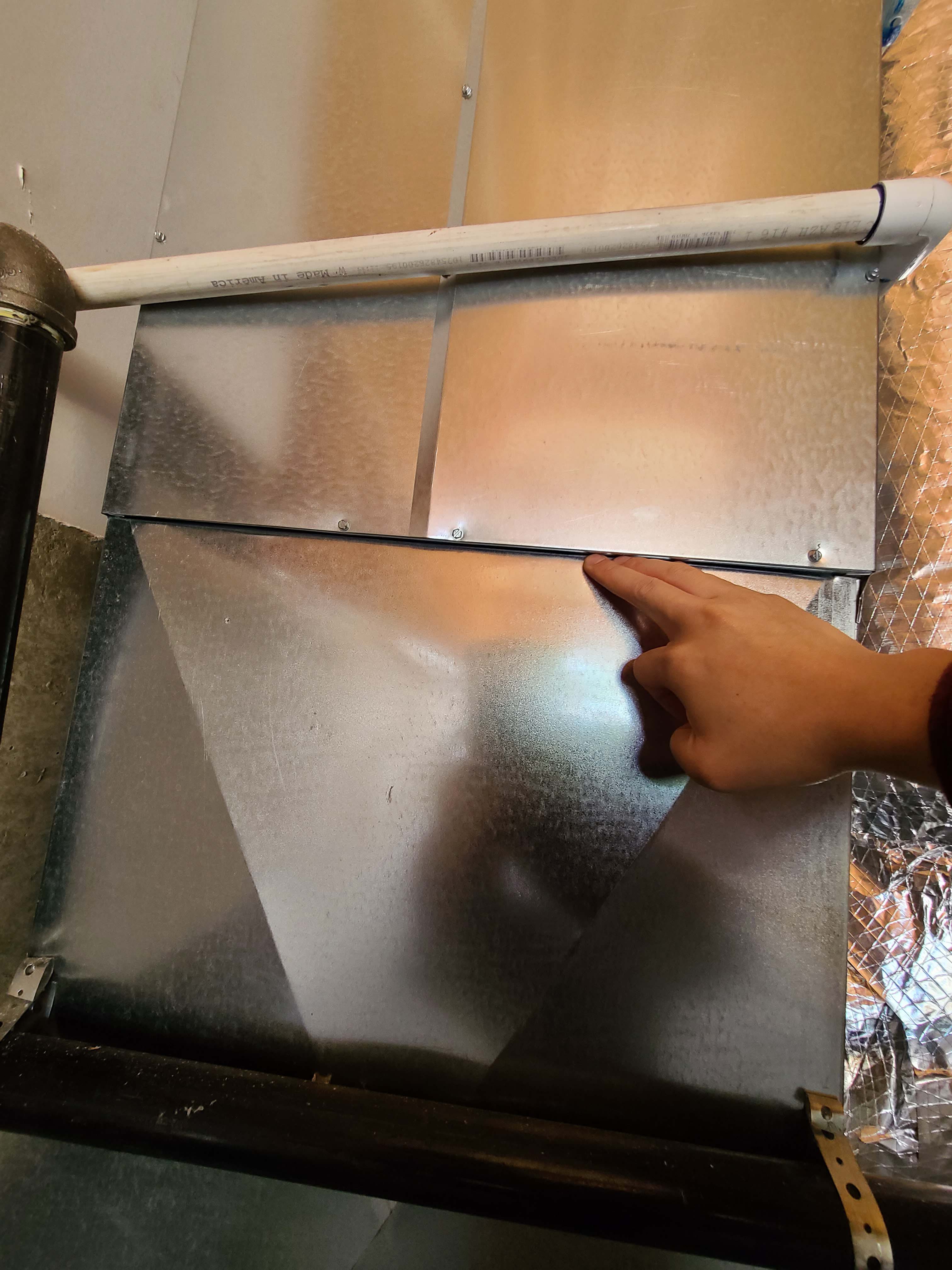
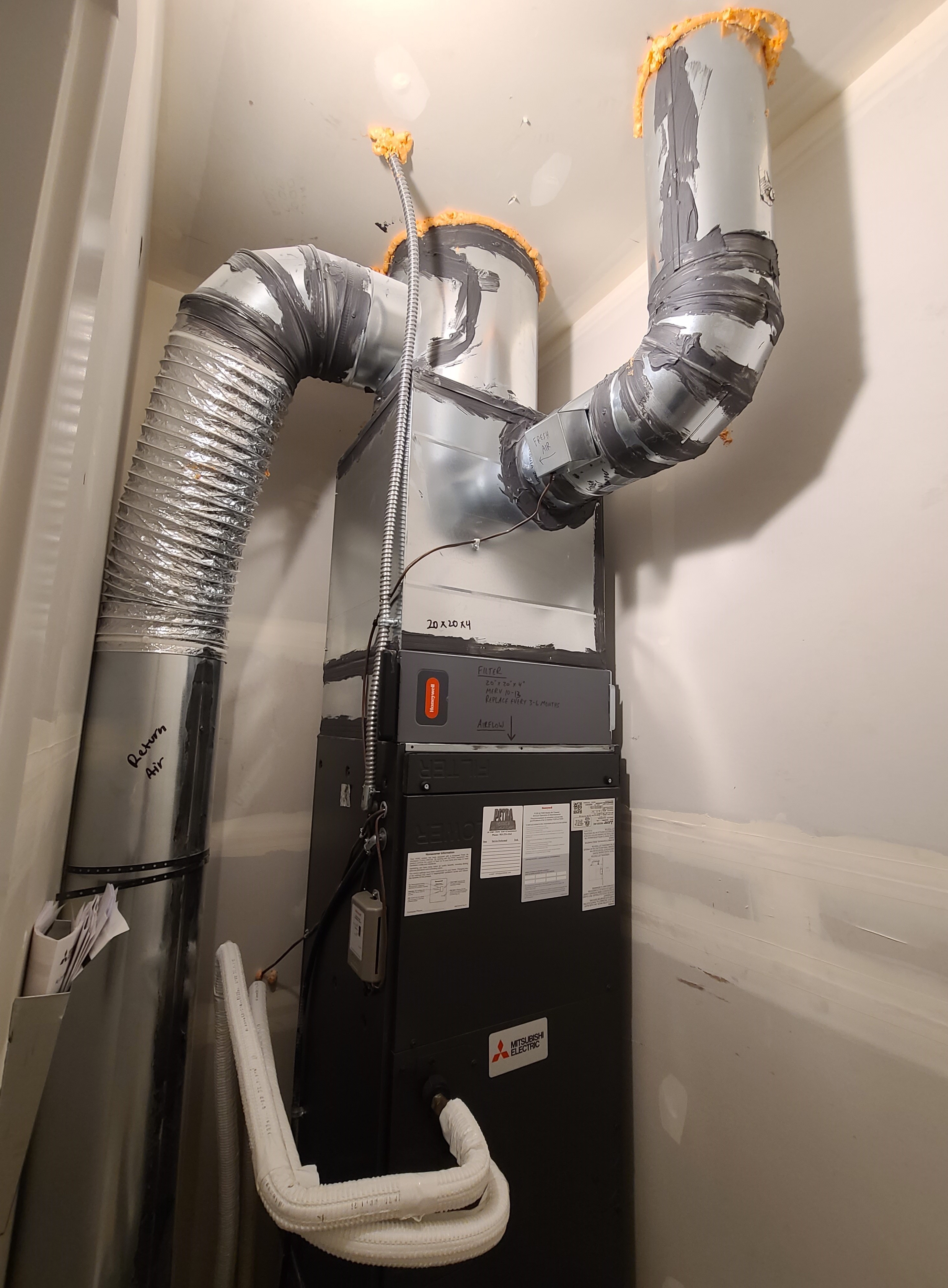
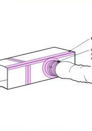
    Air handlers (Figure 2), furnaces, and evaporator coil cabinets come from the factory with holes in the form of knockouts, penetrations, and slots for installing piping and wiring. These holes are there for ease of installation and service. However, when installation is completed, any unused holes should be sealed, along with gaps around wiring and piping. Holes where the condensate line and refrigerant lines penetrate the evaporator coil cabinet will be the next highest pressure point, and depending on the model may be a point of negative pressure. Seal around these lines with non-hardening putty. Use non-hardening putty to seal around pipes, tubing, and conduit penetrations in the air handler cabinet as well. This putty comes in strips, slugs, and cords (see Figure 3) and does not dry out, but remains pliable so it can be removed and reapplied. Seal unused electrical and piping knockouts with mastic.

    The third point of high (negative) pressure is the area of the cabinet that houses the indoor blower fan. With respect to indoor air quality, this may be considered the most concerning area for air leakage, especially if the furnace is located in a garage or any other area where chemicals are stored or where there is exposure to carbon monoxide. Any seams or unused holes should be sealed with mastic.

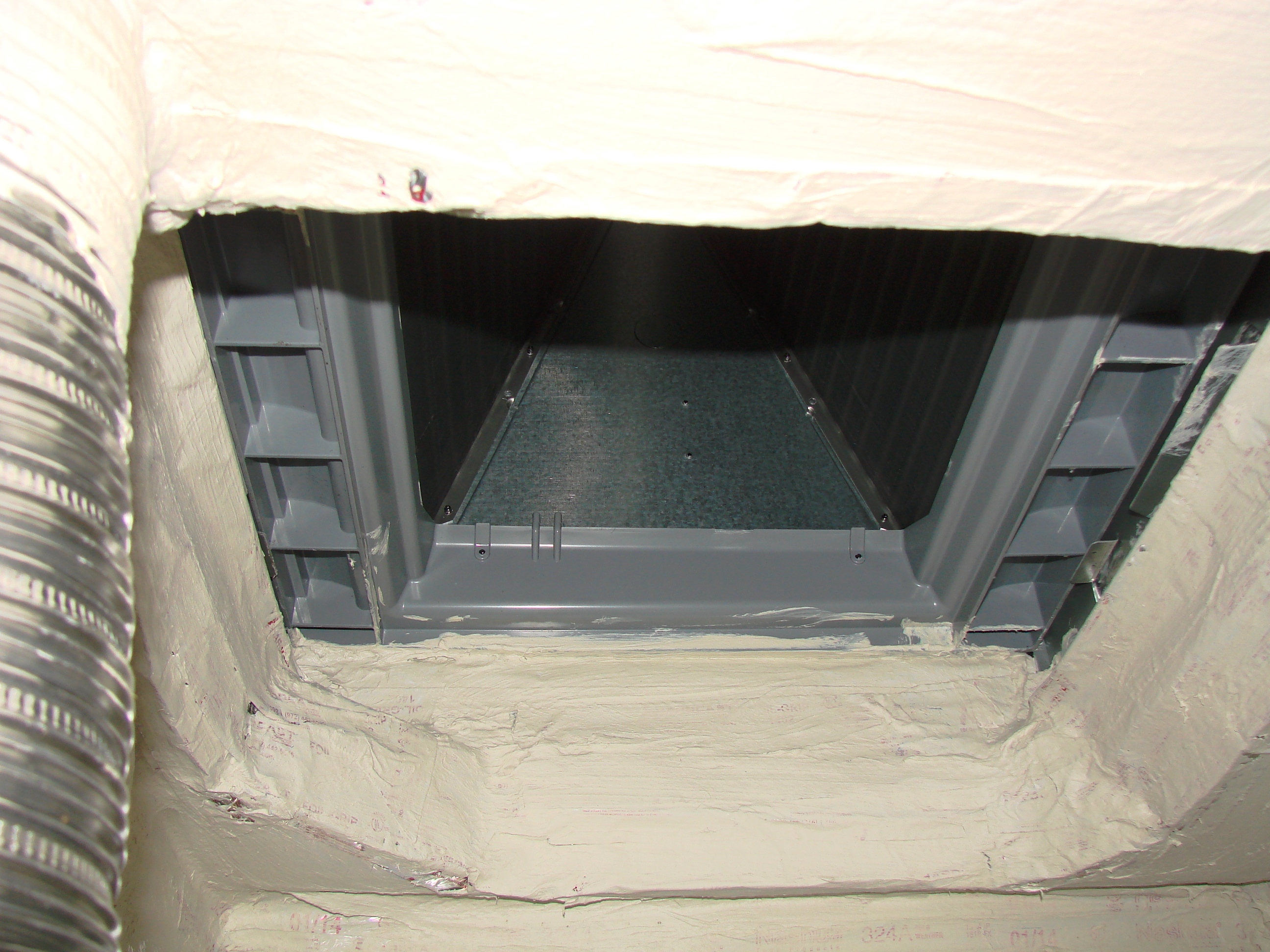
    The connections with the supply and return plenums are additional areas that experience high pressures. These seams and other cabinet seams should be sealed with mastic, mastic and fiberglass mesh tape, or UL-approved tape.

    There are some penetrations in a furnace cabinet that are not considered leakage points. The furnace in Figure 1 is a condensing gas furnace. The penetrations for the condensate line for the condensing gas furnace, vent pipes, gas line, and high voltage wiring (not shown) are not connected to the conditioned air stream and therefore are not areas of concern for leakage.

    Regarding cabinet panels that must be periodically removed for routine maintenance of the HVAC equipment, some HVAC technicians suggest using cloth-backed duct tape to seal the panel seams because it is easy to remove or cut through.

    Air seal heat pump or air conditioner air handler
    Figure 2. Air seal a heat pump or air conditioner air handler cabinet at all seams, holes, and junctions (Source: Courtesy of Calcs Plus). 


    Removable putty can also be used to seal around wiring holes
    Figure 3. Non-hardening removable putty can be used to seal around wiring holes in the HVAC cabinet (Source: Courtesy of Calcs Plus). 


    How to Air Seal the HVAC Cabinet

    1. Install the furnace or air handler and all associated ducting within the conditioned space of the home. Select an air handler with a manufacturer’s designation showing that air leakage is no more than 2% of the design air flow rate when tested in accordance with ASHRAE 193 (per 2012 IECC R403.2.2.1).
    2. Use Underwriters Laboratory (UL) approved gaskets, mastic, mastic plus embedded fiberglass mesh fabric, or UL 181A or B tape to seal all cabinet seams and junctures between the air handler or furnace cabinet and the evaporator coil cabinet, the supply plenum and the return plenum.
    3. Use putty around all conduit and wiring holes.
    4. Seal all unused conduit knockouts with UL-listed tape or mastic. Seal all fixed seams in the cabinets and all seams between the cabinet and the supply or return plenums with mastic or mastic and fiberglass mesh fabric.
    5. Use a sealing putty to seal the inside of the high-voltage wire conduit termination point in the air handler after the wiring has been installed.
    6. Check the insulation inside the air handler where the conduit enters. If the insulation has been compromised, repair it with approved spray glue and additional insulation.
    7. Use a duct blower tester to test the airtightness of the air handler/furnace cabinet and ducts. Verify that the duct system meets code or program airtightness requirements.
    Success
    Ensuring Success

    Install the air handler within the conditioned space of the home.

    Seal all seams and holes in the air handler cabinet.

    Test the airtightness of the cabinets and ducts with a duct blower test. Verify that the duct system meets code or program airtightness requirements.

    Climate
    Climate

    No climate specific information applies.

    Training
    Right and Wrong Images
    Image
    Right – All of the cabinet seams in this HVAC air furnace are sealed with an approved metal tape.
    Right – All of the cabinet seams in this HVAC air furnace are sealed with an approved metal tape.
    Image
    Right – HVAC furnace filter is properly installed in cabinet with gasketed cover to prevent air leakage
    Right – HVAC furnace filter is properly installed in cabinet with gasketed cover to prevent air leakage
    Image
    Right: The bottom of the air handler cabinet is well sealed to the return platform
    Right: The bottom of the air handler cabinet is well sealed to the return platform
    Image
    Right – All of the cabinet seams in this HVAC air furnace are sealed with an approved metal tape.
    Right – All of the cabinet seams in this HVAC air furnace are sealed with an approved metal tape.
    Image
    Wrong - HVAC metal cabinet seam is not sealed with mastic or metal tape.
    Wrong - HVAC metal cabinet seam is not sealed with mastic or metal tape.
    Image
    Wrong - HVAC rigid metal duct seam needs top be air sealed with mastic or metal tape.
    Wrong - HVAC rigid metal duct seam needs top be air sealed with mastic or metal tape.
    Image
    Right - Ducts and heat pump cabinet are properly sealed with mastic, high MERV filter is installed, and duct and refrigerant lines are air sealed at ceiling.
    Right - Ducts and heat pump cabinet are properly sealed with mastic, high MERV filter is installed, and duct and refrigerant lines are air sealed at ceiling.
    Presentations
    Videos
    Compliance

    Compliance

    The Compliance tab contains both program and code information. Code language is excerpted and summarized below. For exact code language, refer to the applicable code, which may require purchase from the publisher. While we continually update our database, links may have changed since posting. Please contact our webmaster if you find broken links.


    ENERGY STAR Single-Family New Homes, Version 3/3.1 (Rev. 11)

    National Rater Field Checklist

    HVAC System.
    6. Duct Quality Installation - Applies to Heating, Cooling, Ventilation, Exhaust, & Pressure Balancing Ducts, Unless Noted in Footnote.
    6.4 Rater-measured total duct leakage meets one of the following two options. Alternative in Footnote 40:39, 40, 41
    6.4.1 Rough-in: The greater of ≤ 4 CFM25 per 100 sq. ft. of CFA or ≤ 40 CFM25, with air handler & all ducts, building cavities used as ducts, & duct boots installed. All duct boots sealed to finished surface, Rater-verified at final.42
    6.4.2 Final: The greater of ≤ 8 CFM25 per 100 sq. ft. of CFA or ≤ 80 CFM25, with the air handler & all ducts, building cavities used as ducts, duct boots, & register grilles atop the finished surface (e.g., drywall, floor) installed.43
    6.5 Rater-measured duct leakage to outdoors the greater of ≤ 4 CFM25 per 100 sq. ft. of CFA or ≤ 40 CFM25.39, 44

    Footnote 39) Items 6.4 and 6.5 generally apply to the ducts of space heating, space cooling, and dwelling unit mechanical ventilation systems. However, visual inspection is permitted in lieu of testing for a dwelling unit mechanical ventilation system not connected to the space heating or space cooling system, regardless of the number of dwelling units it serves. In such cases, a Rater shall visually verify that all seams and connections are sealed with mastic or metal tape and all duct boots are sealed to floor, wall, or ceiling using caulk, foam, or mastic tape. For duct systems requiring testing, duct leakage shall be determined and documented by a Rater using ANSI / RESNET / ICC Std. 380 including all Addenda and Normative Appendices, with new versions and Addenda implemented according to the schedule defined by the HCO that the home is being certified under. Leakage limits shall be assessed on a per-system, rather than per-home, basis.

    Footnote 40) For a duct system with three or more returns, the total Rater-measured duct leakage is permitted to be the greater of ≤ 6 CFM25 per 100 sq. ft. of CFA or ≤ 60 CFM25 at ‘rough-in’ or the greater of ≤ 12 CFM25 per 100 sq. ft. of CFA or ≤ 120 CFM25 at ‘final’.

    Footnote 41) Note that compliance with Item 6.4.1 or 6.4.2 in conjunction with Section 4a of the National Rater Design Review Checklist automatically achieves Grade I total duct leakage per ANSI / RESNET / ACCA Std. 310.

    Footnote 42) Cabinets (e.g., kitchen, bath, multimedia) or ducts that connect duct boots to toe-kick registers are not required to be in place during the ‘rough-in’ test.

    Footnote 43) Registers atop carpets are permitted to be removed and the face of the duct boot temporarily sealed during testing. In such cases, the Rater shall visually verify that the boot has been durably sealed to the subfloor (e.g., using duct mastic or caulk) to prevent leakage during normal operation.

    Footnote 44) Testing of duct leakage to the outdoors can be waived in accordance with the 2nd or 3rd alternative of ANSI / RESNET / ICC Std. 301, Table 4.2.2 (1), footnote (w). Alternatively, testing of duct leakage to outdoors can be waived in accordance with Section 5.5.2 of ANSI / RESNET / ICC Std. 380 if total duct leakage, at rough-in or final, is ≤ 4 CFM25 per 100 sq. ft. of conditioned floor area or 40 CFM25, whichever is larger. Guidance to assist partners with these alternatives, including modeling inputs, is available at http://www.energystar.gov/newhomesguidance.

    Many states have adopted state- or region-specific ENERGY STAR Single-Family New Homes criteria - Please see the ENERGY STAR Single-Family New Homes Implementation Timeline for regional specifications.


    DOE Zero Energy Ready Home (Revision 07)

    Exhibit 1 Mandatory Requirements.
    Exhibit 1, Item 1) Certified under the ENERGY STAR Qualified Homes Program or the ENERGY STAR Multifamily New Construction Program.
    Exhibit 1, Item 3) Duct distribution systems located within the home’s thermal and air barrier boundary or an optimized location to achieve comparable performance.
    Exhibit 1, Item 6) Certified under EPA Indoor airPLUS.

    Footnote 14) Exceptions and alternative compliance paths to locating 100% of forced-air ducts in home’s thermal and air barrier boundary are:

    1. Up to 10’ of total duct length is permitted to be outside of the home’s thermal and air barrier boundary.
    2. Ducts are located in an unvented attic, regardless of whether this space is conditioned with a supply register.
    3. Ducts are located in a vented attic with all of the following characteristics: [​Note that in either of these designs the HVAC equipment must still be located within the home’s thermal and air barrier boundary.
      1. In Moist climates (Zones 1A, 2A, 3A, 4A, 5A, 6A and 7A per 2015 IECC Figure R301.1) and Marine climates (all “C” Zones per 2015 IECC Figure R301.1), minimum R-8 duct insulation with an additional minimum 1.5” of closed-cell spray foam insulation encapsulating the ducts; duct leakage to outdoors ≤ 3 CFM25 per 100 ft2 of conditioned floor area (in addition to meeting total duct leakage requirements from Section 4.1 of the ENERGY STAR HVAC Rater checklist); and ductwork buried under at least 2” of blown-in insulation.
      2. In Dry climates (all “B” Zones per 2015 IECC Figure R301.1), minimum R-8 duct insulation; duct leakage to outdoors ≤ 3 CFM25 per 100 ft2 of conditioned floor area (in addition to meeting total duct leakage requirements from Section 4.1 of the ENERGY STAR HVAC Rater checklist); and ductwork buried under at least 3.5” of blown-in insulation.
    4. Systems which meet the criteria for “Ducts Located in Conditioned Space” as defined by the 2018 IECC Section R403.3.7
    5. Jump ducts which do not directly deliver conditioned air from the HVAC unit may be located in attics if all joints, including boot-to-drywall, are fully air sealed with mastic or foam, and the jump duct is fully buried under the attic insulation.
    6. Ducts are located within an unvented crawl space.
    7. Ducts are located in a basement which is within the home’s thermal boundary.
    8. Ductless HVAC system is used.

    Please see the DOE Zero Energy Ready Home website for state-specific requirements.


    EPA Indoor airPLUS (Revision 04)

    4.2 Duct System Design and Installation. Indoor airPLUS requires that homes meet ENERGY STAR for Homes criteria including the requirement that all duct systems are installed to be substantially airtight. Indoor airPLUS advises that seams in the HVAC cabinet, plenum and adjacent ductwork should be sealed with mastic systems, tape that meets the applicable requirements of UL 181a or UL 181b, or gasket systems.


    2009, 2012, 2015, 2018, and 2021 International Energy Conservation Code (IECC)

    R403.3.4 (R403.3.2 in 2015, 2018 and R403.2.2 in 2012, 2009 IECC) Ducts. Sealing (Mandatory).  All ducts, air handlers, filter boxes, and building cavities used as ducts should be sealed. Duct tightness should be verified by duct leakage testing (testing is not required if the air handler and all ducts are in conditioned space). Testing can be done at rough-in or when construction is complete.

    If testing is done at rough-in, total leakage must be ≤ 4 cfm/100 sq. ft.  ( ≤ 6 cfm in 2009 IECC) of conditioned floor area when tested at a pressure difference of 25 Pa across the roughed in system including the manufacturer’s air handler enclosure, with all register boots sealed. If the air handler is not installed at the time of the test, total air leakage must be ≤ 3 cfm/100 sq. ft. ( ≤ 4 cfm in 2009 IECC)of conditioned floor area.

    If testing is done post construction, leakage to outdoors must be ≤ 4 cfm/100 sq. ft. (≤ 8 cfm/100 sq. ft. in 2009 IECCC) of conditioned floor area at 25 Pa across the system including the air handler enclosure.

    In 2021 IECC, Section R403.3.6, where all ducts and air handlers are located entirely within the building thermal envelope, total leakage shall be ≤ 8cfm/100sq. ft. of conditioned floor area.

    R403.3.2.1 (R403.3.2.1 in 2015, 2018 IECC and R403.2.2.1 in 2012 IECC) Sealed air handler. The air handler should have a manufacturer’s designation showing that air leakage is no more than 2% of the design air flow rate when tested in accordance with ASHRAE 193.

    Retrofit:  2009, 2012, 2015, 2018,  and 2021 IECC

    Section R101.4.3 (in 2009 and 2012). Additions, alterations, renovations, or repairs shall conform to the provisions of this code, without requiring the unaltered portions of the existing building to comply with this code. (See code for additional requirements and exceptions.)

    Chapter 5 (in 2015, 2018, 2021). The provisions of this chapter shall control the alteration, repair, addition, and change of occupancy of existing buildings and structures.


    2009, 2012, 2015, 2018, and 2021 International Residential Code (IRC)

    M1601.4.1 Duct Installation: Joints and Seams. The joints of duct systems shall be made airtight by means of tapes, mastics, liquid sealants, gaskets, or other approved closure systems. The 2012-2021 IRC includes welds and mastic plus embedded fabric as joint seam materials and specifies that tape must be UL-181-approved.

    Retrofit:  2009, 2012, 2015, 2018,  and 2021 IRC

    Section R102.7.1 Additions, alterations, or repairs. Additions, alterations, renovations, or repairs shall conform to the provisions of this code, without requiring the unaltered portions of the existing building to comply with the requirements of this code, unless otherwise stated. (See code for additional requirements and exceptions.)

    Appendix J regulates the repair, renovation, alteration, and reconstruction of existing buildings and is intended to encourage their continued safe use.


    2012, 2015, 2018, and 2021 International Mechanical Code (IMC)

    603.9 Joints, seams and connections. Securely fasten all joints, seams, and connections with welds, gaskets, mastics, mastic plus embedded fabric, liquid sealants, or tapes that are listed and in accordance with Underwriters Laboratory: For connecting rigid duct use UL 181A products marked "181A-P” for pressure-sensitive tape, "181 A-M” for mastic, or "181 A-H” for heat-sensitive tape. For flexible ducts use UL 181B sealants marked "181B-FX” for pressure-sensitive tape or "181B-M” for mastic. The connections of ducts to the flanges of air distribution system equipment should be sealed and mechanically fastened.

    More

    More Info.

    Access to some references may require purchase from the publisher. While we continually update our database, links may have changed since posting. Please contact our webmaster if you find broken links.

    Case Studies
    References and Resources*
    Author(s)
    Air Conditioning Contractors of America
    Organization(s)
    ACCA
    Publication Date
    Description
    Document detailing the requirements, roles, and obligations for participants in an organized effort, ensuring that HVAC installations comply with the ANSI/ACCA 5 QI – 2010 (HVAC Quality Installation Specification) QI Standard.
    Author(s)
    Air Conditioning Contractors of America
    Organization(s)
    ACCA
    Publication Date
    Description
    Standard providing a universally accepted definition for quality installation for residential and commercial heating, ventilating, and air conditioning applications.
    Author(s)
    Air Conditioning Contractors of America
    Organization(s)
    ACCA
    Publication Date
    Description
    The Technician's Guide equips practitioners with the knowledge to properly implement all of the measurement procedures required in the HVAC QI Specification.
    Author(s)
    Air Conditioning Contractors of America
    Organization(s)
    ACCA
    Publication Date
    Description
    Standard outlining industry procedure for sizing residential duct systems.
    Author(s)
    Beal David,
    McIlvaine Janet E R,
    Fonorow Ken,
    Martin Eric
    Organization(s)
    Building America Partnership for Improved Residential Construction,
    BA-PIRC,
    National Renewable Energy Laboratory,
    NREL,
    Florida Solar Energy Center,
    FSEC
    Publication Date
    Description
    Document illustrating guidelines for efficient installation of interior duct systems in new housing.
    Author(s)
    Building Science Corporation
    Organization(s)
    BSC
    Publication Date
    Description
    Brochure with details on HVAC duct air sealing.
    Author(s)
    U.S. Environmental Protection Agency
    Organization(s)
    EPA
    Publication Date
    Description
    Document outlining specifications that were developed by the U.S. Environmental Protection Agency (EPA) to recognize new homes equipped with a comprehensive set of indoor air quality (IAQ) features.
    *For non-dated media, such as websites, the date listed is the date accessed.
    Contributors to this Guide

    The following authors and organizations contributed to the content in this Guide.

    Sales
    Building Science Measures
    Building Science-to-Sales Translator

    Tight Duct Sealing =

    Image(s)
    Technical Description

    As conditioned air flows from heating and cooling equipment to the spaces where people live, excessive leaks compromise comfort, health, and durability while increasing energy costs. This is because conditioned air escapes ducts supplying heating and cooling, and potentially contaminated air is pulled into the ducts, returning air to the heating and cooling equipment. Professionally sealed comfort delivery systems are significantly air-tight at all seams and connections. Sealing helps conditioned air get where it is needed, at the correct temperature, without pulling in contaminants from crawlspaces and attics.


    Sales Message
    Last Updated

    Mobile Field Kit

    The Building America Field Kit allows you to save items to your profile for review or use on-site.

    Sign Up  or  Log In

    Did you find this information helpful?

    If you have questions and/or would like a reply to this feedback, please include your e-mail address in the message.
    This question is for testing whether or not you are a human visitor and to prevent automated spam submissions.