Showing results 101 - 200 of 274
Image
Image
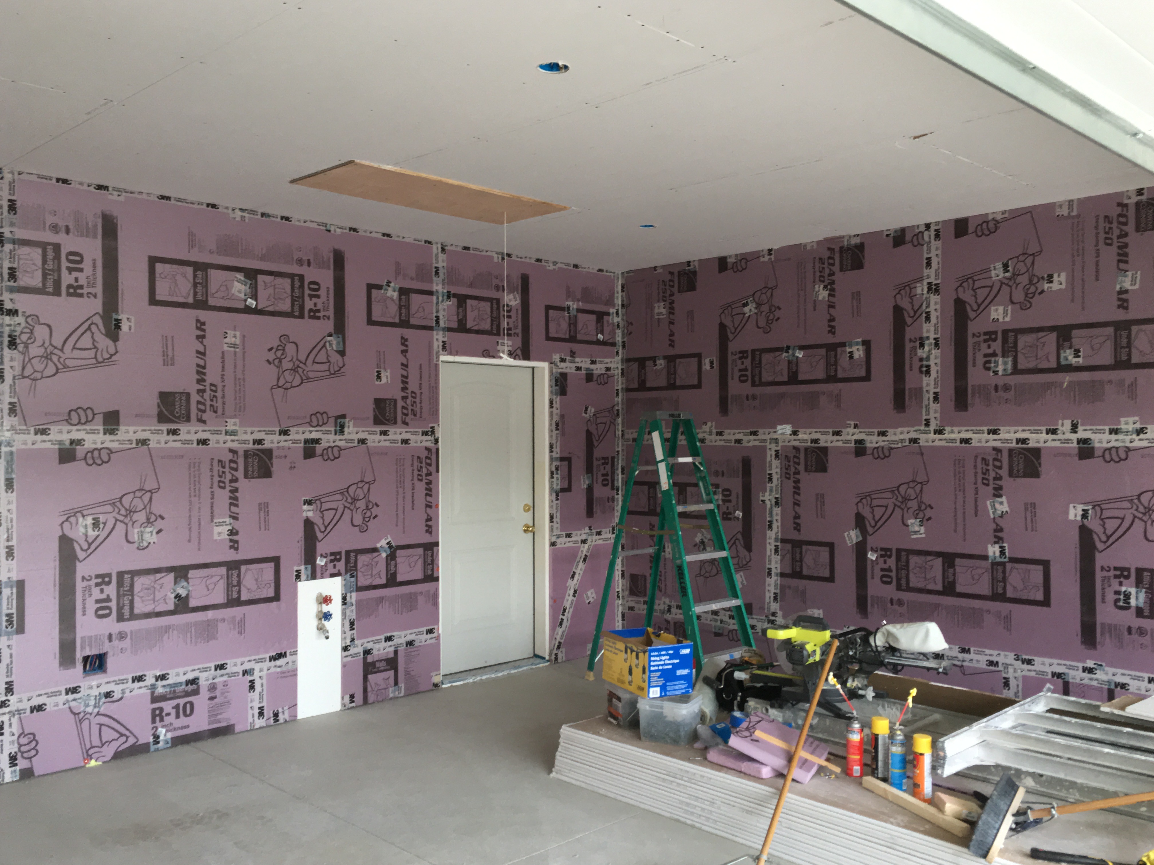
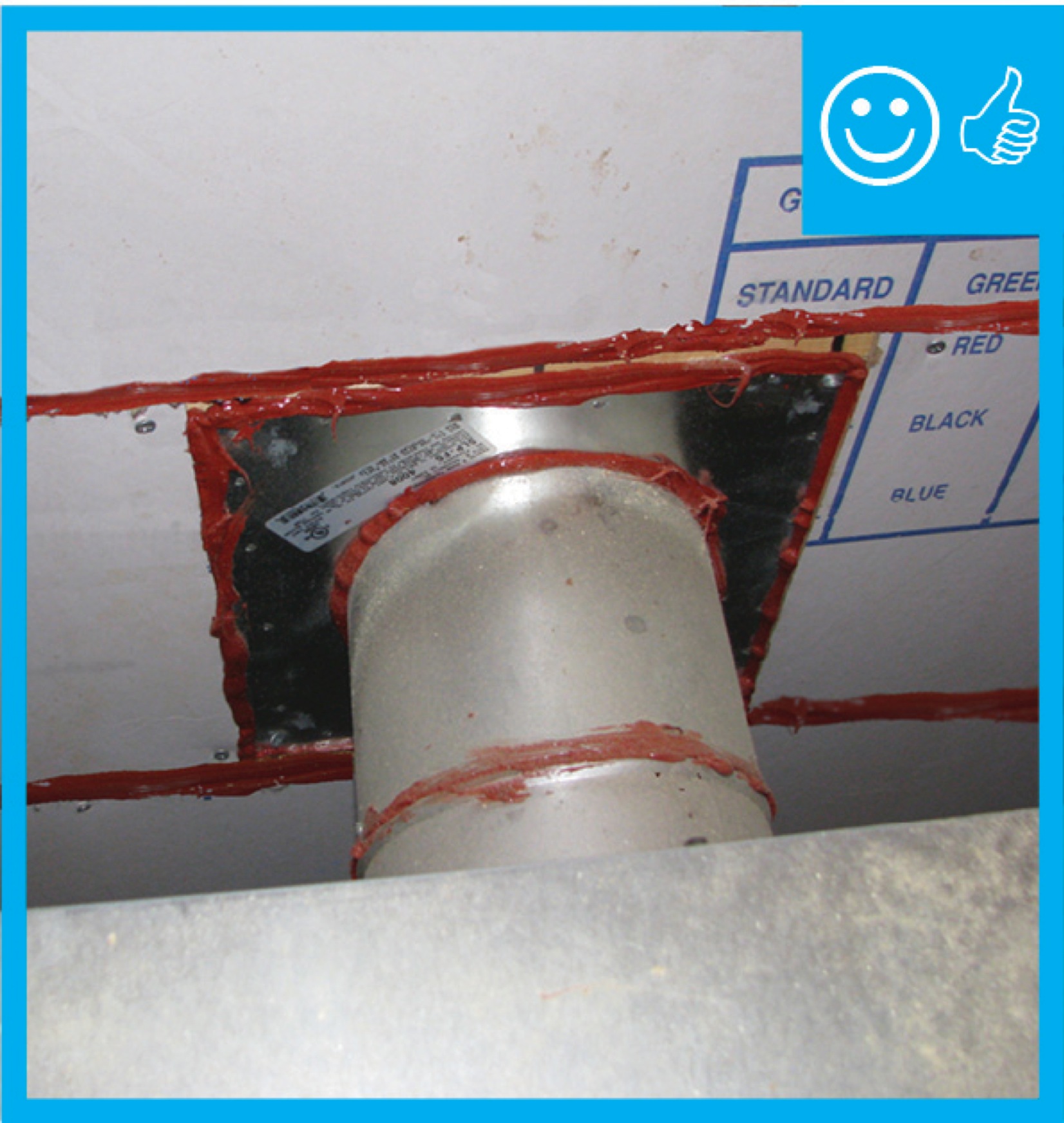
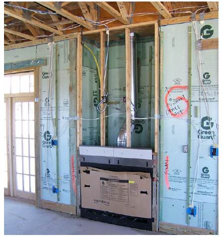
Right – Every seam and nail hole in these garage-to-house walls is sealed with tape.
Image

Image

Image
Image
Image

Image
Image
Image
Image
Image
Image
Image
Image
Image
Image
Right – The building felt is installed on all exterior walls and provides a complete drainage system
Image
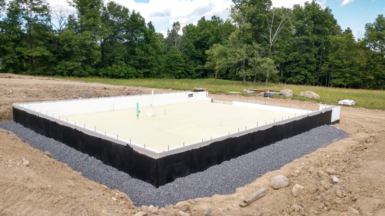
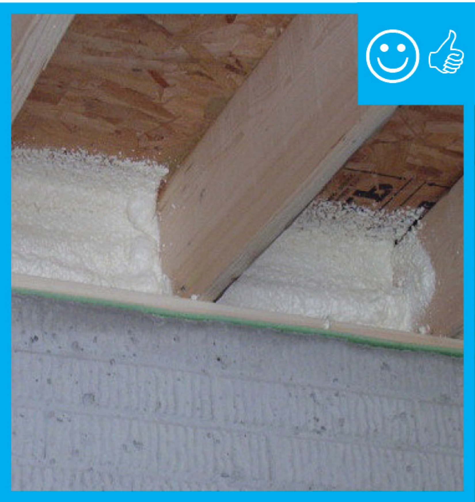
Right – The foundation of this ICF home was constructed of ICFs that were set in place on a gravel bed, then 3.5 inches (R-36) of closed-cell spray foam was sprayed directly onto the gravel, providing an effective air, vapor, and thermal barrier.
Image
Image
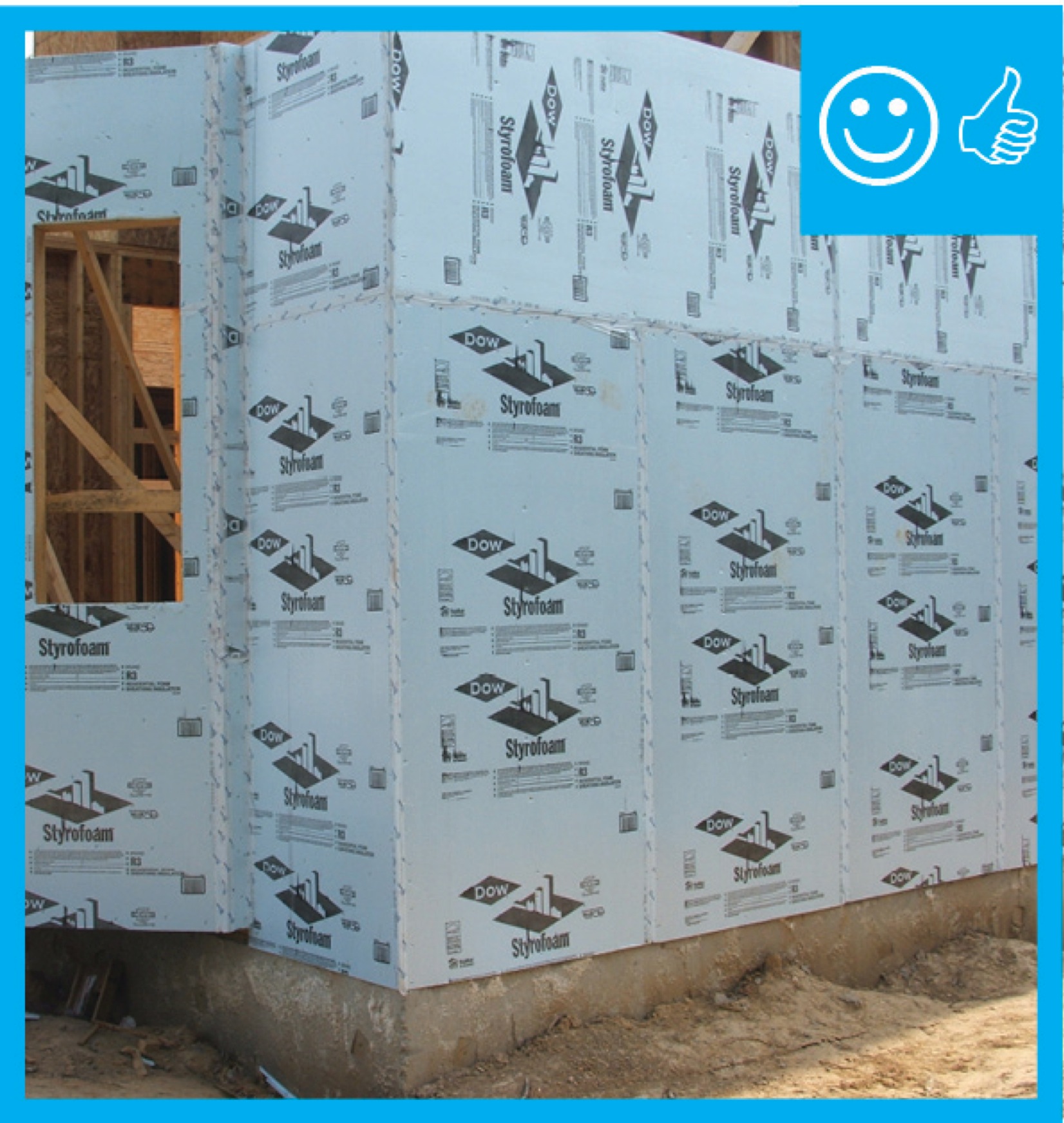
Right – The rigid insulation covers all exterior walls and all seams are taped to provide a complete drainage system
Image
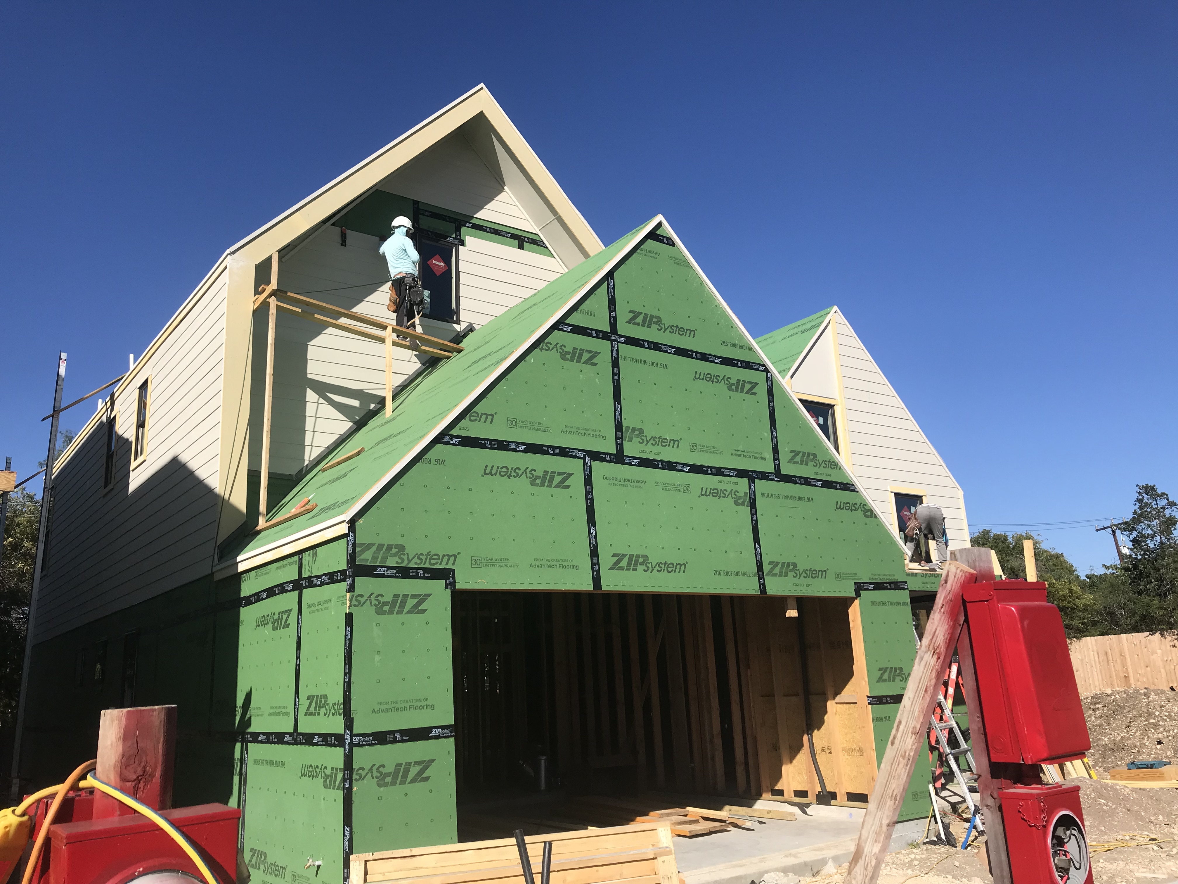
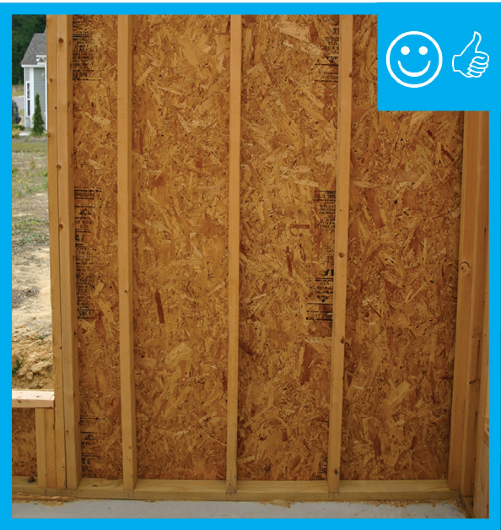
Right – The seams are taped on the coated OSB sheathing of this home to provide a complete air barrier.
Image
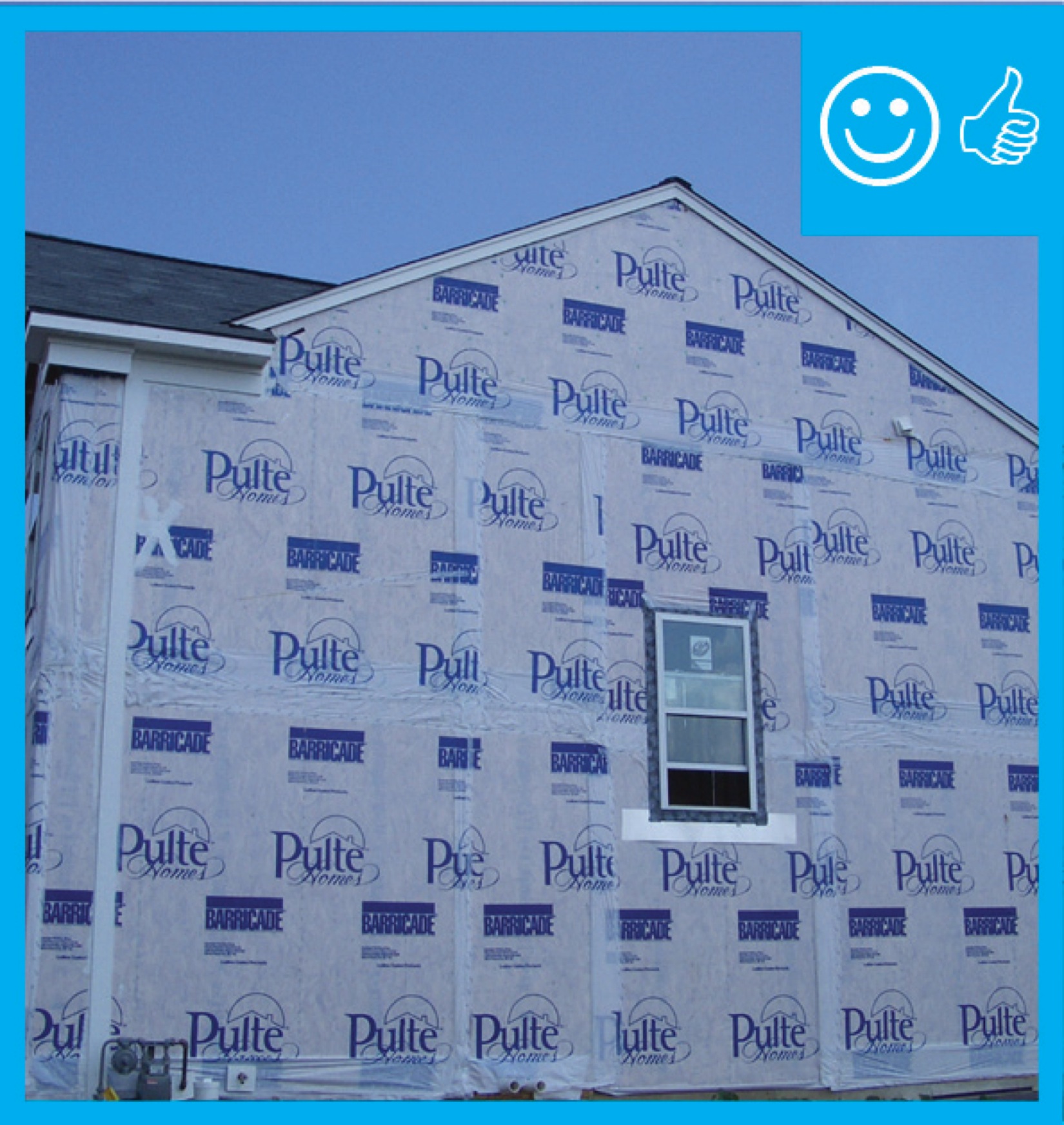
Right – The water-resistant barrier covers the entire house and the seams are taped to provide a complete drainage system
Image

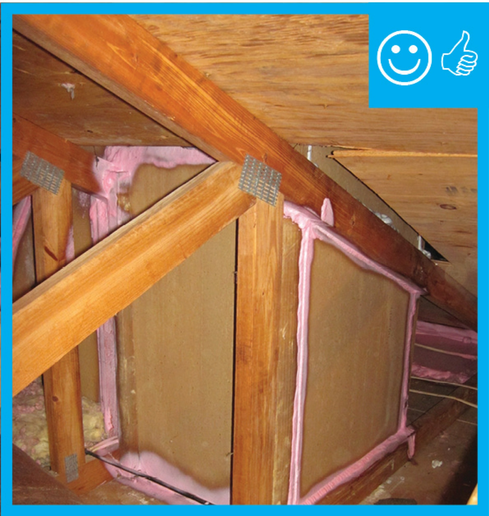
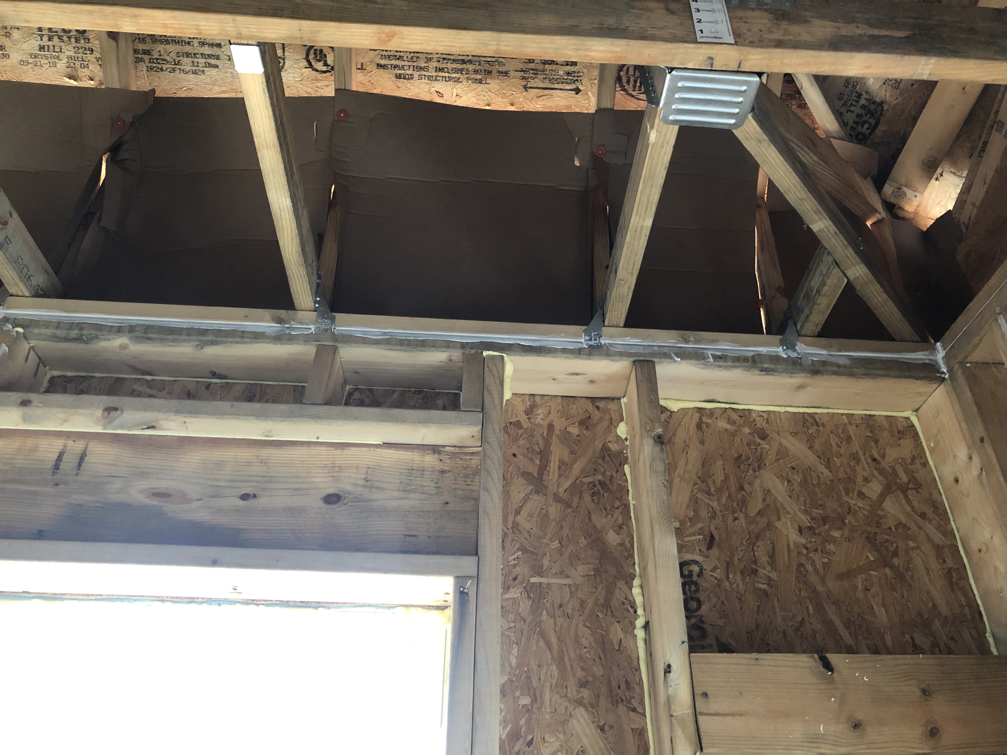
Right – This attic knee wall and the floor joist cavity openings beneath it are being sealed and insulated with spray foam.
Image
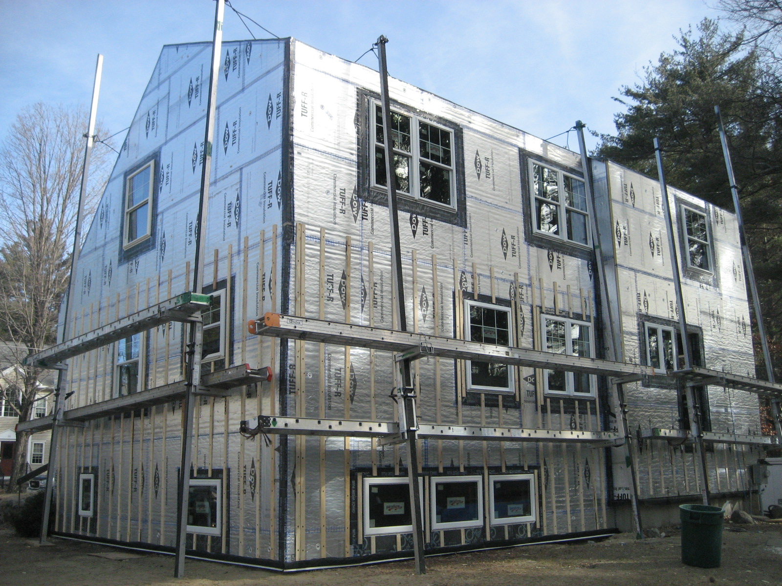
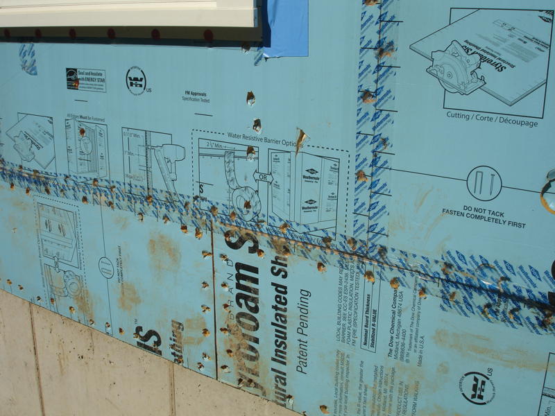
Right – This foil-faced foam sheathing has taped seams and proper flashing details so it can serve as a drainage plane.
Image
Image
Image
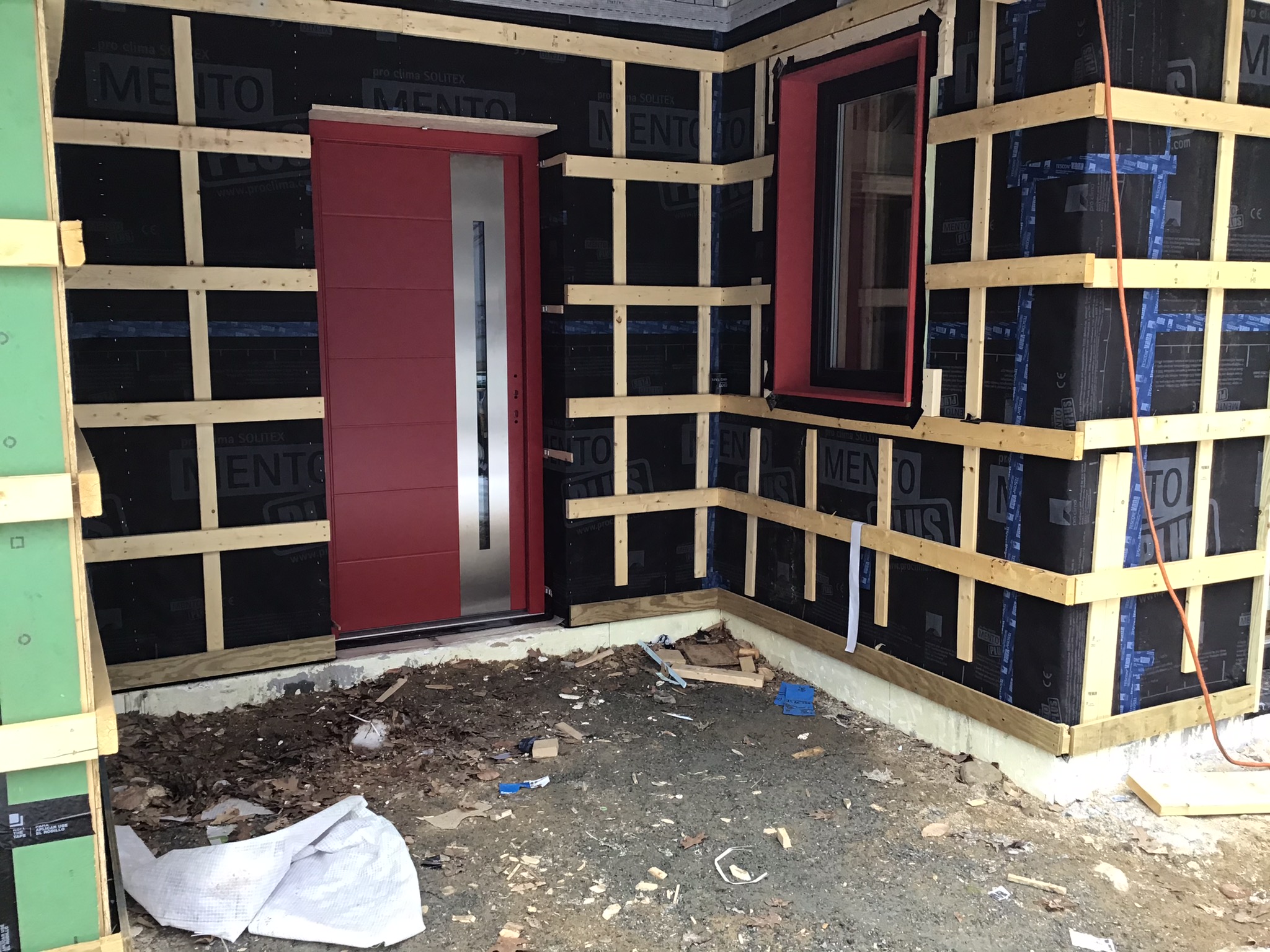
Right – Vertical and horizontal furring strips are installed over a breathable membrane weather resistant barrier to create an air gap and drainage plane behind the wood siding that will be installed next.
Image
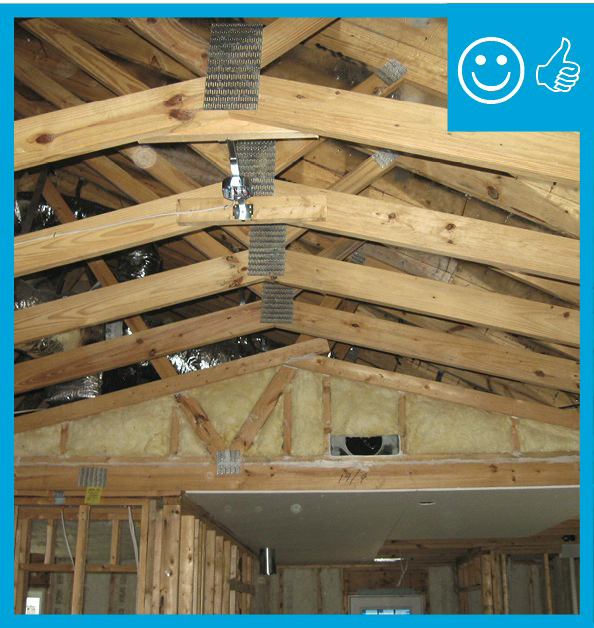
Right – Wind baffle installation maintains necessary code clearance between baffle and roof deck
Image
Image
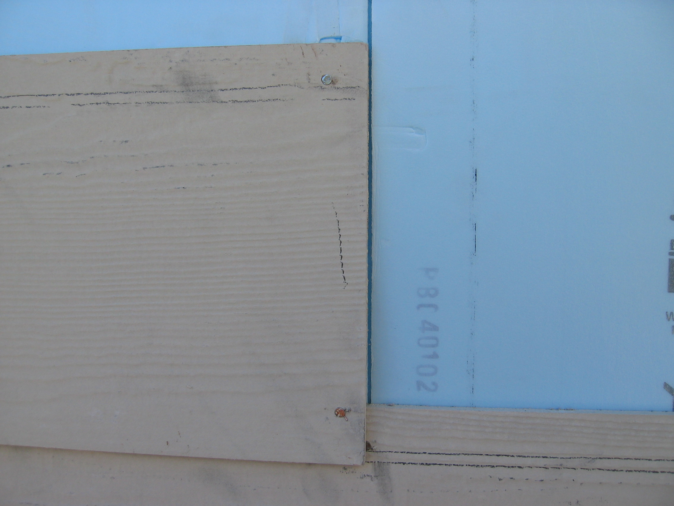
Right – Wood-to-sheathing joints are caulked so the sheathing can provide an air barrier for the home.
Image
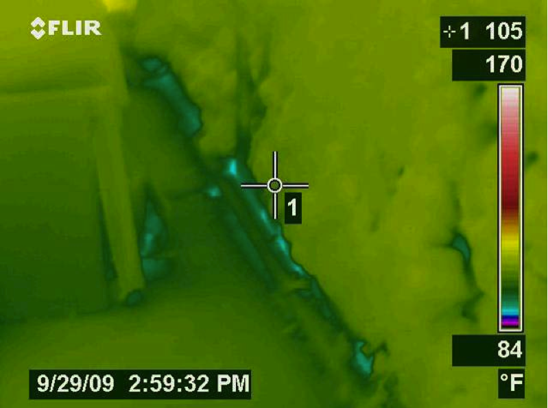
Right-- IR photo shows how effectively spray foam insulated/air sealed attic kneewall and the floor cavities under kneewall
Image

Image
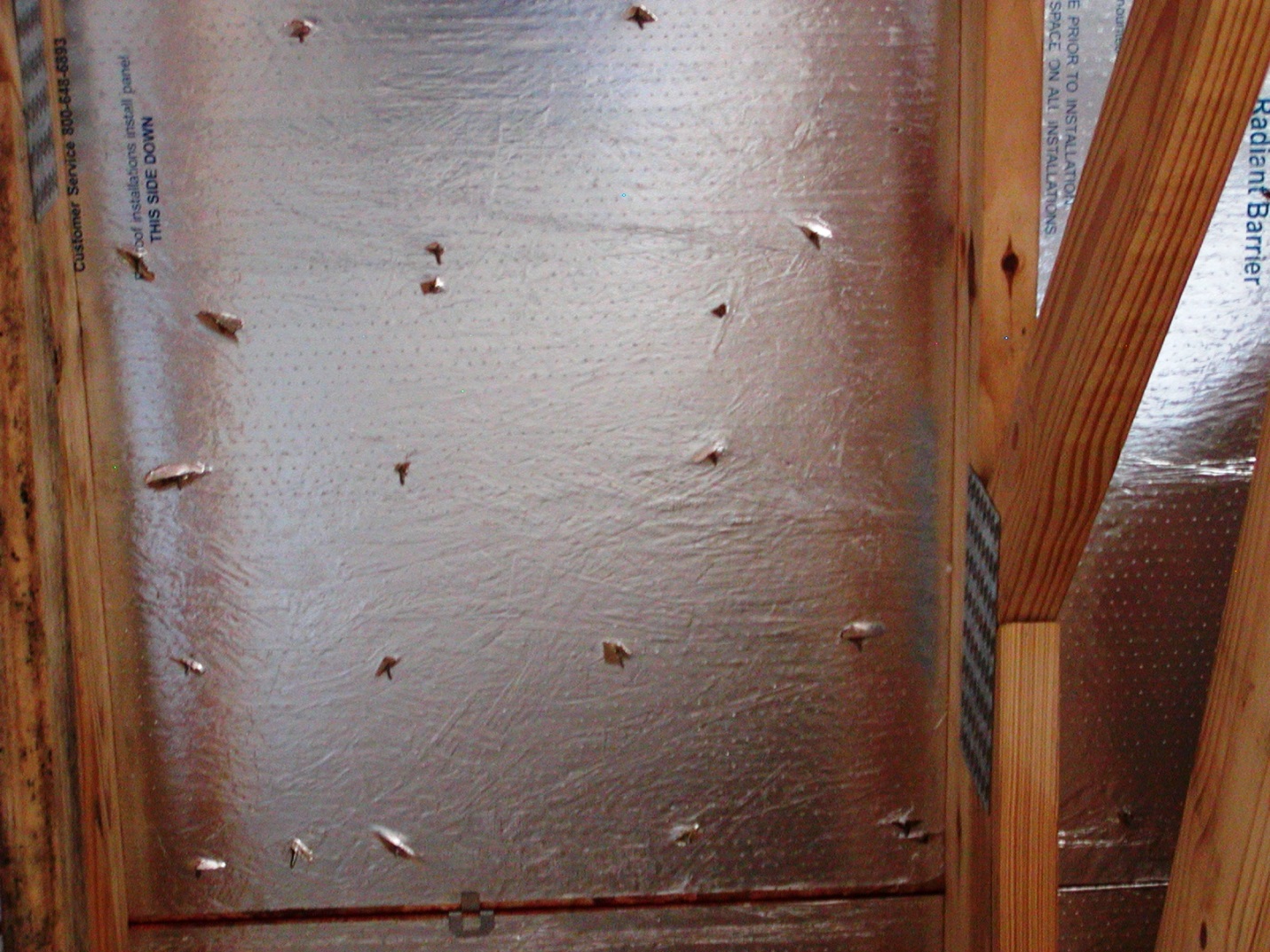
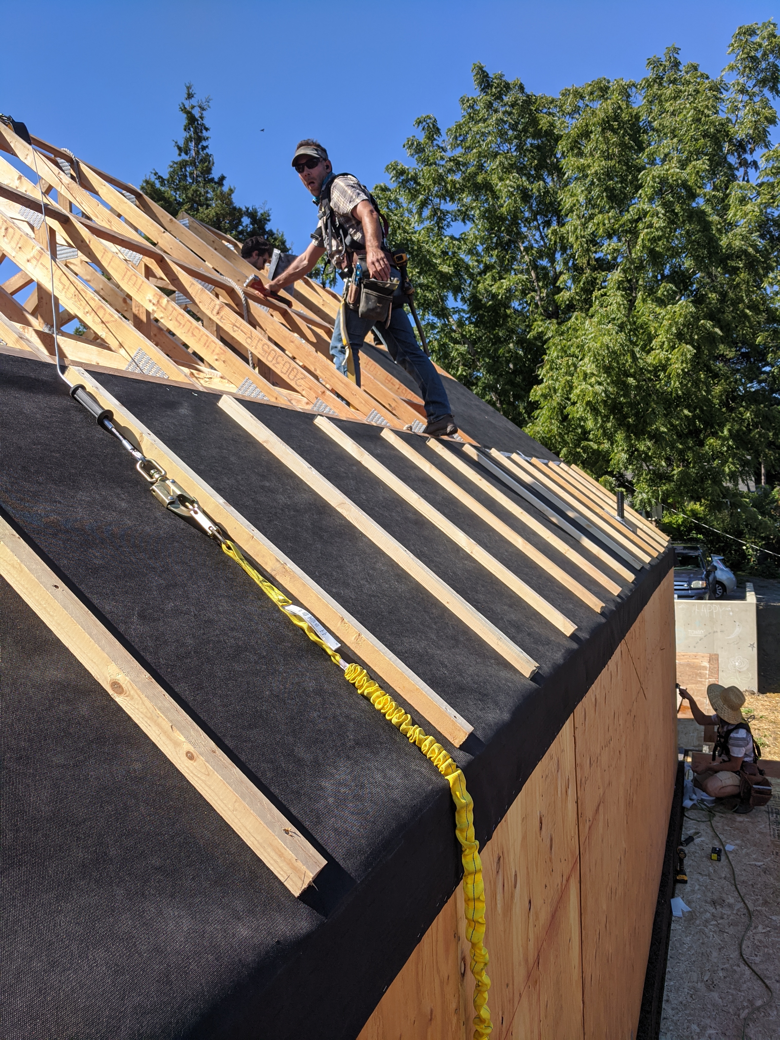
Roof decking has adhered radiant barrier that is perforated, in addition to the nail holes
Image
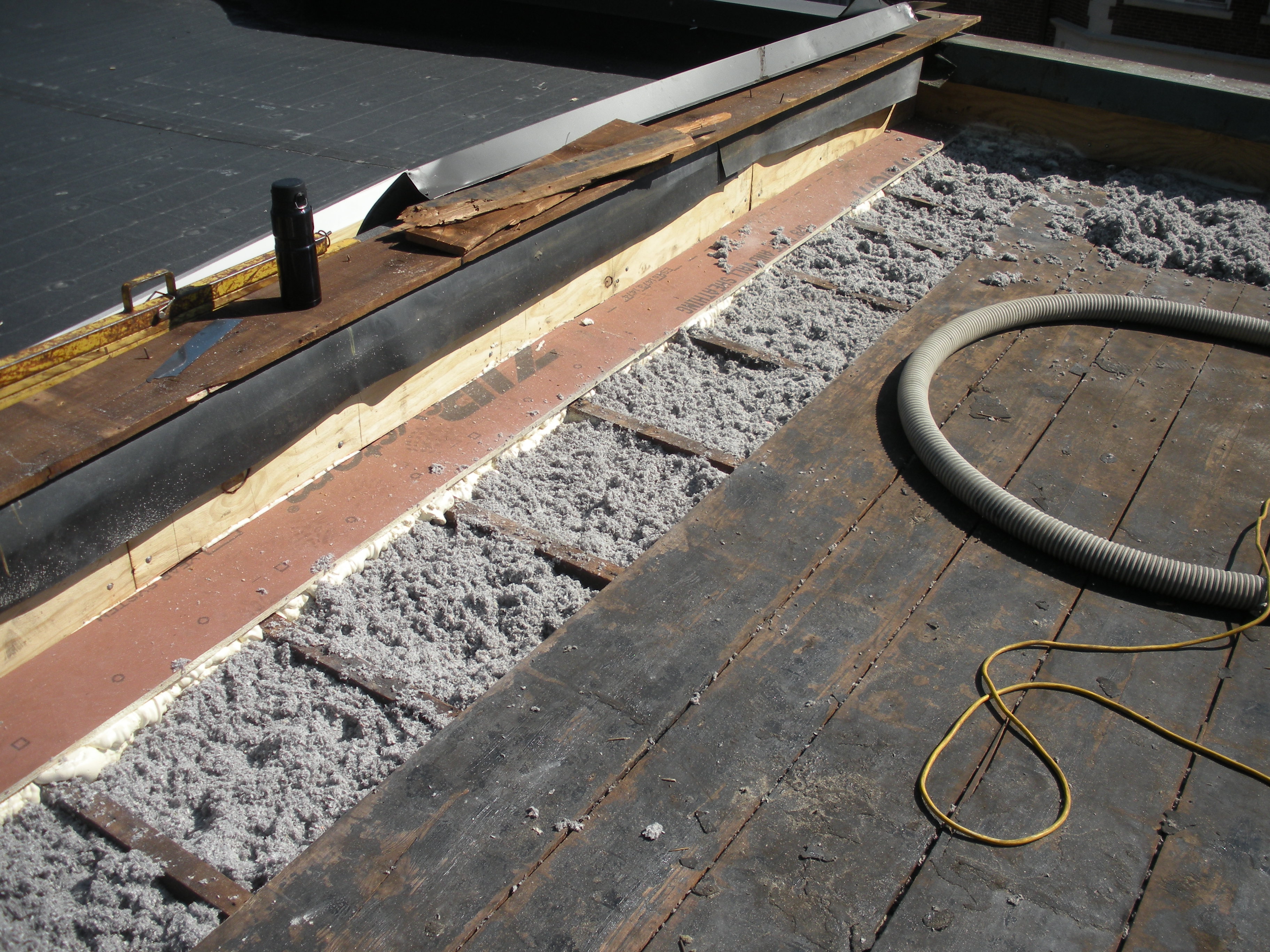
Roofing paper protects the top of the new plywood parapet while the base of the parapet is air sealed with spray foam and fibrous insulation is installed in the rafter cavities in this flat roof retrofit
Image
Stucco is installed over rigid insulation, which is installed over a drainage plane consisting of a drainage gap and building wrap layer over the sheathing
Image
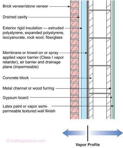
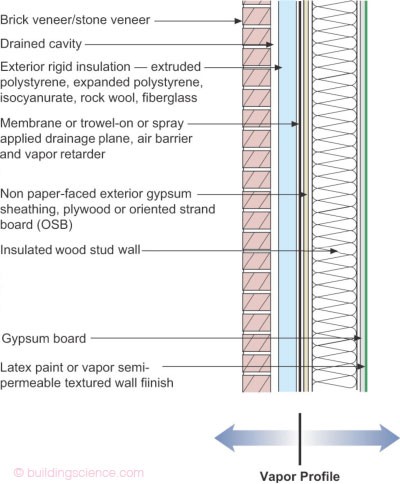
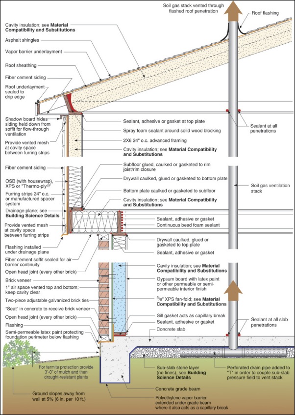
The “institutional” perfect wall works in all climate zones; water, air, vapor, and thermal control layers are exterior of the sheathing, assembly allows drying to interior and exterior
Image
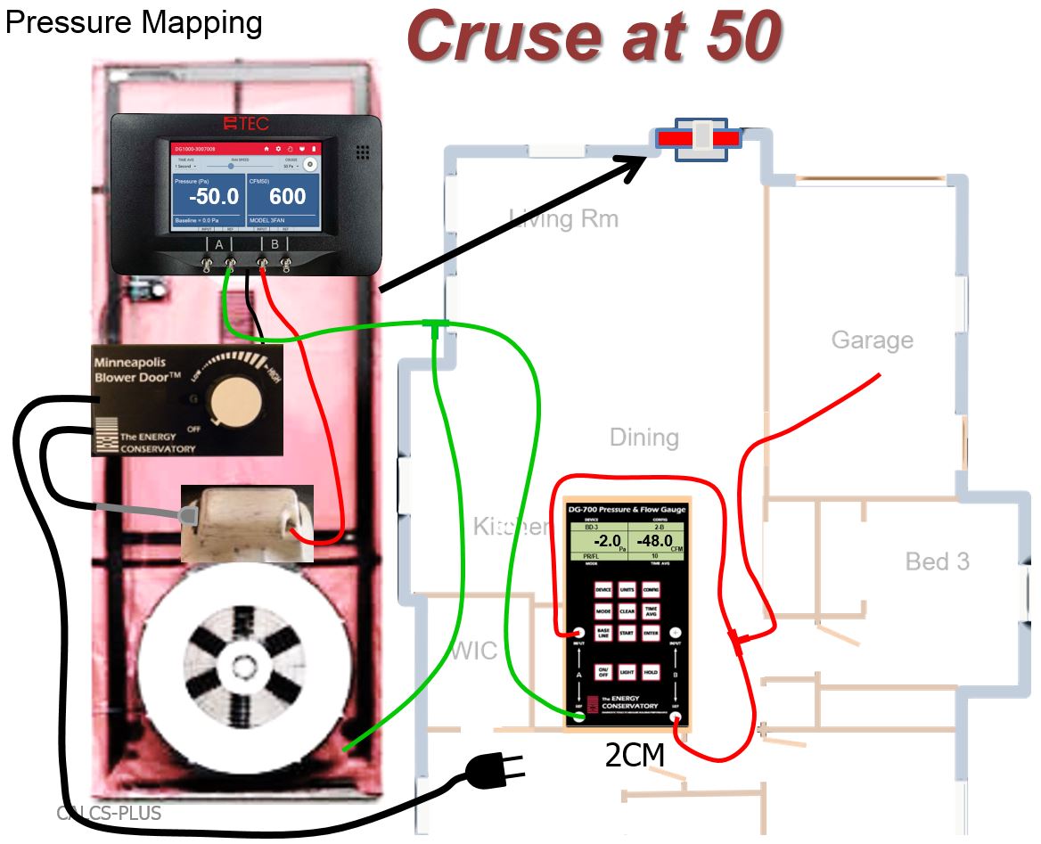
The air tightness of the garage-to-house air barrier can be tested with a blower door kit and two manometers
Image
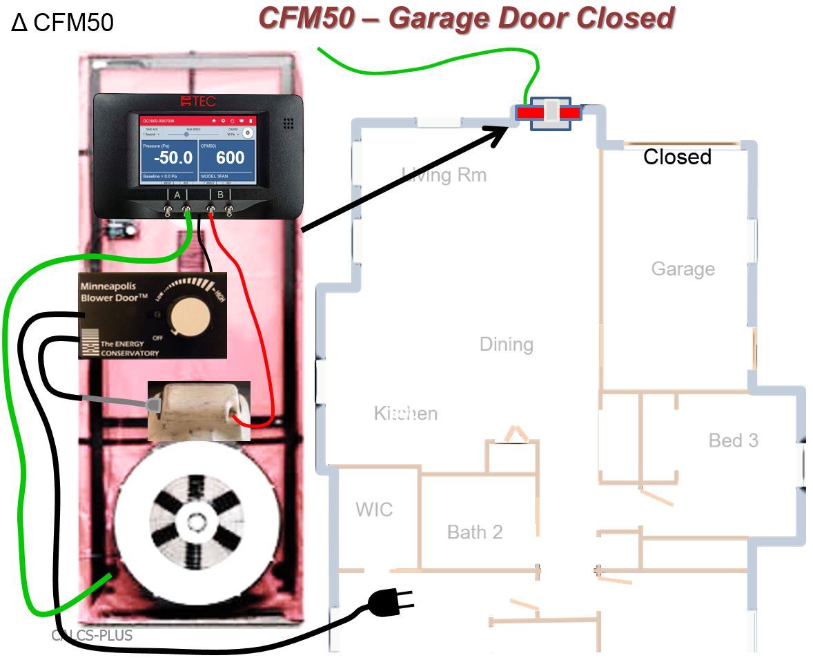
The air tightness of the house-garage air barrier can be tested using a CFM50 test that is first run with the garage door to outdoors closed
Image
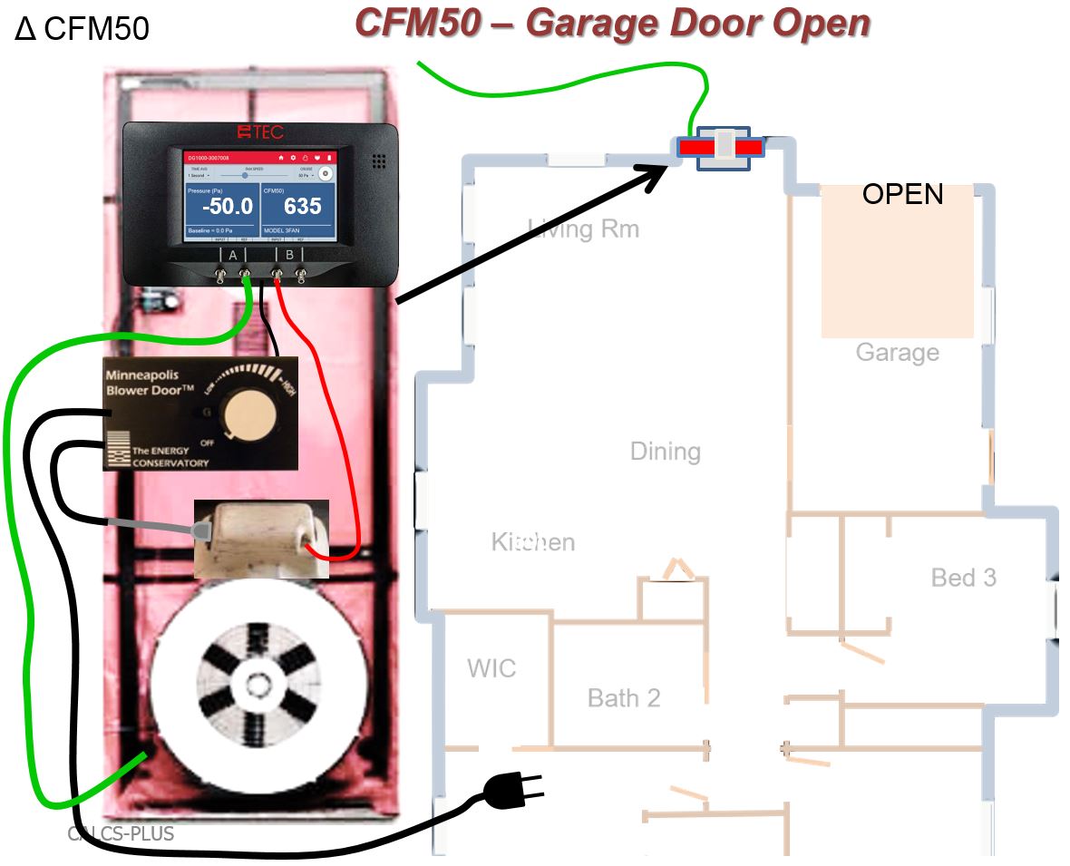
The air tightness of the house-garage air barrier can be tested using a CFM50 test that is run first with the garage door to outdoors closed and then with the overhead garage door to outdoors open
Image
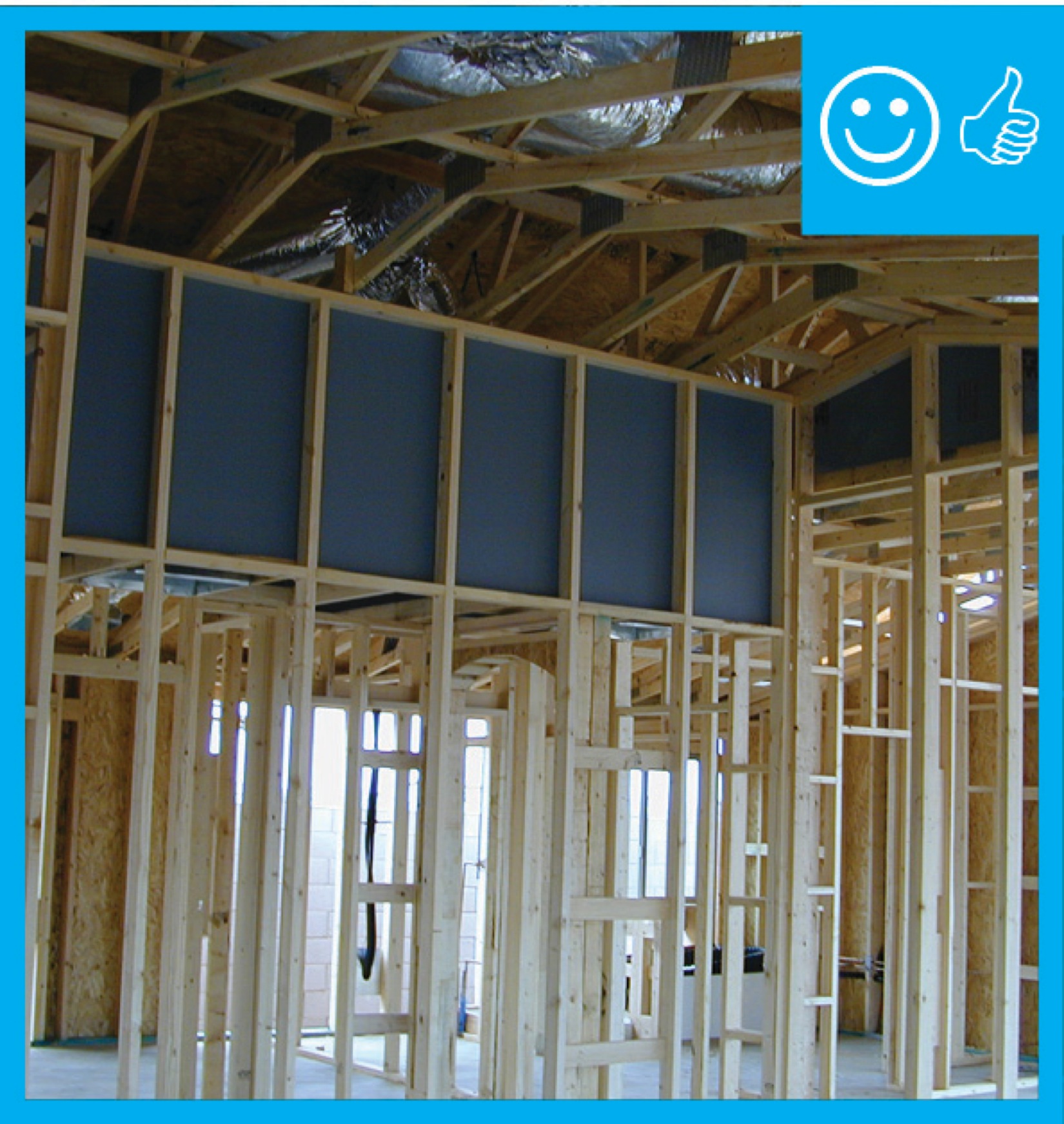
The attic knee walls were constructed from 2x6s and insulated with R-19 batt, backed with 1 inch of XPS foam board with taped joints to provide a solid air barrier over the insulated surfaces.
Image
The attic kneewall and the open floor cavities under kneewall are both sealed and insulated in one step with spray foam insulation
Image
The base of the plywood parapet is air sealed with spray foam and fibrous insulation is installed in the rafter cavities in this flat roof retrofit
Image
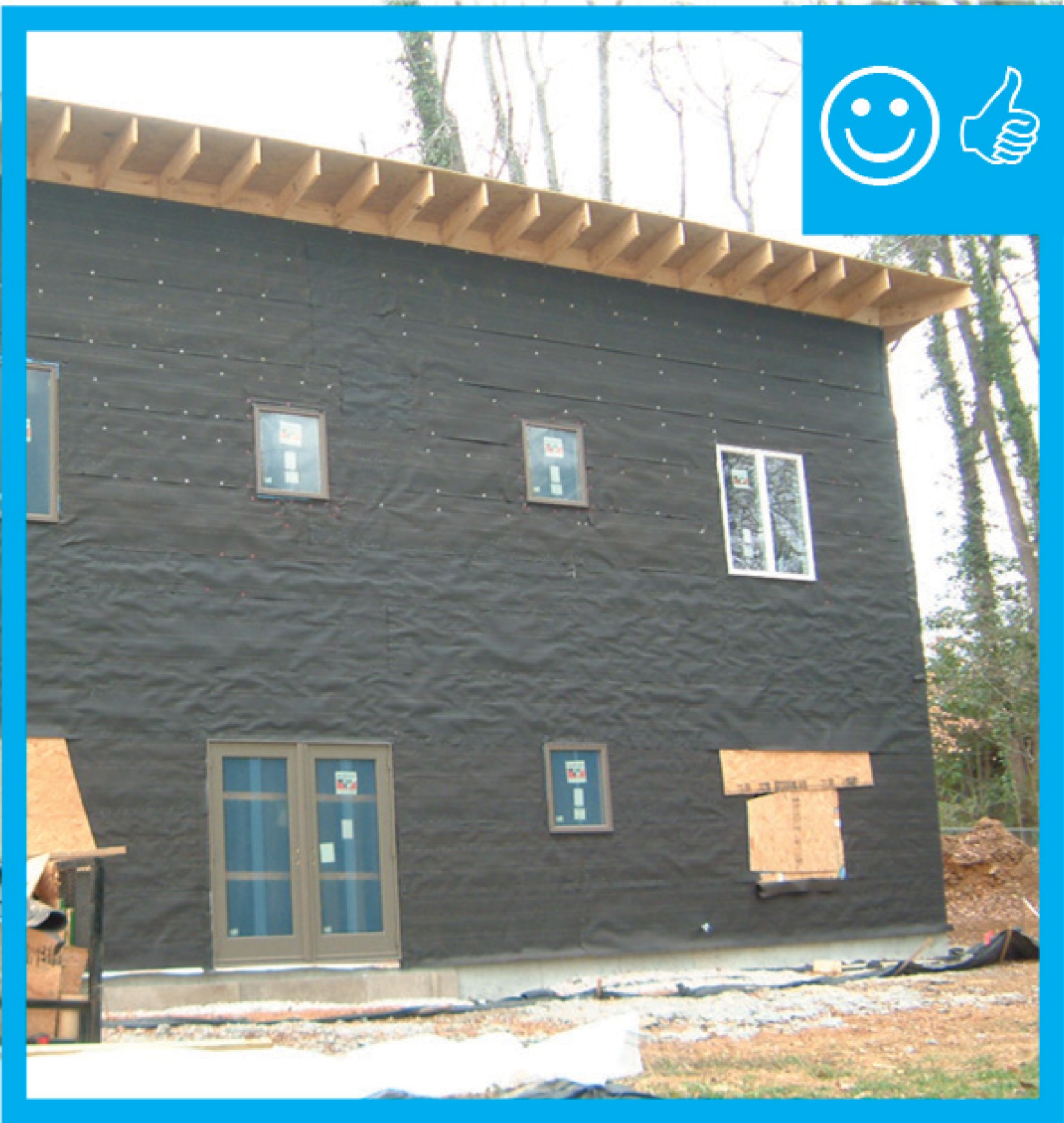
The black coating on these walls is a liquid-applied asphalt-based air and moisture barrier.
Image
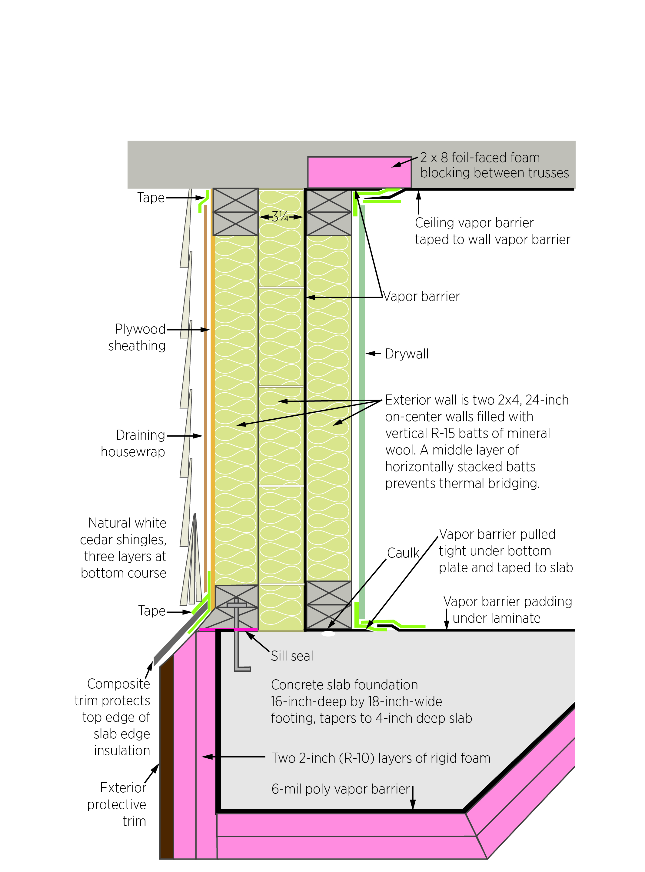
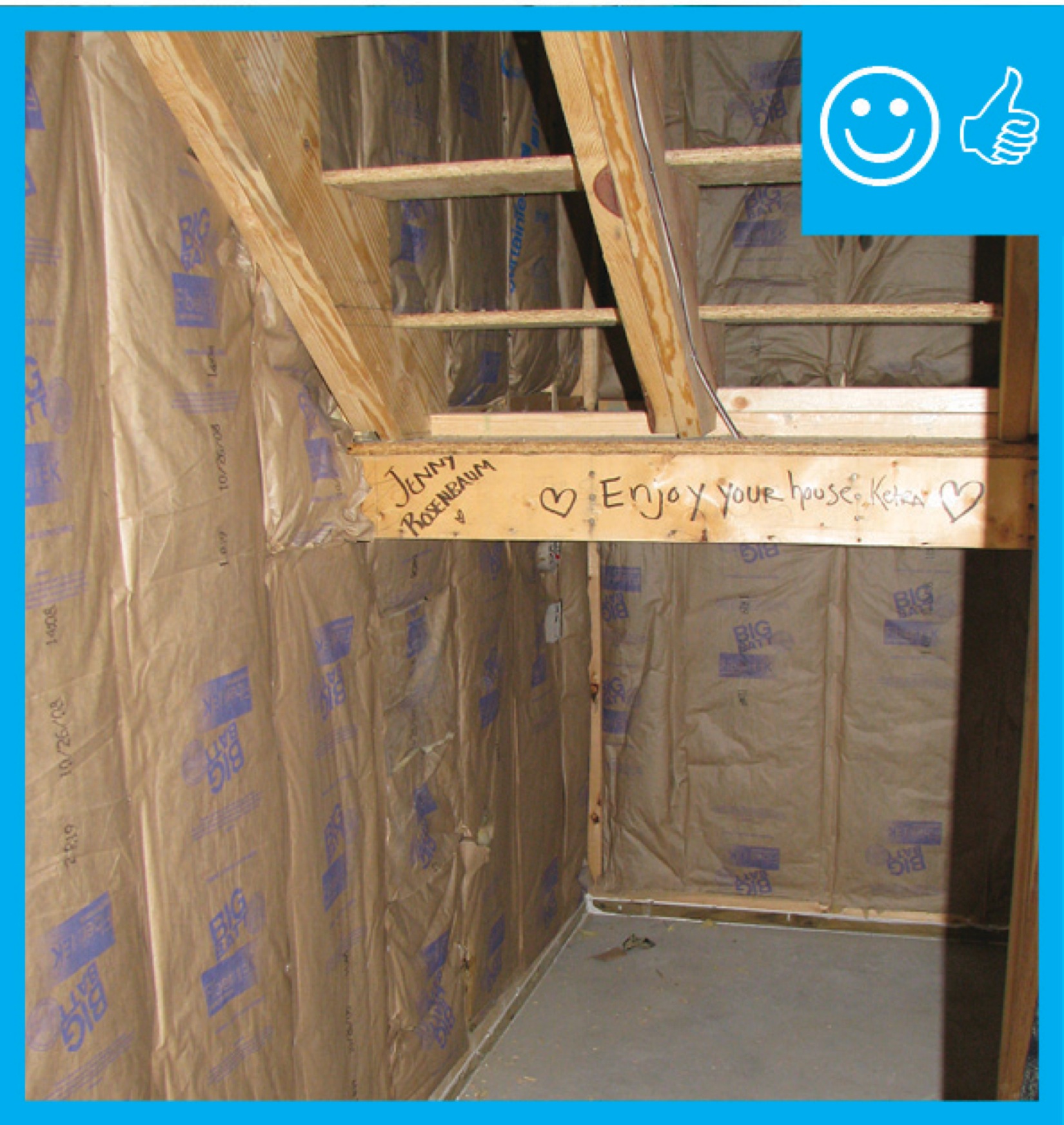
The builder in this very cold climate installed three layers of unfaced mineral wool batt in the double wall with a code-required vapor barrier between the middle and inner layers of wall insulation that is taped to barriers in the ceiling and floor.
Image
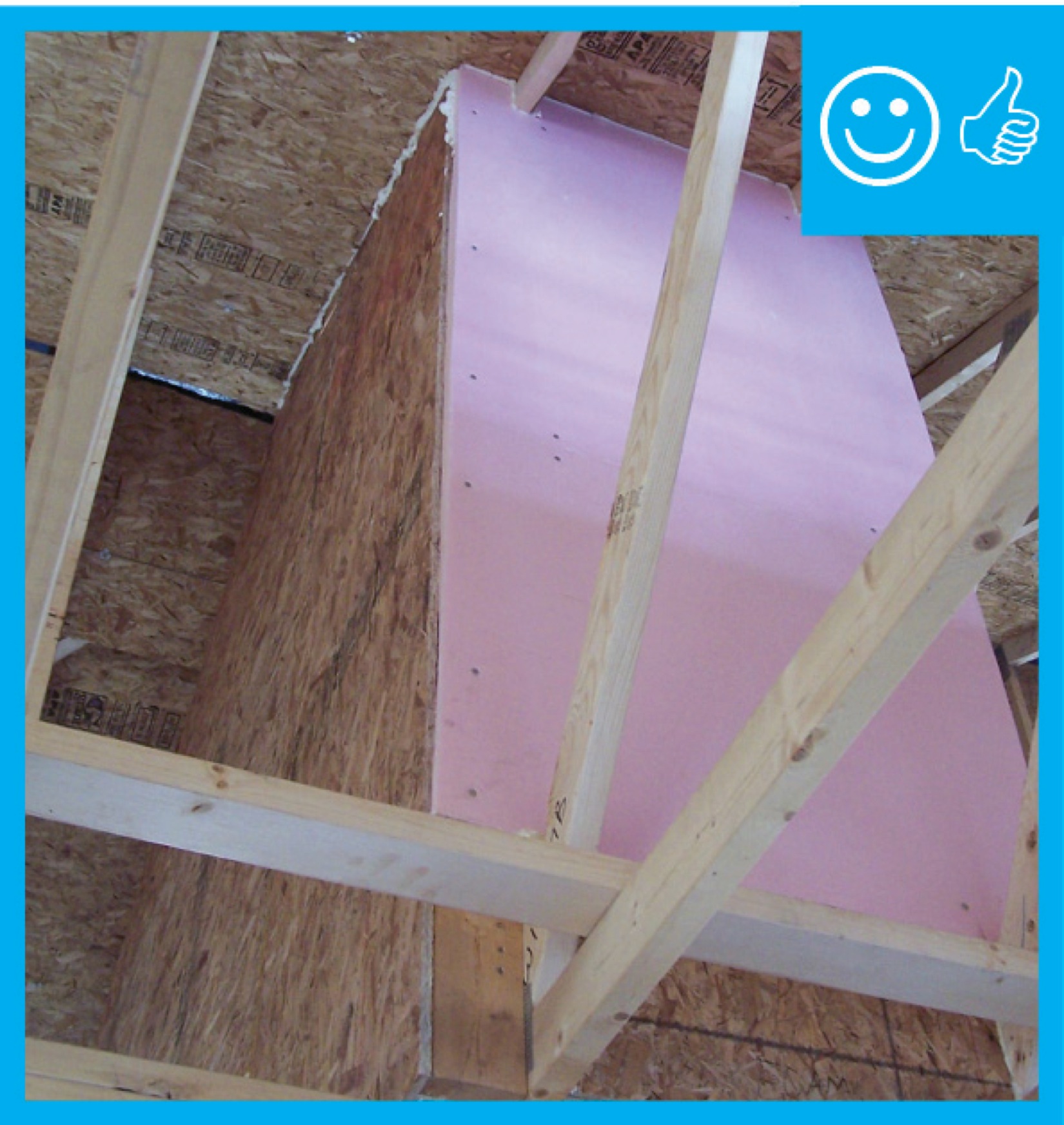
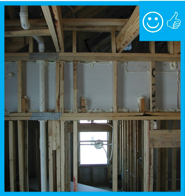
The drywall above the chase extends beyond adjoining top plates for a continuous air barrier
Image
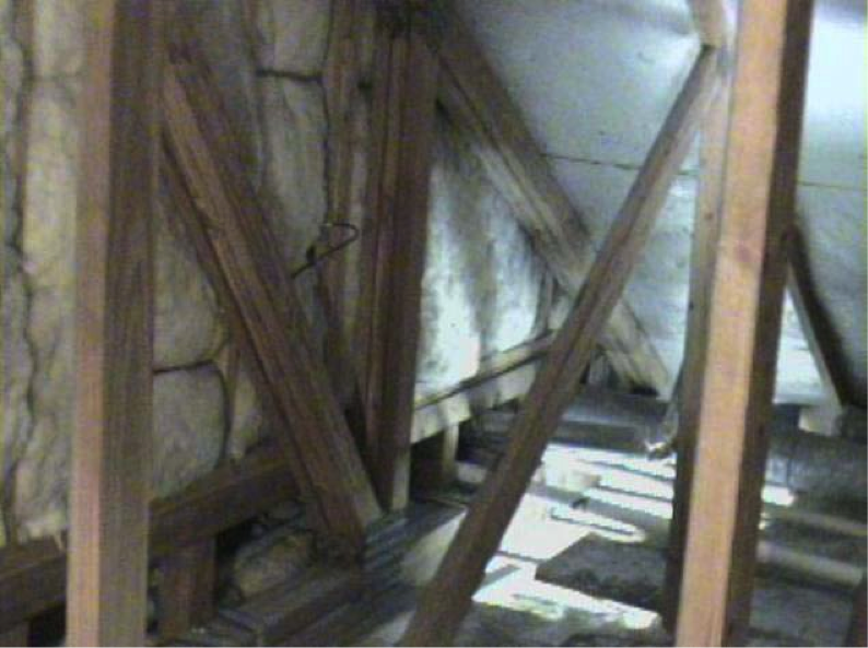
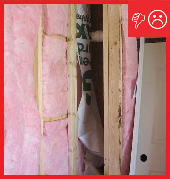
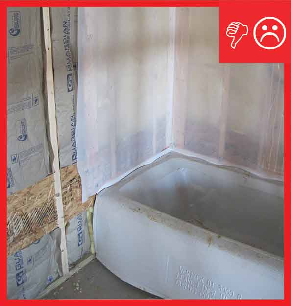
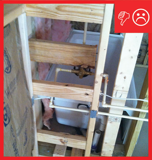
The floor cavities under this attic kneewall are completely open to the unconditioned attic space and a prime target for wind washing
Image

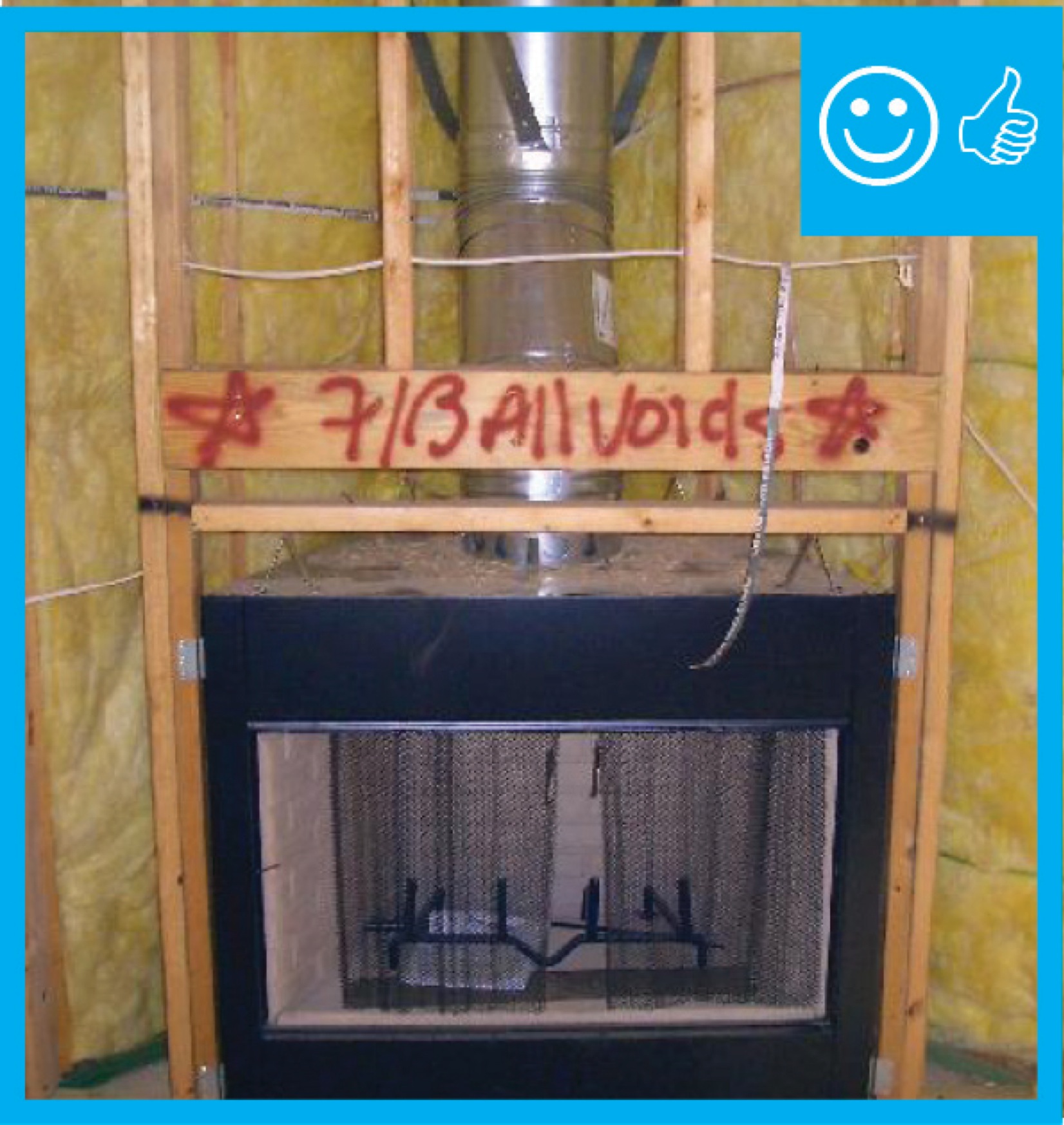
The foil-faced insulation behind this fireplace provides an air barrier and thermal shield.
Image
The home is sheathed with rigid foam insulation and all seams and holes are taped to provide a continuous air barrier.
Image
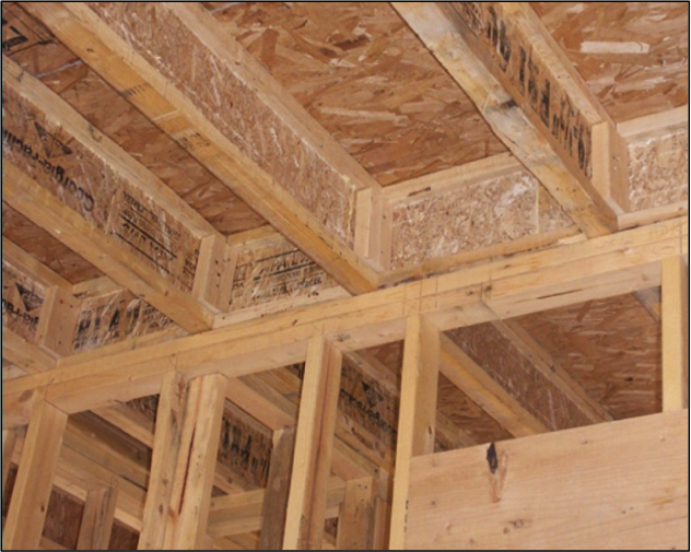
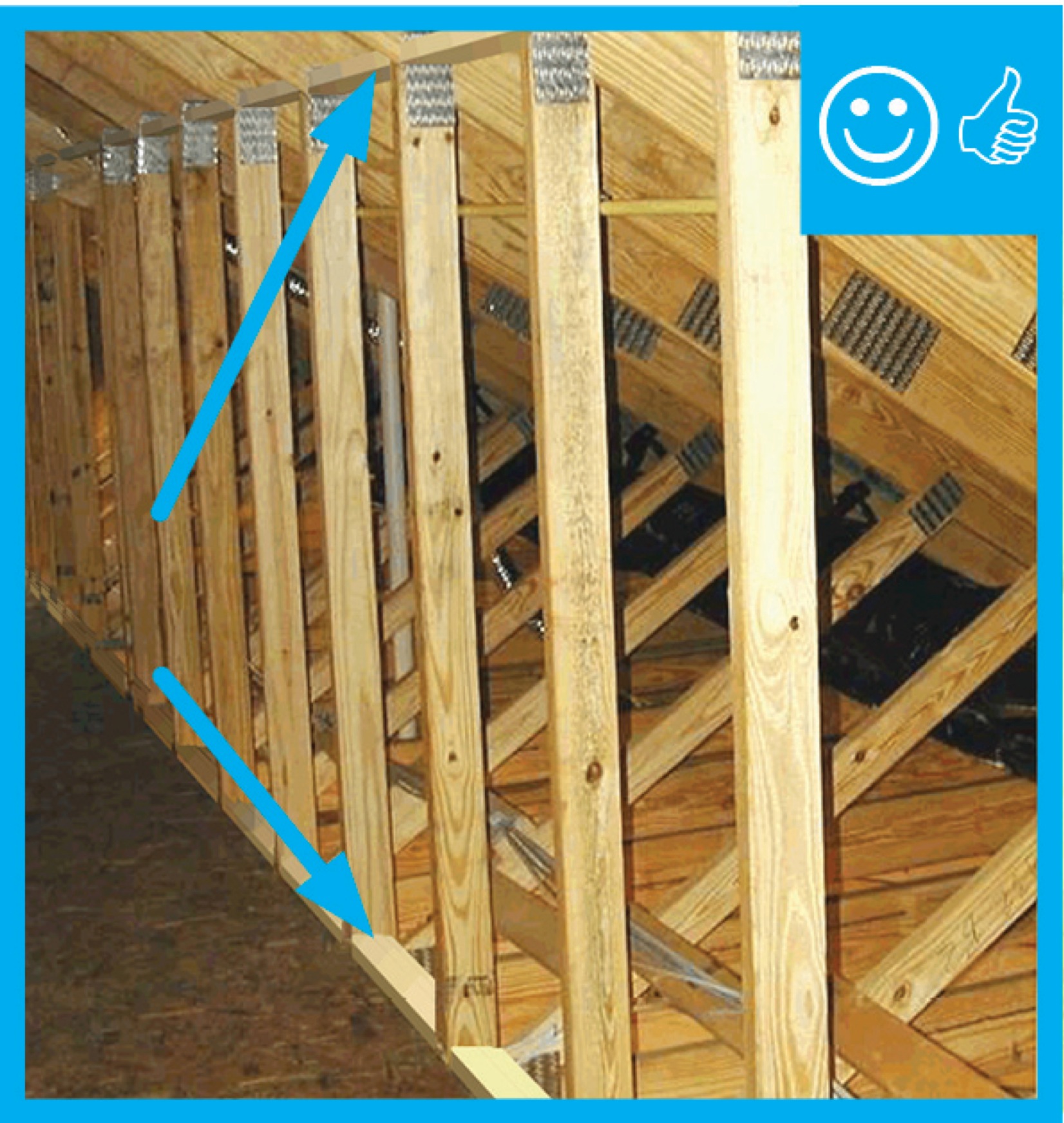
The I-joist is continuous along the shared wall and serves as a natural air barrier between the garage and the house
Image
Image
Image
Image
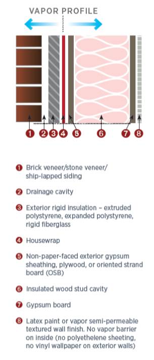
The Perfect Wall includes water, air, thermal, and vapor layers with continuous insulation exterior of the sheathing to reduce the condensation potential in the wall.
Image
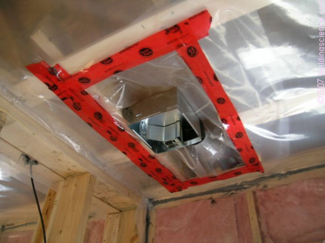
The polyethylene ceiling vapor barrier is sealed to form an air barrier around the exhaust fan in this very cold climate location (≥ CZ 6).
Image
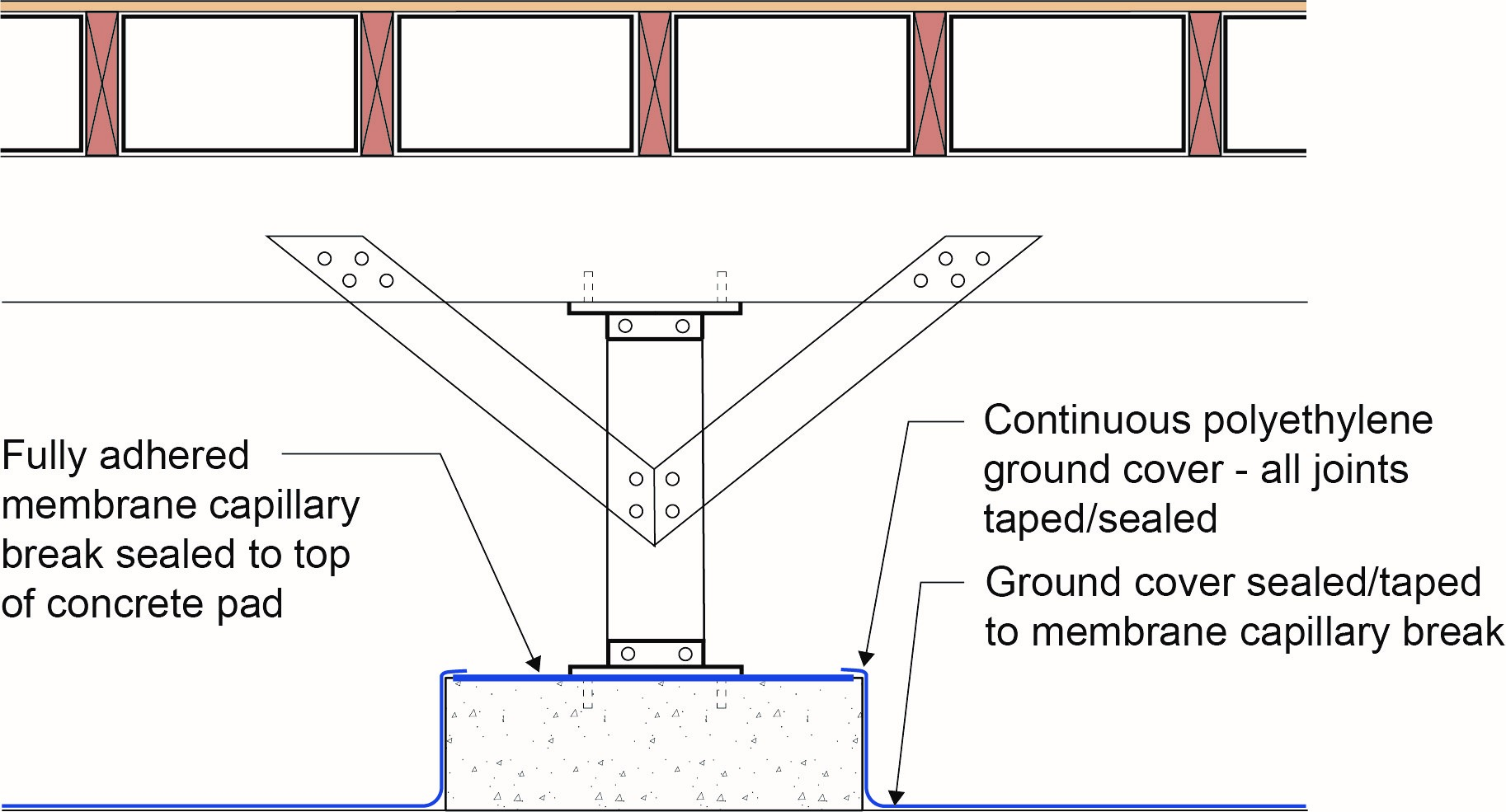
The polyethylene ground cover in the crawl space is lapped up sides of piers to posts to provide a continuous air and vapor barrier
Image
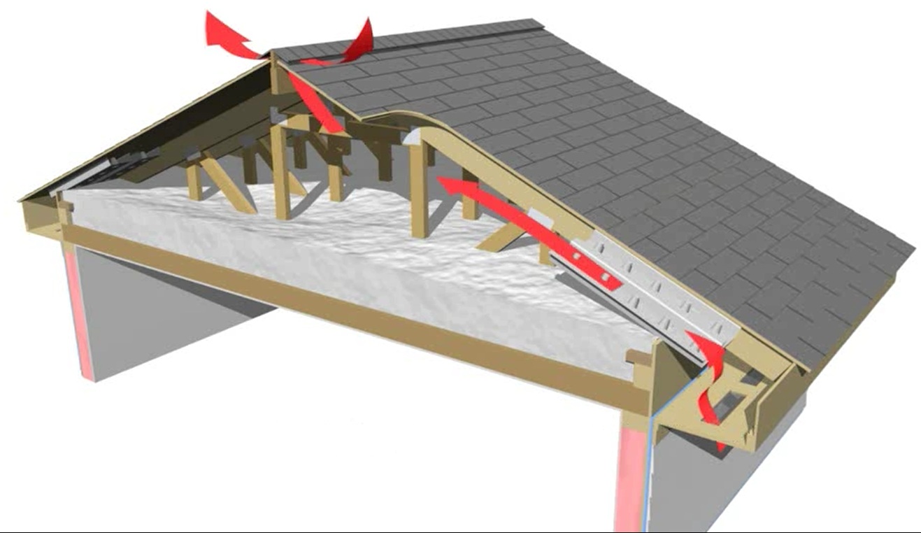
The soffit dam and baffle allow air to flow through the vents without disturbing the insulation covering the top plates
Image
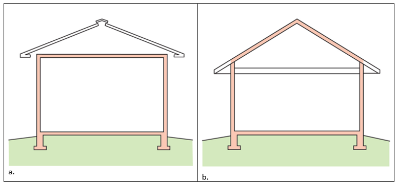
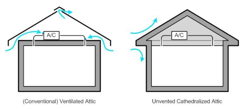
The thermal boundary for a gable roof can be located at either a) the flat ceiling with a vented attic or b) the roof line for an unvented attic
Image
The wall behind the fireplace is an exterior wall and requires a thermal barrier that is continuous with the rest of the wall’s insulation
Image
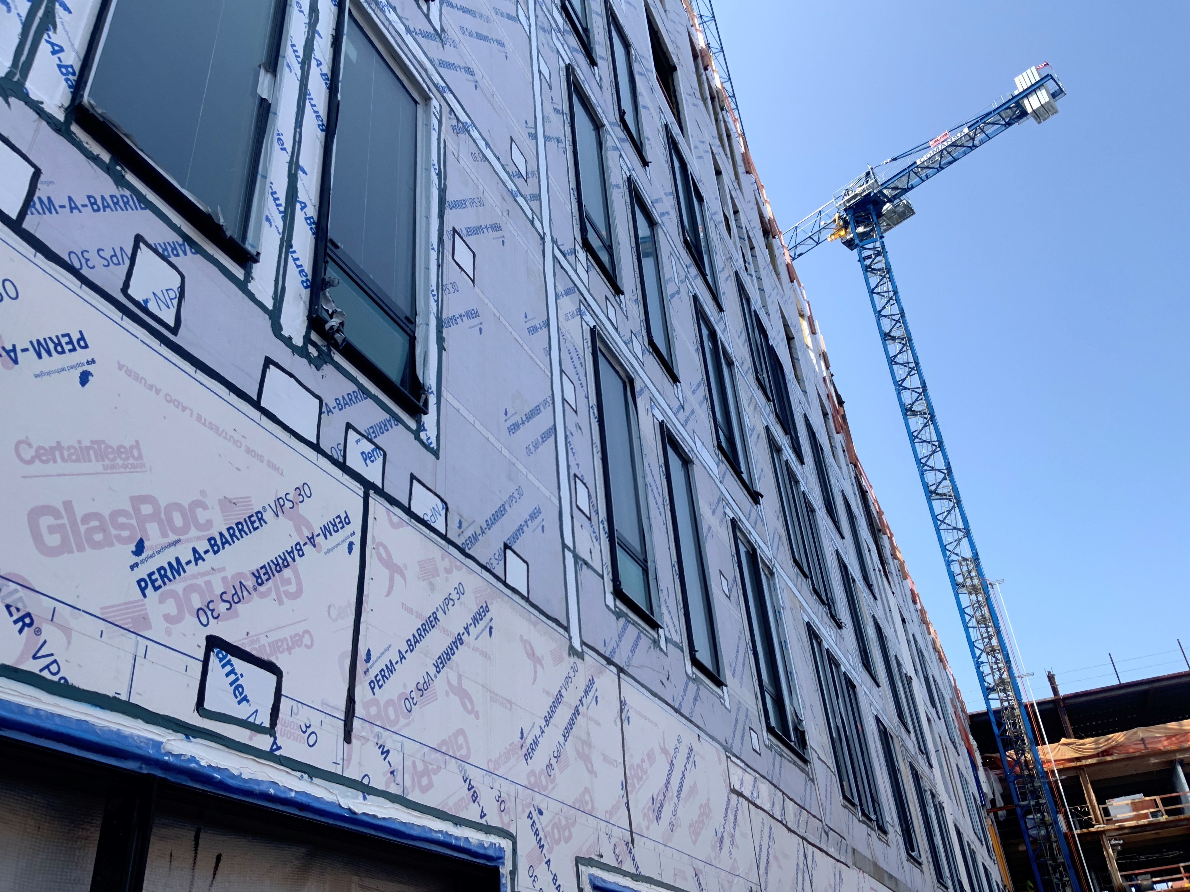
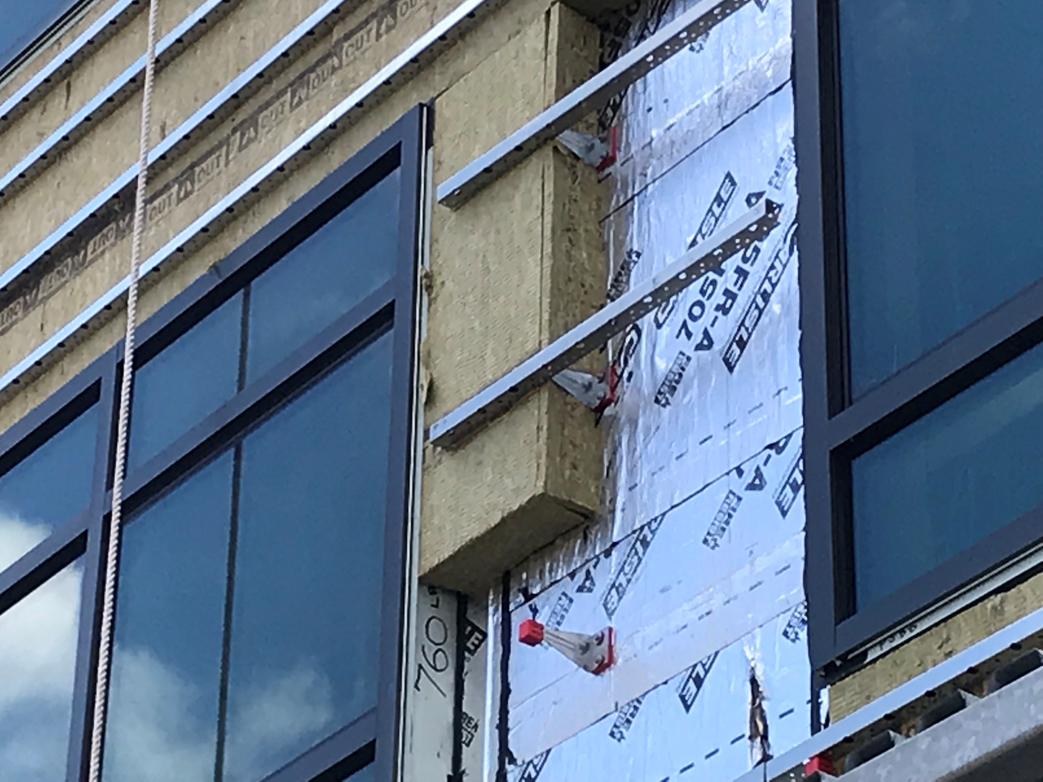
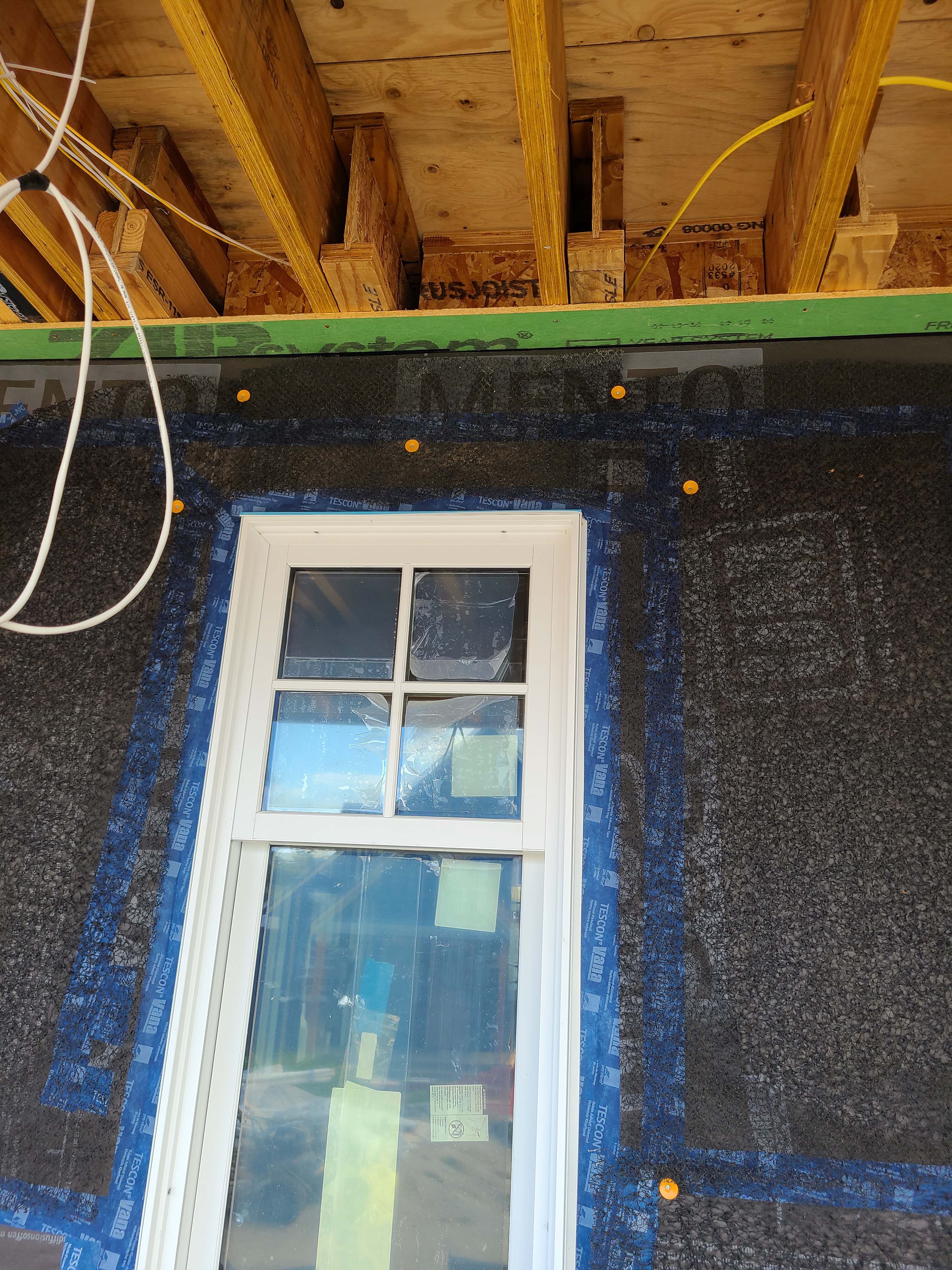
The windows in this building are connected to the fully adhered water and air control layer using fluid-applied flashing
Image
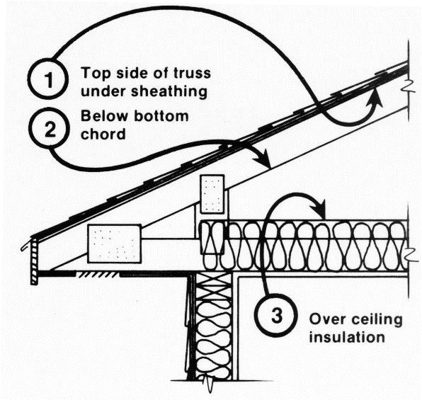
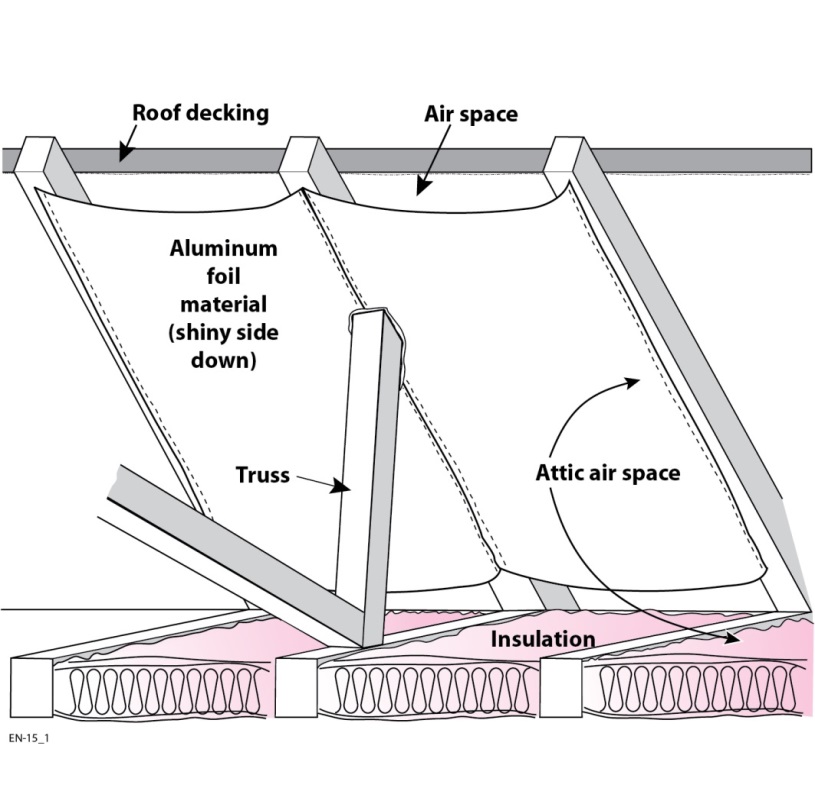
There are three potential locations for an attic radiant barrier – adhered to the underside of the roof decking, hanging from the rafters, or on the ceiling insulation
Image
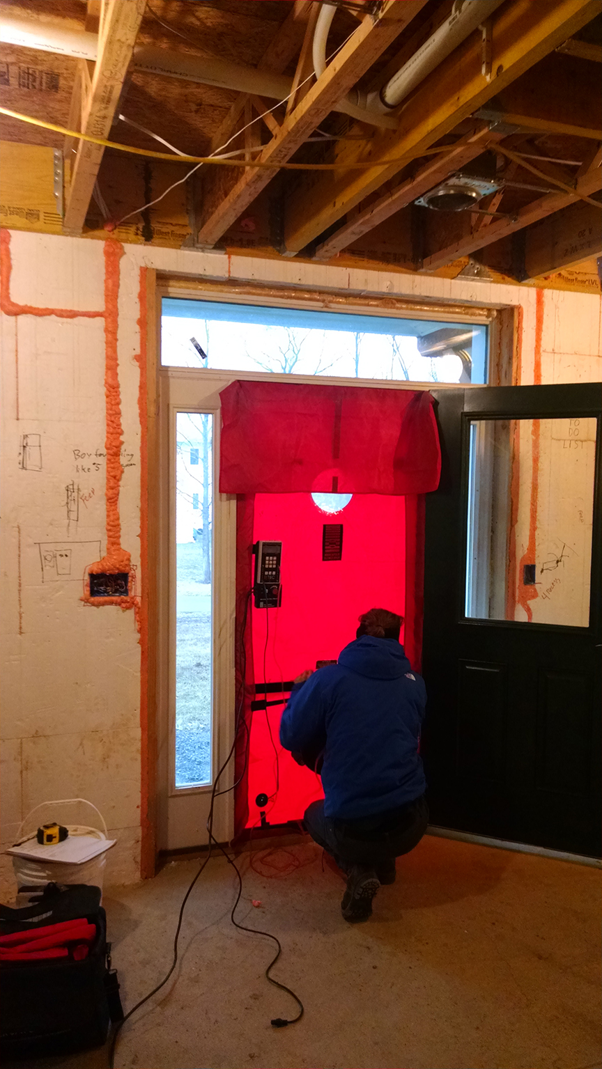
These ICF homes are blower door tested during construction, before the drywall is installed, when air leaks can be easily sealed.
Image
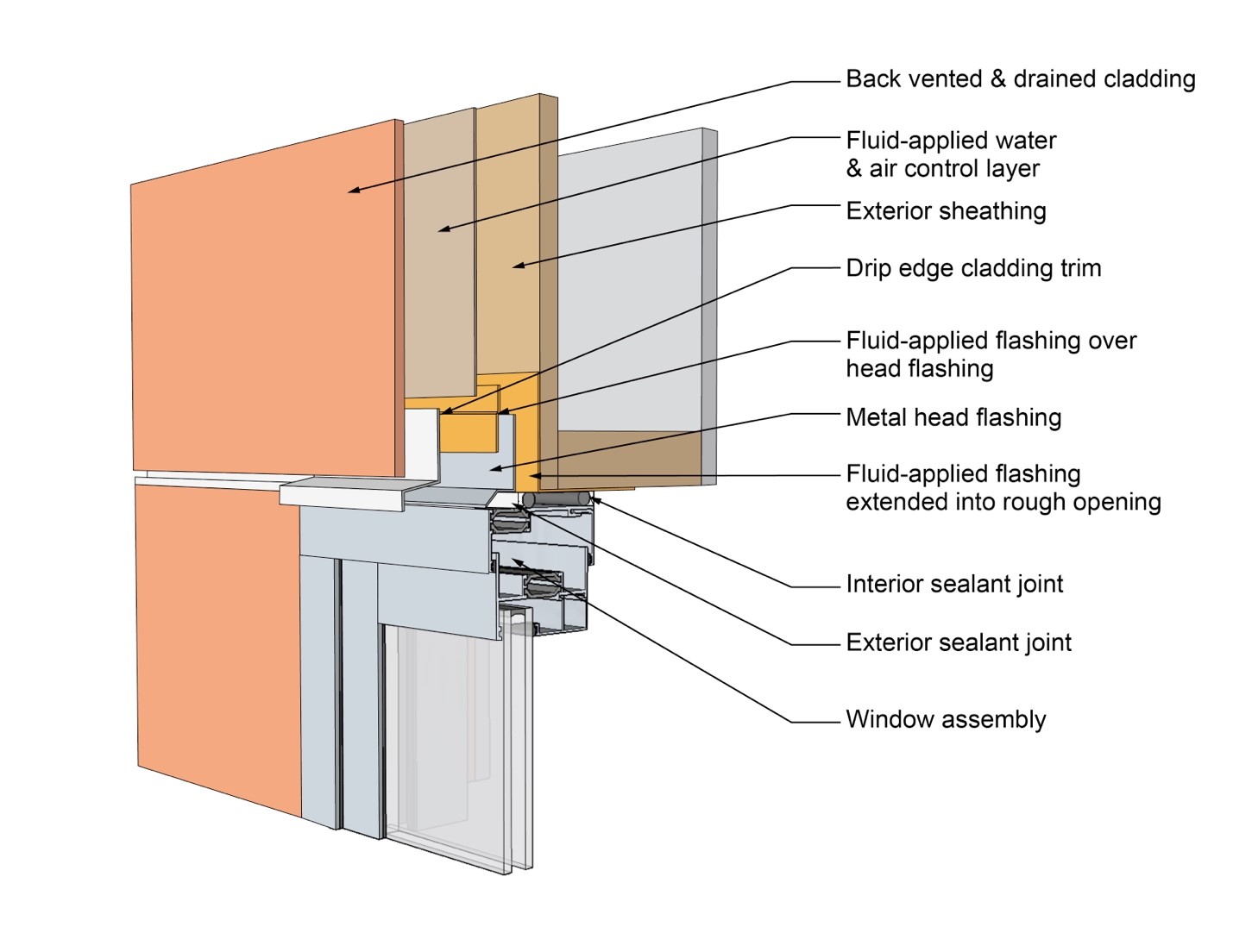
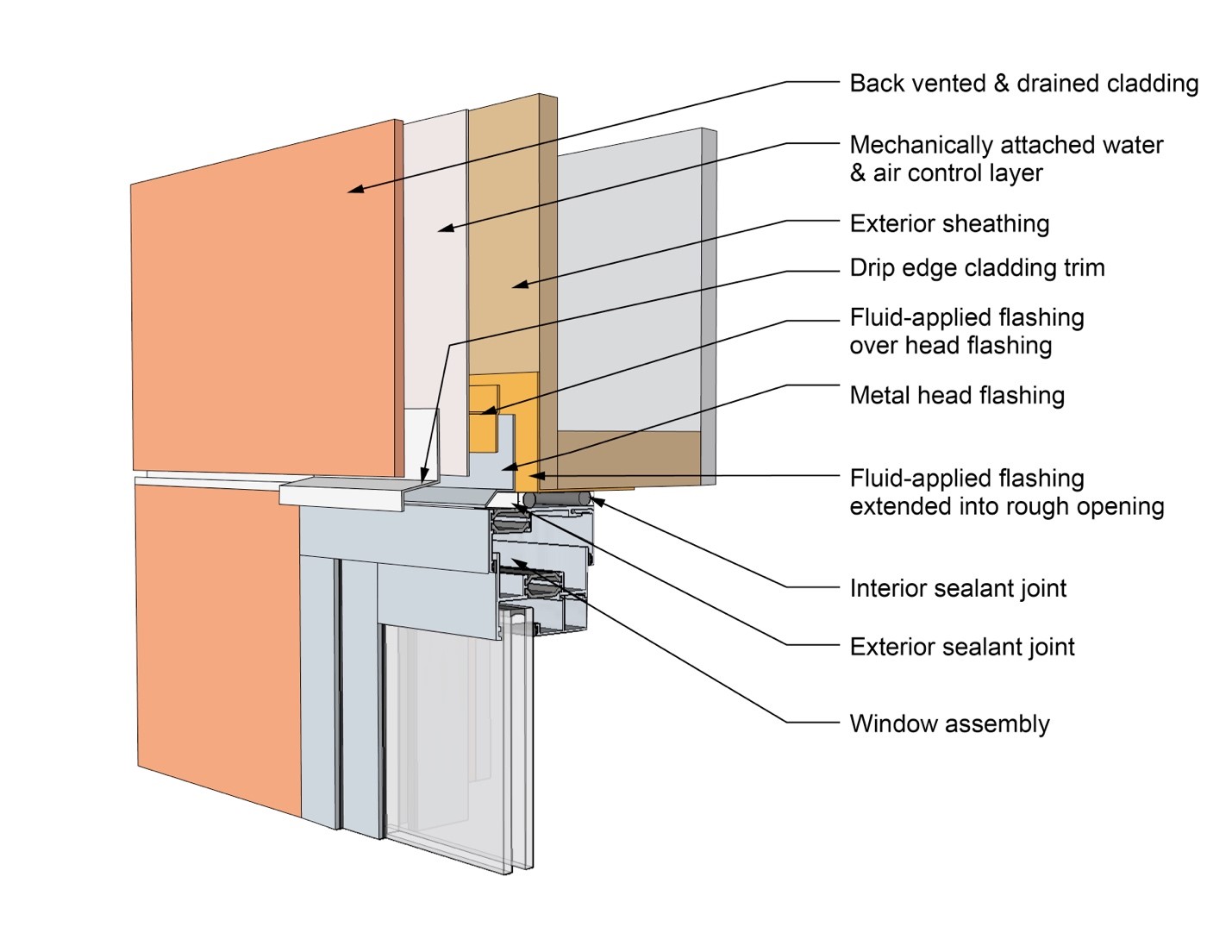
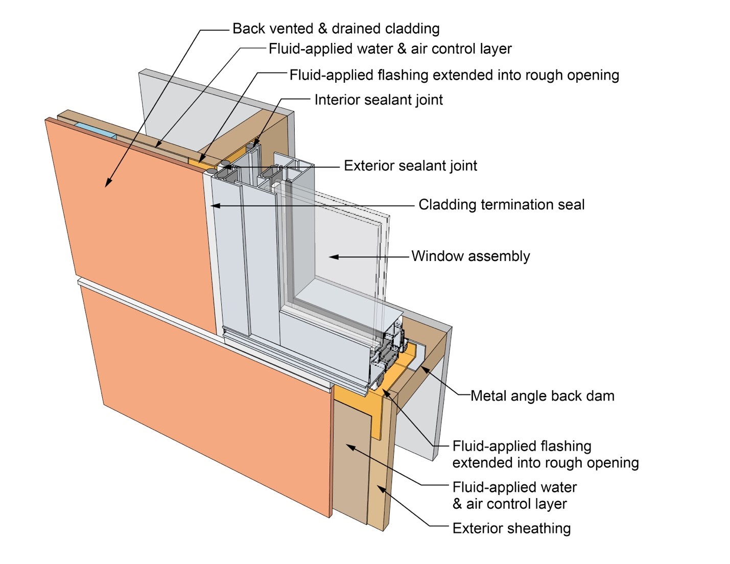
This drawing shows key head details for a window installation using a fluid-applied flashing on a wall with a fluid-applied water and air control layer
Image
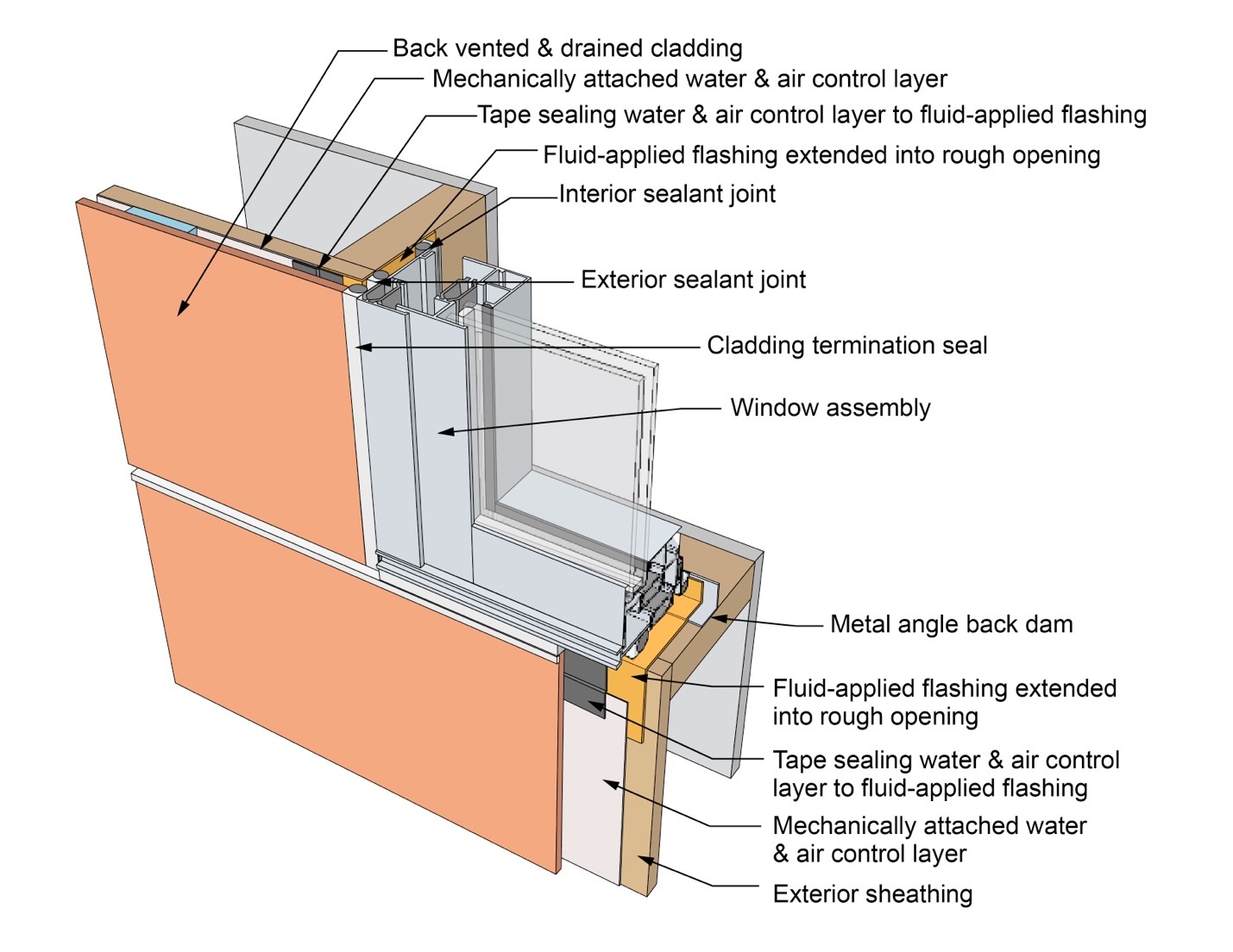
This drawing shows key head details for a window installation using a fluid-applied flashing on a wall with a mechanically attached water and air control layer
Image
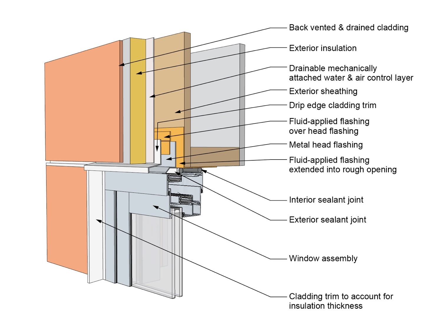
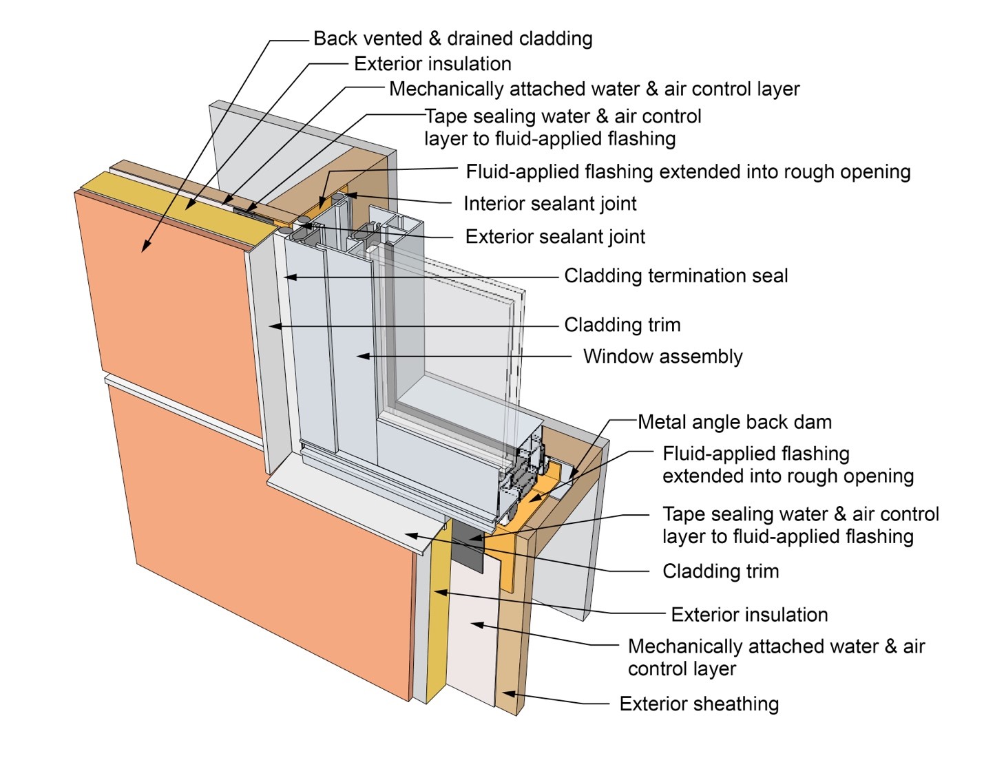
This drawing shows key head details for a window installation using a fluid-applied flashing on a wall with a mechanically attached water and air control layer and continuous insulation
Image
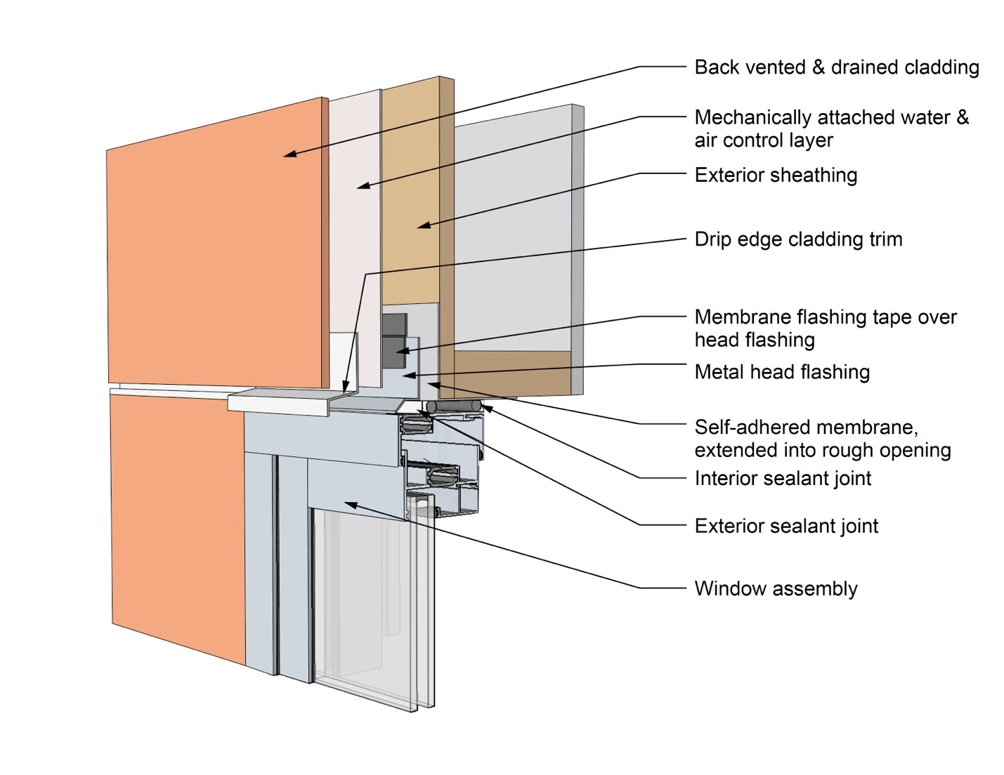
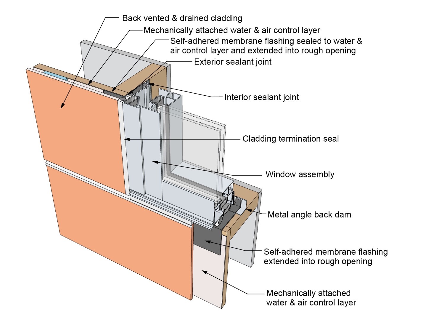
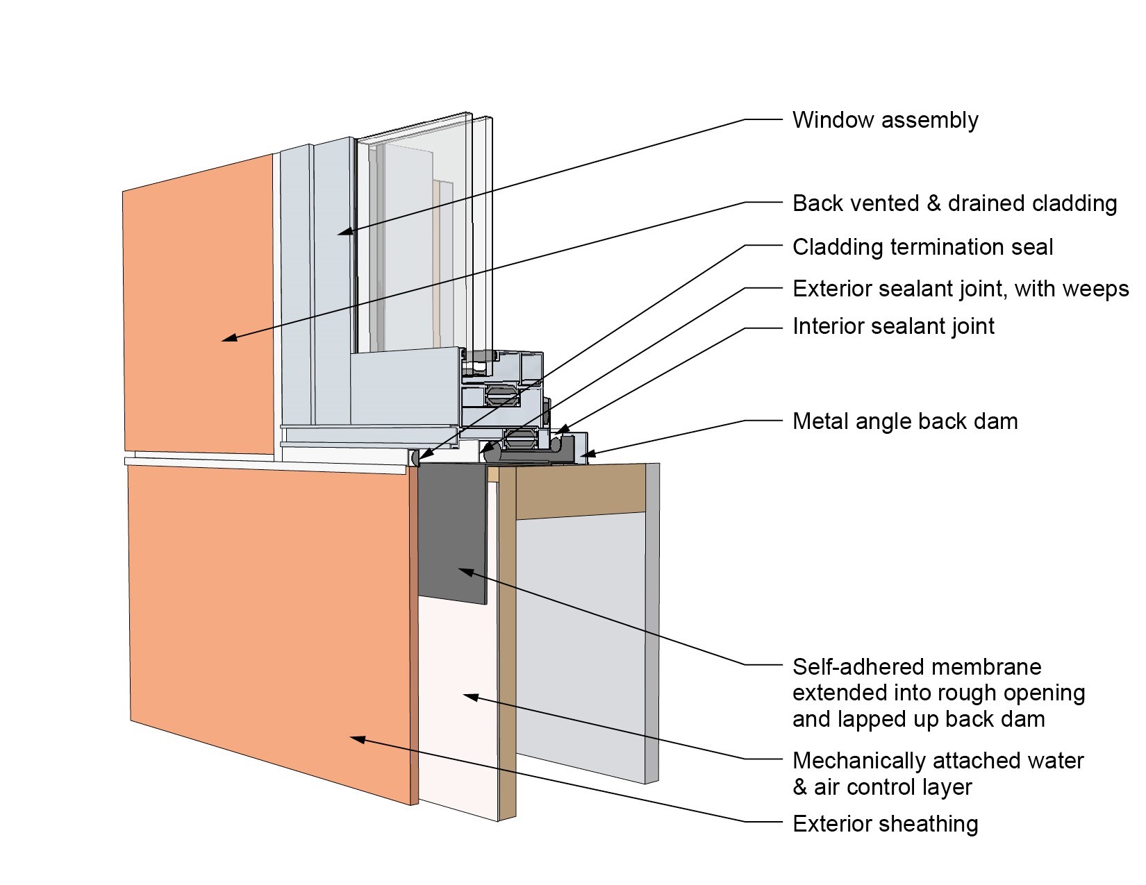
This drawing shows key head details for a window installation using a self-adhered membrane tape flashing on a wall with a mechanically attached water and air control layer
Image
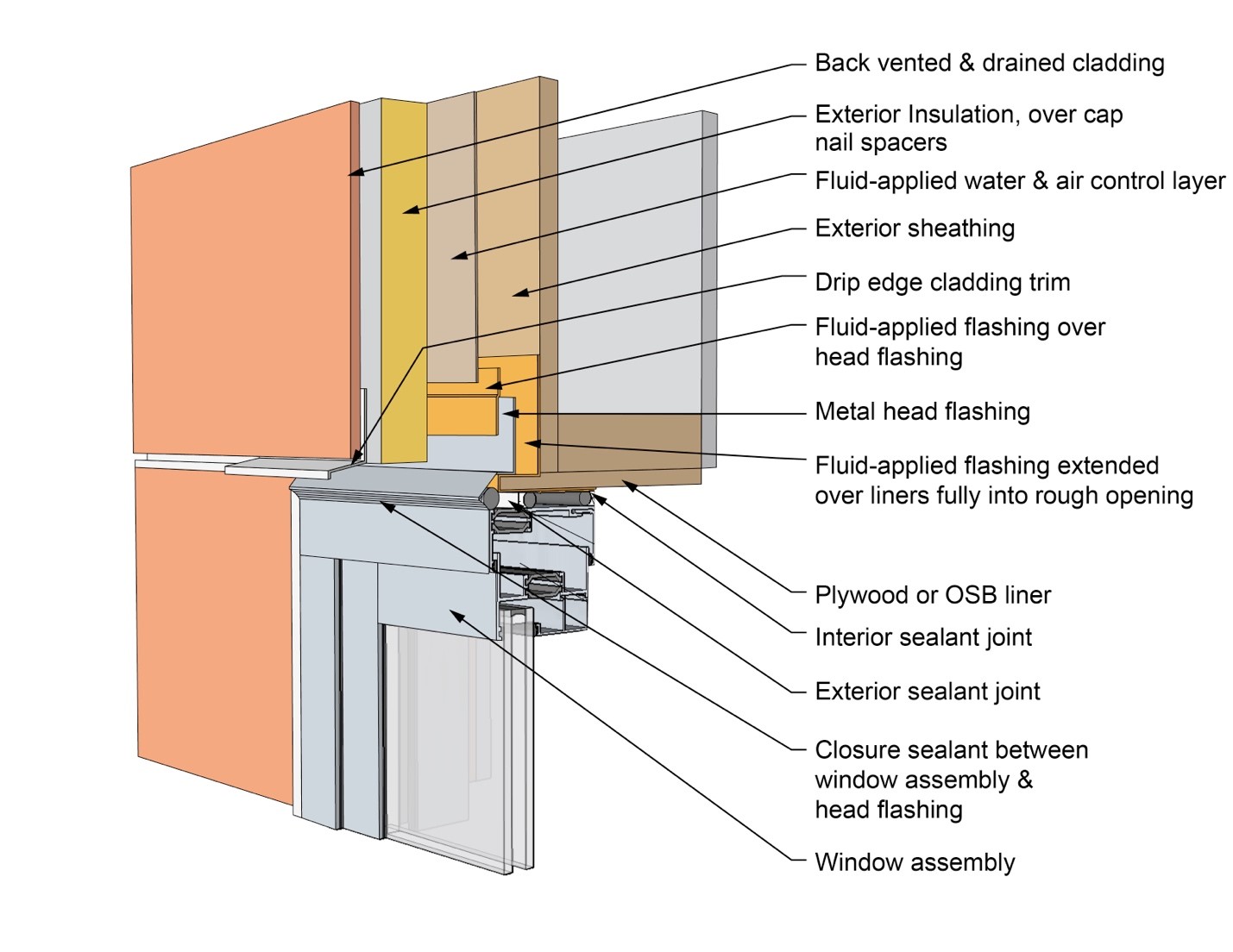
This drawing shows key head details for an “outie” window installation using a fluid-applied flashing on a wall with a fluid-applied water and air control layer and continuous insulation
Image
This drawing shows key jamb details for a window installation using a fluid-applied flashing on a wall with a fluid-applied water and air control layer
Image
This drawing shows key jamb details for a window installation using a fluid-applied flashing on a wall with a mechanically attached water and air control layer
Image
This drawing shows key jamb details for a window installation using a fluid-applied flashing on a wall with a mechanically attached water and air control layer and continuous insulation
Image
This drawing shows key jamb details for a window installation using a self-adhered membrane tape flashing on a wall with a mechanically attached water and air control layer
Image
This drawing shows key jamb details for an “outie” window installation using a fluid-applied flashing on a wall with a fluid-applied water and air control layer and continuous insulation
Image
This drawing shows key sill details for a window installation using a fluid-applied flashing on a wall with a fluid-applied water and air control layer
Image
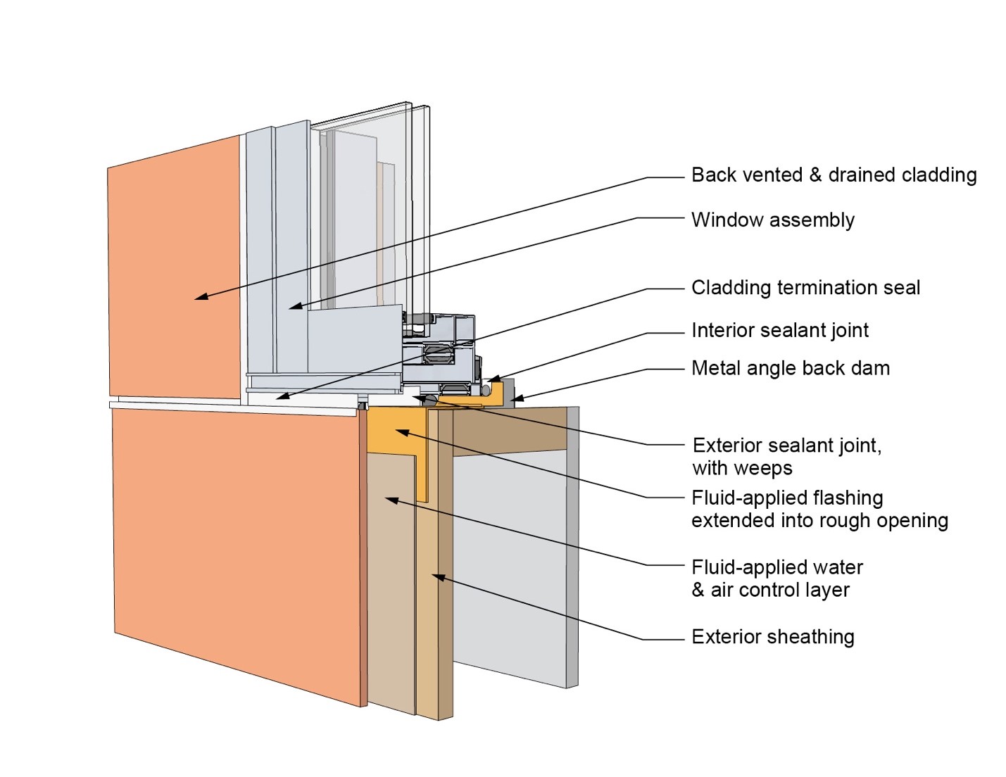
This drawing shows key sill details for a window installation using a fluid-applied flashing on a wall with a mechanically attached water and air control layer
Image
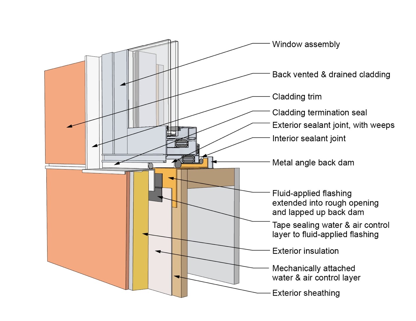
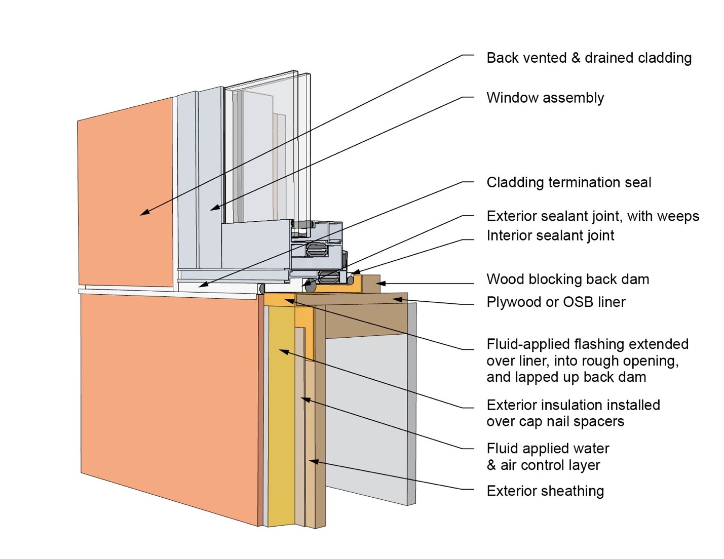
This drawing shows key sill details for a window installation using a fluid-applied flashing on a wall with a mechanically attached water and air control layer and continuous insulation
Image
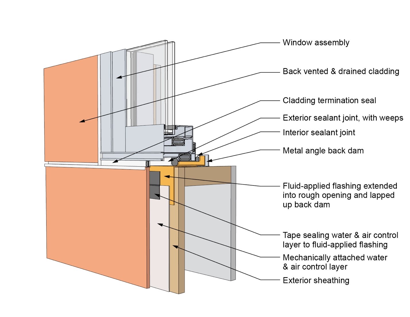
This drawing shows key sill details for a window installation using a self-adhered membrane tape flashing on a wall with a mechanically attached water and air control layer
Image
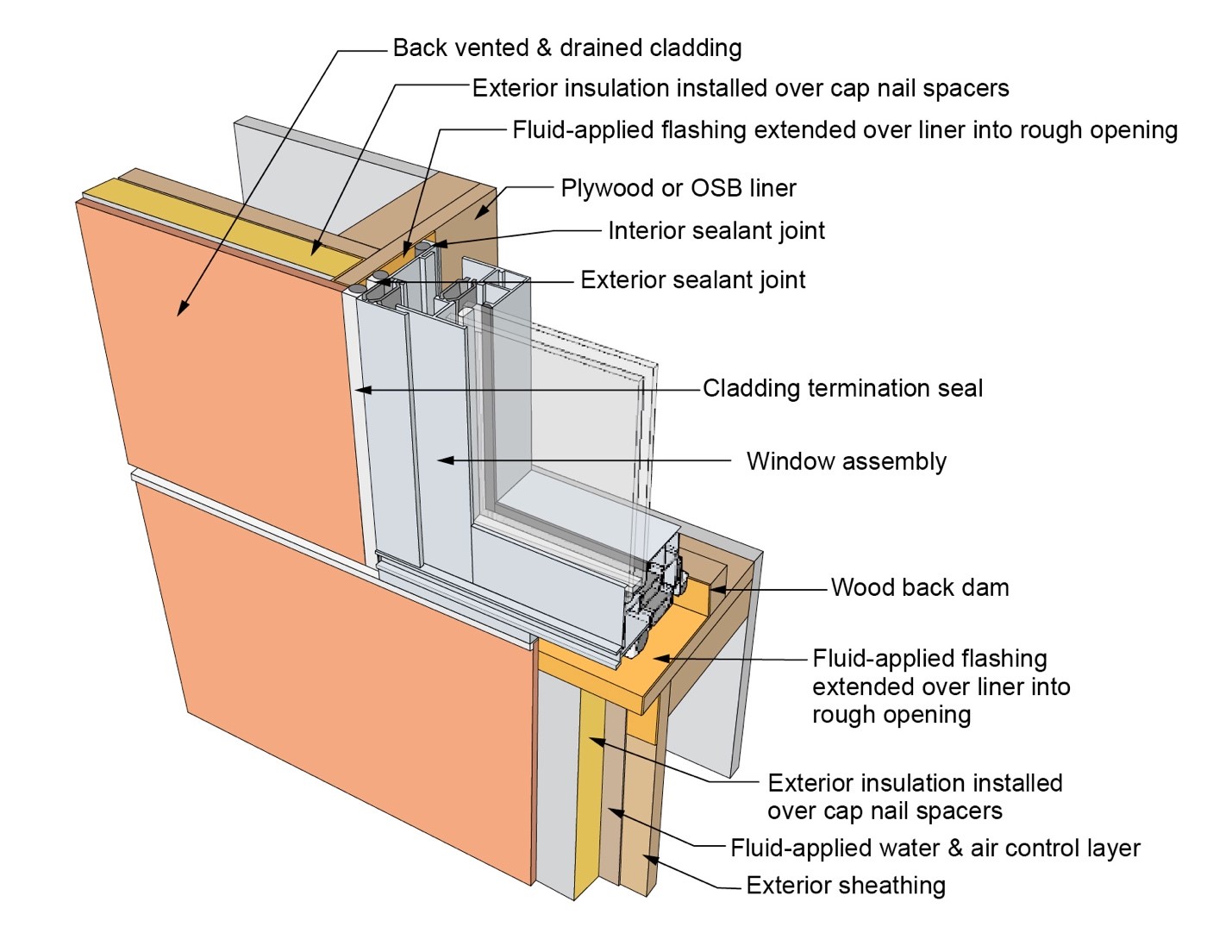
This drawing shows key sill details for an “outie” window installation using a fluid-applied flashing on a wall with a fluid-applied water and air control layer and continuous insulation
Image
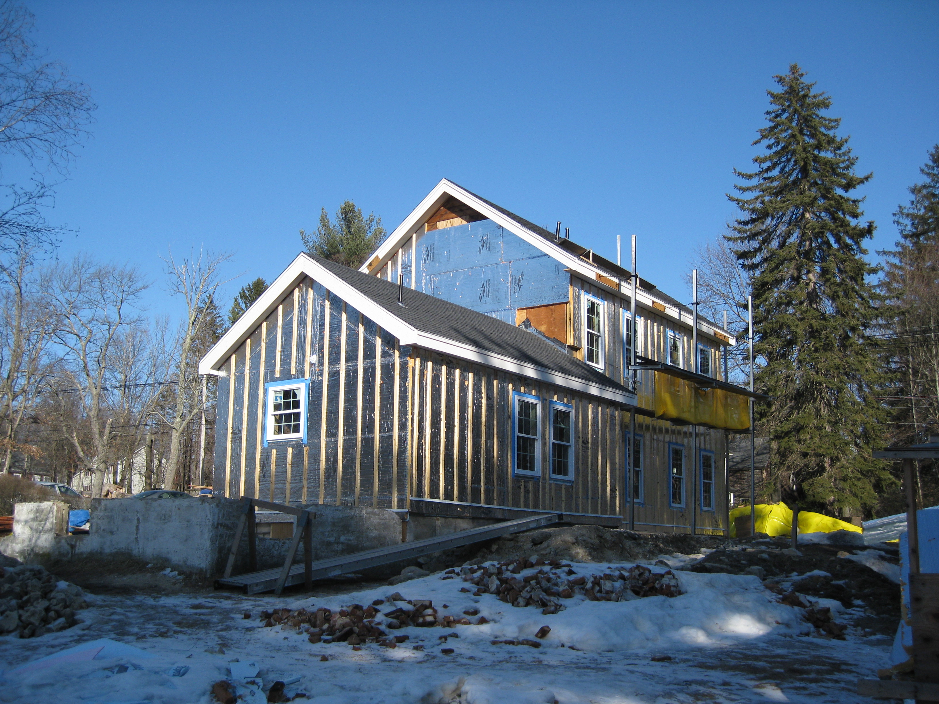
This farmhouse was retrofit by removing the existing siding and adding taped insulated sheathing and battens before installing new siding
Image
This finished retrofit installation of radiant barrier in attic shows the air spaces at the soffit and ridge to promote attic ventilation
Image
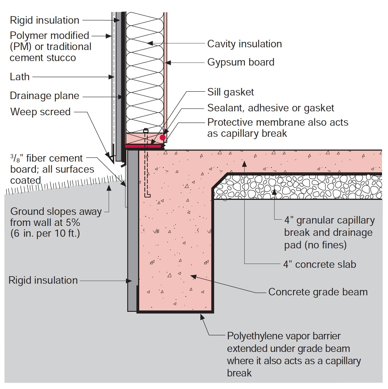
This house design in the Hot-Humid climate uses a slab foundation, masonry walls, and an Exterior Insulation Finish System (EIFS) cladding.
Image
Image
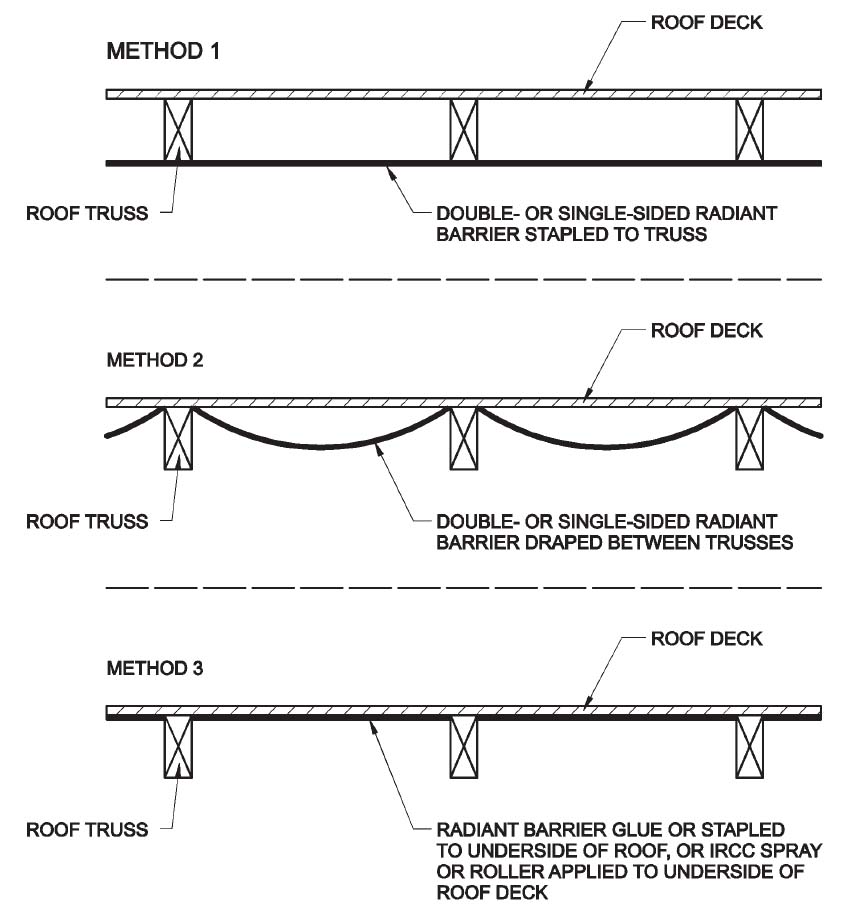
Three locations and methods for installing a roof deck radiant barrier in new construction
Image
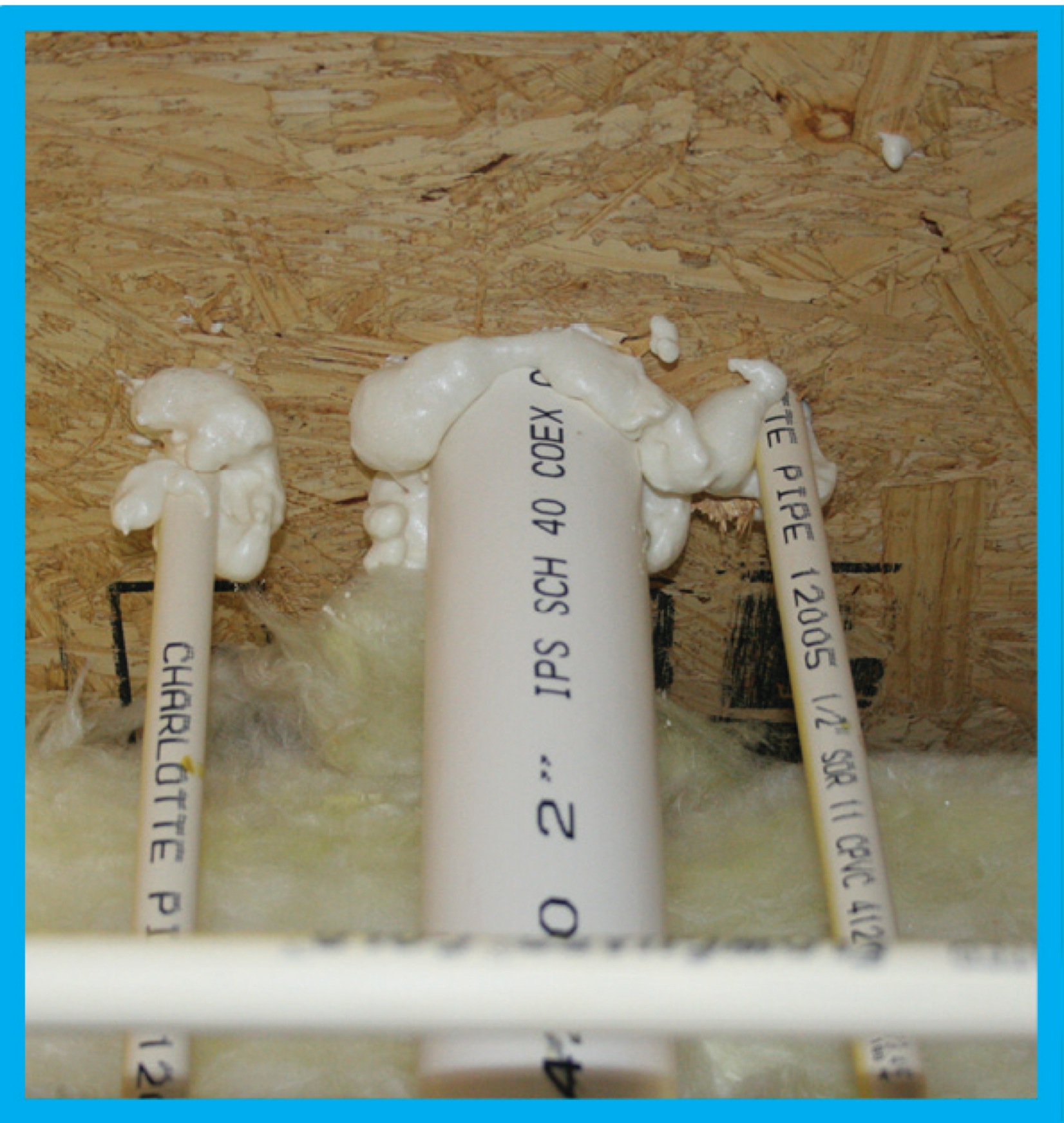
To ensure a complete air barrier between the garage and the house, the wall between the garage and the house was insulated and air-sealed with four inches of high-density spray foam.
Image
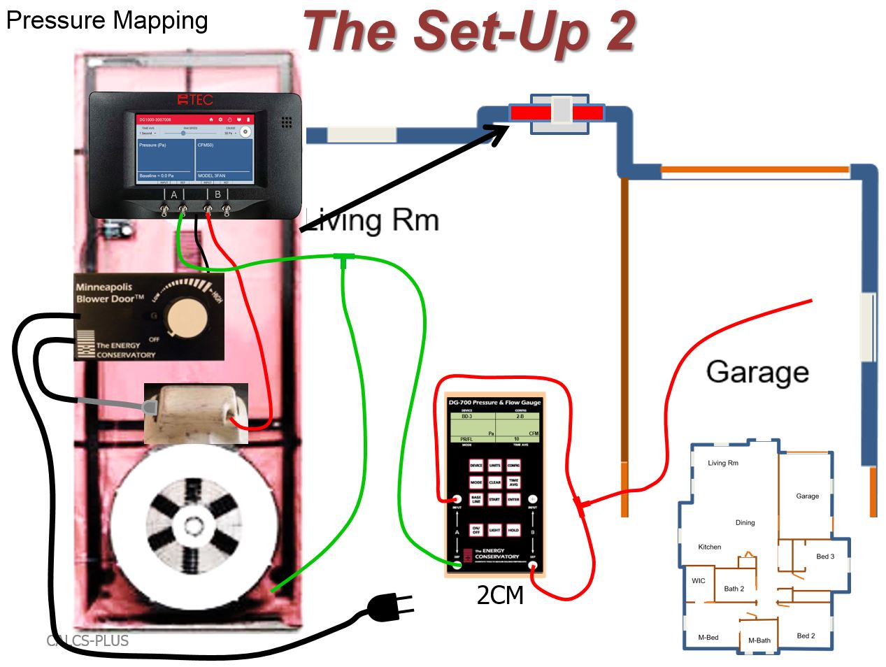
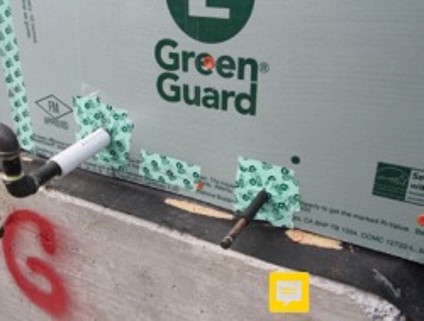
To test house-to-garage airtightness, after connecting the green tubing as shown, connect the red tubing as follows: connect the input tap on channel “A” of the two-channel manometer (2CM) to the reference tap on channel “B” of the 2CM
Image
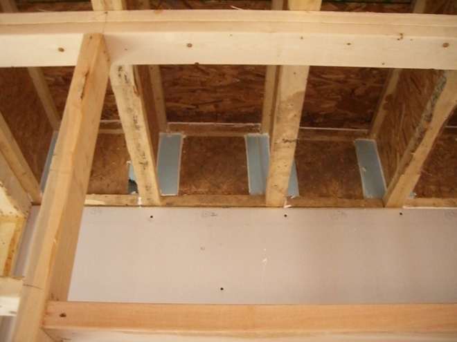
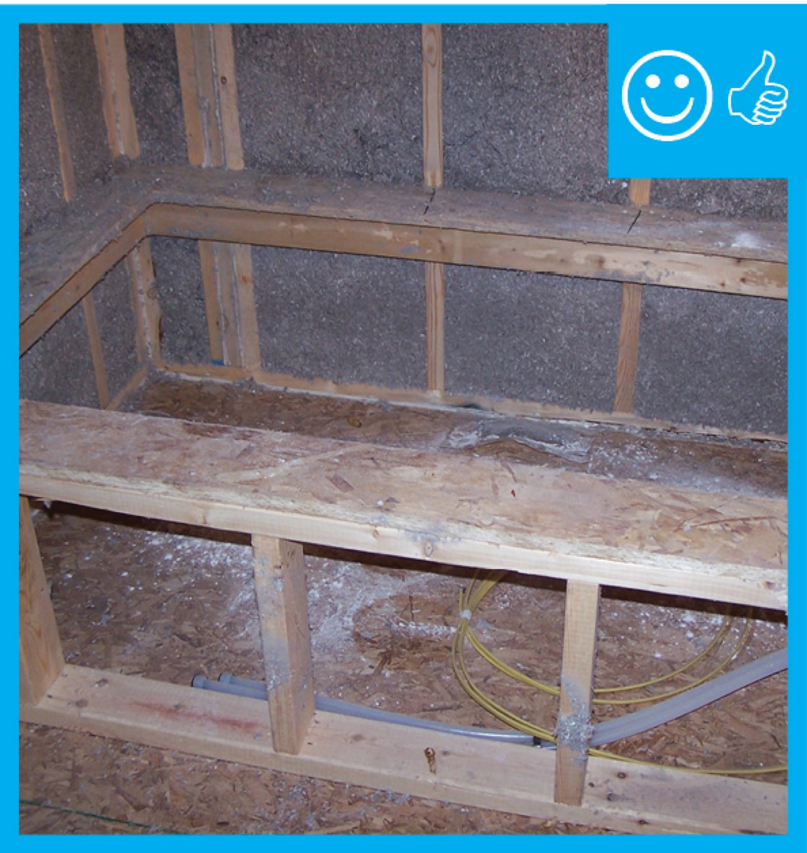
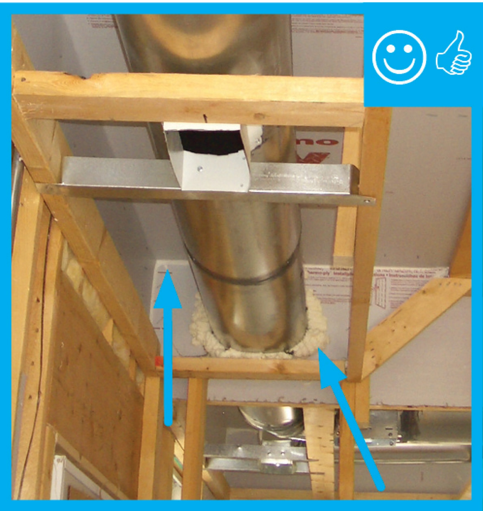
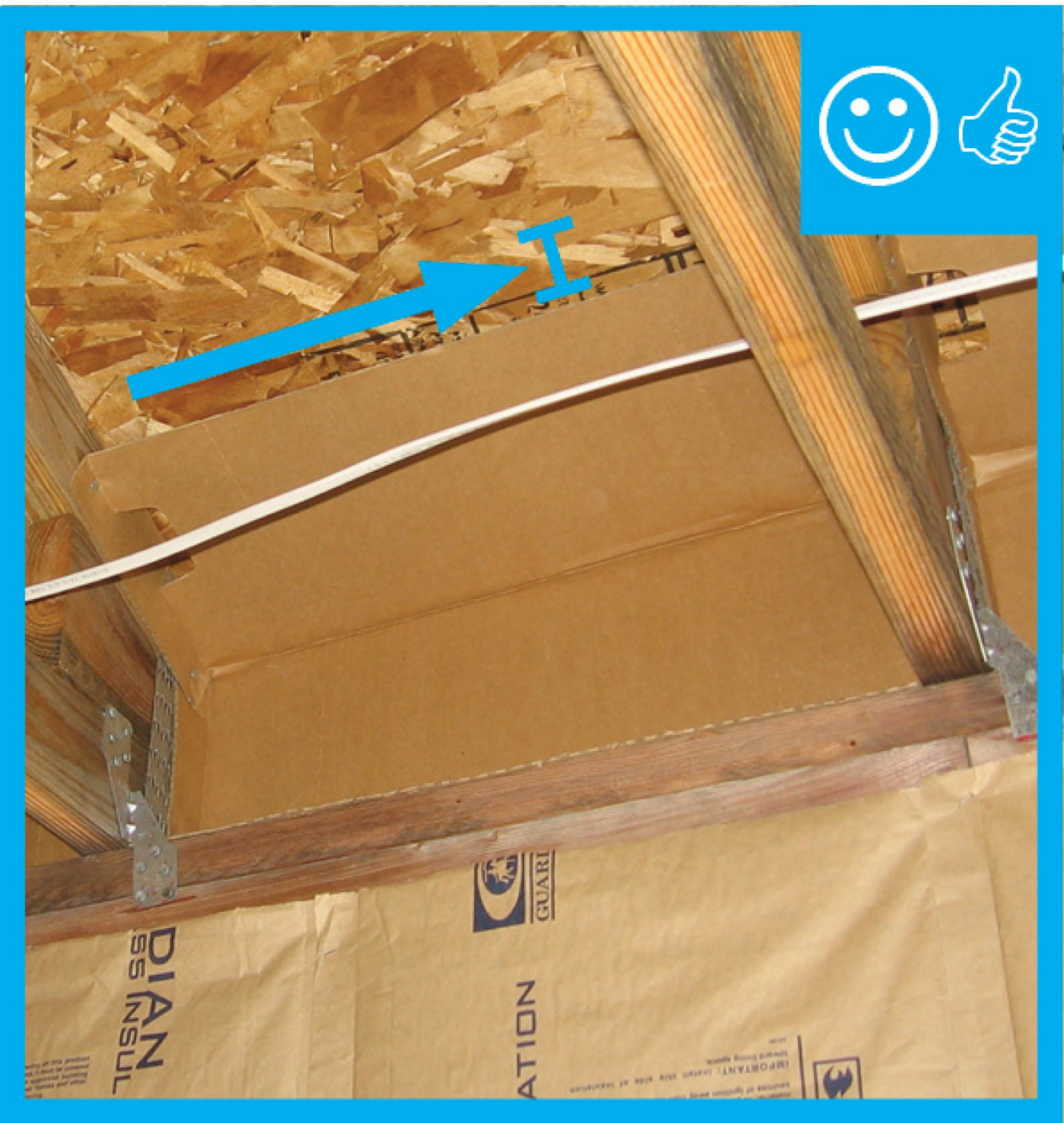
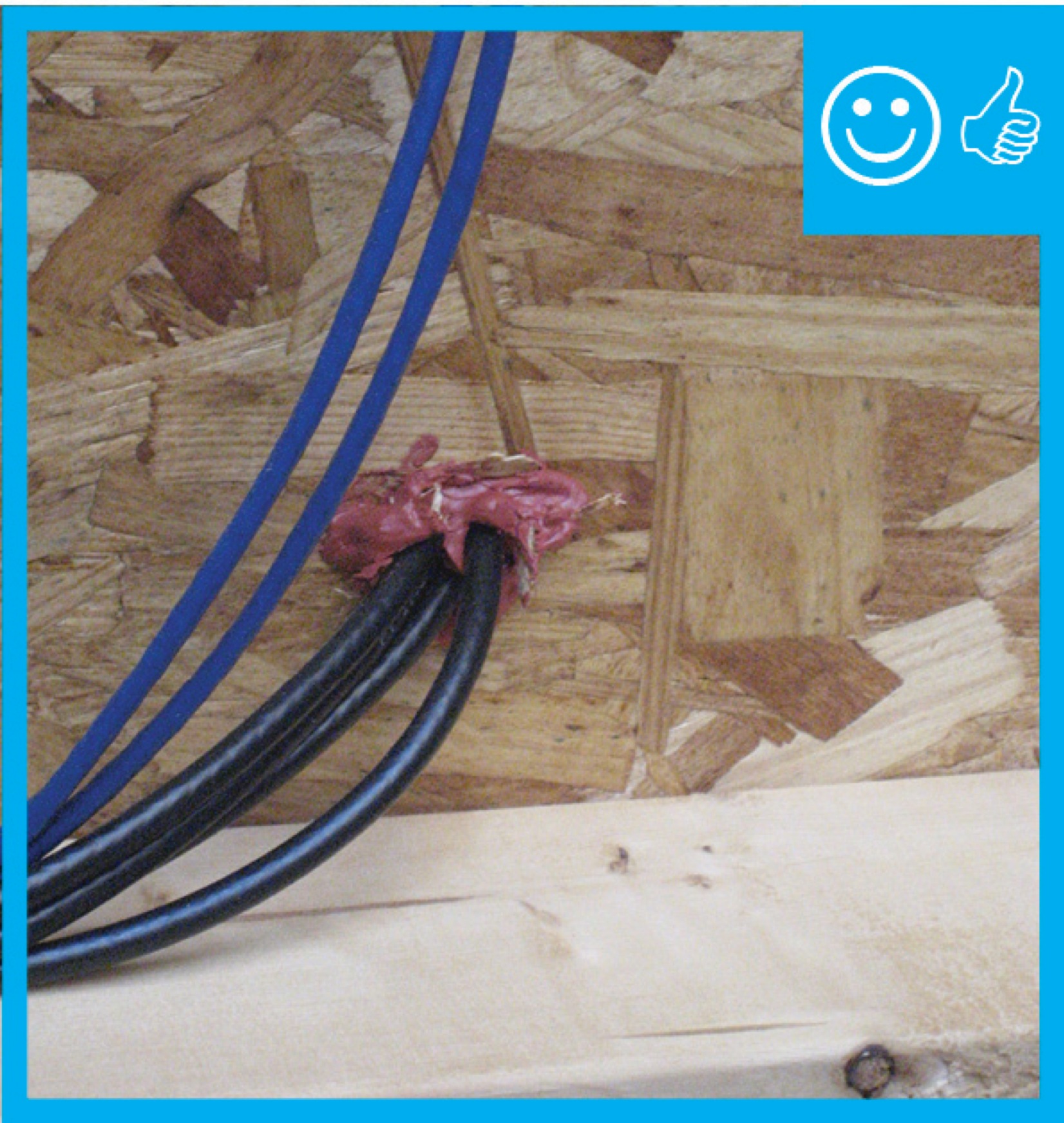
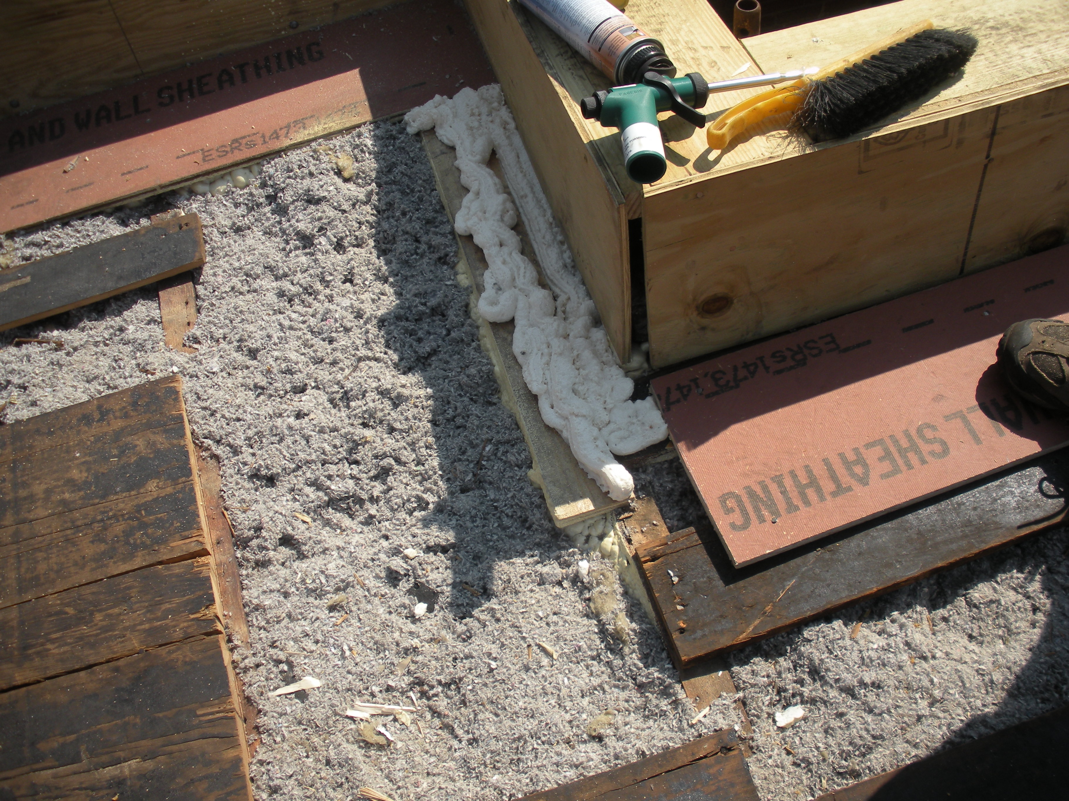
Use caulk or spray foam to air-seal all four edges of the blocking material in each joist bay.
Image
Image
Image
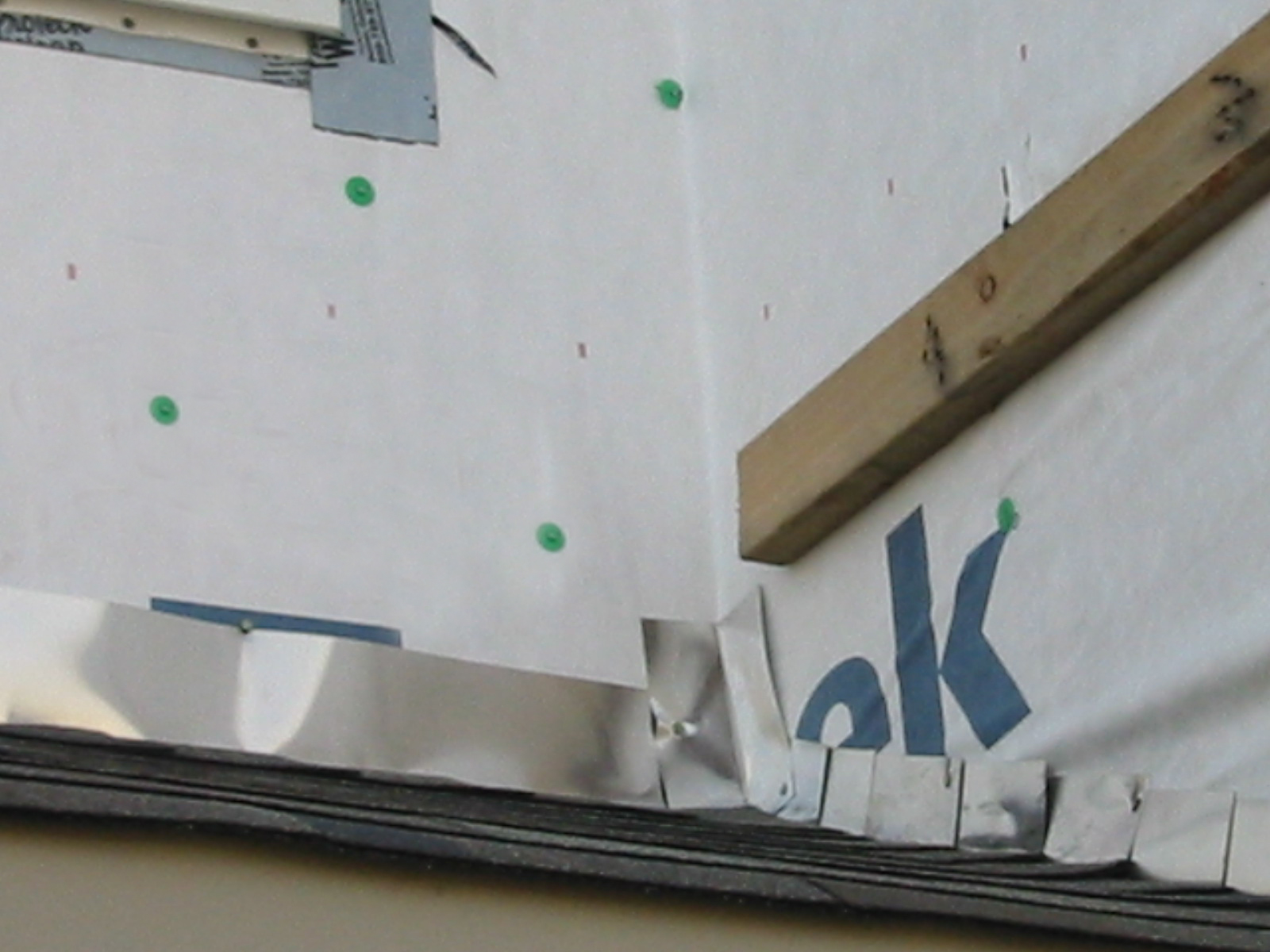
Weather resistant barrier is wrapped over the edge from roof to wall sheathing to provide a continuous air barrier at this transition.
Image
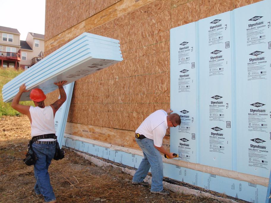
When rigid foam insulation is applied to the exterior side of the wall cavity under the cladding, with seams taped and an air gap provided, it acts as a vapor barrier, air barrier, and rain screen.
Image
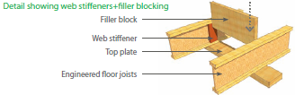
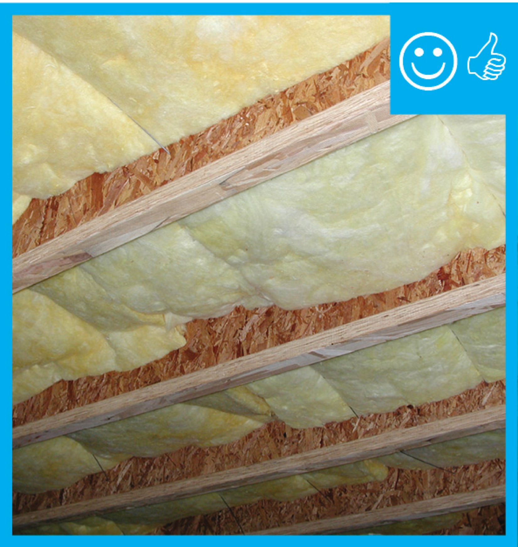
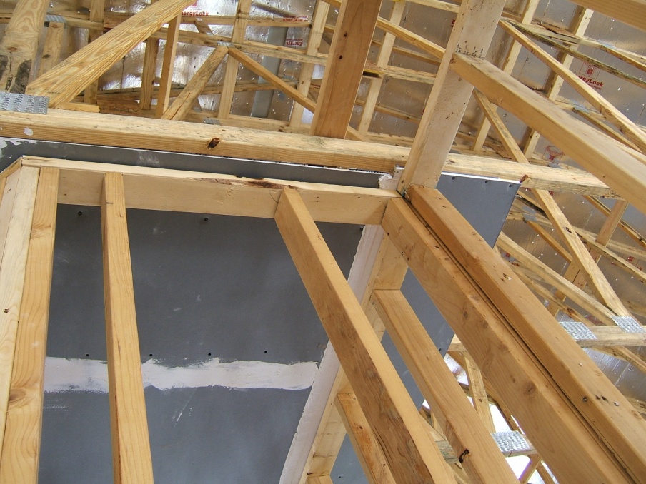
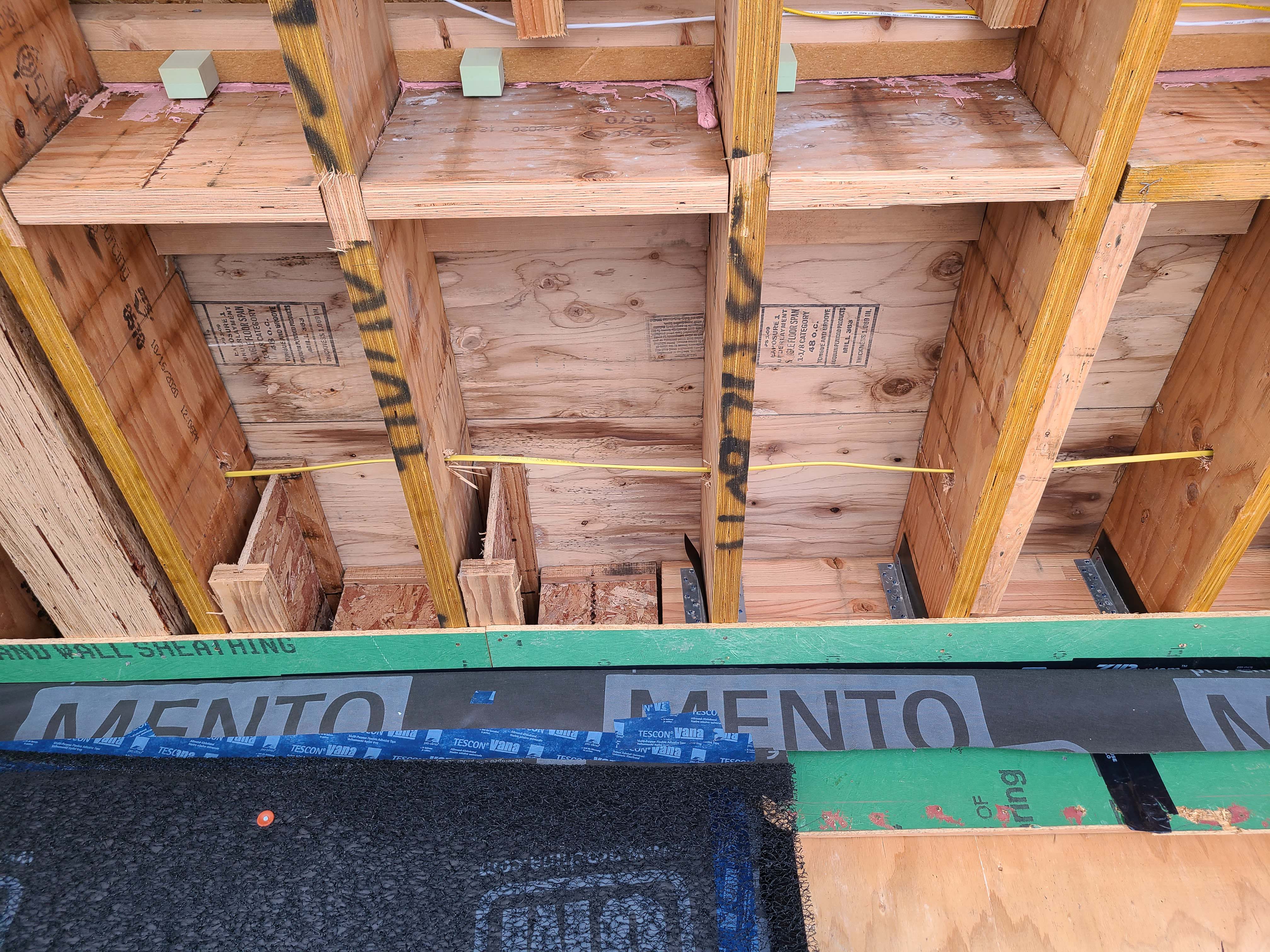
When using I-joists, make sure to fill in the gaps on each side of the blocking material to air-seal the joist bay where a wall separates conditioned and unconditioned spaces.
Image
Windows are installed as “outies” in this wall assembly using a self-adhered membrane water and air control layer with continuous exterior insulation
Image
Image
Image
Image
Image
Image
Image
Image
Image
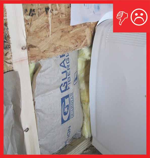
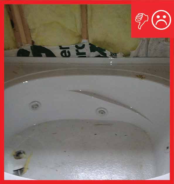
Wrong - Cantilevered floor joist bay cavities are not air sealed with a solid air barrier aligned with the exterior wall.
Image
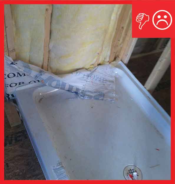
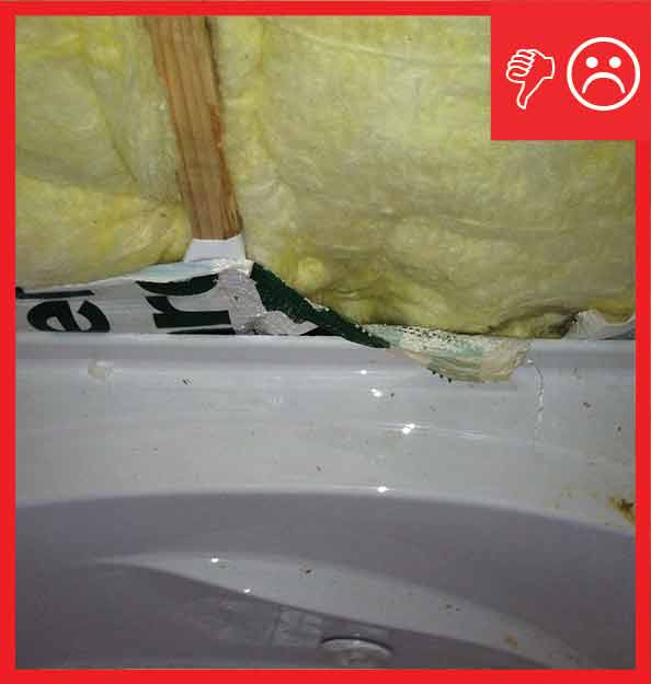
Wrong - Cantilevered joist bay cavities are not air sealed with a solid air barrier, allowing outside air to flow between floors.