Showing results 1 - 47 of 47
Image
Image
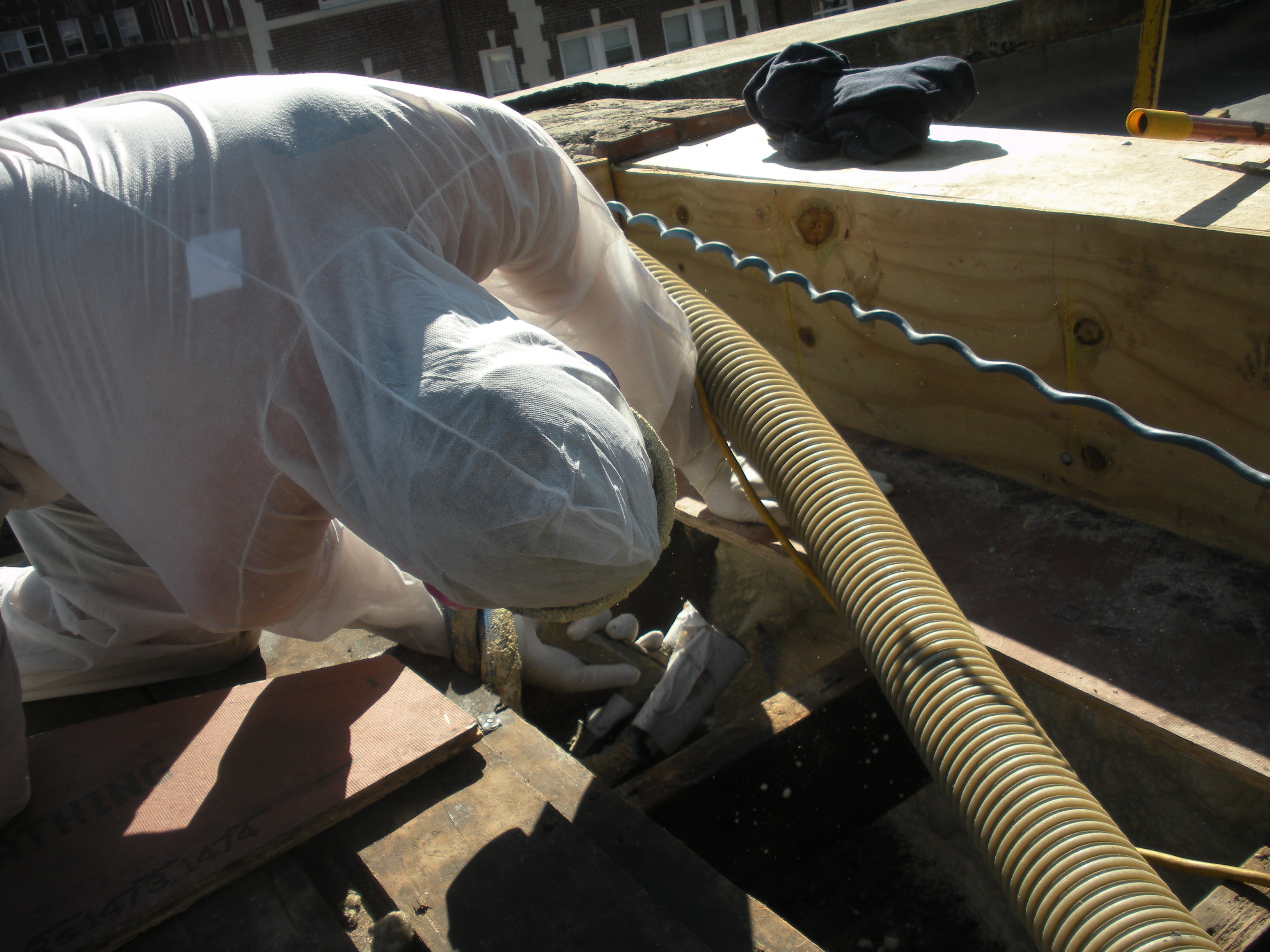
Closed-cell foam is sprayed into roof cavities along the masonry parapet wall to form a continuous air barrier between the wall and the sheathing of the flat roof
Image
Closed-cell spray foam fills the roof joist cavities forming an air barrier between the masonry parapet wall and the roof sheathing
Image
Image

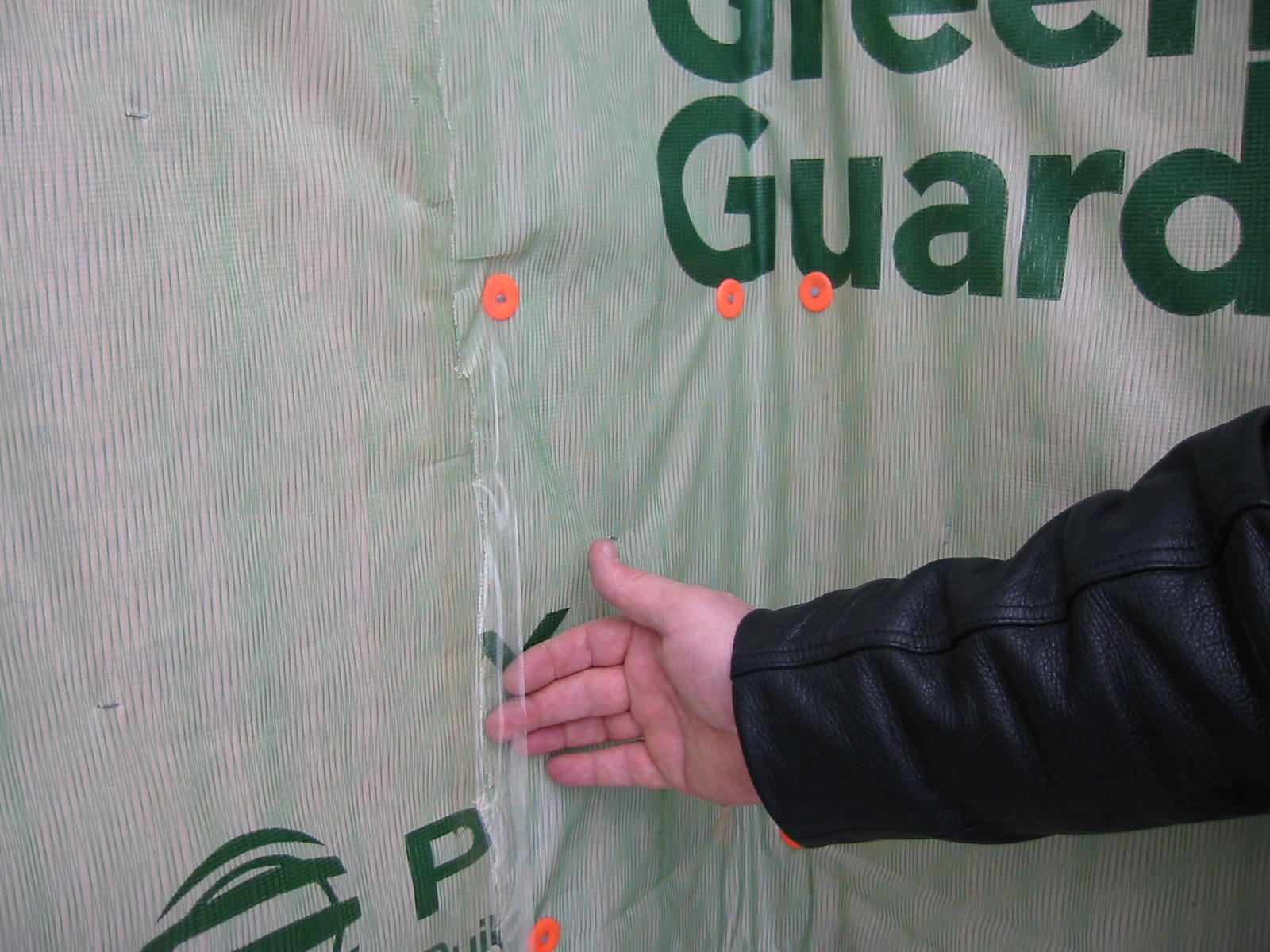
House wrap is sealed at all seams and overlaps flashing to serve as a continuous drainage plane over the exterior walls.
Image
Image
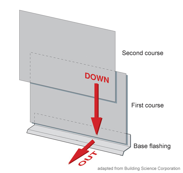
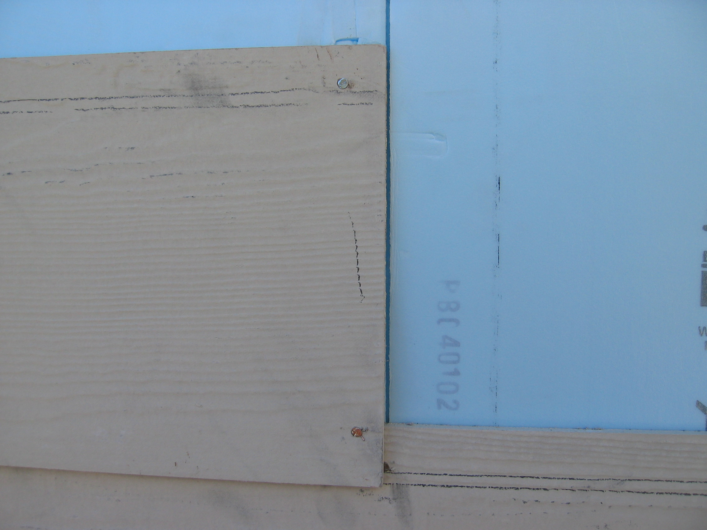
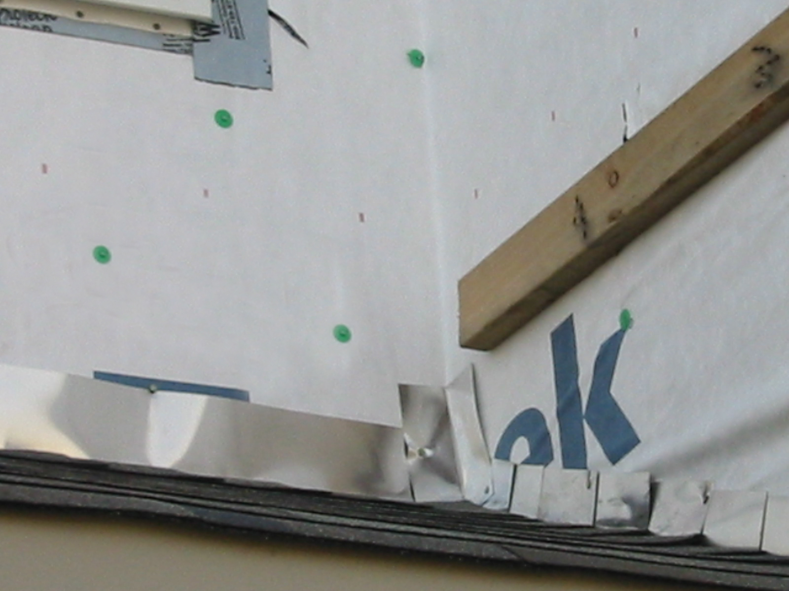
Install all layers of the drainage plane to overlap, not underlap, to direct bulk water down and out of the wall.
Image

Image
Image
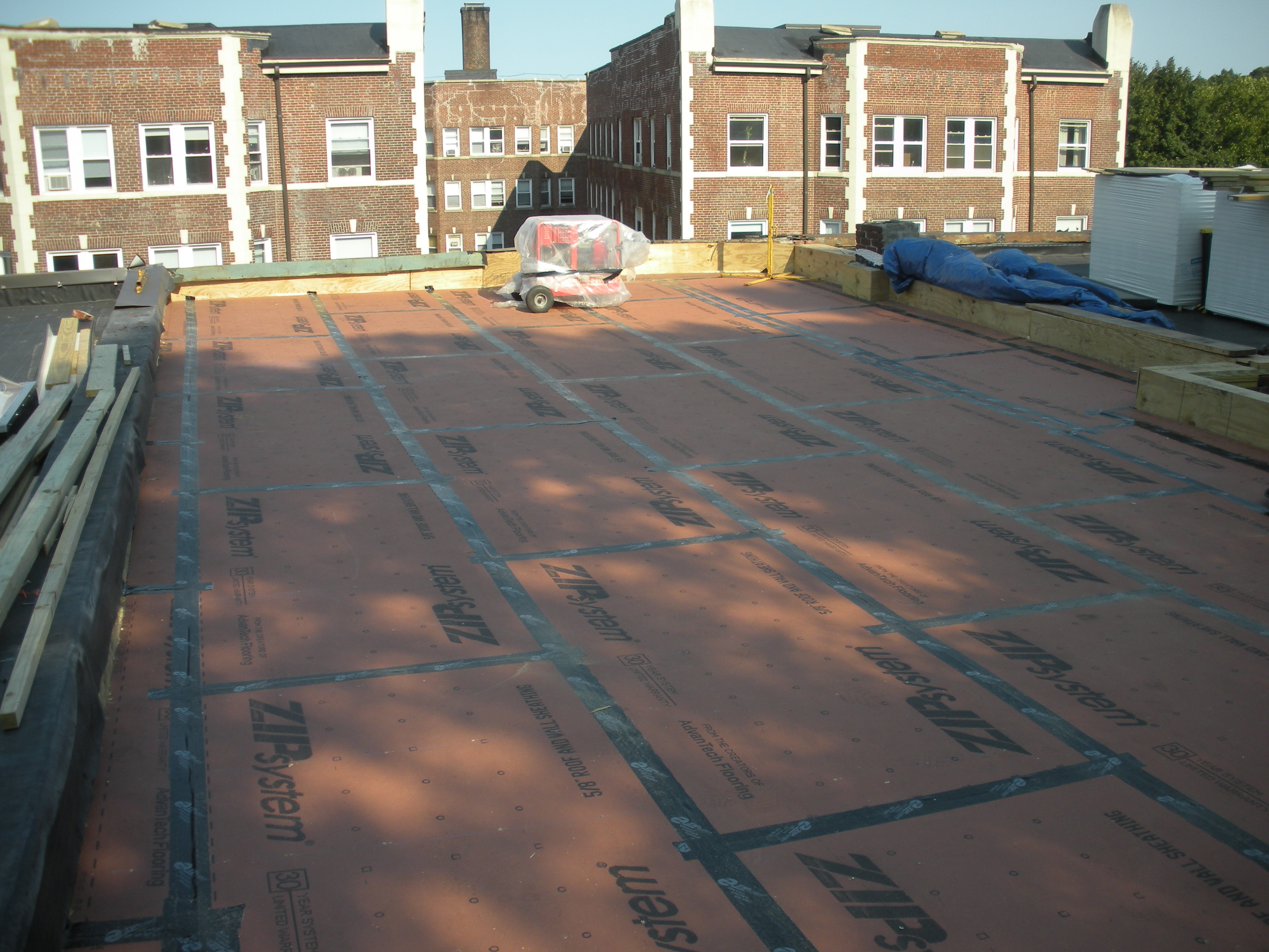
New coated OSB roof sheathing is installed over the existing sheathing of the flat roof and taped at the seams to provide a continuous air barrier
Image

Right - House wrap is overlapped “shingle” style to direct moisture down and away from the house; seams will be taped so house wrap serves as both an air and weather barrier.
Image
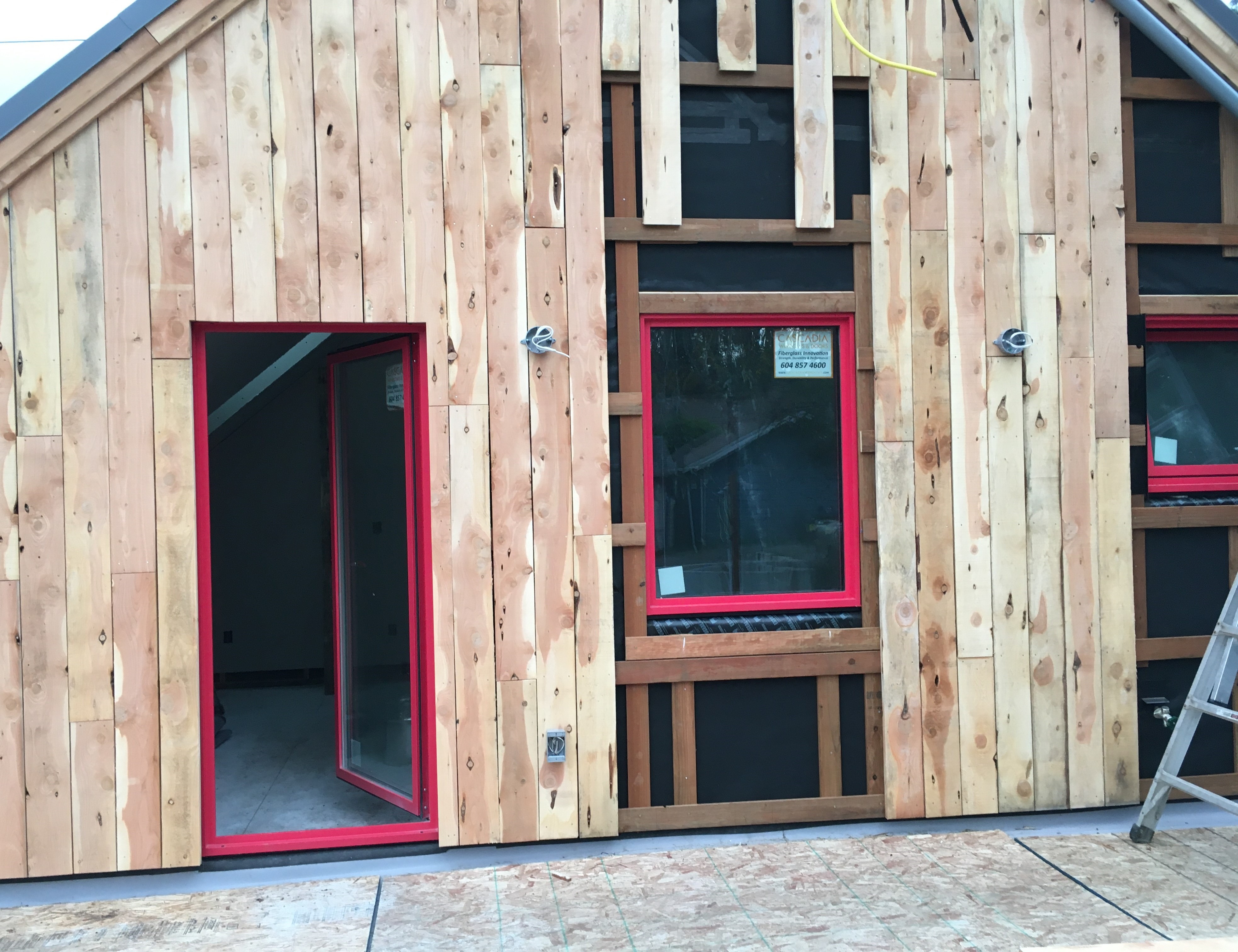
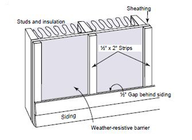
Right - This cedar siding is installed over furring strips which allow an air and drainage gap behind the siding.
Image
Right – The building felt is installed on all exterior walls and provides a complete drainage system
Image
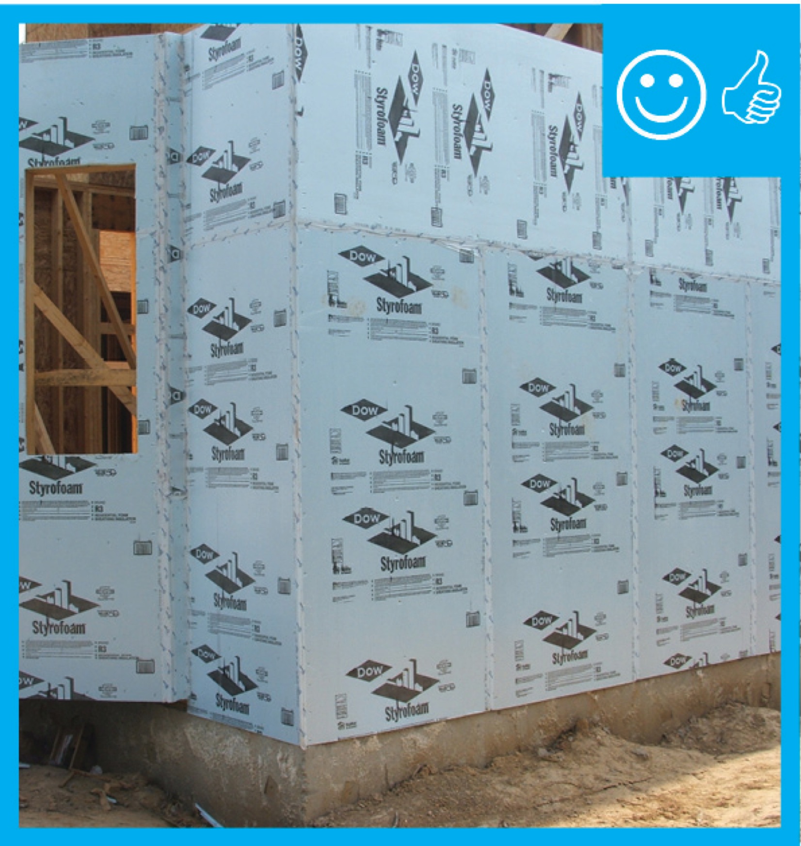
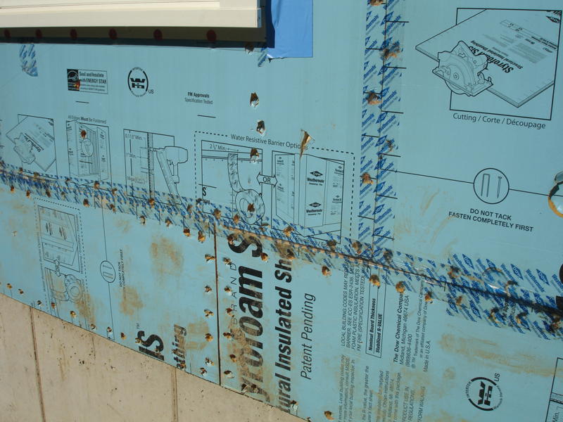
Right – The rigid insulation covers all exterior walls and all seams are taped to provide a complete drainage system
Image
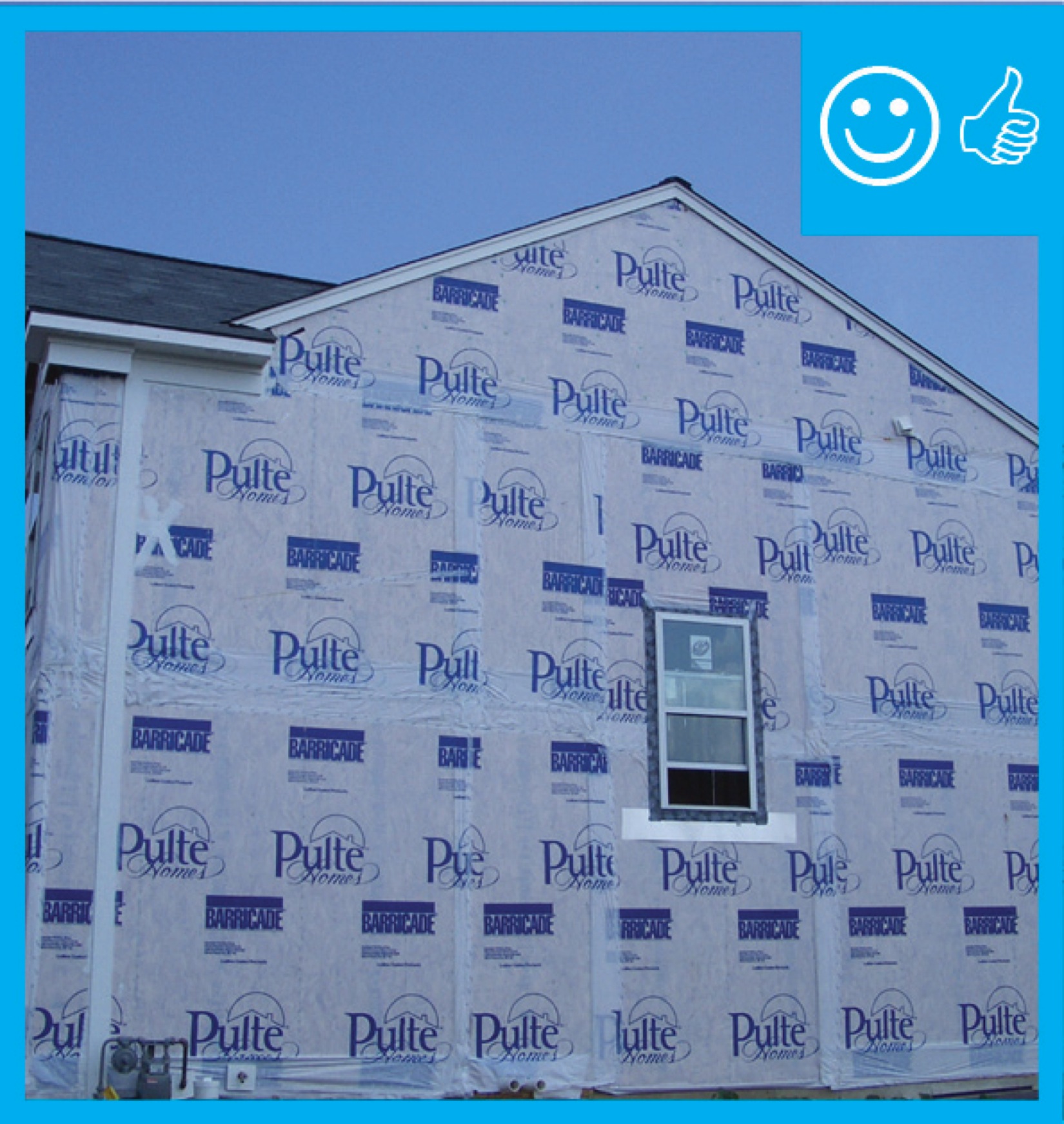
Right – The water-resistant barrier covers the entire house and the seams are taped to provide a complete drainage system
Image
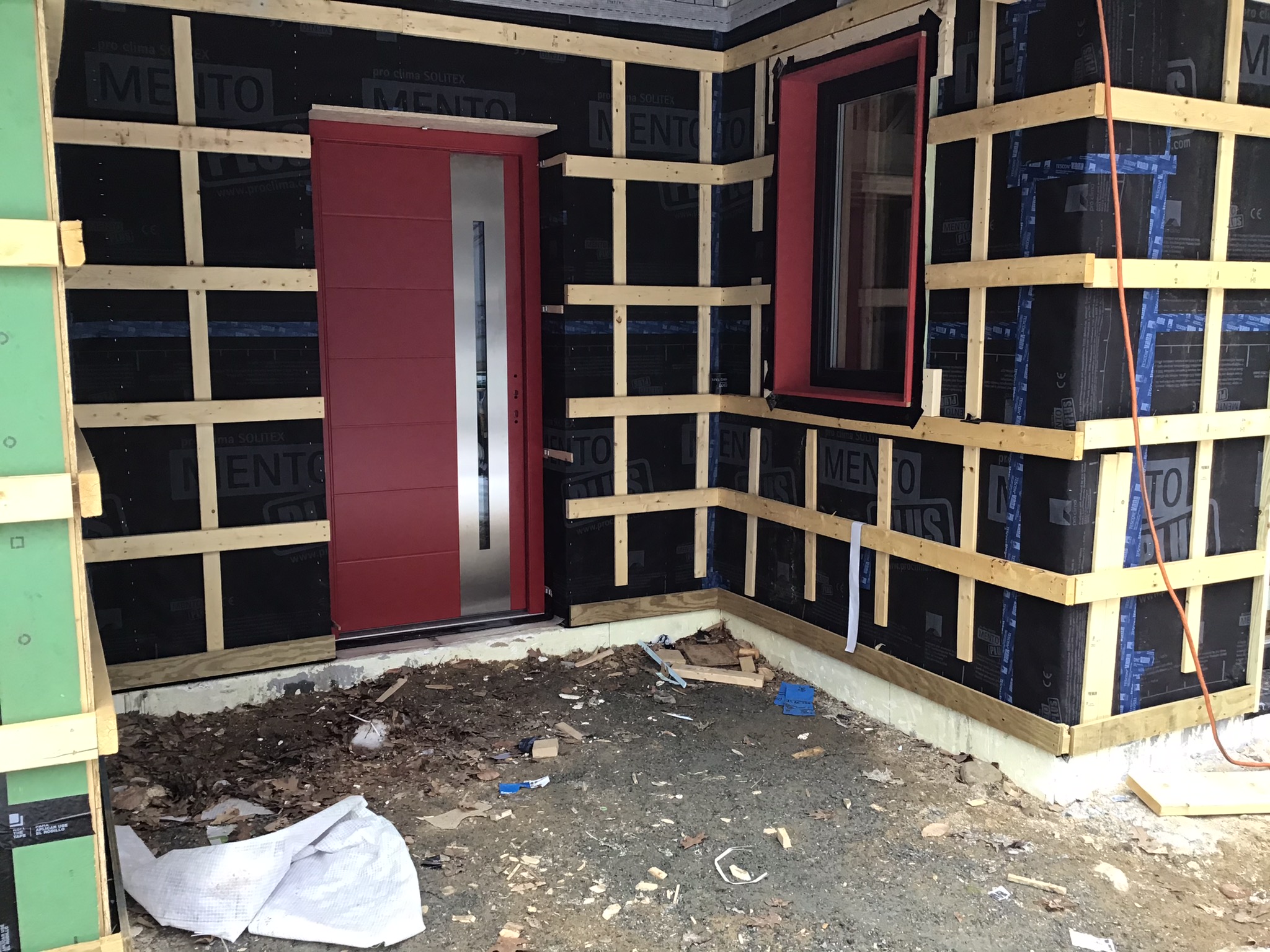
Right – Vertical and horizontal furring strips are installed over a breathable membrane weather resistant barrier to create an air gap and drainage plane behind the wood siding that will be installed next.
Image
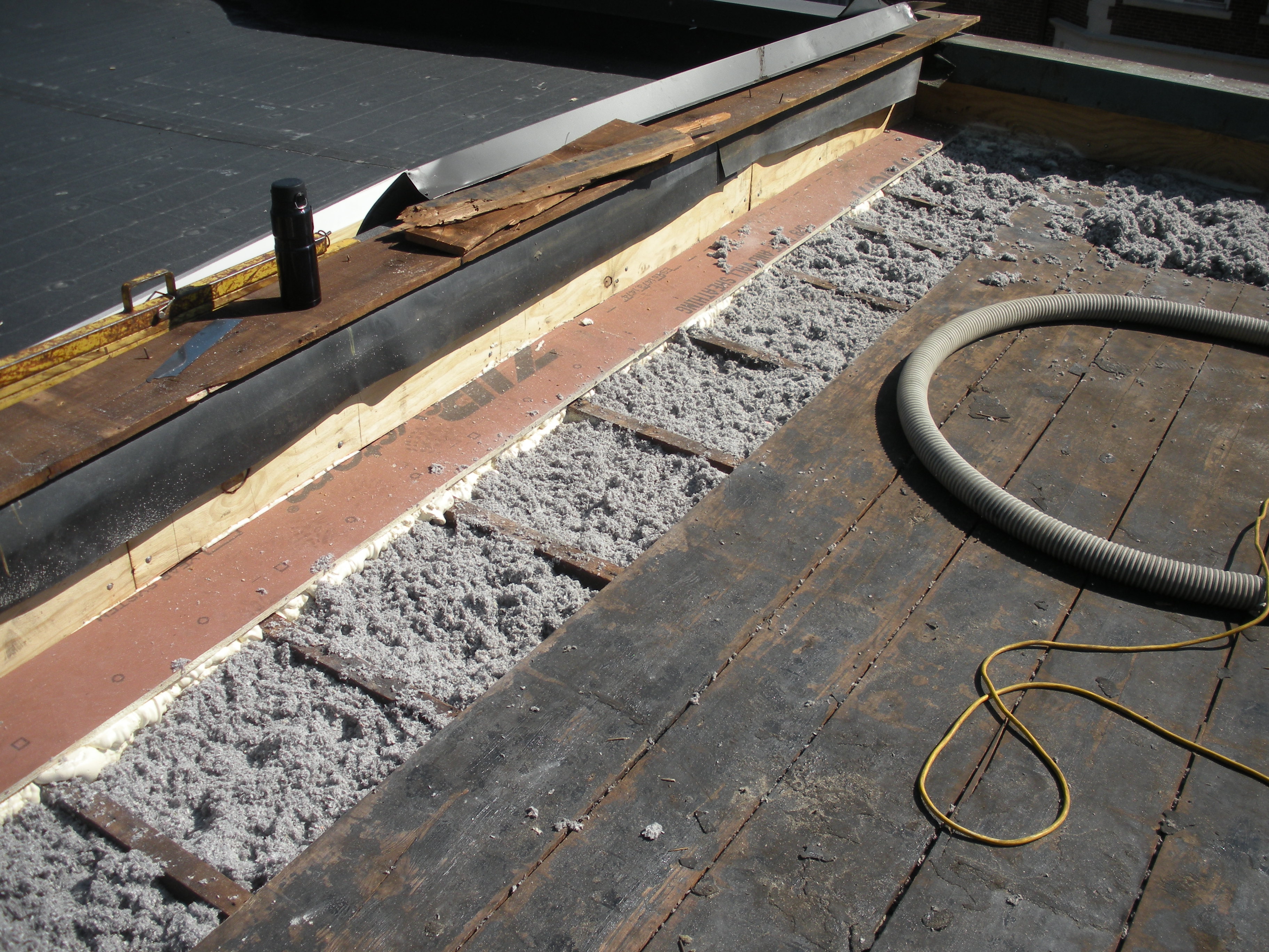
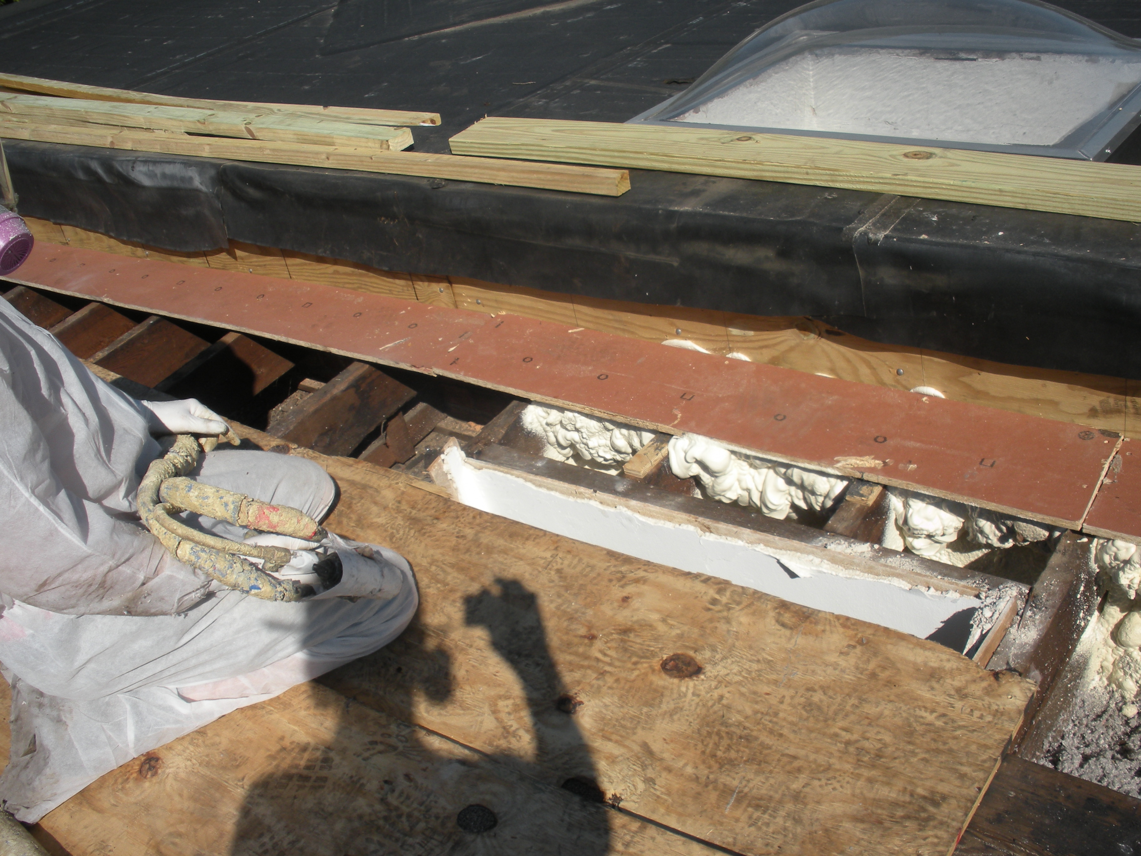
Roofing paper protects the top of the new plywood parapet while the base of the parapet is air sealed with spray foam and fibrous insulation is installed in the rafter cavities in this flat roof retrofit
Image
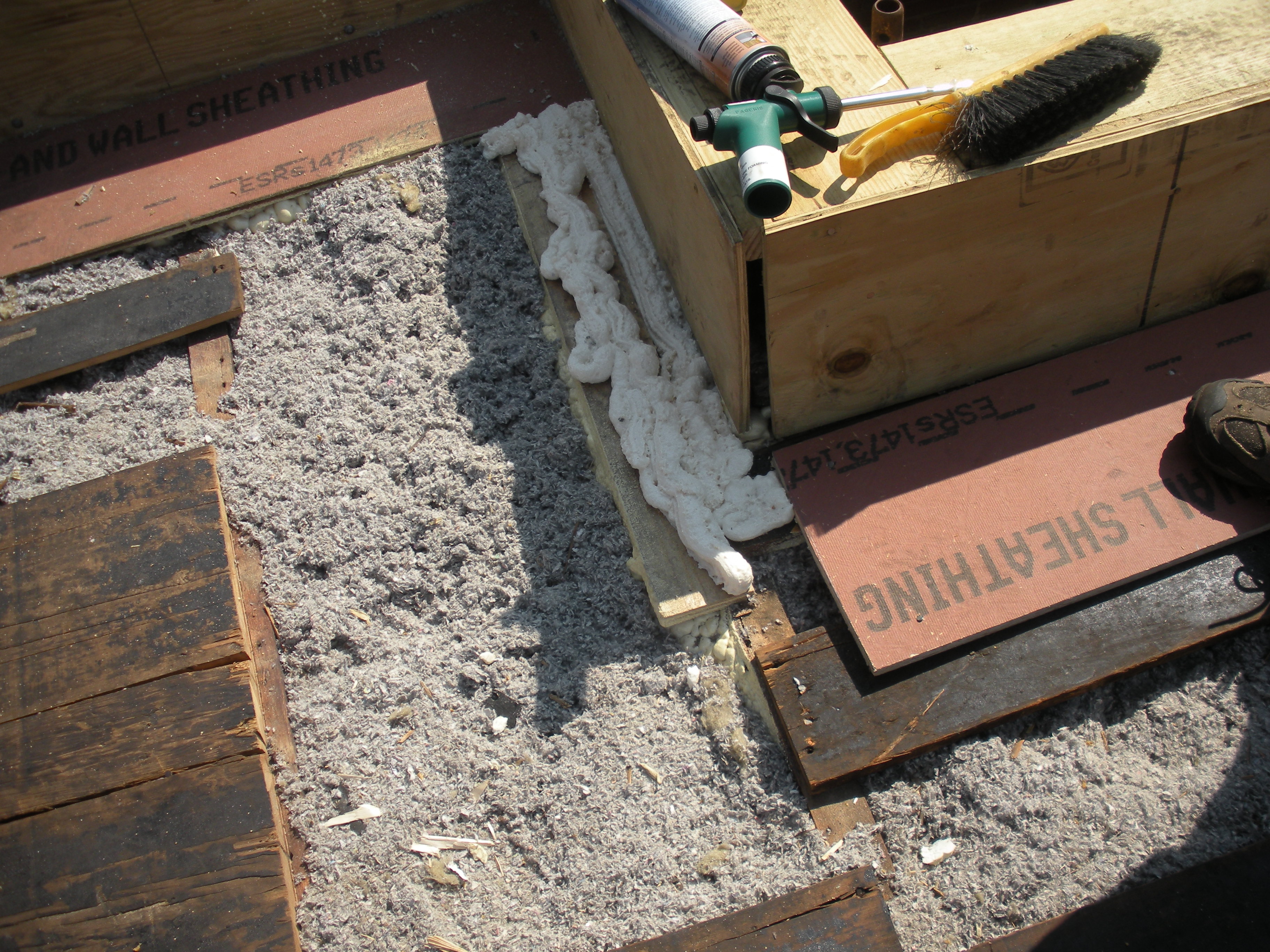
The base of the plywood parapet is air sealed with spray foam and fibrous insulation is installed in the rafter cavities in this flat roof retrofit
Image

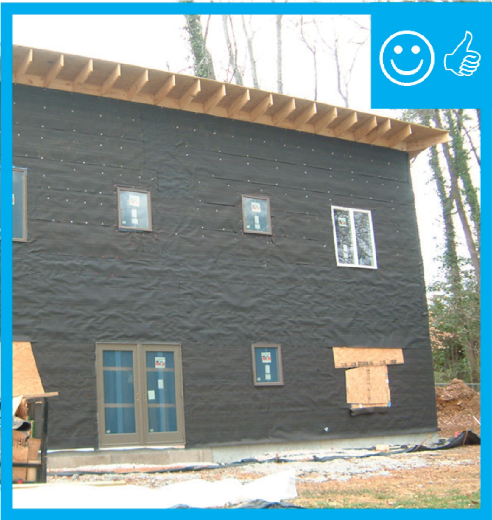
The black coating on these walls is a liquid-applied asphalt-based air and moisture barrier.
Image
Image
Image
Image

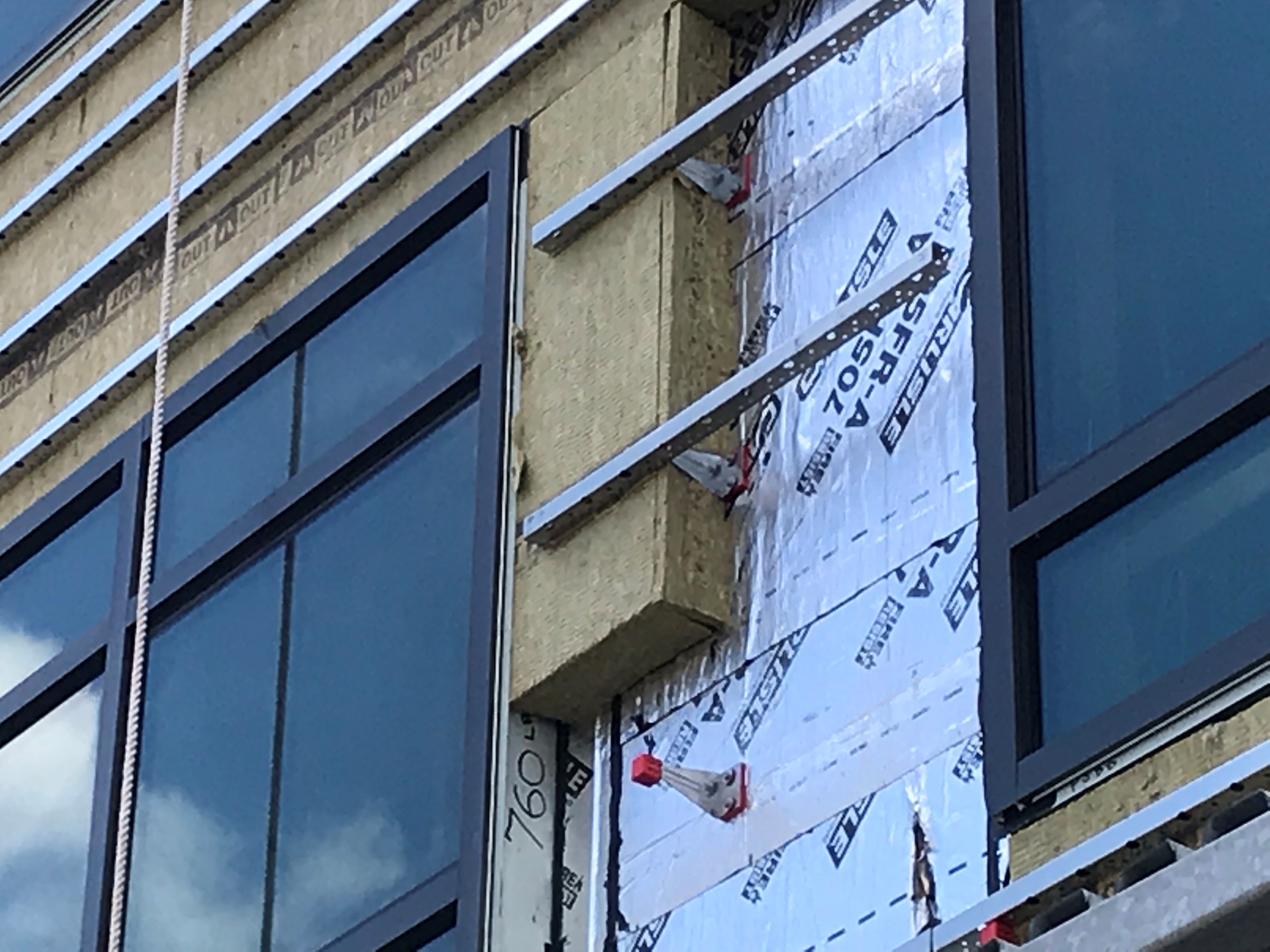
The windows in this building are connected to the fully adhered water and air control layer using fluid-applied flashing
Image
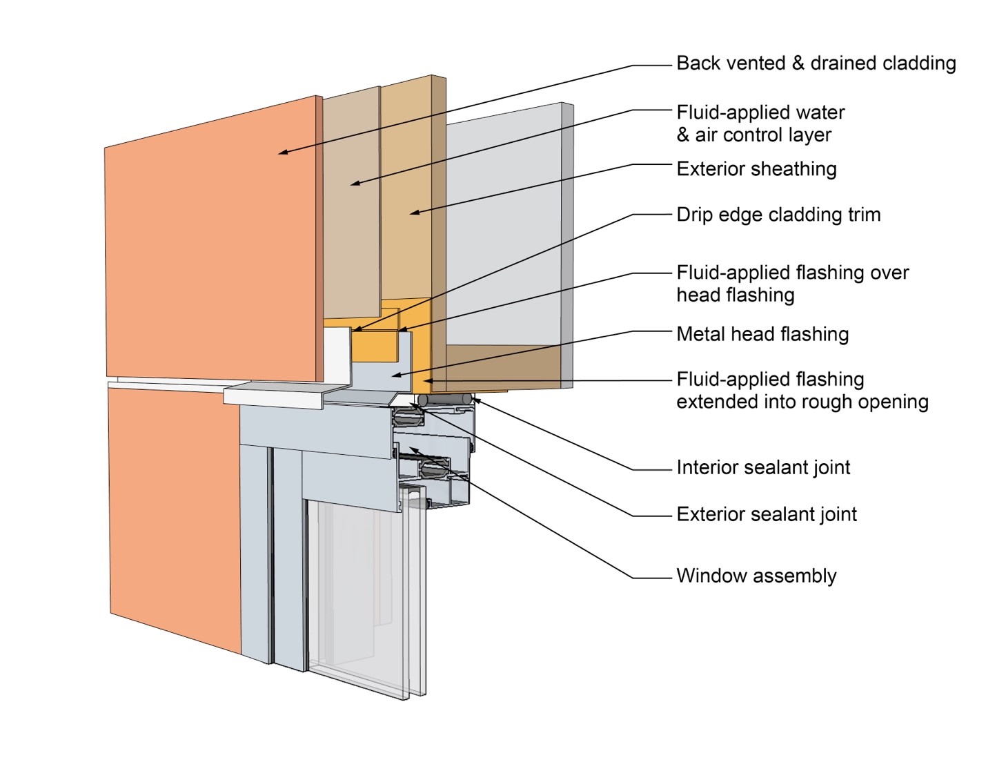
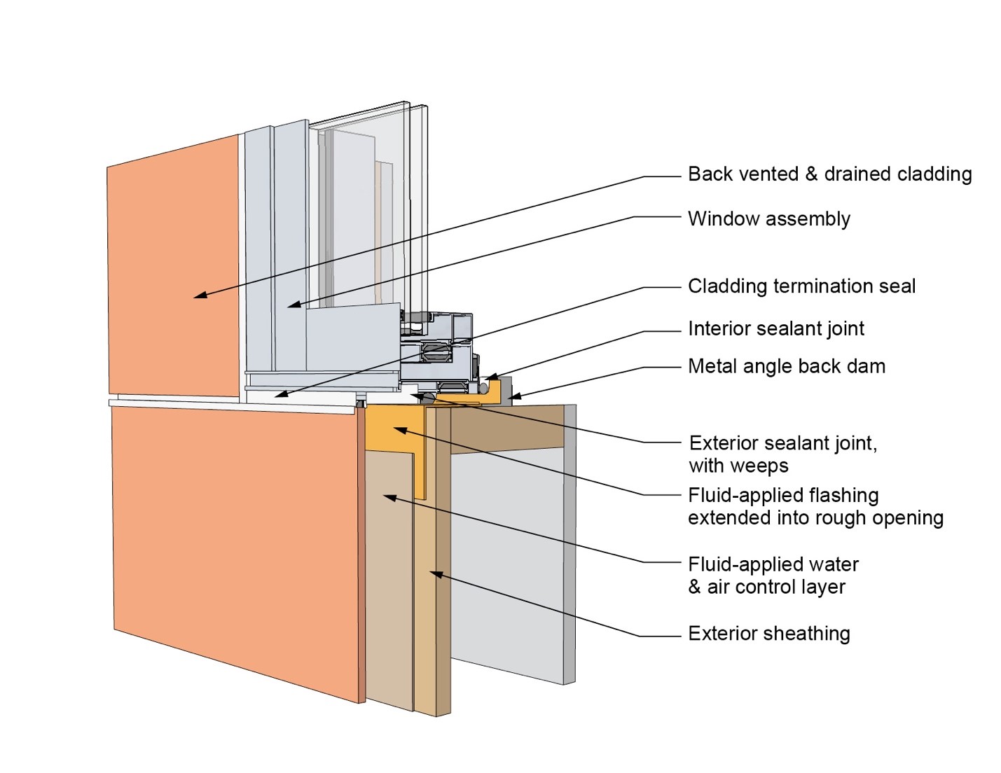
This drawing shows key head details for a window installation using a fluid-applied flashing on a wall with a fluid-applied water and air control layer
Image
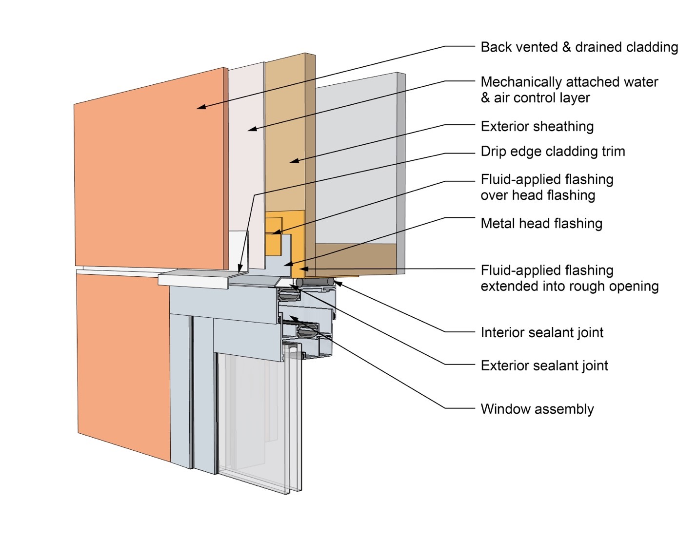
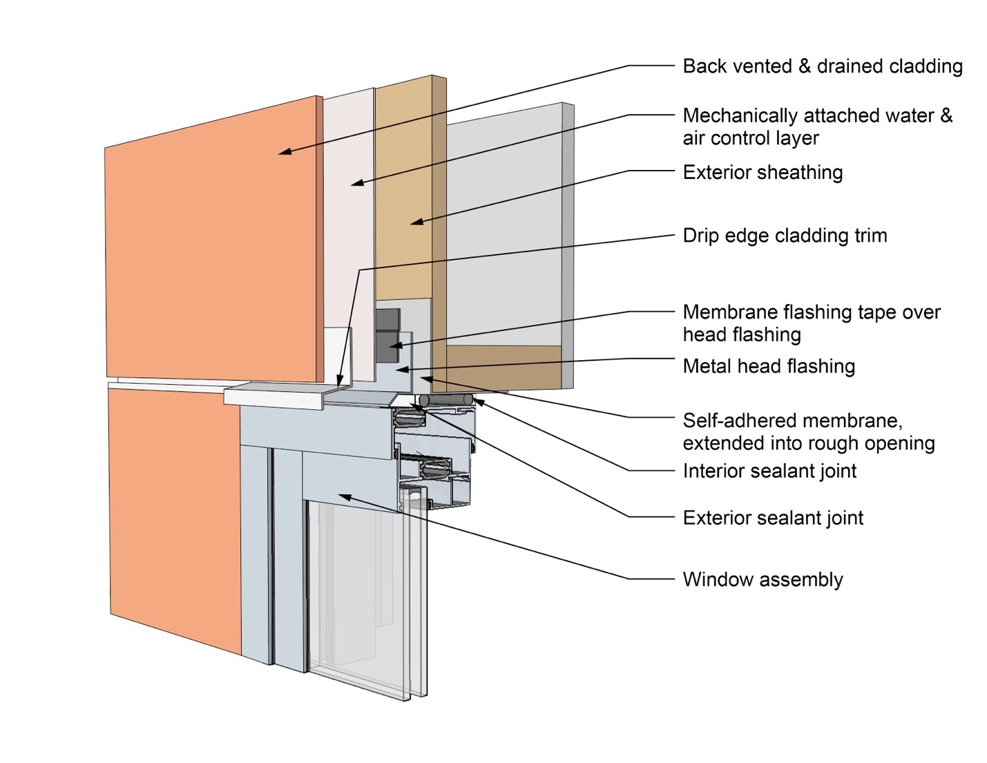
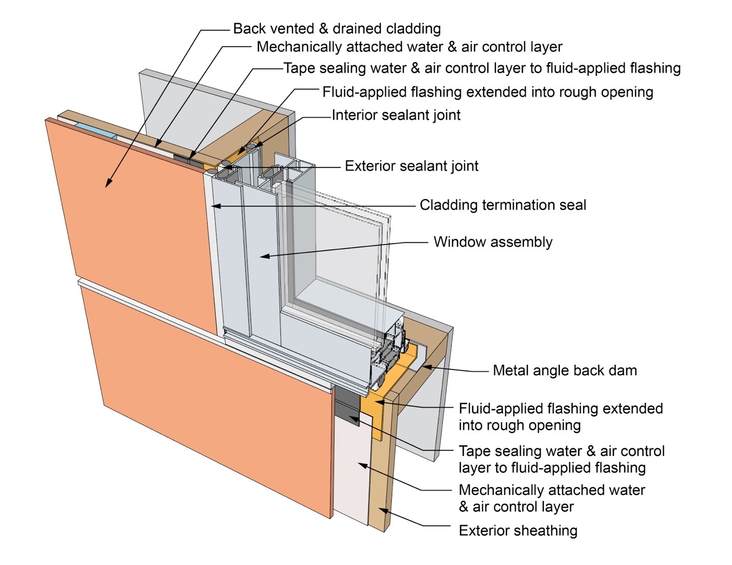
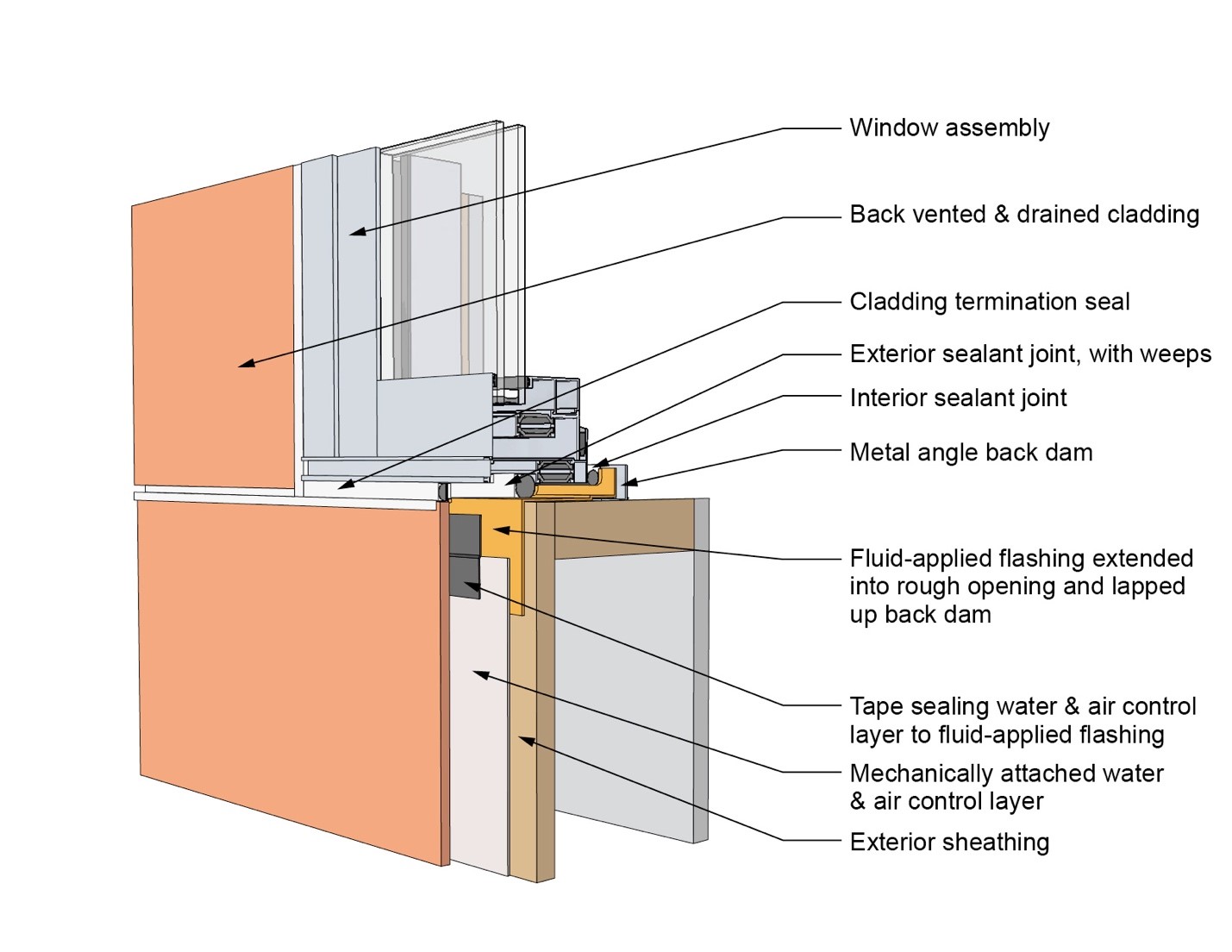
This drawing shows key head details for a window installation using a fluid-applied flashing on a wall with a mechanically attached water and air control layer
Image
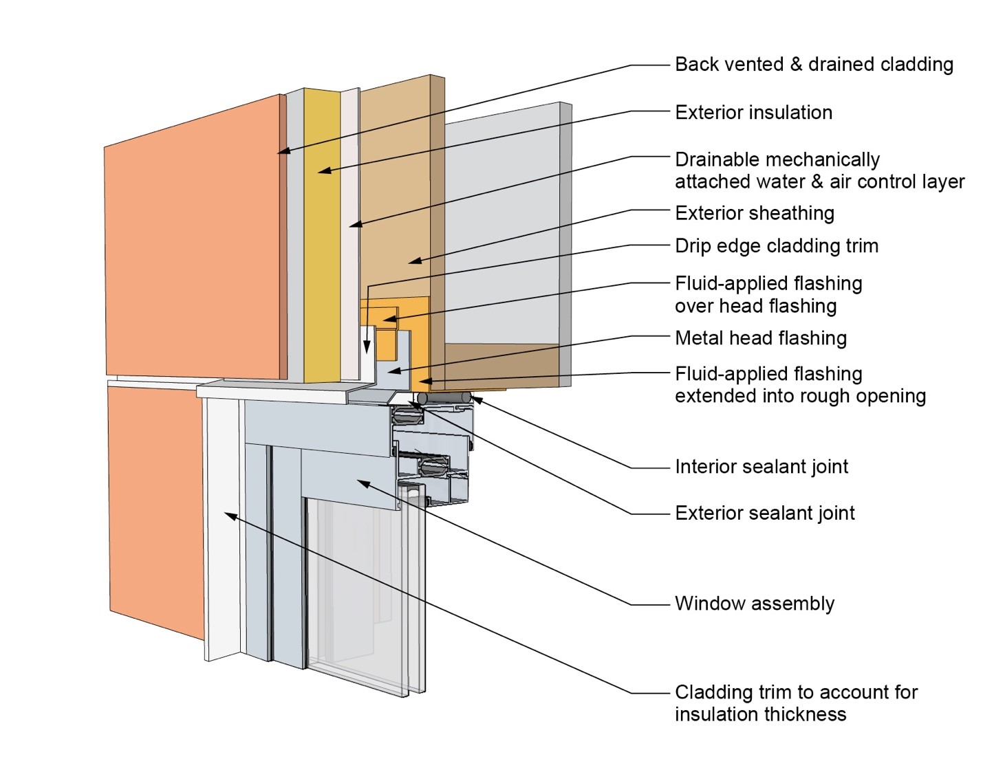
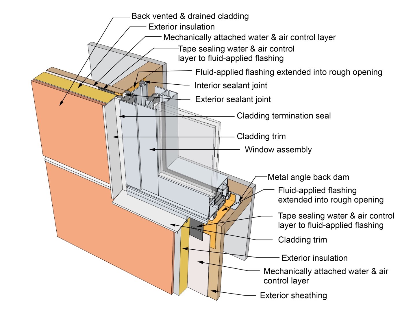
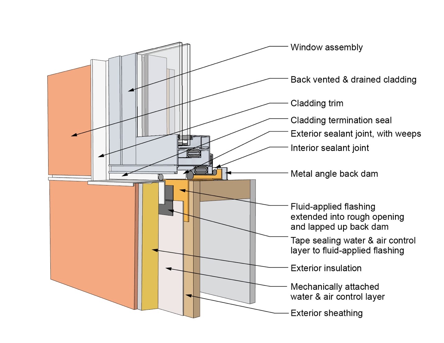
This drawing shows key head details for a window installation using a fluid-applied flashing on a wall with a mechanically attached water and air control layer and continuous insulation
Image
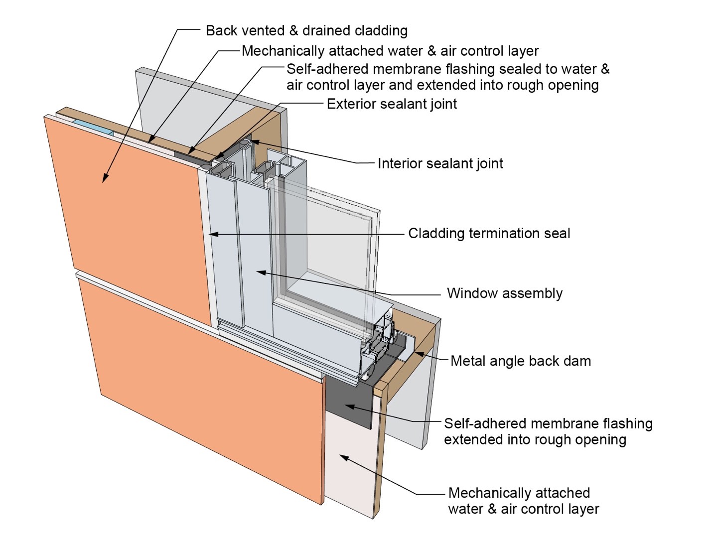
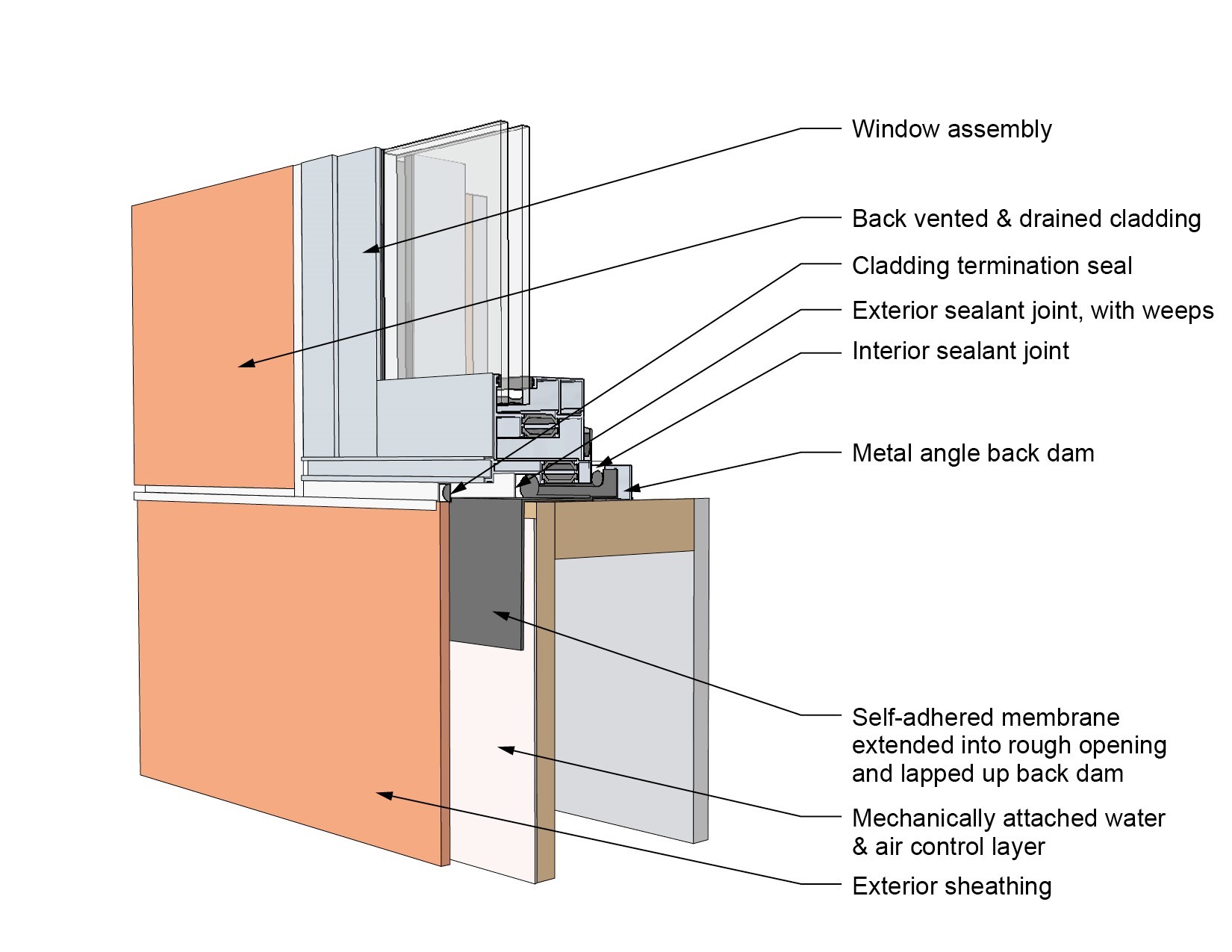
This drawing shows key head details for a window installation using a self-adhered membrane tape flashing on a wall with a mechanically attached water and air control layer
Image
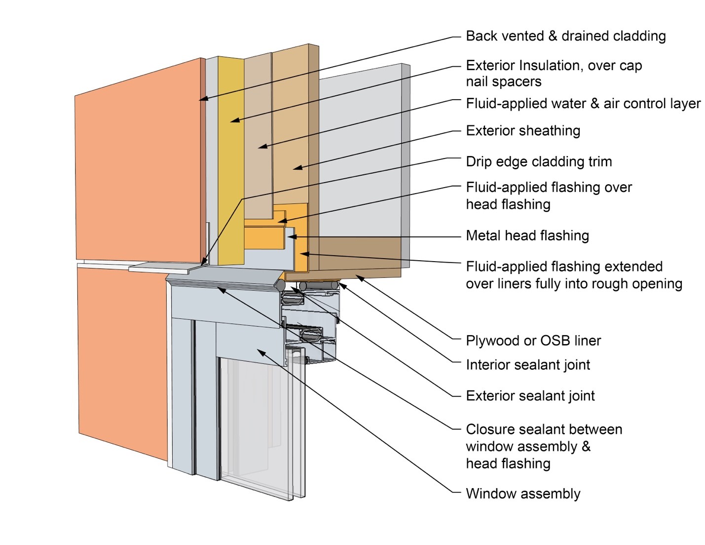
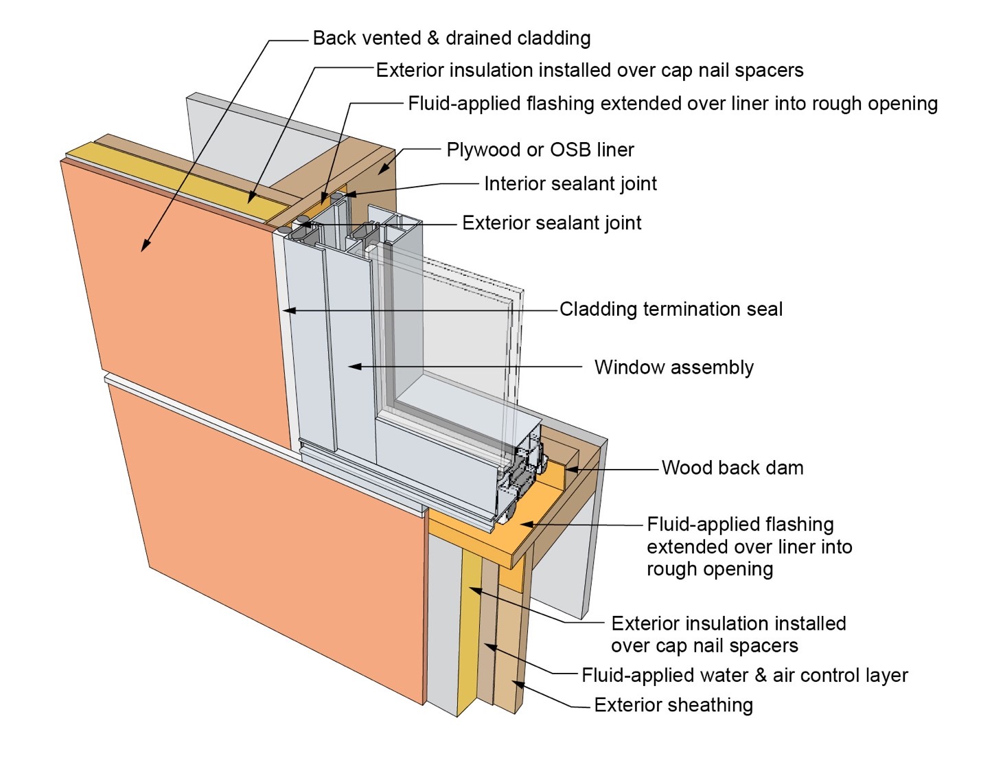
This drawing shows key head details for an “outie” window installation using a fluid-applied flashing on a wall with a fluid-applied water and air control layer and continuous insulation
Image
This drawing shows key jamb details for a window installation using a fluid-applied flashing on a wall with a fluid-applied water and air control layer
Image
This drawing shows key jamb details for a window installation using a fluid-applied flashing on a wall with a mechanically attached water and air control layer
Image
This drawing shows key jamb details for a window installation using a fluid-applied flashing on a wall with a mechanically attached water and air control layer and continuous insulation
Image
This drawing shows key jamb details for a window installation using a self-adhered membrane tape flashing on a wall with a mechanically attached water and air control layer
Image
This drawing shows key jamb details for an “outie” window installation using a fluid-applied flashing on a wall with a fluid-applied water and air control layer and continuous insulation
Image
This drawing shows key sill details for a window installation using a fluid-applied flashing on a wall with a fluid-applied water and air control layer
Image
This drawing shows key sill details for a window installation using a fluid-applied flashing on a wall with a mechanically attached water and air control layer
Image
This drawing shows key sill details for a window installation using a fluid-applied flashing on a wall with a mechanically attached water and air control layer and continuous insulation
Image
This drawing shows key sill details for a window installation using a self-adhered membrane tape flashing on a wall with a mechanically attached water and air control layer
Image
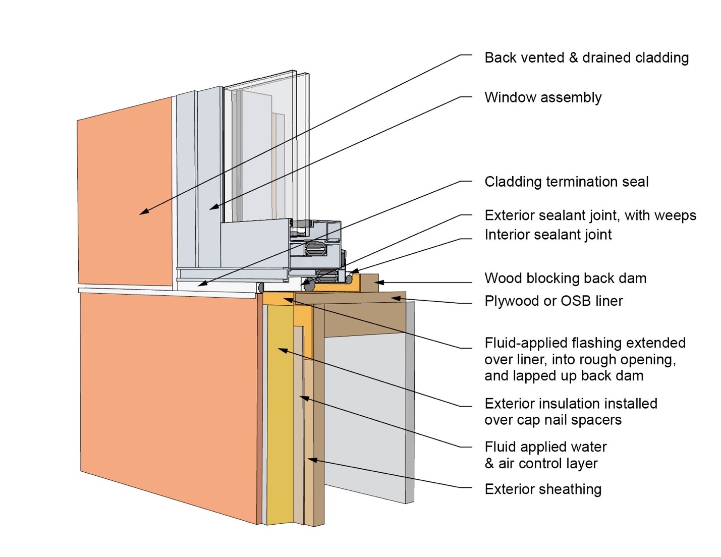
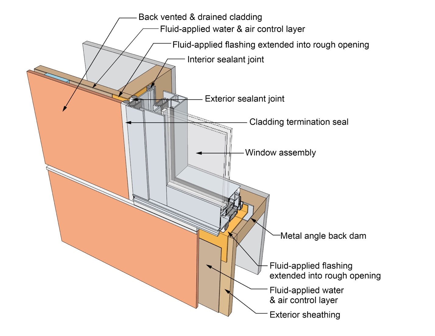
This drawing shows key sill details for an “outie” window installation using a fluid-applied flashing on a wall with a fluid-applied water and air control layer and continuous insulation
Image
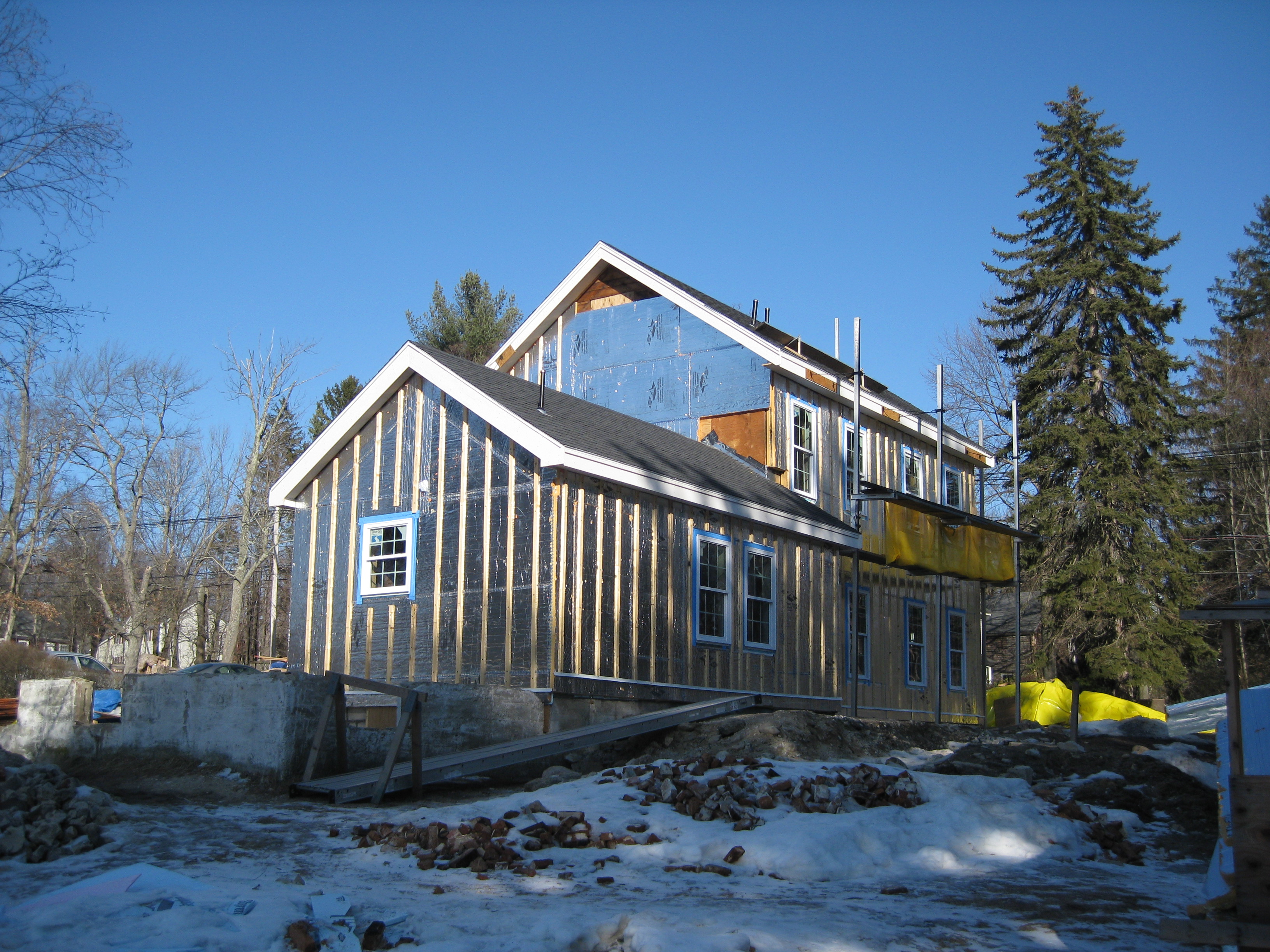
This farmhouse was retrofit by removing the existing siding and adding taped insulated sheathing and battens before installing new siding
Image
This house design in the Hot-Humid climate uses a slab foundation, masonry walls, and an Exterior Insulation Finish System (EIFS) cladding.
Image
Image
Windows are installed as “outies” in this wall assembly using a self-adhered membrane water and air control layer with continuous exterior insulation
Image
Image

Image
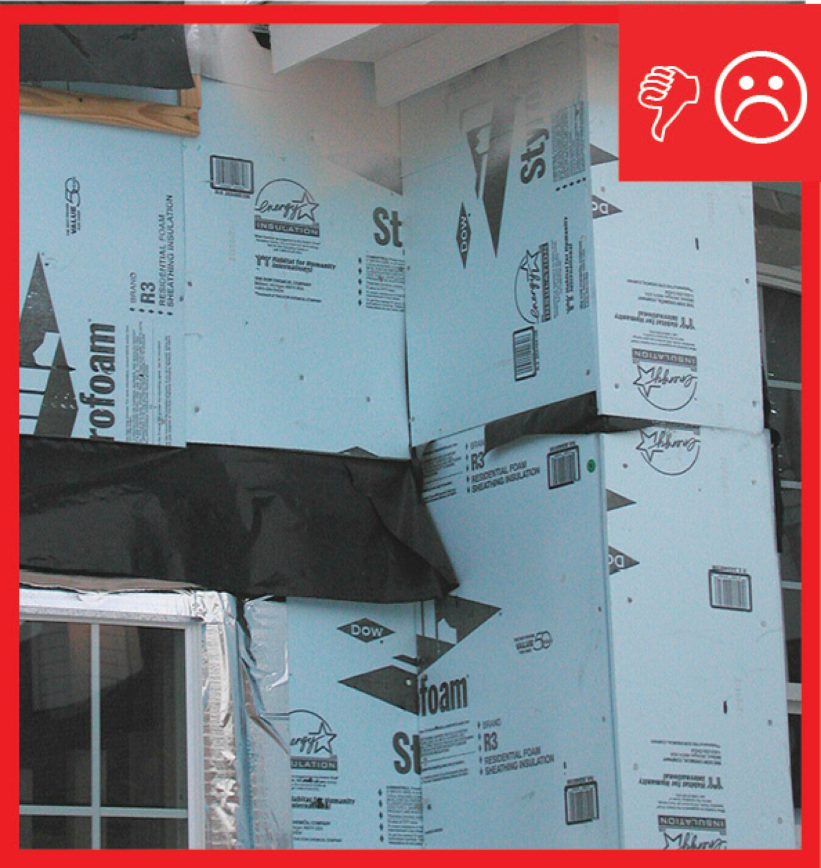
Wrong – The rigid sheathing seams are not taped and the gaps could cause moisture problems
Image
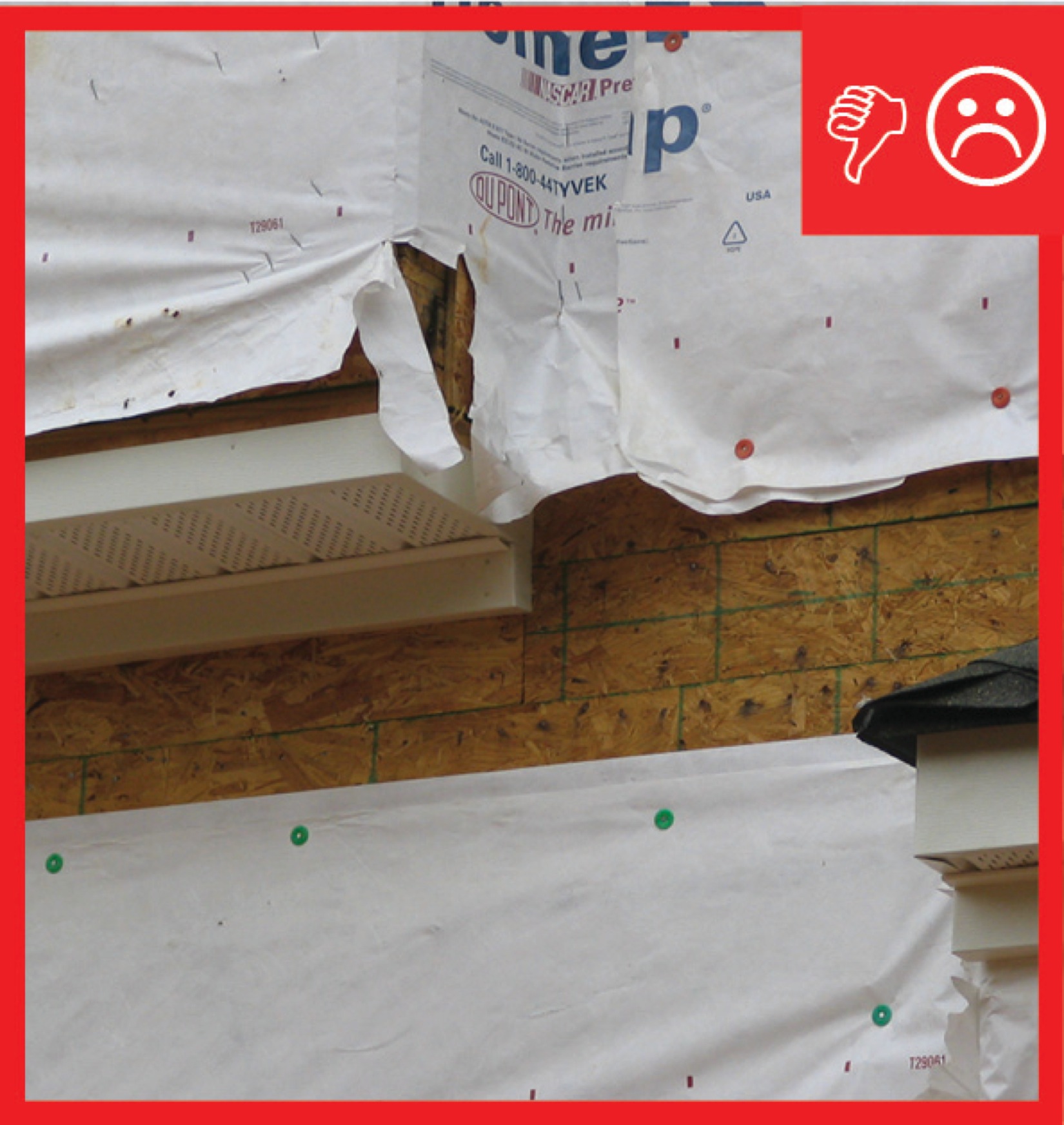
Wrong – The water-resistant barrier is not complete and the holes and gaps could cause moisture problems
Image

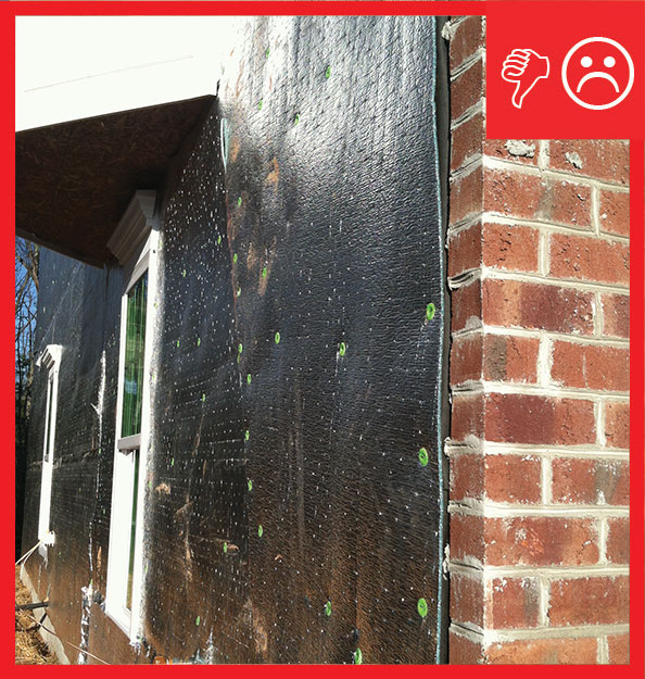
Wrong – There is not a water-resistant barrier installed underneath the exterior finish of the walls