Showing results 501 - 550 of 688
Image
The water-resistant barrier, weep screed, and stucco lathe are properly layered and will create a complete drainage system
Image
Image
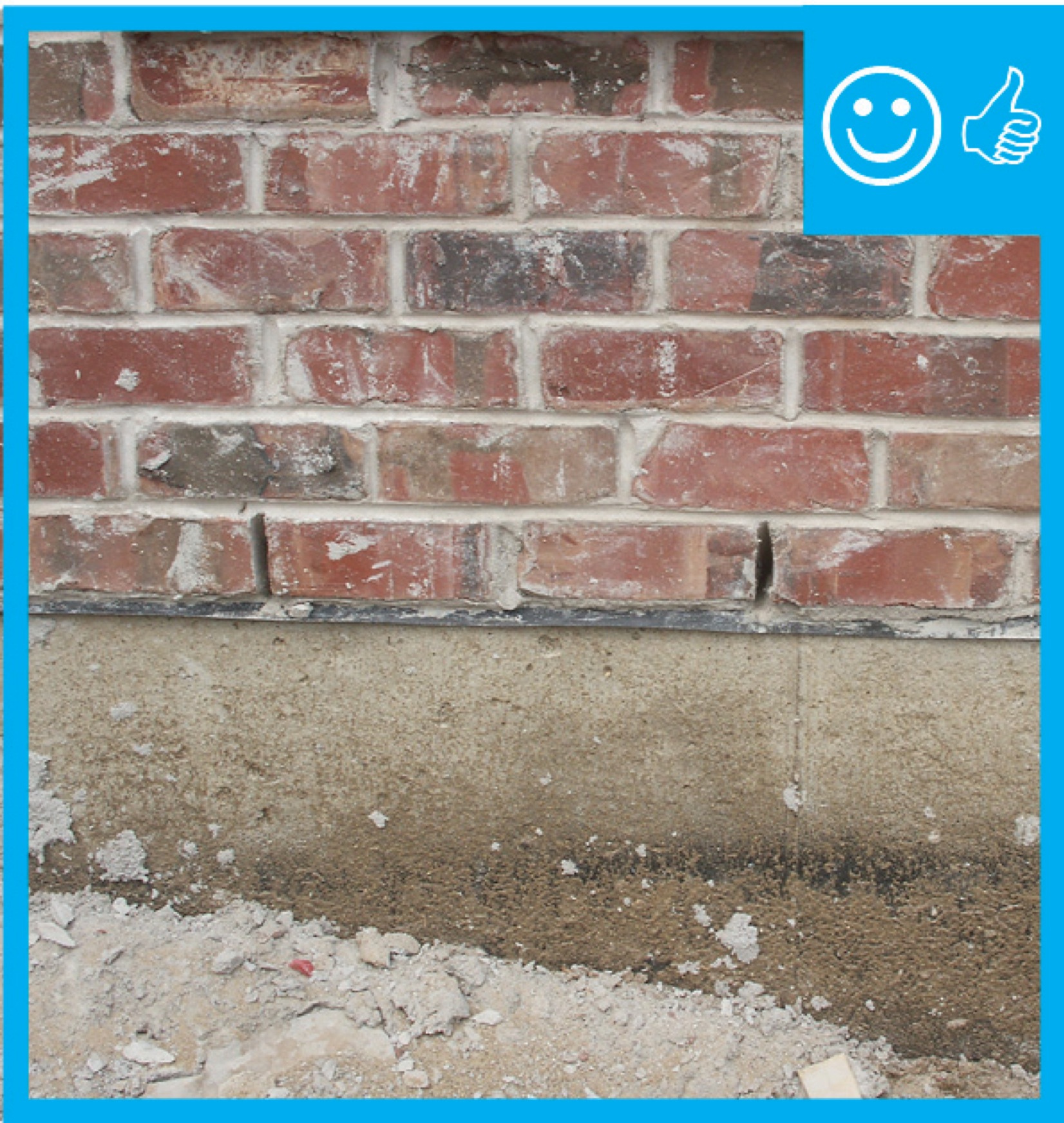
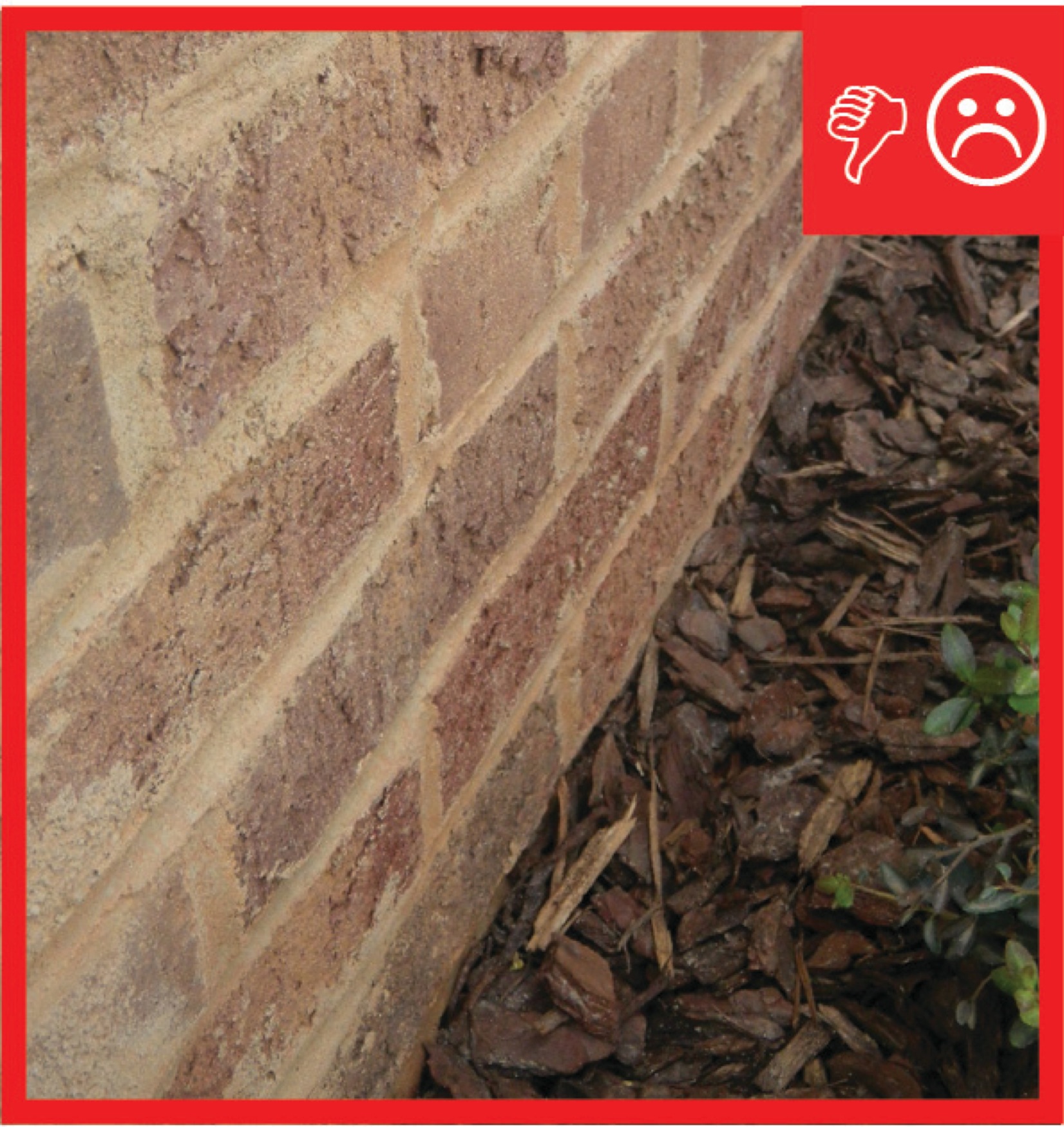
The weep holes are spaced at the correct distance to provide a complete drainage system
Image

Image
Image

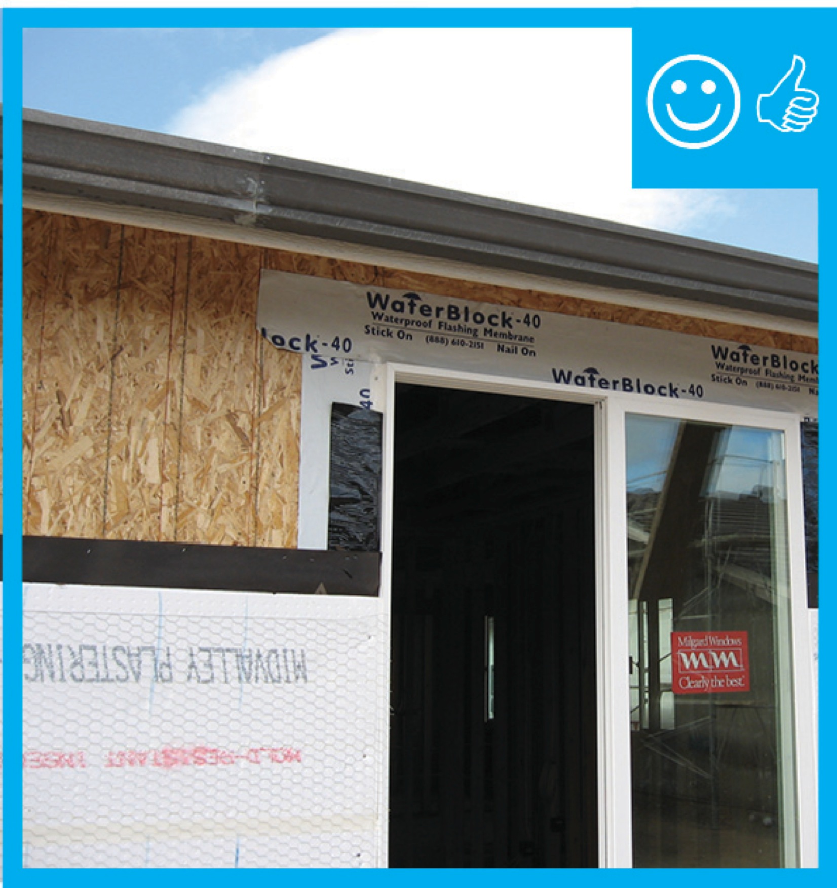
The windows in this building are connected to the fully adhered water and air control layer using fluid-applied flashing
Image
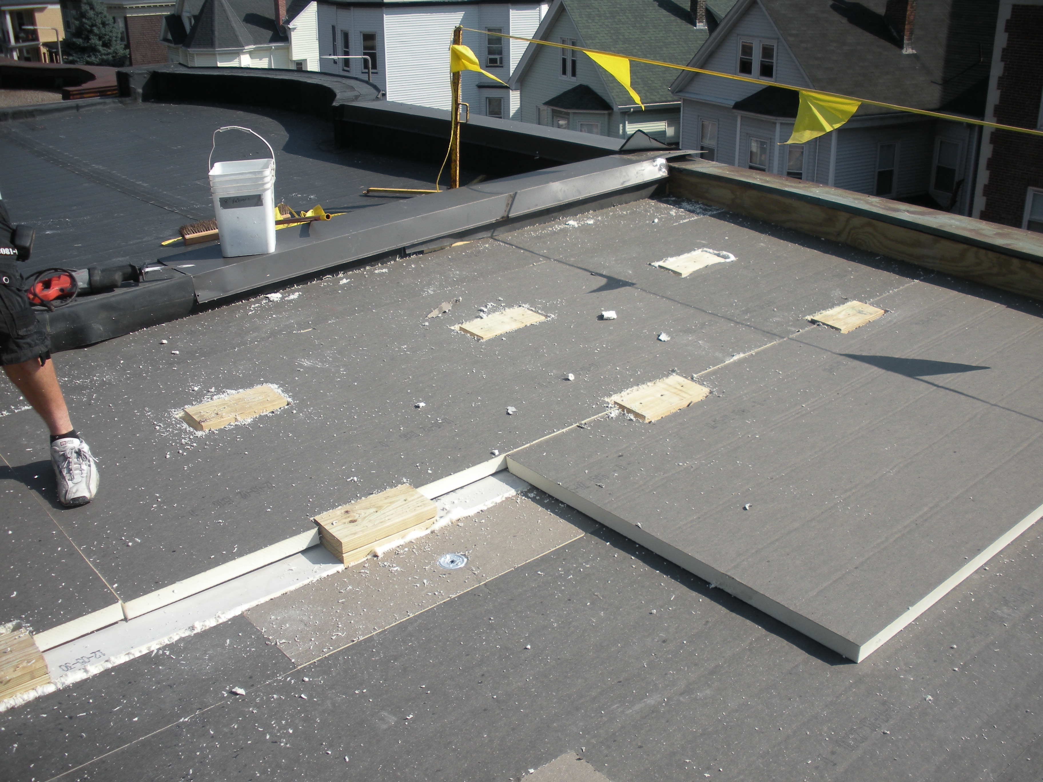
The wood blocking for future PV panel installation extends above the surface of the top layer of polyisocyanurate rigid foam insulation installed as part of a flat roof retrofit
Image
Image
Image
Image
Image
Image
Image
Image
Image
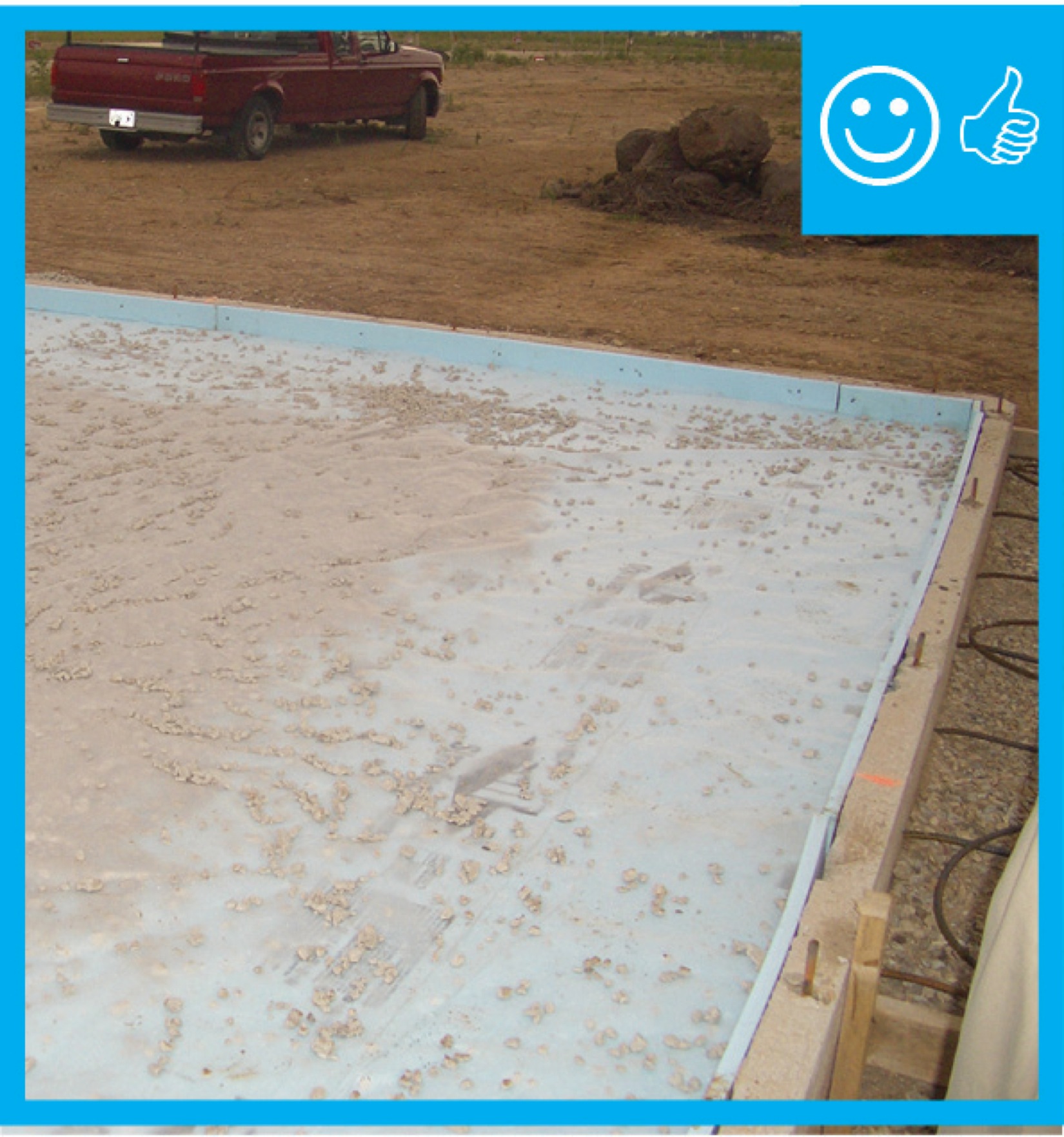
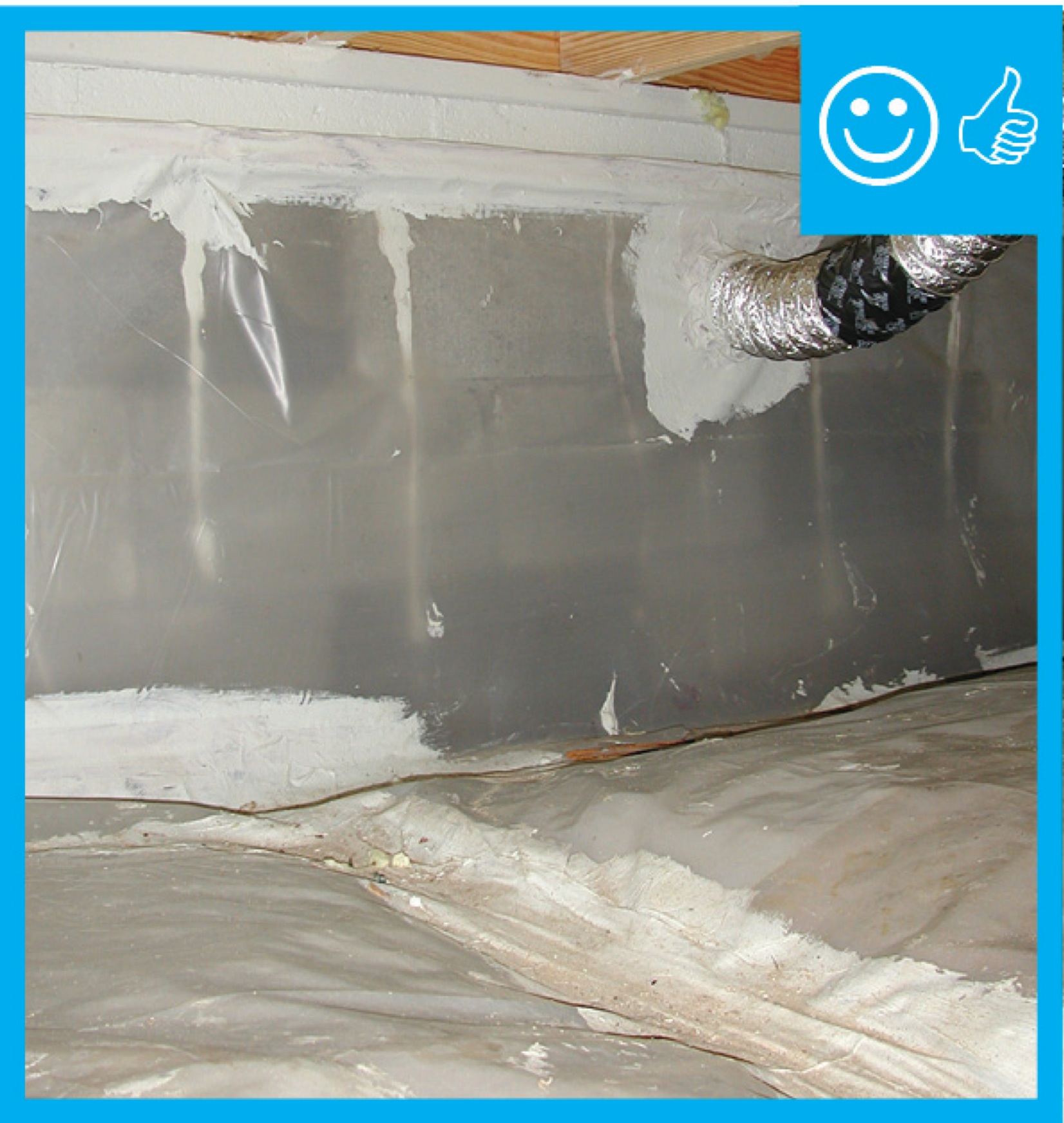
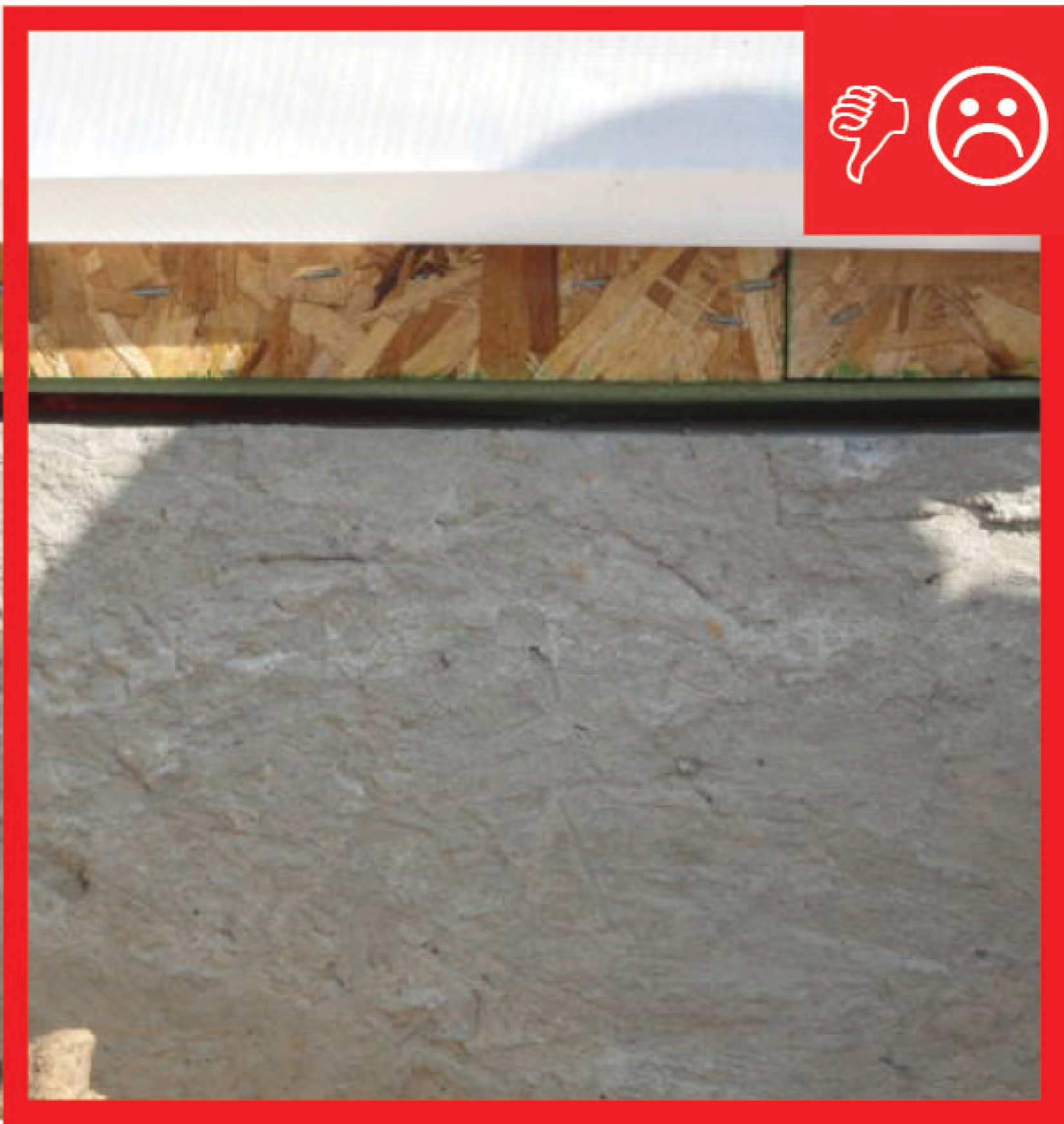
There is polyethylene sheeting installed to provide a capillary break between the ground and slab
Image
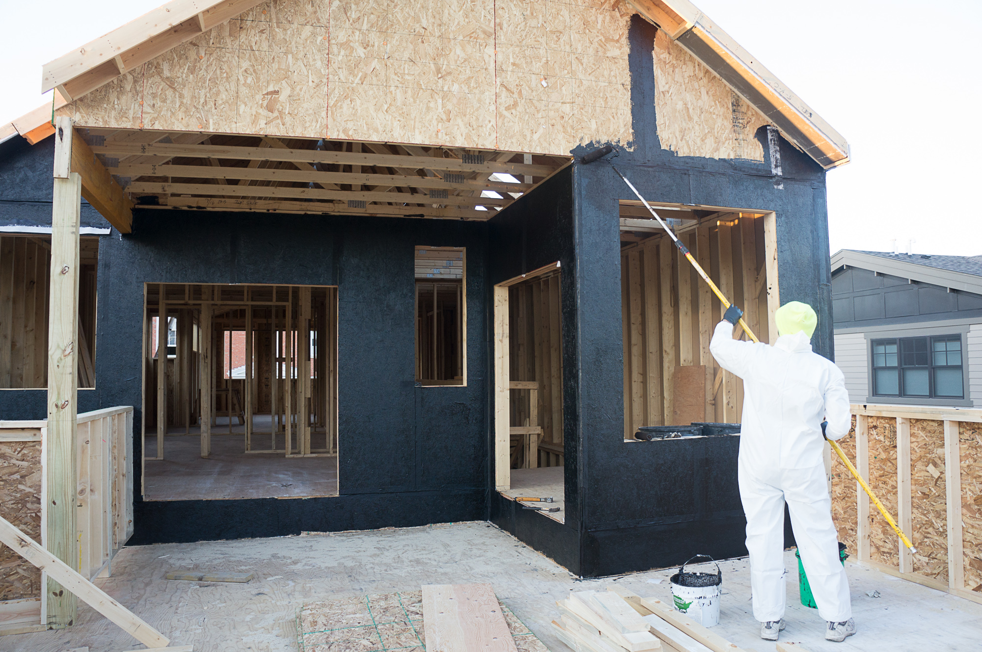
This asphalt-based, vapor-permeable coating is painted directly onto the OSB sheathing to provide a weather-resistant barrier that also reduces air leakage.
Image

This builder employs good water runoff managementpractices to control sediment during construction and to ensure that stormwater drains away from the house after construction.
Image
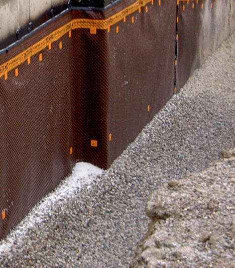
This building foundation has a drainage layer located on the exterior of the waterproofing membrane.
Image
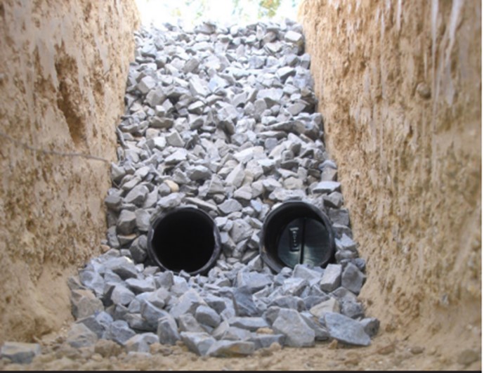
This double French drain provides drainage for a significant volume of storm water.
Image
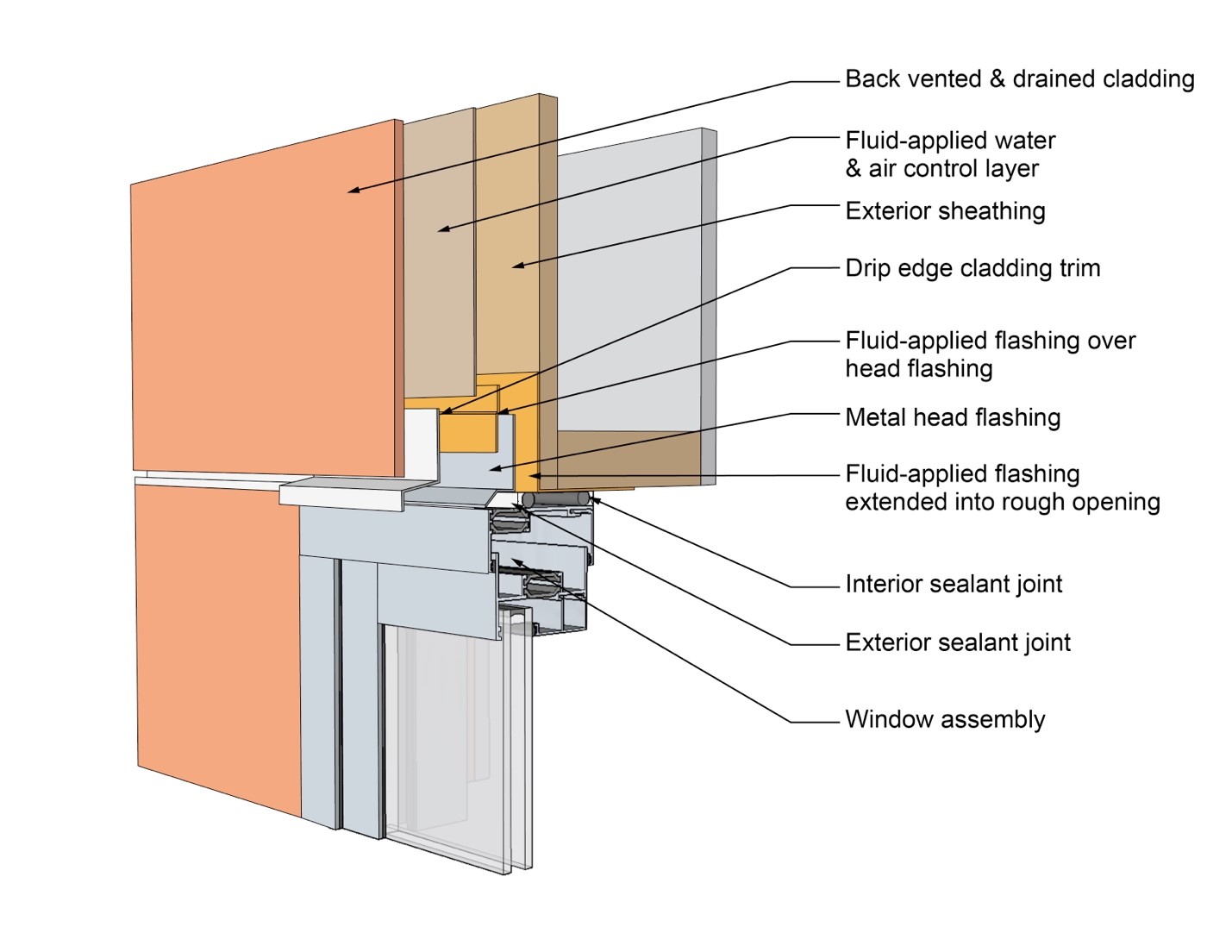
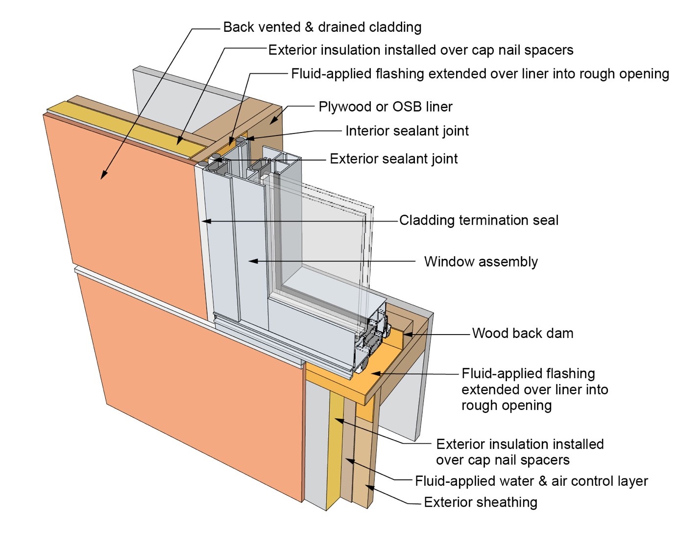
This drawing shows key head details for a window installation using a fluid-applied flashing on a wall with a fluid-applied water and air control layer
Image
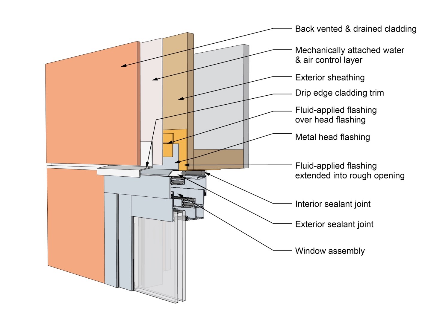
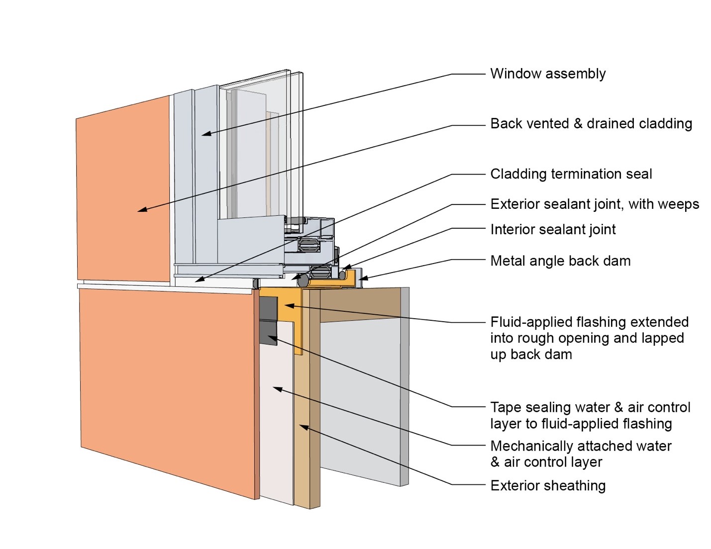
This drawing shows key head details for a window installation using a fluid-applied flashing on a wall with a mechanically attached water and air control layer
Image
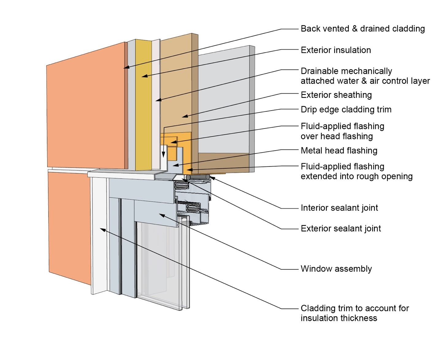
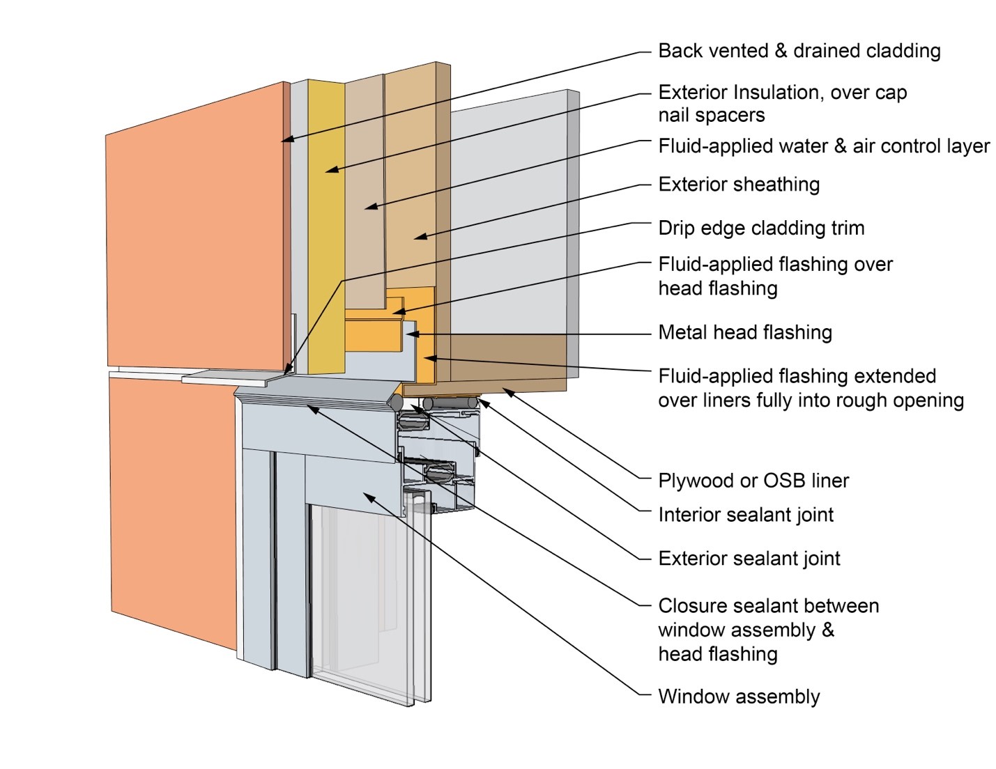
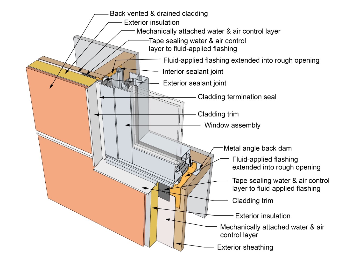
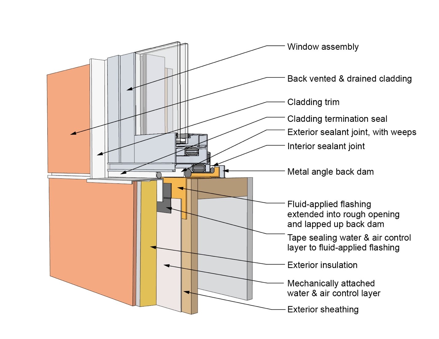
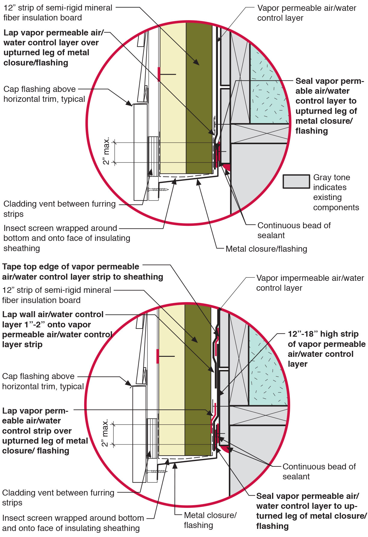
This drawing shows key head details for a window installation using a fluid-applied flashing on a wall with a mechanically attached water and air control layer and continuous insulation
Image
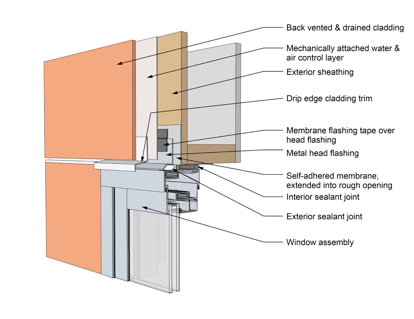
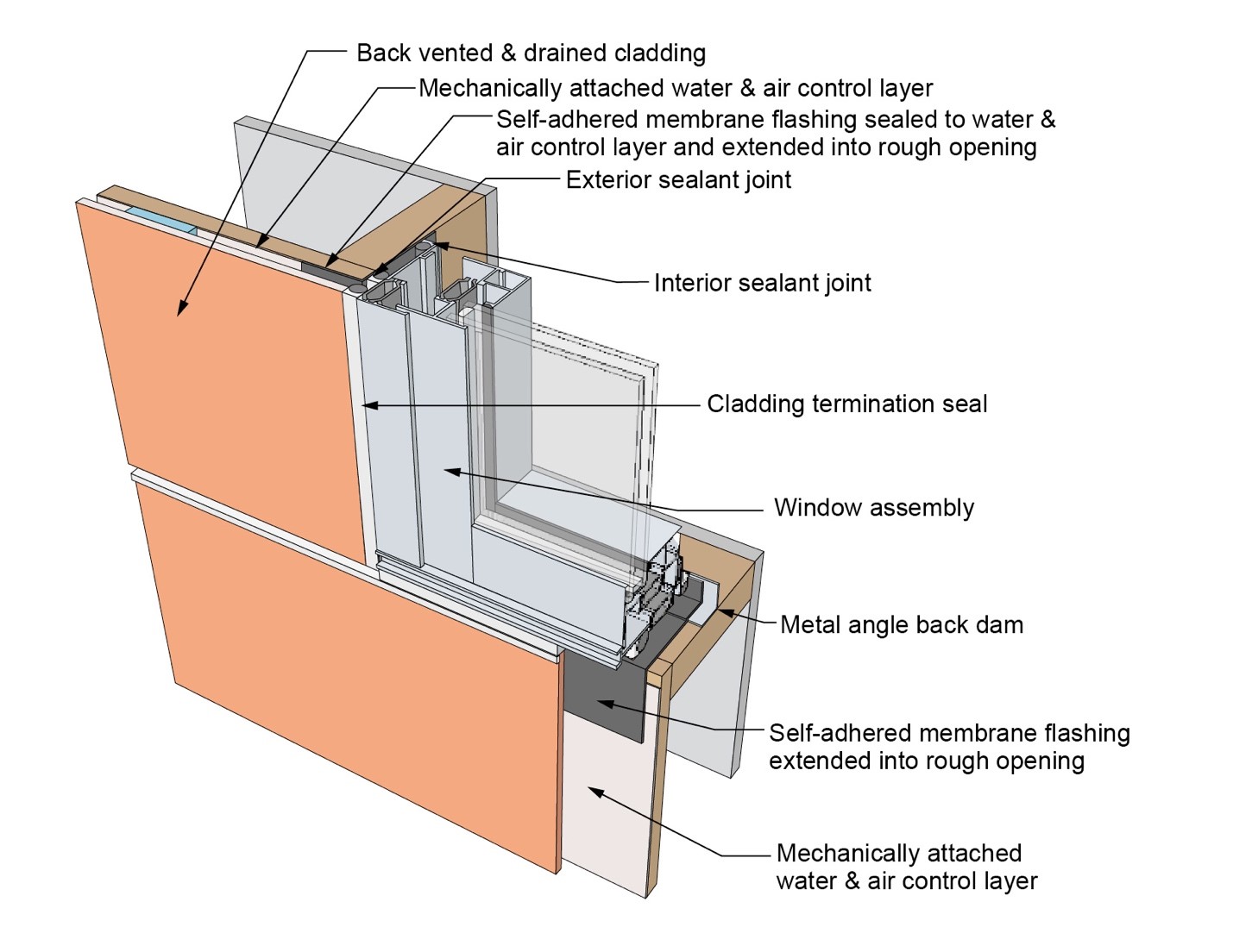
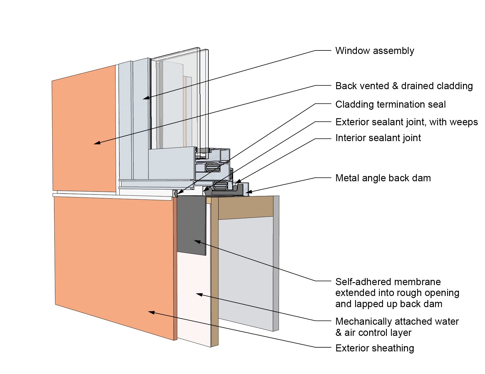
This drawing shows key head details for a window installation using a self-adhered membrane tape flashing on a wall with a mechanically attached water and air control layer
Image
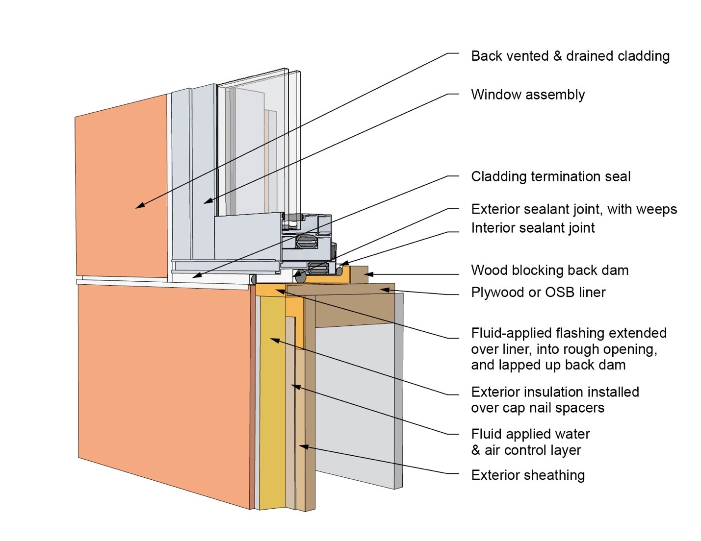
This drawing shows key head details for an “outie” window installation using a fluid-applied flashing on a wall with a fluid-applied water and air control layer and continuous insulation
Image
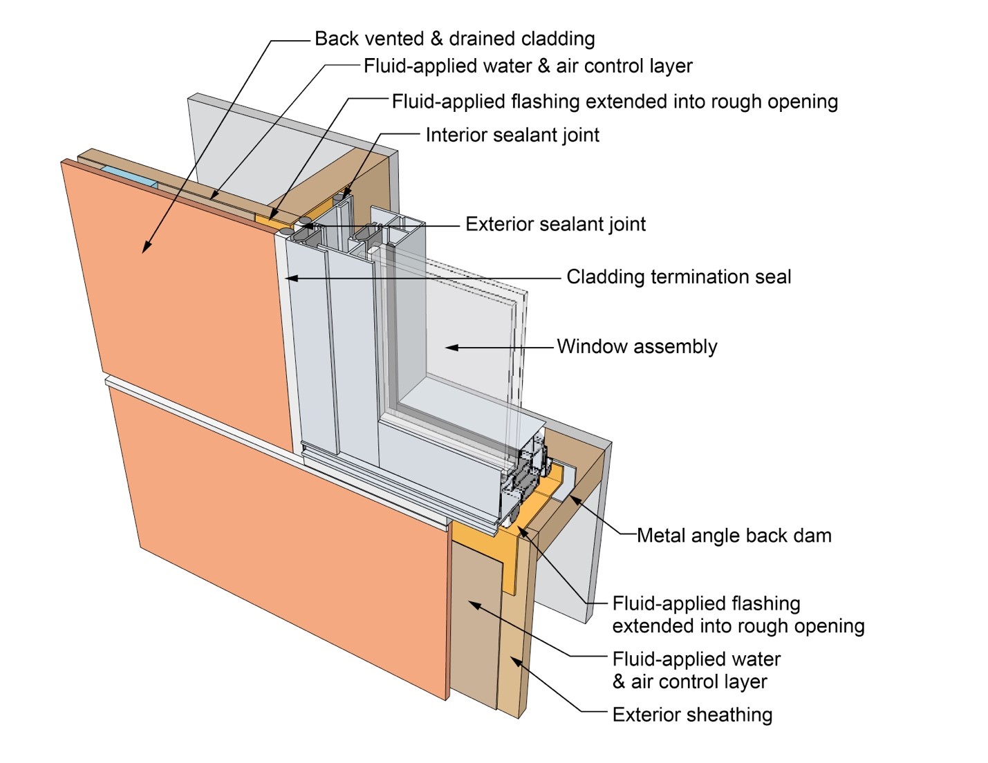
This drawing shows key jamb details for a window installation using a fluid-applied flashing on a wall with a fluid-applied water and air control layer
Image
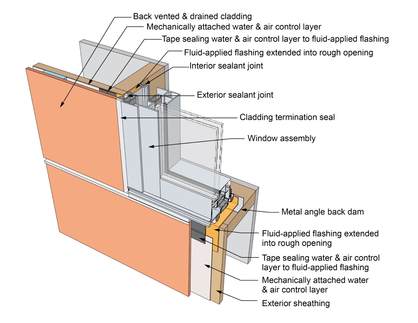
This drawing shows key jamb details for a window installation using a fluid-applied flashing on a wall with a mechanically attached water and air control layer
Image
This drawing shows key jamb details for a window installation using a fluid-applied flashing on a wall with a mechanically attached water and air control layer and continuous insulation
Image
This drawing shows key jamb details for a window installation using a self-adhered membrane tape flashing on a wall with a mechanically attached water and air control layer
Image
This drawing shows key jamb details for an “outie” window installation using a fluid-applied flashing on a wall with a fluid-applied water and air control layer and continuous insulation
Image
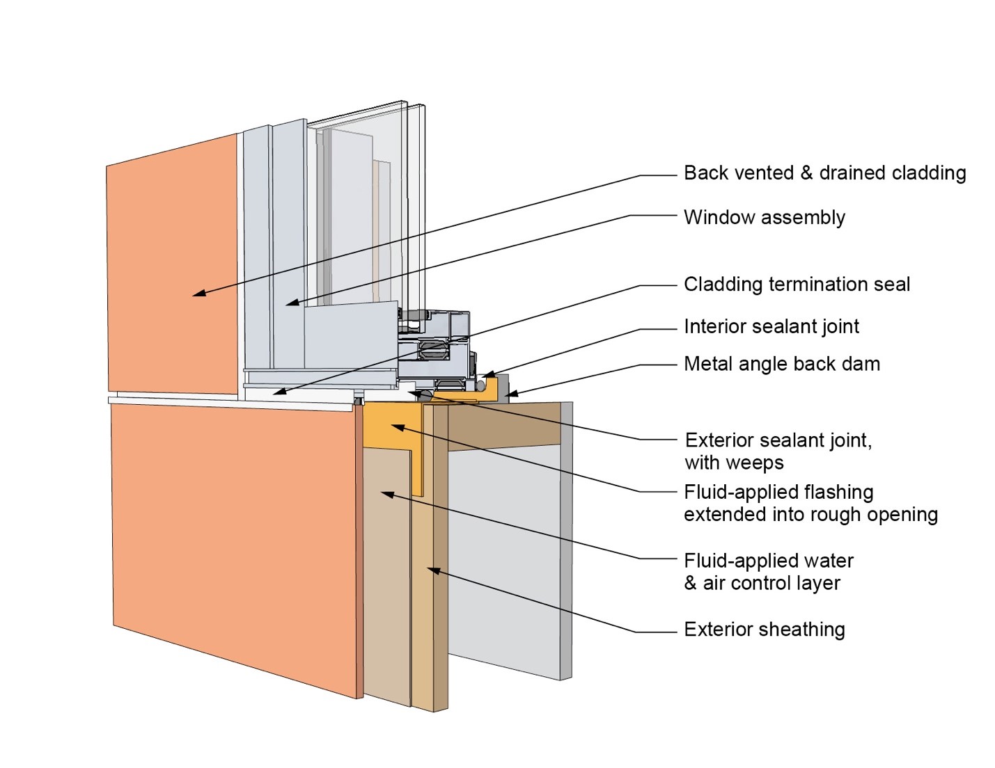
This drawing shows key sill details for a window installation using a fluid-applied flashing on a wall with a fluid-applied water and air control layer
Image
This drawing shows key sill details for a window installation using a fluid-applied flashing on a wall with a mechanically attached water and air control layer
Image
This drawing shows key sill details for a window installation using a fluid-applied flashing on a wall with a mechanically attached water and air control layer and continuous insulation
Image
This drawing shows key sill details for a window installation using a self-adhered membrane tape flashing on a wall with a mechanically attached water and air control layer
Image
This drawing shows key sill details for an “outie” window installation using a fluid-applied flashing on a wall with a fluid-applied water and air control layer and continuous insulation
Image
This exterior wall retrofit permits drying to the exterior of a sill plate installed on an untreated flat foundation wall
Image
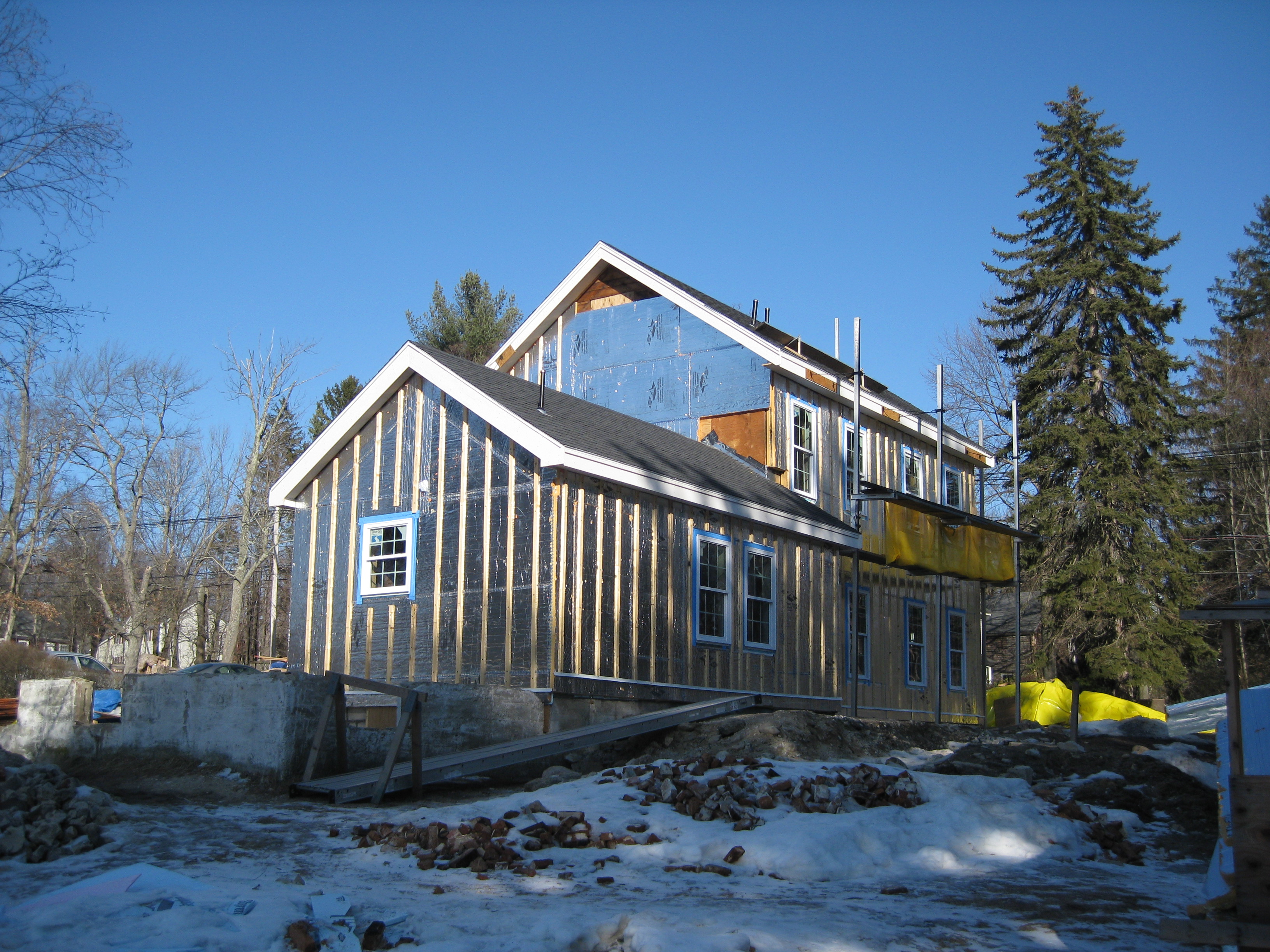
This farmhouse was retrofit by removing the existing siding and adding taped insulated sheathing and battens before installing new siding
Image
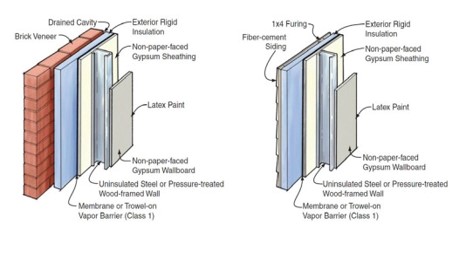
This flood-resistant exterior wall with brick or fiber-cement siding will limit moisture damage in exterior walls.
Image
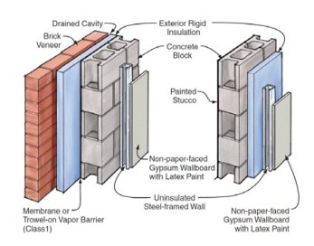
This flood-resistant masonry wall design with metal framing and rigid foam insulation will limit moisture damage in exterior walls.
Image

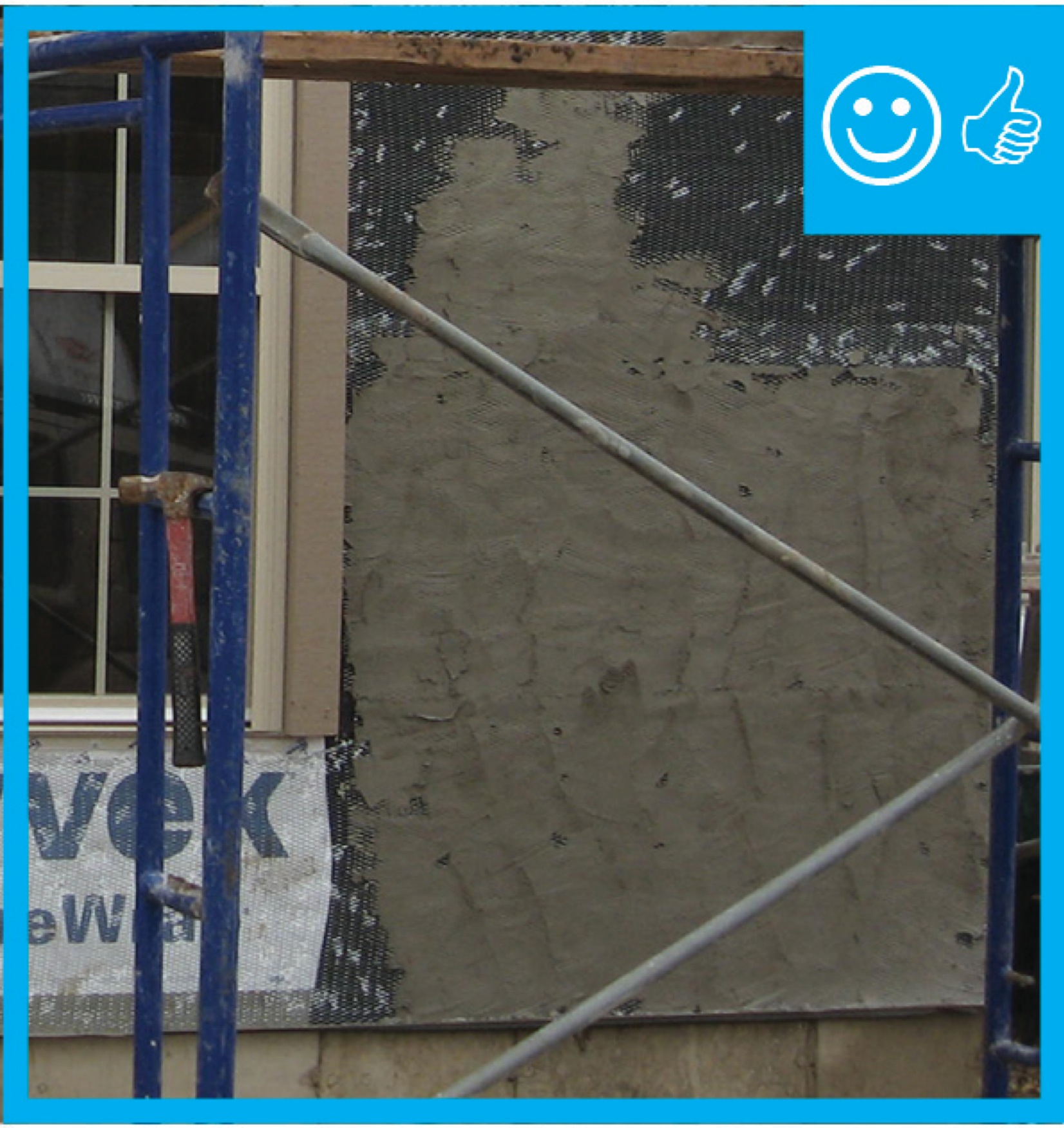
This home is covered with coated sheathing. Wall portions that will be covered with stone have a dimple plastic moisture barrier and metal lathe that is being covered with plaster.
Image

This home was designed with continuous roof vents and few roof penetrations, allowing more room for the solar shingles that integrate with the asphalt shingles installed to meet IBHS Fortified Roof criteria for increased resistance to high winds and rain
Image
This house design in the Hot-Humid climate uses a slab foundation, masonry walls, and an Exterior Insulation Finish System (EIFS) cladding.
Image
Image
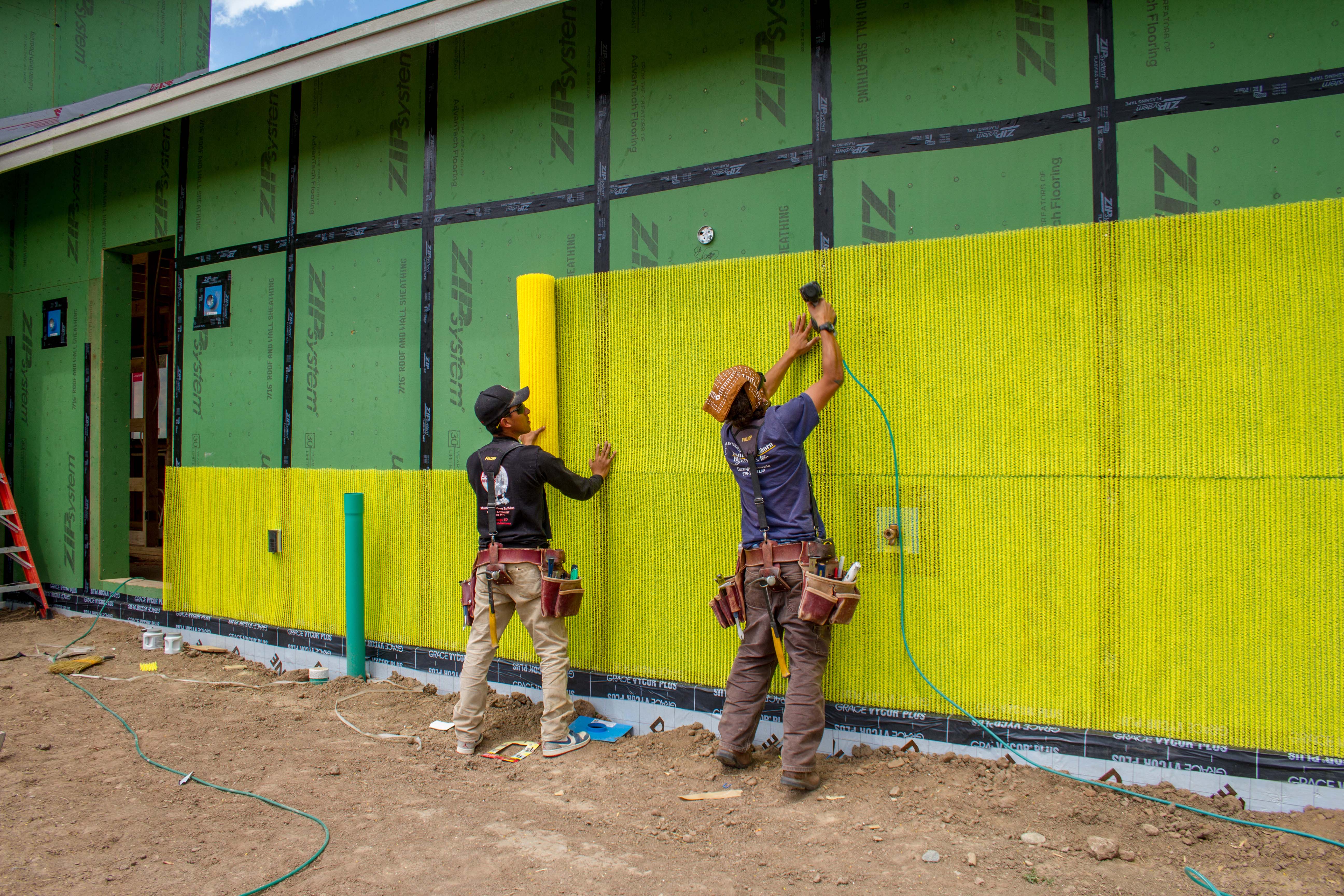
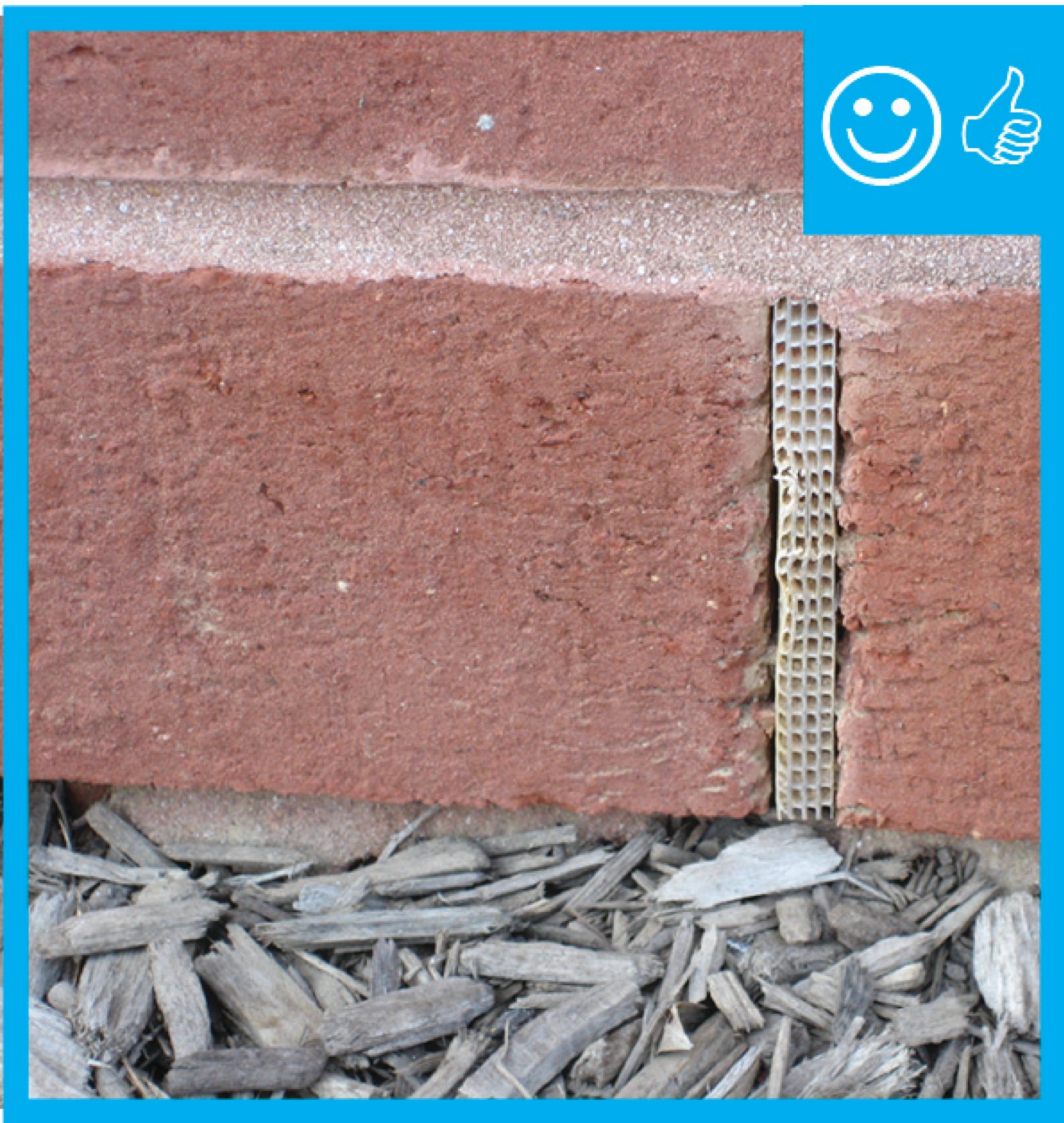
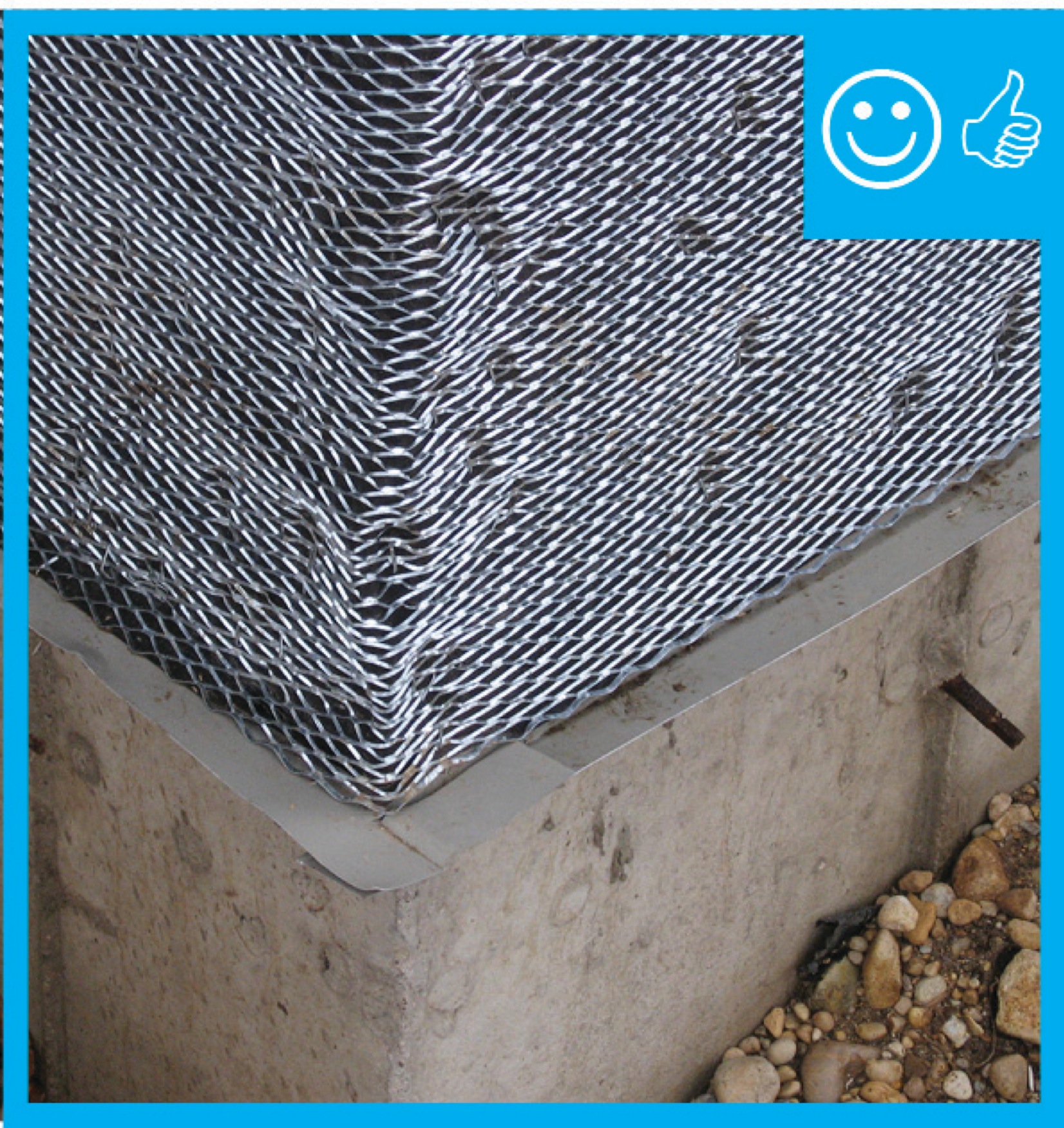
This plastic mesh material creates an air space behind the siding and provides a route for water to run out of the wall in case of leaks.
Image
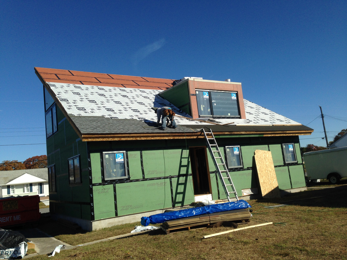
This roof is hurricane proofed with a coated insulated OSB deck sheathing that is caulked and taped at all seams with a water-resistant tape, then fully covered with a peel-and-stick membrane, and asphalt shingles.
Image
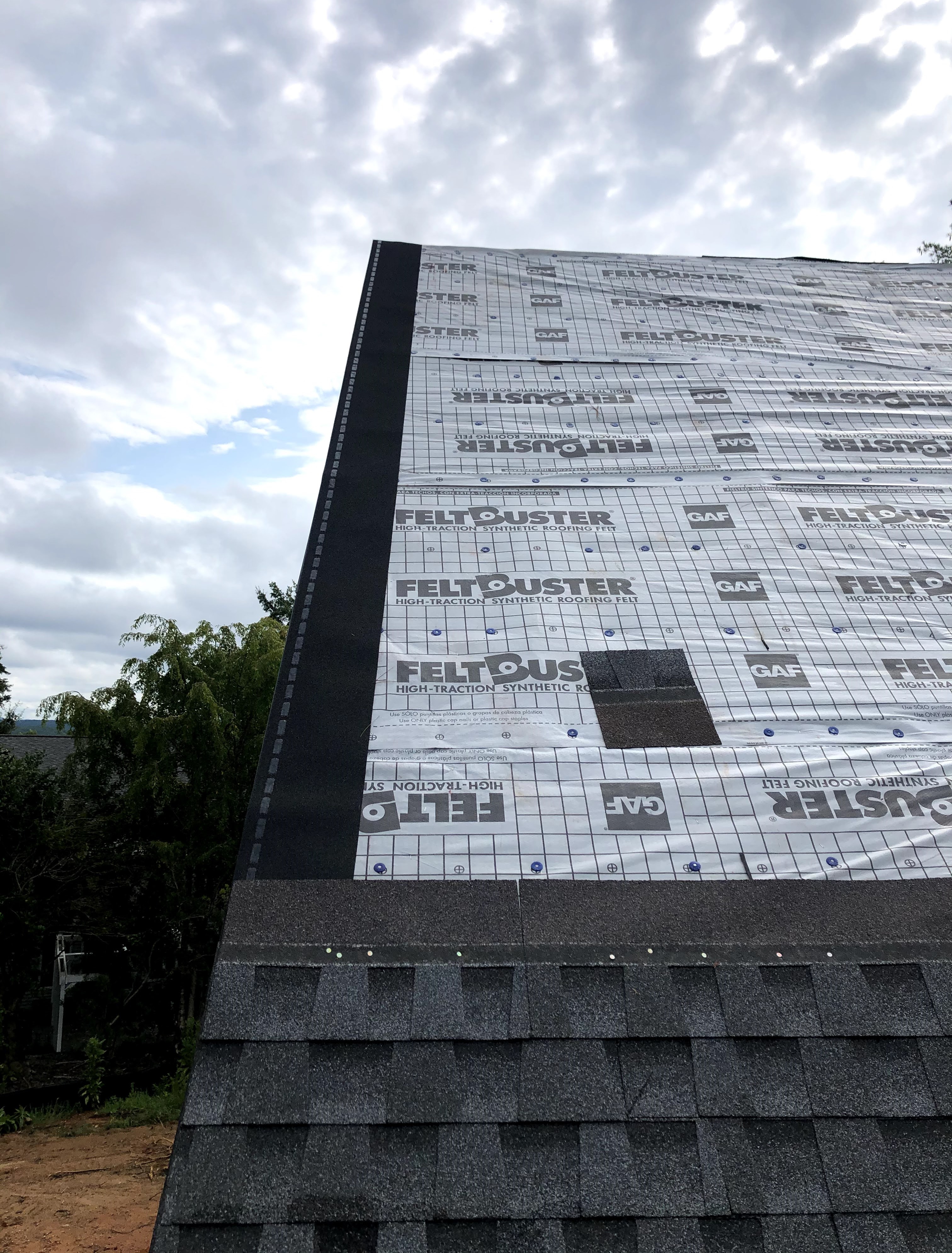
This roof was constructed to meet the IBHS Fortified Roof standard by sealing the decking seams with flashing tape, installing synthetic roof underlayment secured with metal drip edge and nailed every six inches, and using self-adhered starter shingles.
Image
Image
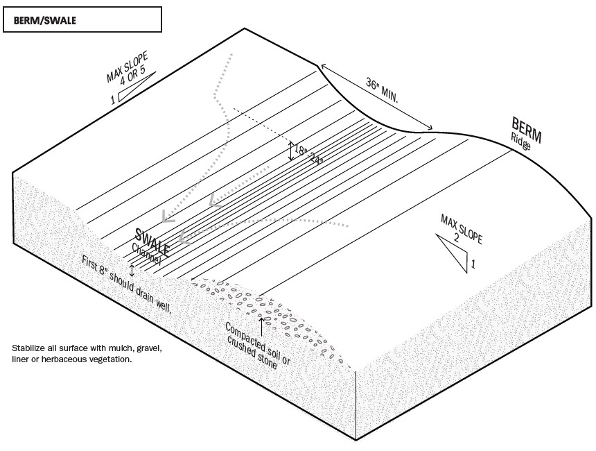
This swale and berm slow the flow of stormwater across a site to minimize erosion.
Image

Image

Threaded connections are one source of leaks in showerheads and showerhead arms.