Showing results 51 - 100 of 133
Image
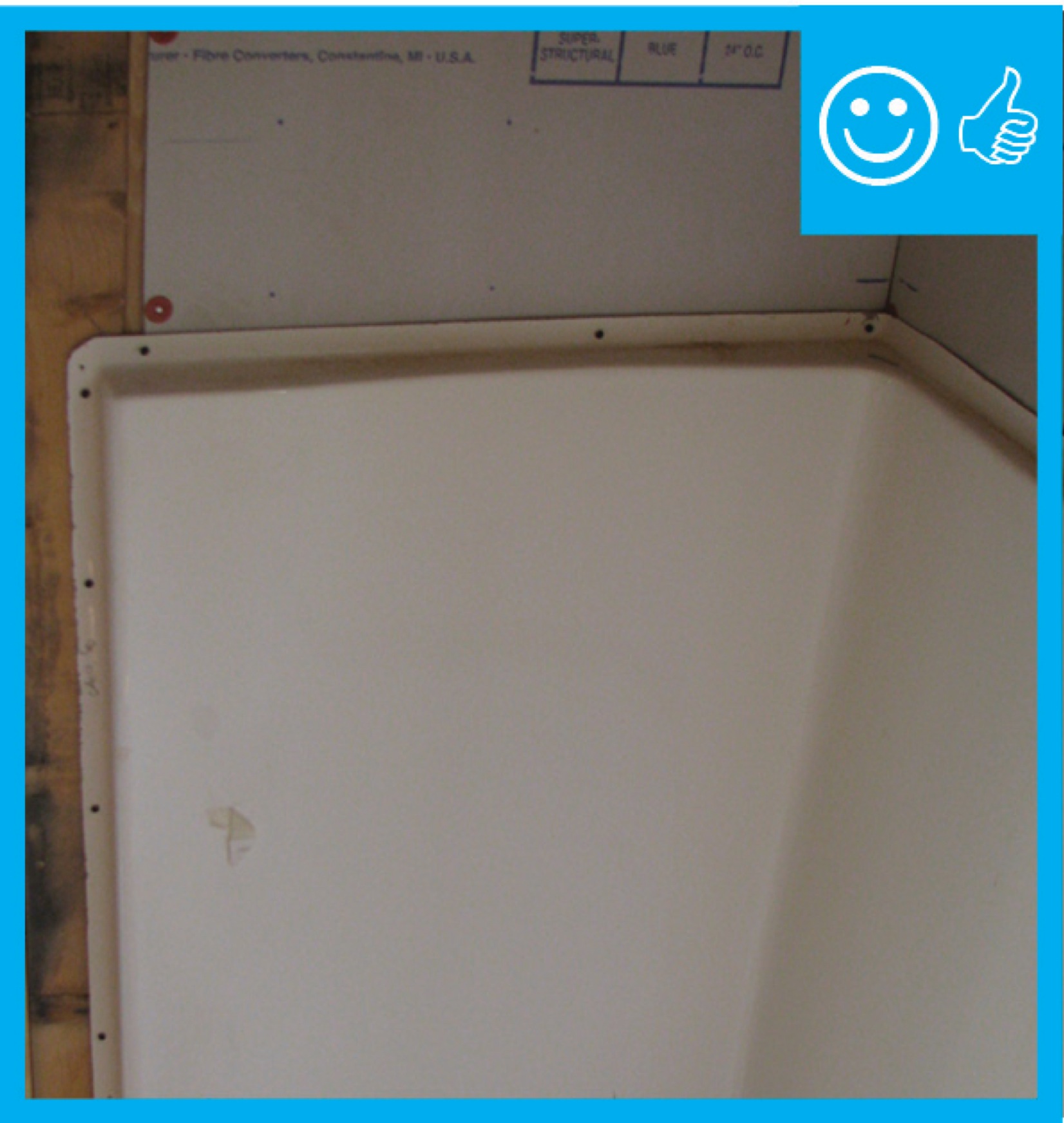
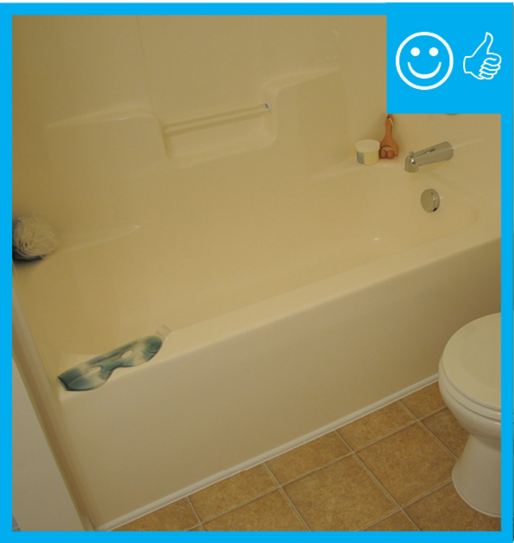
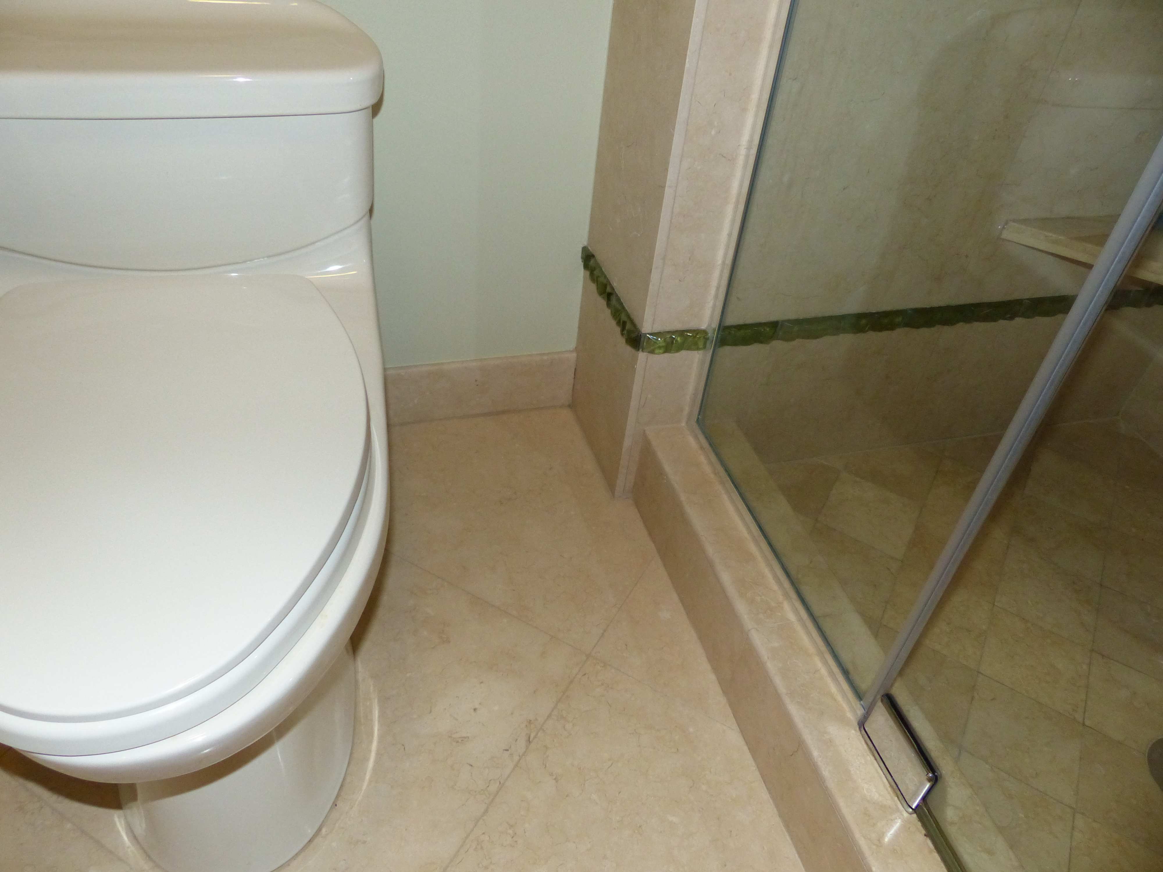
Right – Moisture-resistant backing material has been used above and behind the tub enclosure.
Image
Image
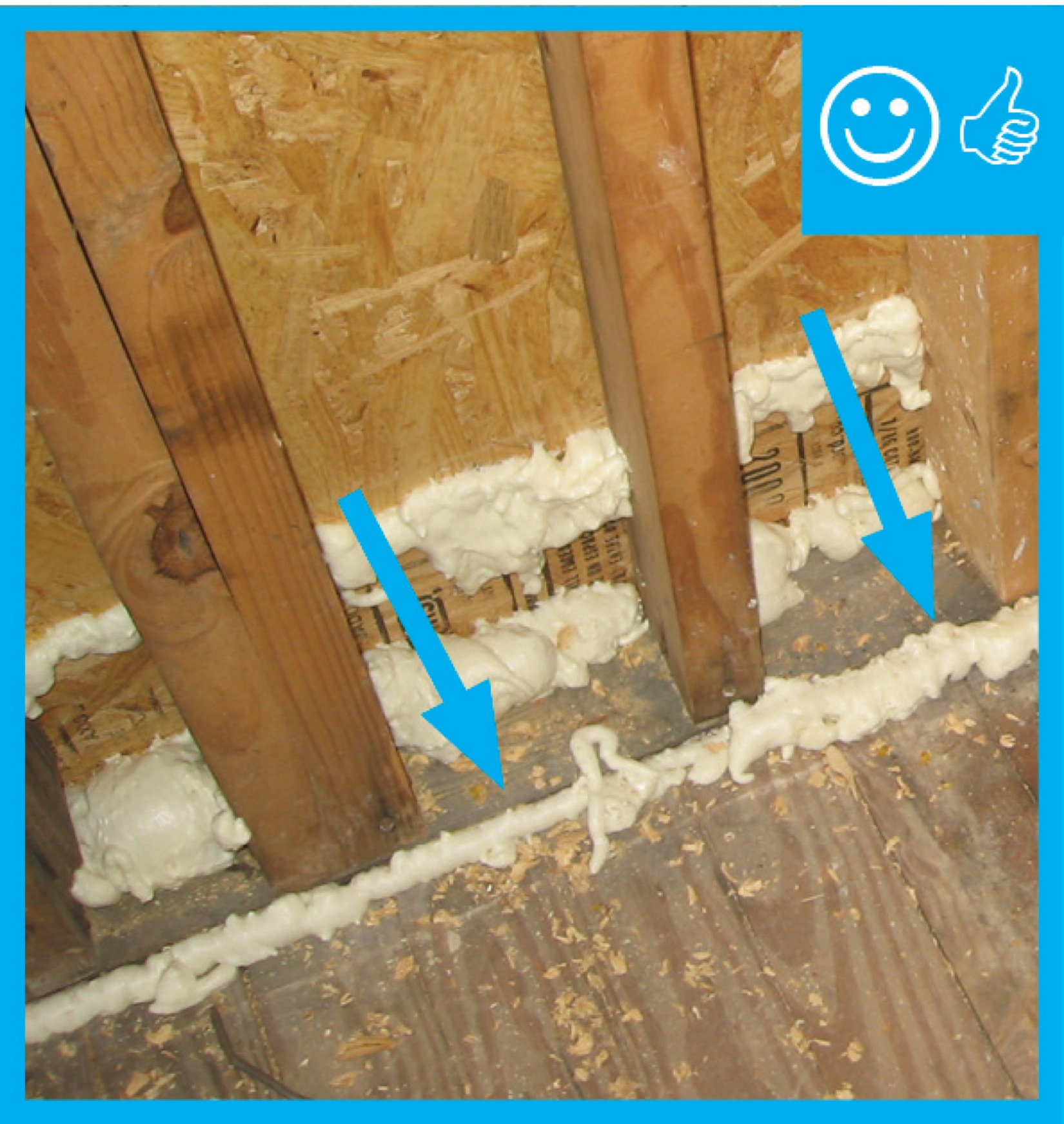
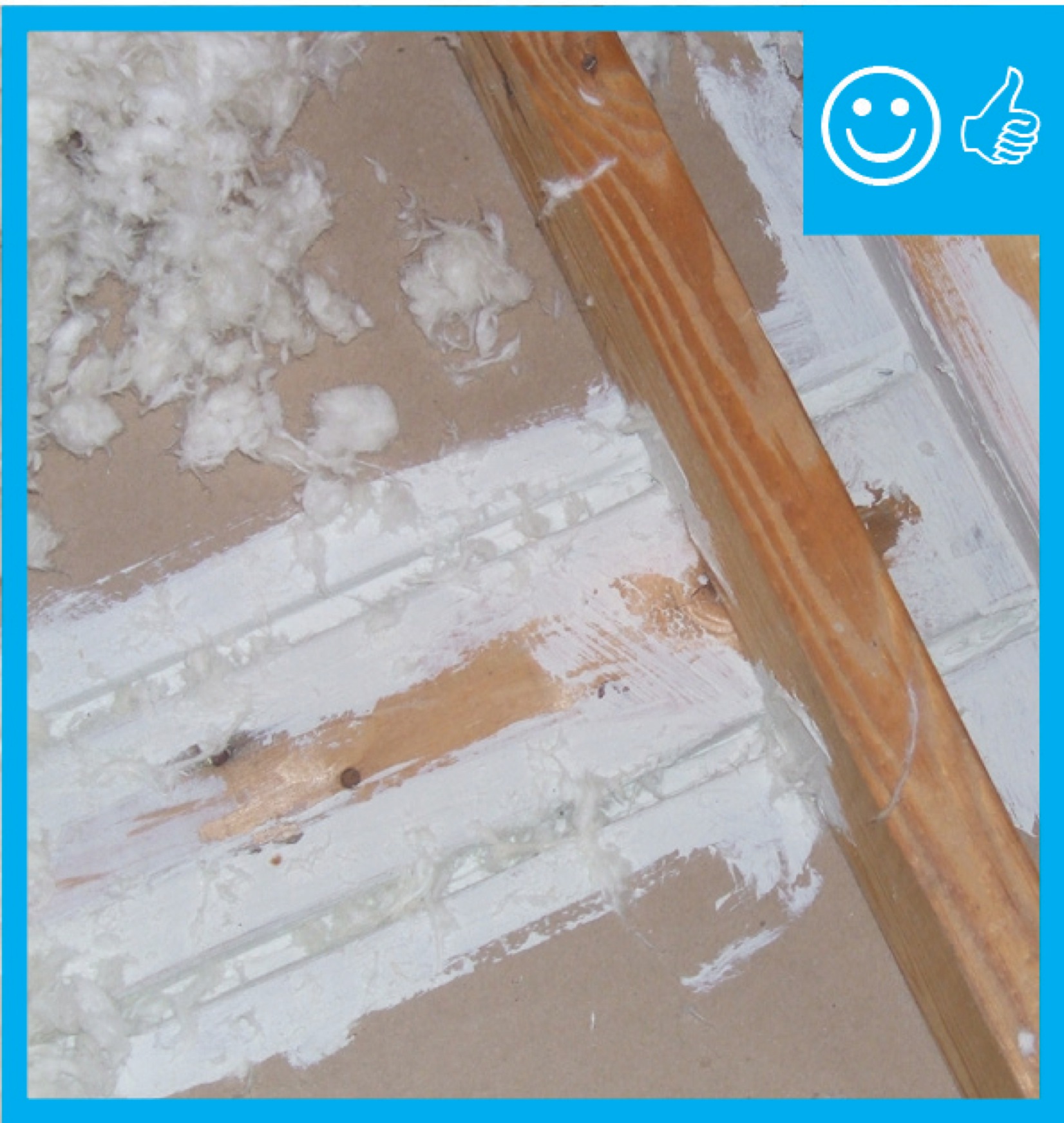
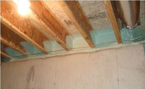
Right – Spray foam was installed at the sheathing intersection as well as the sill plate to sub-floor connection.
Image
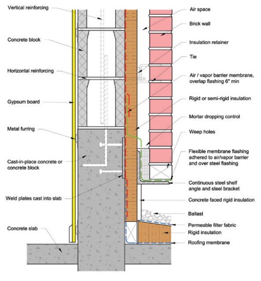
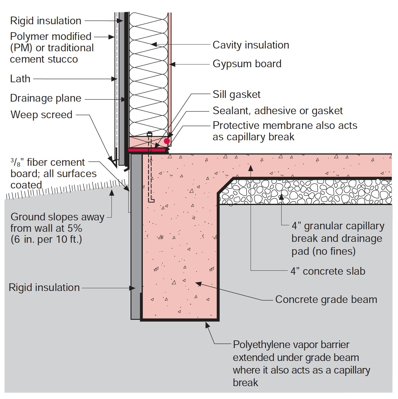
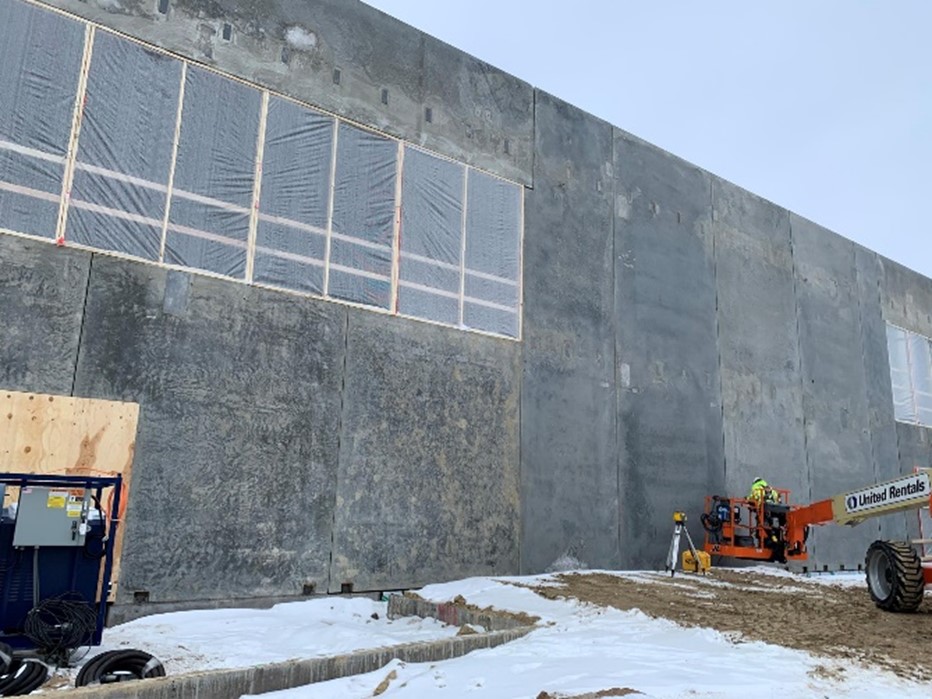
Right – The insulation has been located to the exterior of the thermal mass in this wall section
Image
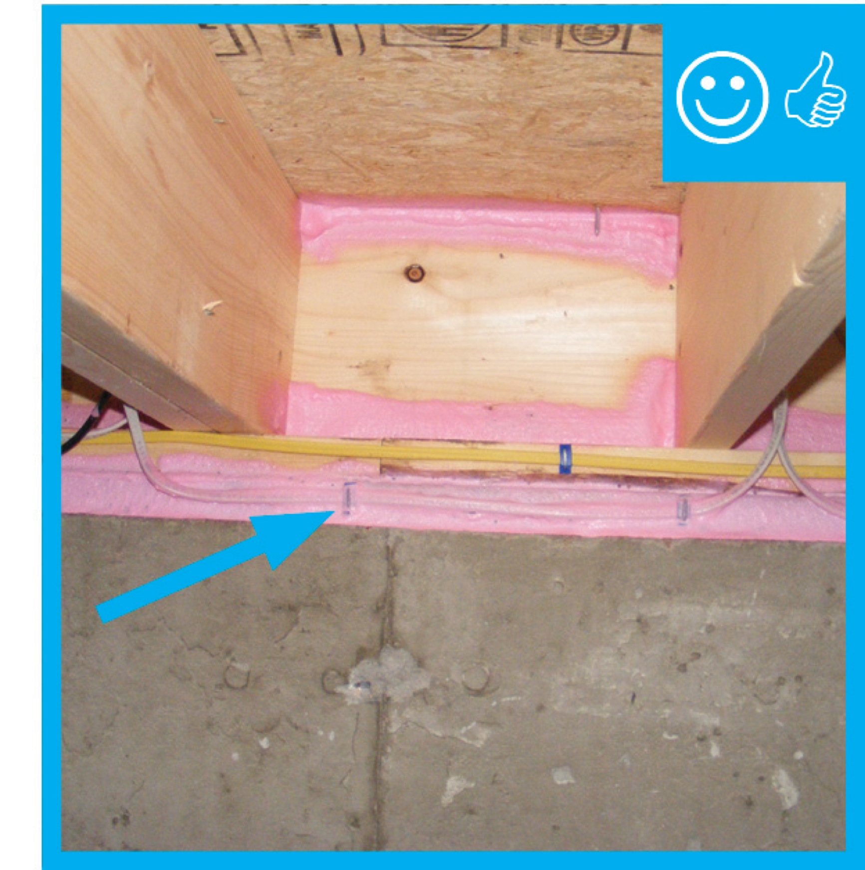
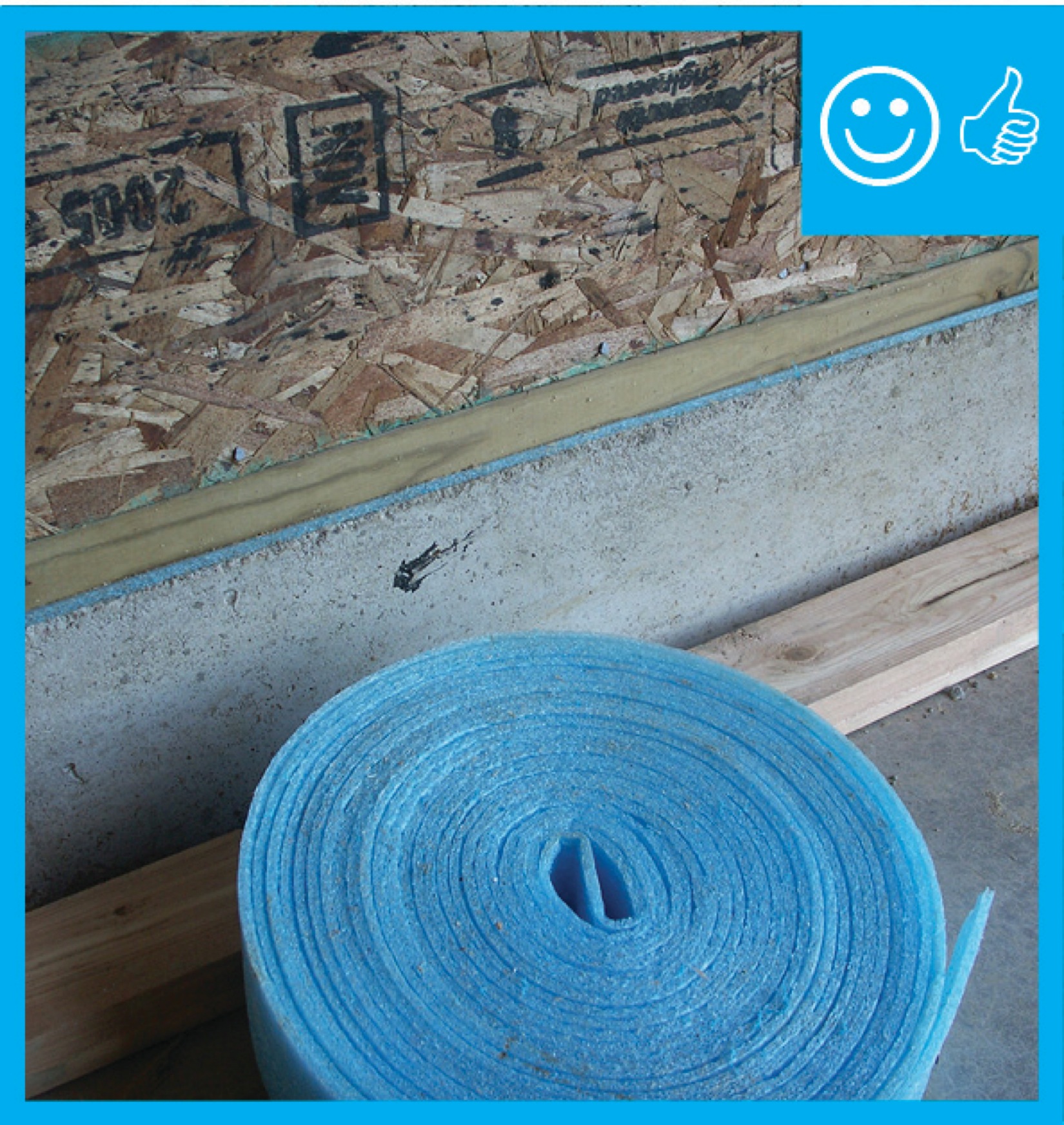
Right – The sill plate was sprayed with foam prior to installation atop foundation.
Image
Image
Image
Image
Right – This fire-rated wall assembly uses exterior gypsum board and an exterior siding of fiber-cement or metal to increase fire resistance.
Image
Image
Image
Image
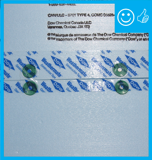
Right – Two-thirds of acrylic tape is offset above the joint and over and above the fasteners
Image
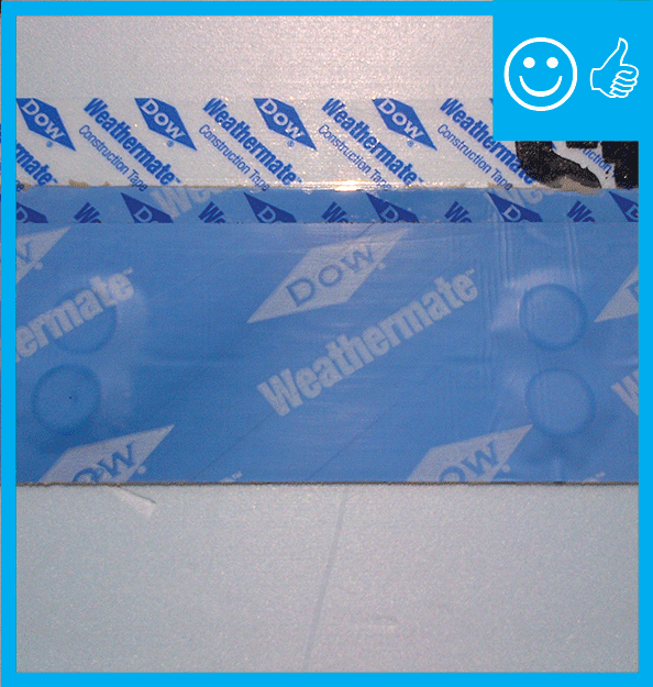
Right – two-thirds of the blue butyl flashing tape is above the sheathing seam; the top edge of the butyl flashing tape is covered with clear sheathing tape that is also offset so two-thirds is above the top edge of the butyl flashing.
Image
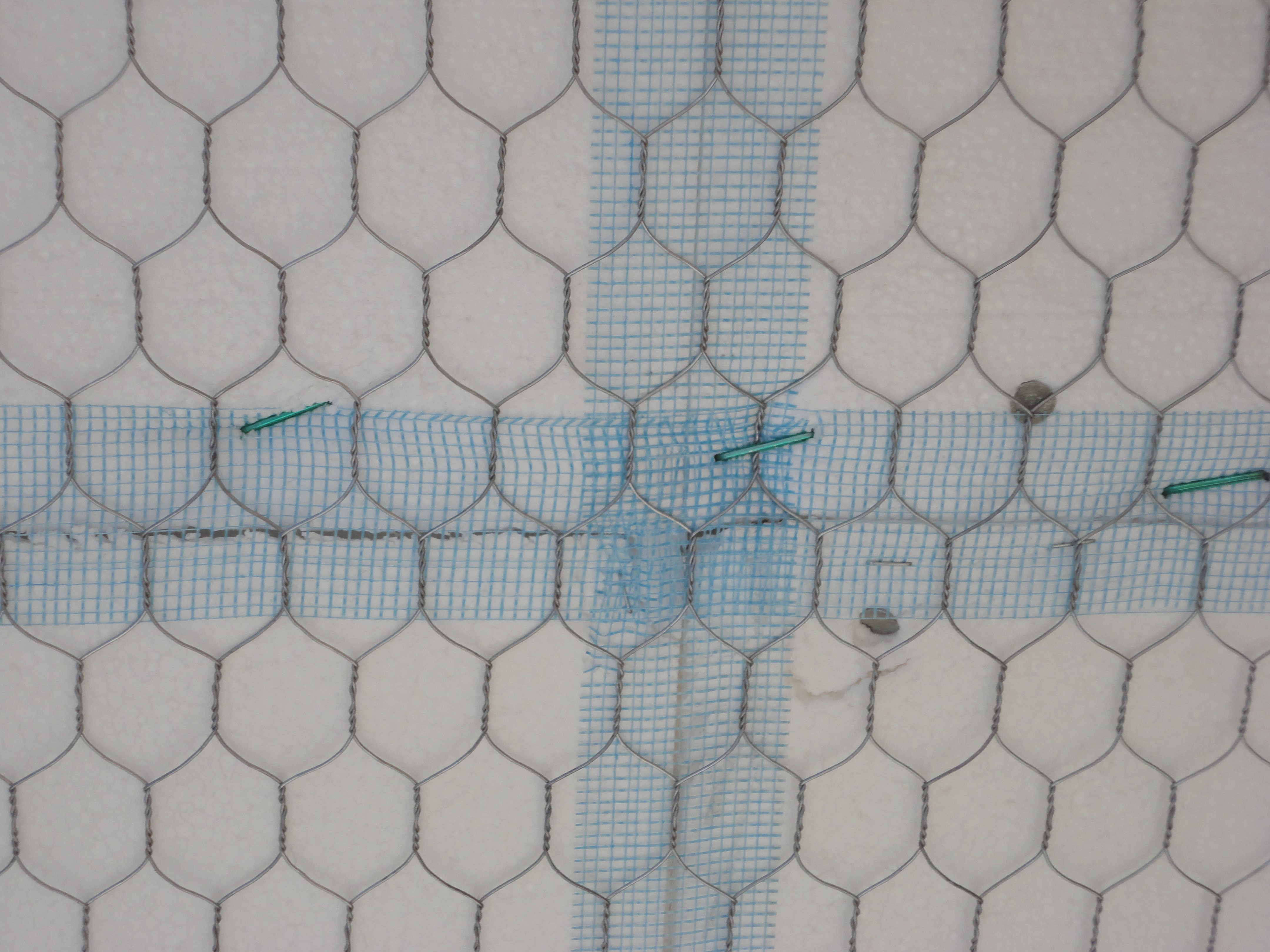
Right: All joints in the rigid foam are taped to keep stucco out of joints for even drying. Mesh tape (shown here) is used with expanded polystyrene (EPS); acrylic sheathing tape or self-adhered membrane is used with XPS
Image
Image
Image
Image
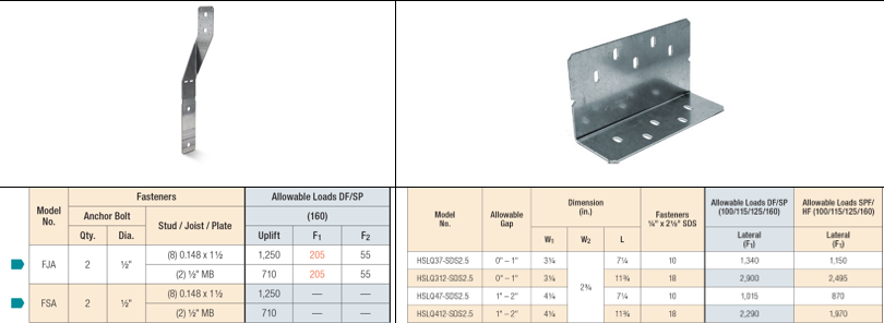
Shear Strength Comparison Between a Foundation Stud Anchor (on left) and a Shear Transfer Angle (on right)
Image
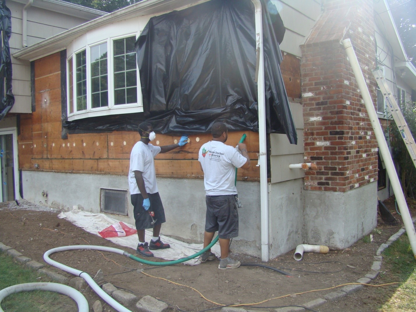
Siding has been removed so cellulose insulation can be dense-packed into the exterior walls of this home
Image

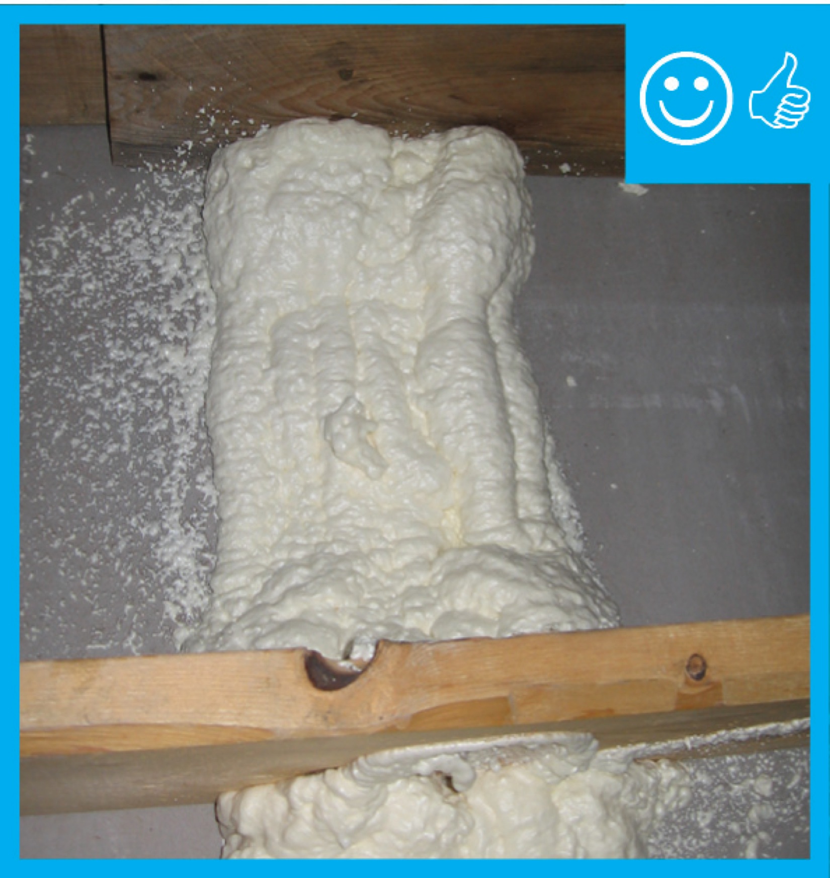
Spray foam adhesive provides an extra water resistant layer to the joints and seams on the inside of attics.
Image
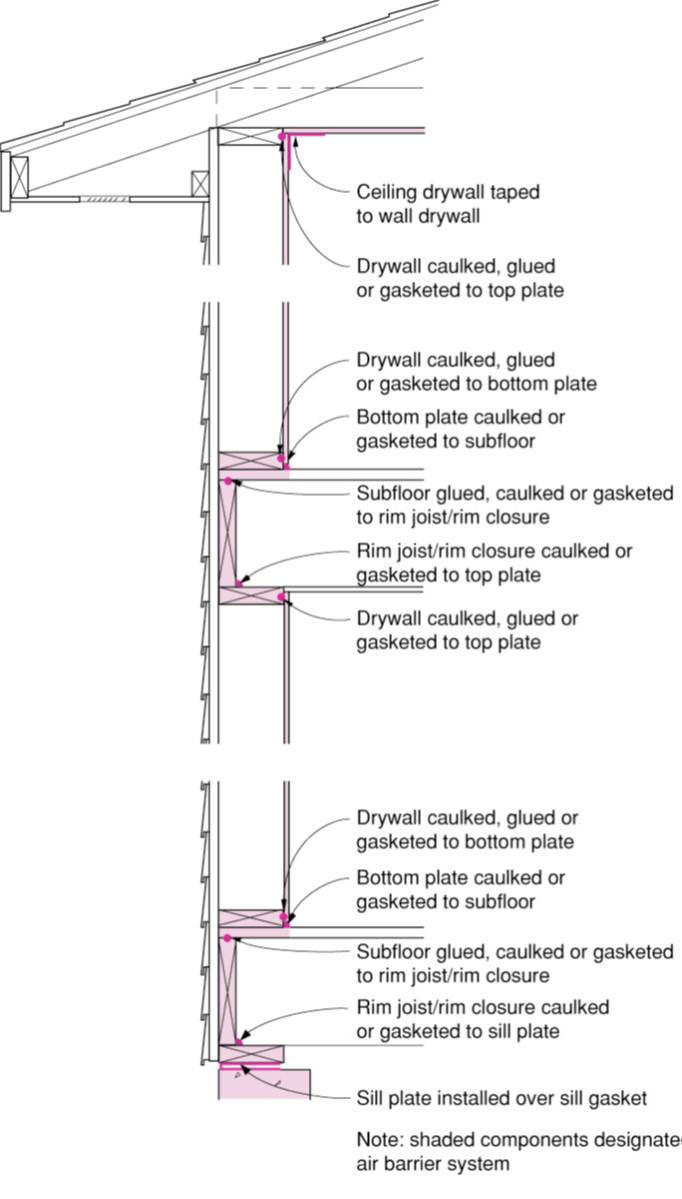
Spray foam provides a critical seal between the subfloor, rim joist, and sill plate
Image
Stucco is installed over rigid insulation, which is installed over a drainage plane consisting of a drainage gap and building wrap layer over the sheathing
Image
Image
Image
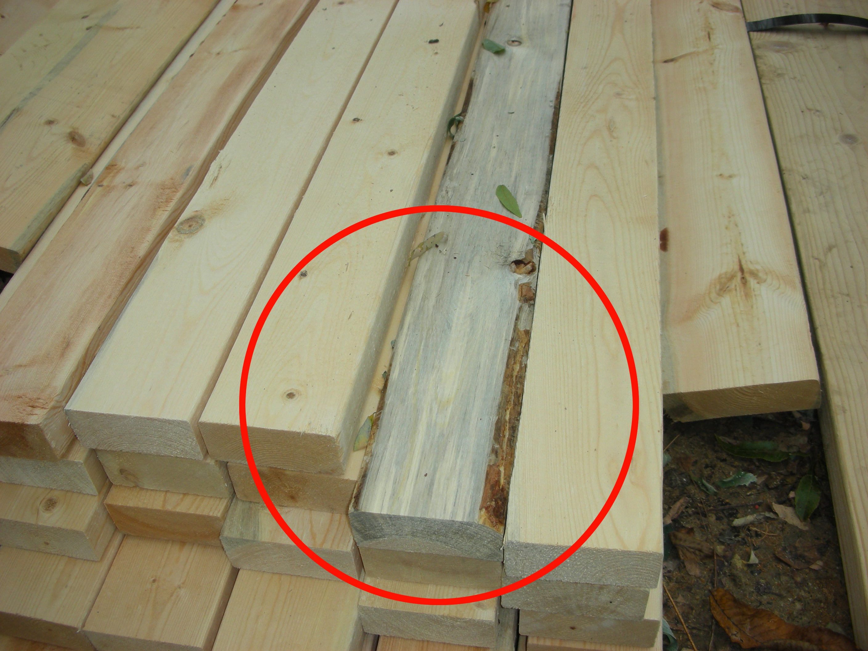
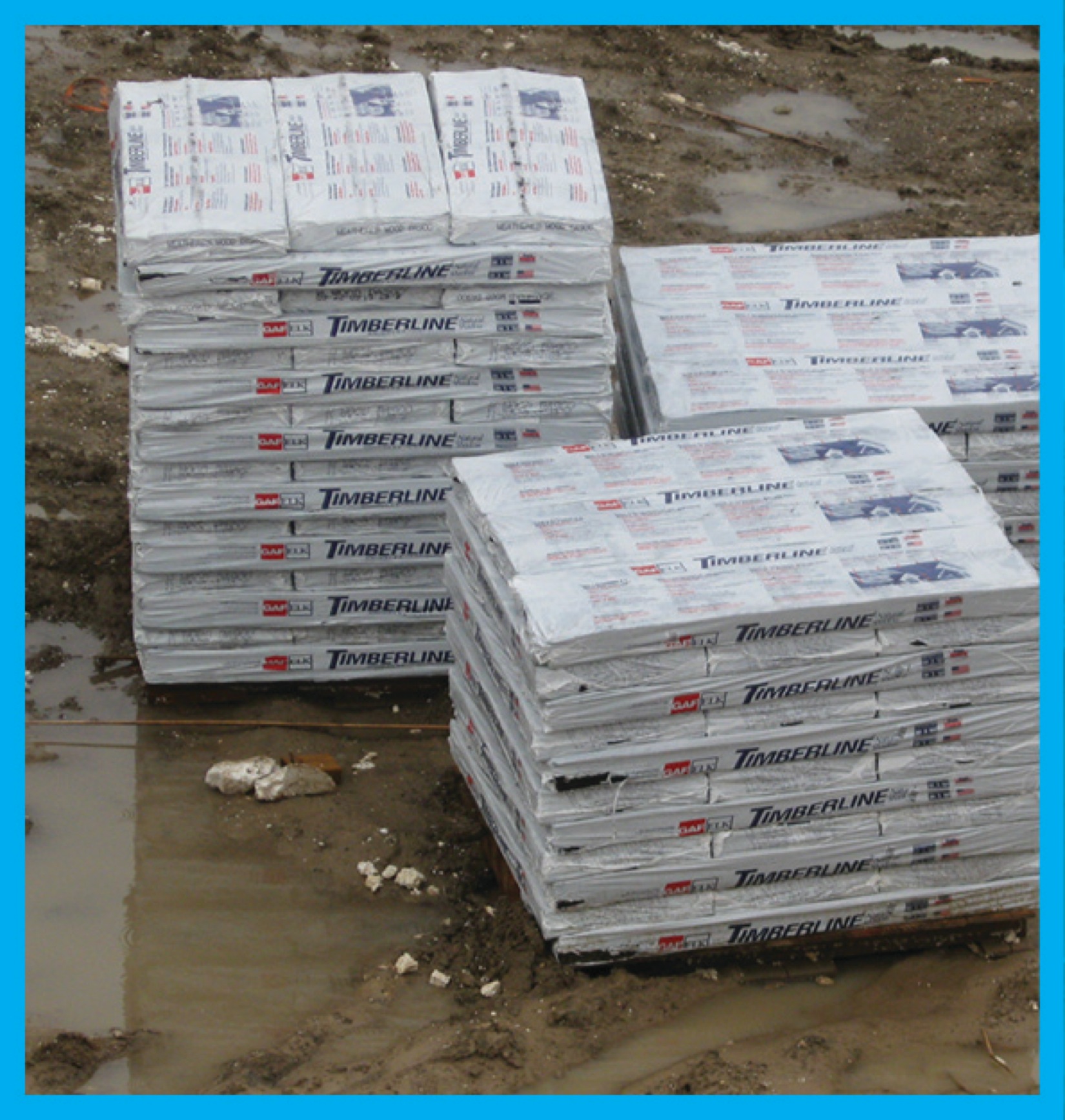
The board in the center of this photograph shows blue stain (not lumber mold), a discoloration of the wood caused by a fungus affecting the living tree, which did not harm the structural integrity of the wood.
Image
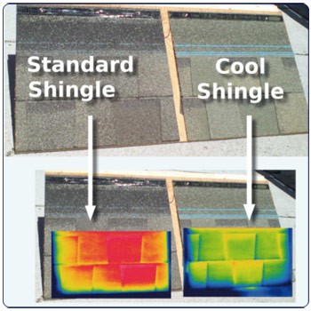
The cool shingles on the right have been coated with a ceramic coating to reflect near-infrared radiation, resulting in a cooler roof as shown by these thermal images (red and yellow are hotter, green and blue are cooler).
Image
The drain pans sit below the cooling coil to catch condensate and direct it to a drain line
Image
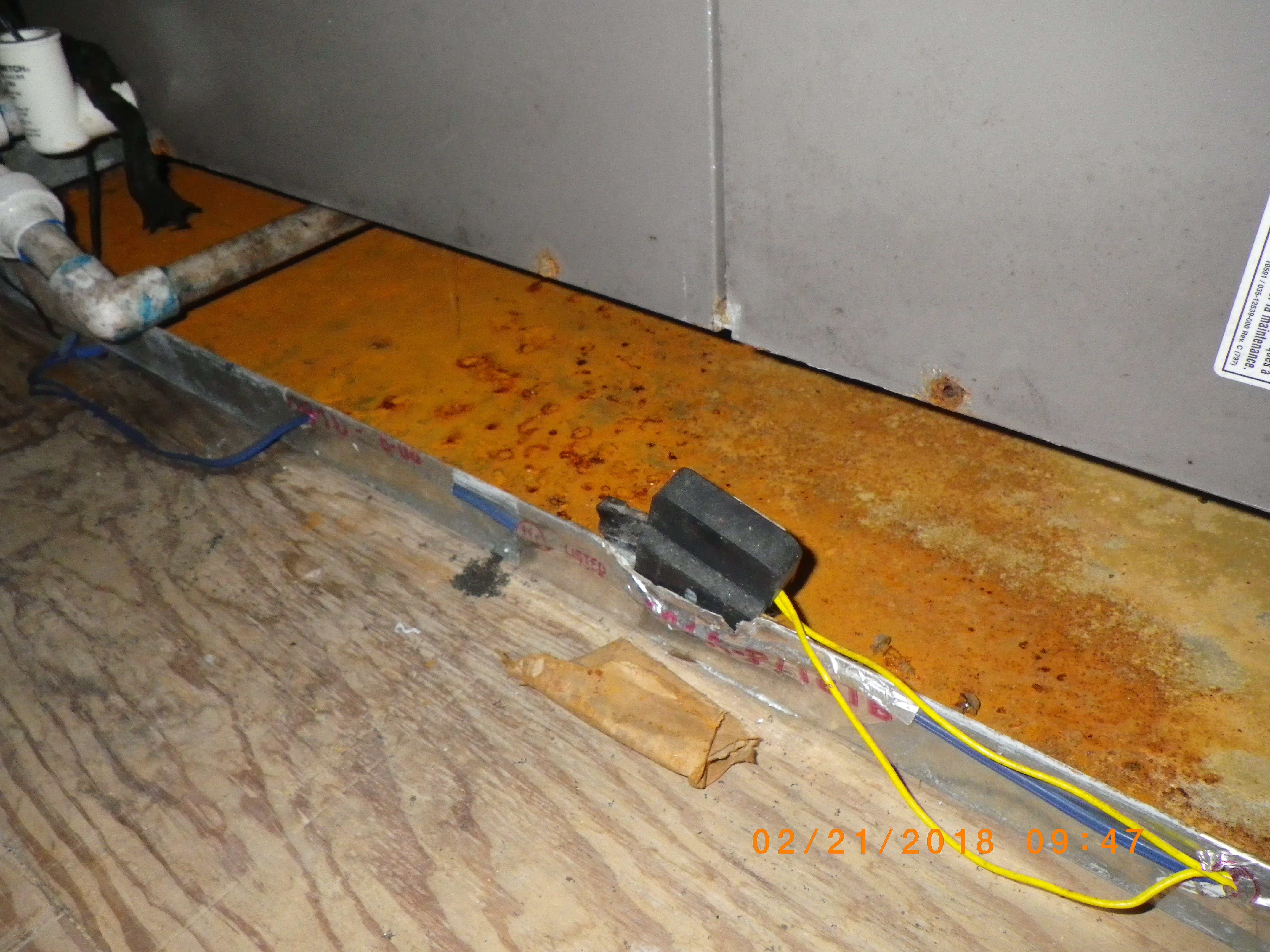
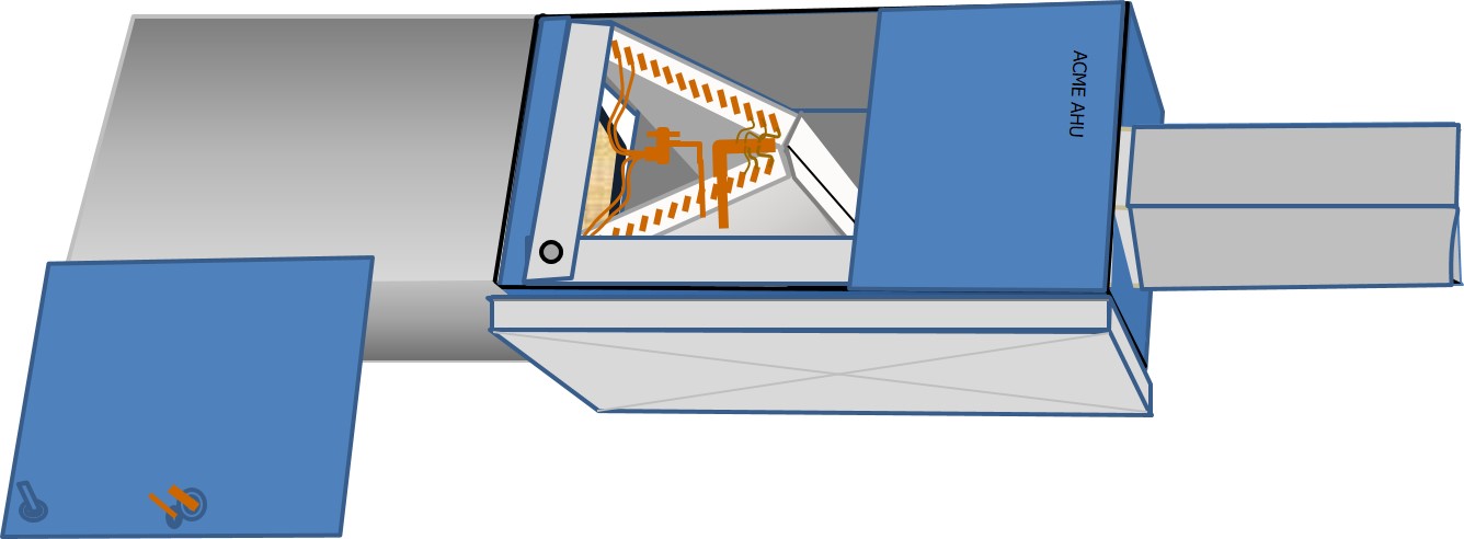
The HVAC equipment's condensate drain pan is equipped with a water-level detection device that will shut off the equipment if the water level pan in the pan gets too high
Image
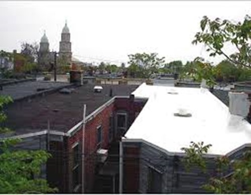
The white TPO membrane roof on the row house on the right performs extremely well at reflecting solar energy and maintaining cool surface temperatures while the black EPDM membrane roof on the left heats up rapidly in the sunlight
Image
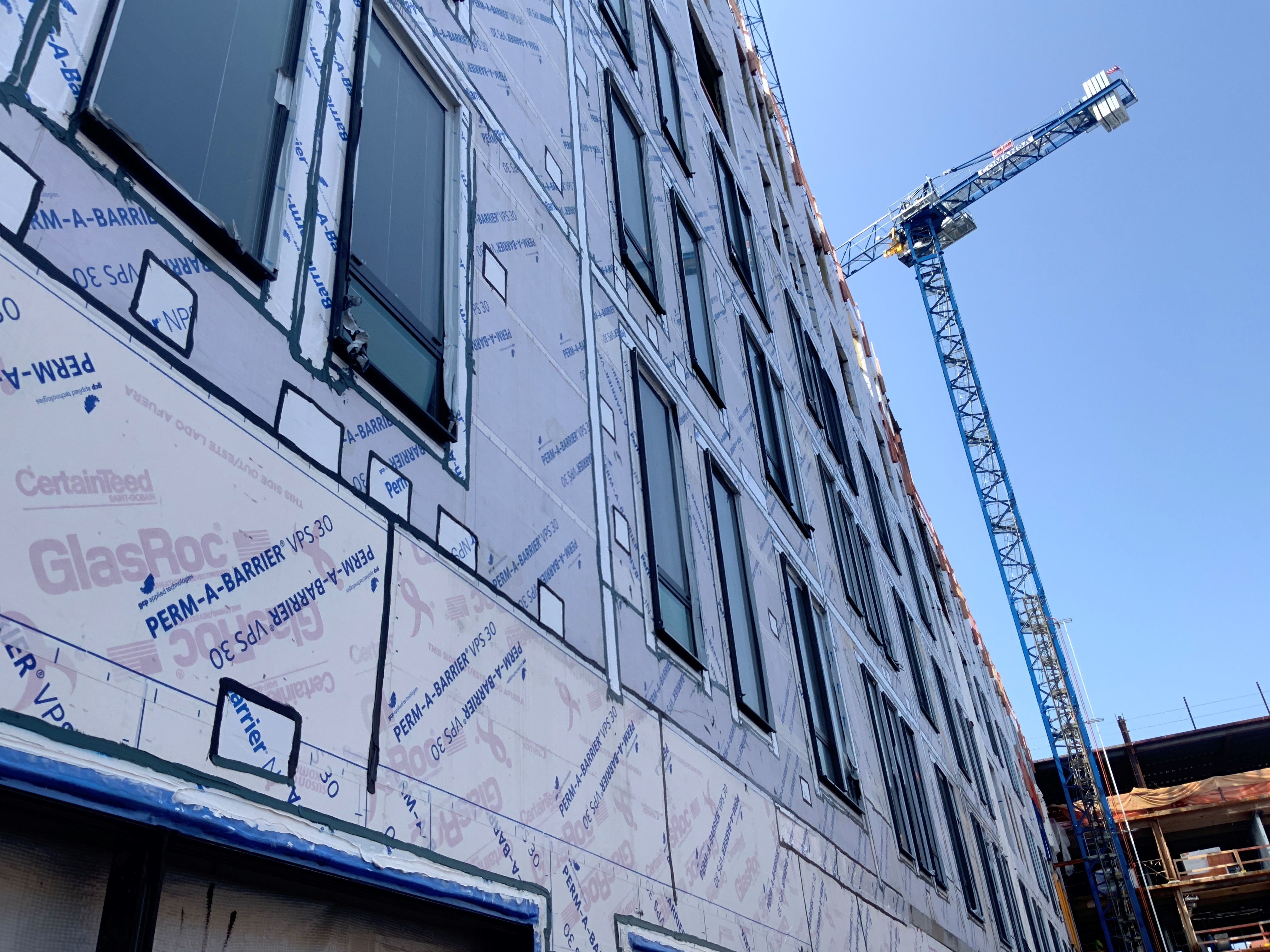
The windows in this building are connected to the fully adhered water and air control layer using fluid-applied flashing
Image
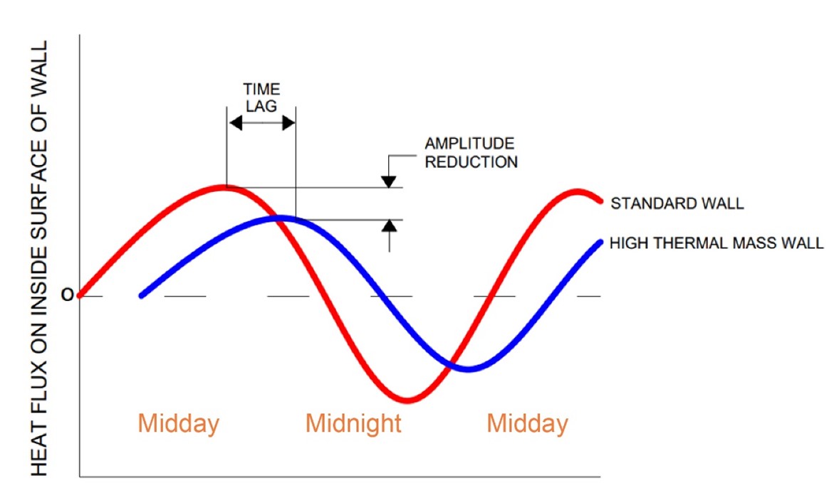
Thermal mass causes a time lag in the transfer of heat as well as a dampening of peak temperatures, as shown by this plot
Image

These wildfire-resistant decks have a solid decking surface, metal railings, and the underside timber supports are covered with flame-resistant fiber cement board; also the decking is set back from the vegetated slope.
Image
Image
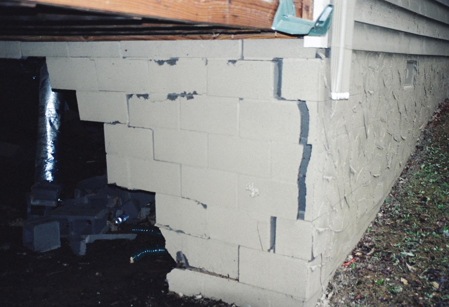
This concrete block foundation cracked due to lack of steel rebar reinforcement.
Image
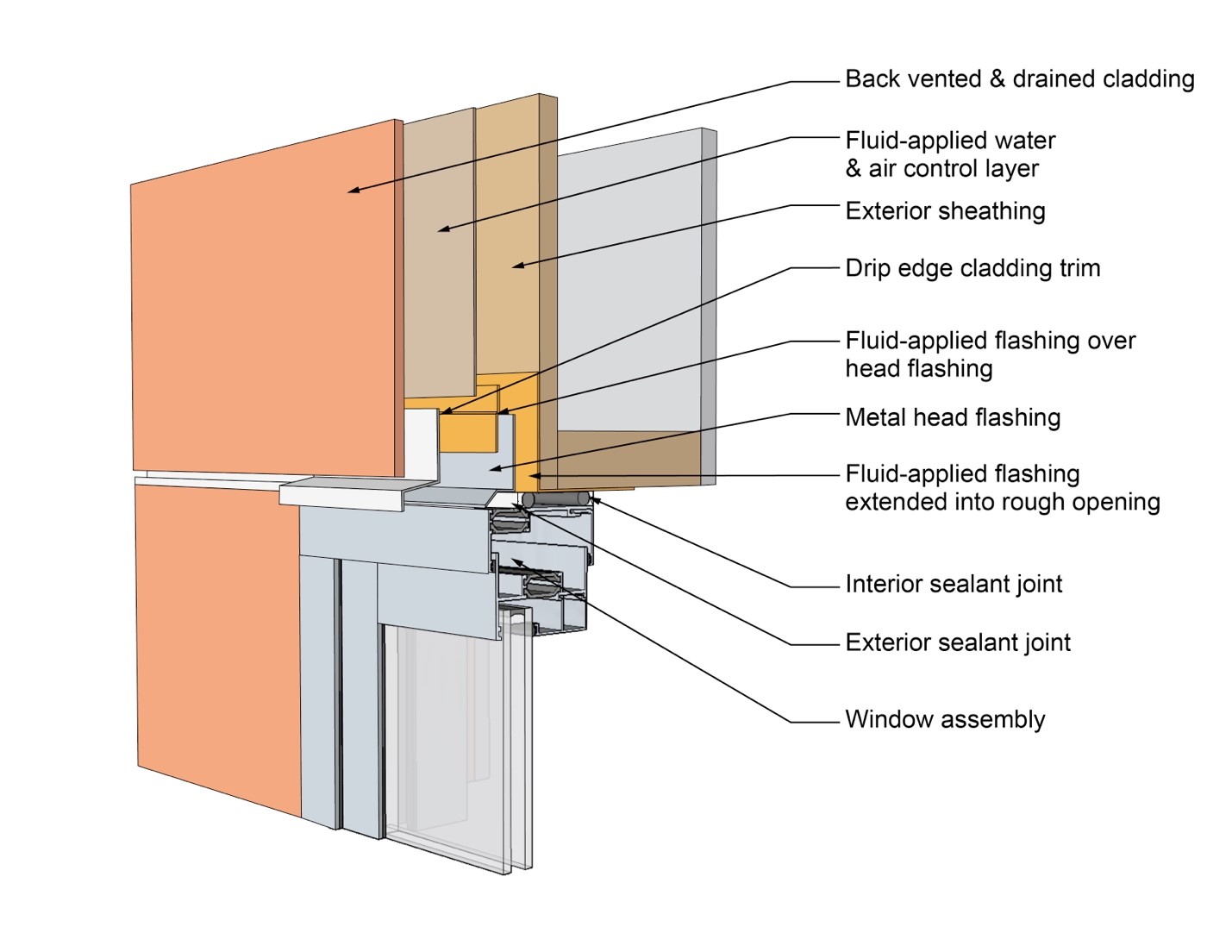
This drawing shows key head details for a window installation using a fluid-applied flashing on a wall with a fluid-applied water and air control layer
Image
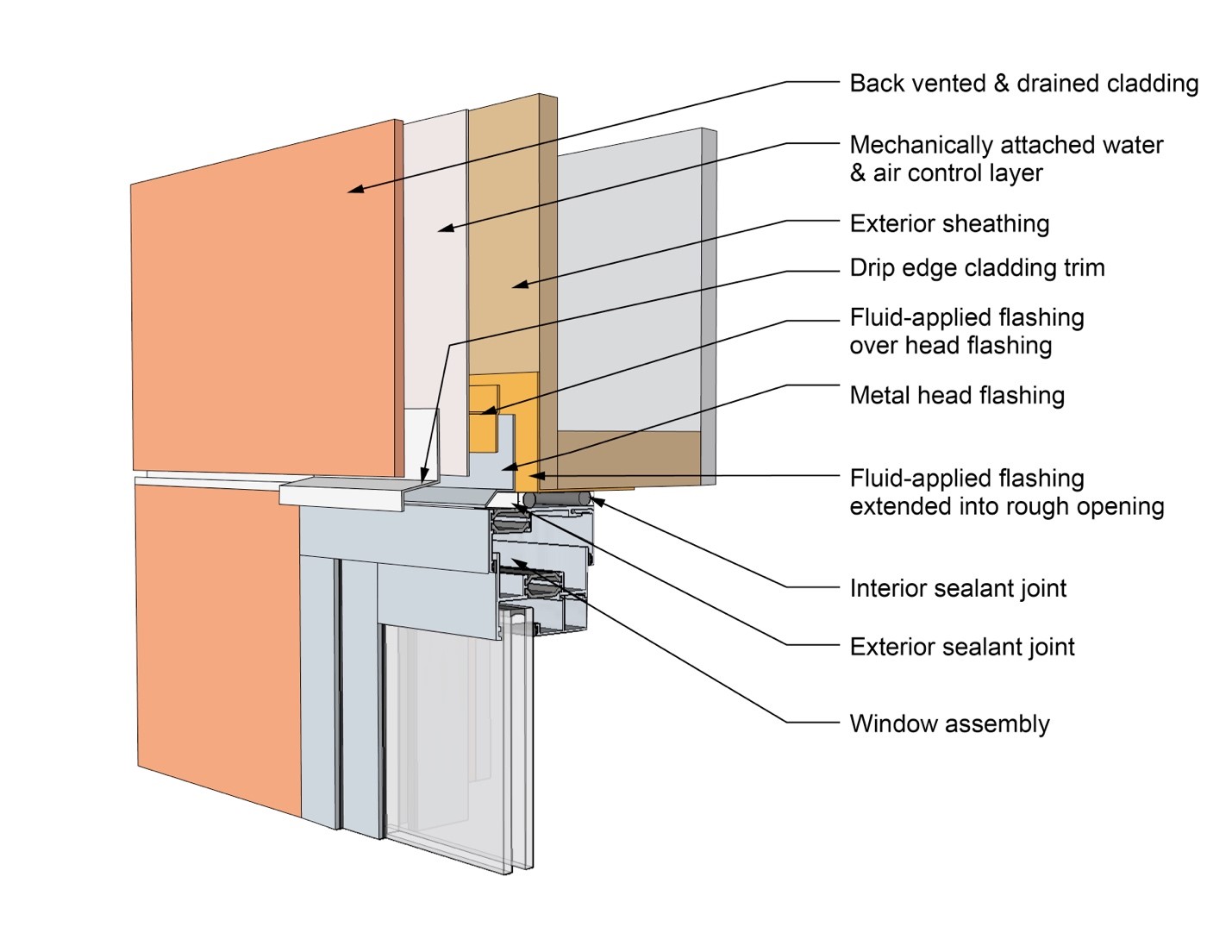
This drawing shows key head details for a window installation using a fluid-applied flashing on a wall with a mechanically attached water and air control layer
Image
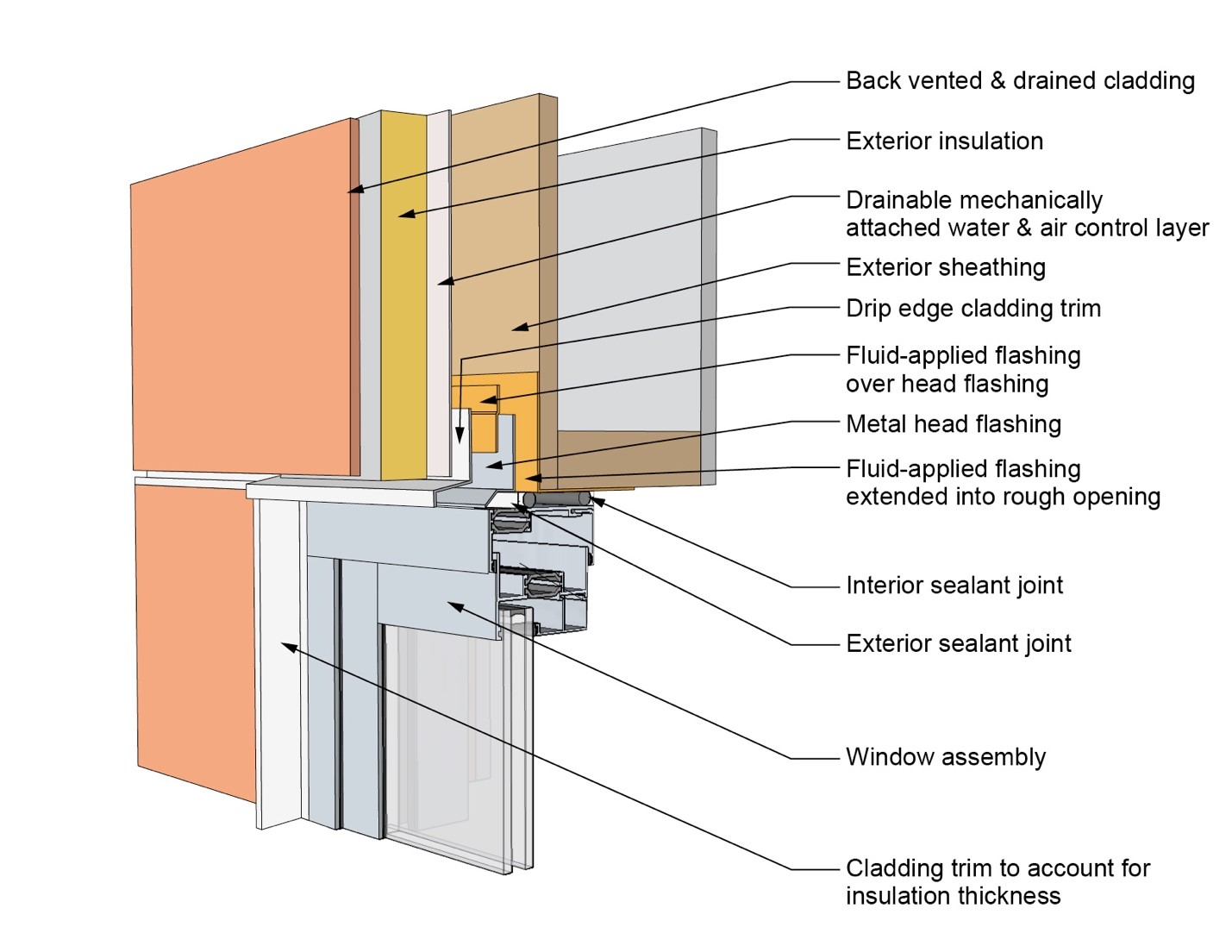
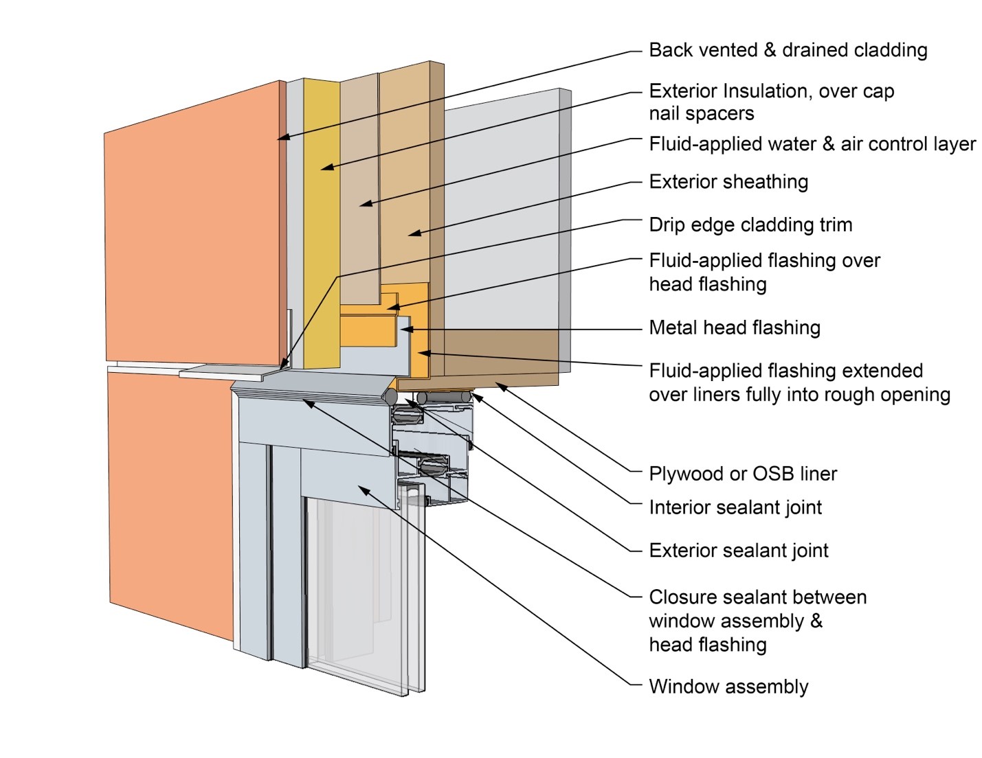
This drawing shows key head details for a window installation using a fluid-applied flashing on a wall with a mechanically attached water and air control layer and continuous insulation
Image
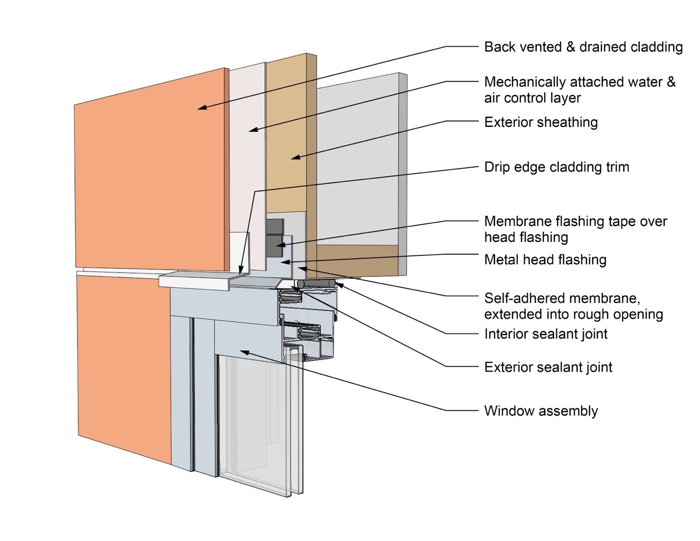
This drawing shows key head details for a window installation using a self-adhered membrane tape flashing on a wall with a mechanically attached water and air control layer
Image
This drawing shows key head details for an “outie” window installation using a fluid-applied flashing on a wall with a fluid-applied water and air control layer and continuous insulation
Image
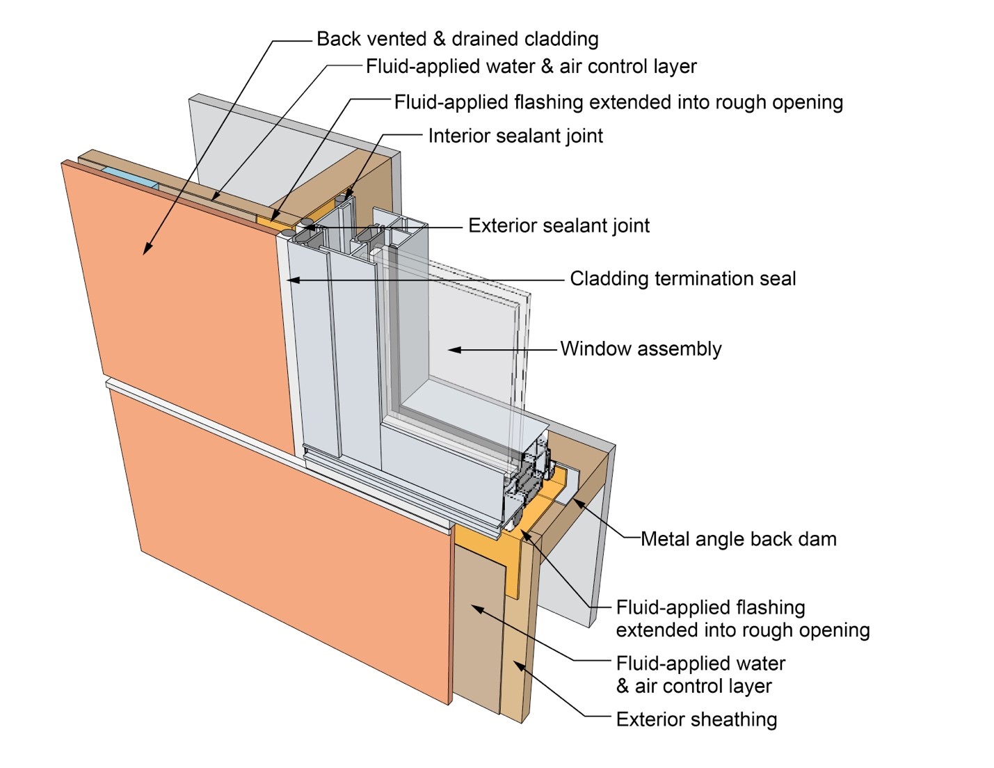
This drawing shows key jamb details for a window installation using a fluid-applied flashing on a wall with a fluid-applied water and air control layer
Image
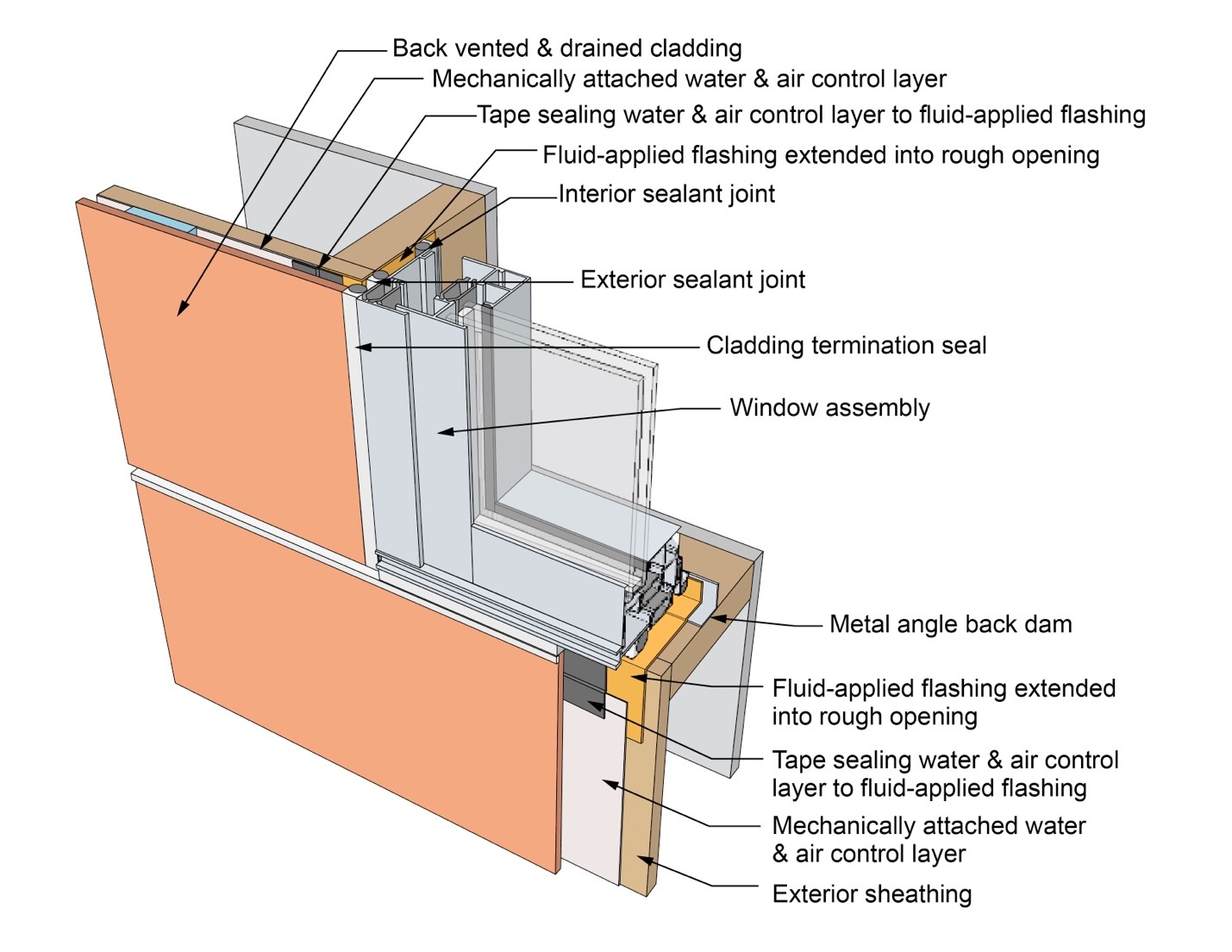
This drawing shows key jamb details for a window installation using a fluid-applied flashing on a wall with a mechanically attached water and air control layer
Image
This drawing shows key jamb details for a window installation using a fluid-applied flashing on a wall with a mechanically attached water and air control layer and continuous insulation
Image
This drawing shows key jamb details for a window installation using a self-adhered membrane tape flashing on a wall with a mechanically attached water and air control layer
Image
This drawing shows key jamb details for an “outie” window installation using a fluid-applied flashing on a wall with a fluid-applied water and air control layer and continuous insulation
Image
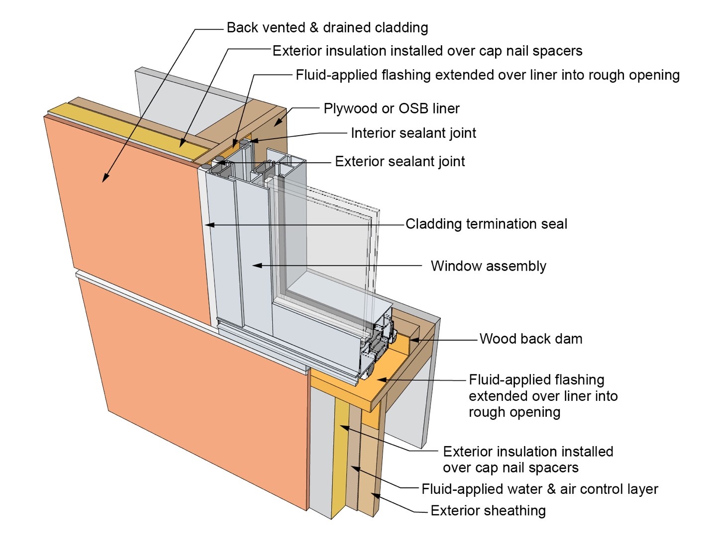
This drawing shows key sill details for a window installation using a fluid-applied flashing on a wall with a fluid-applied water and air control layer
Image
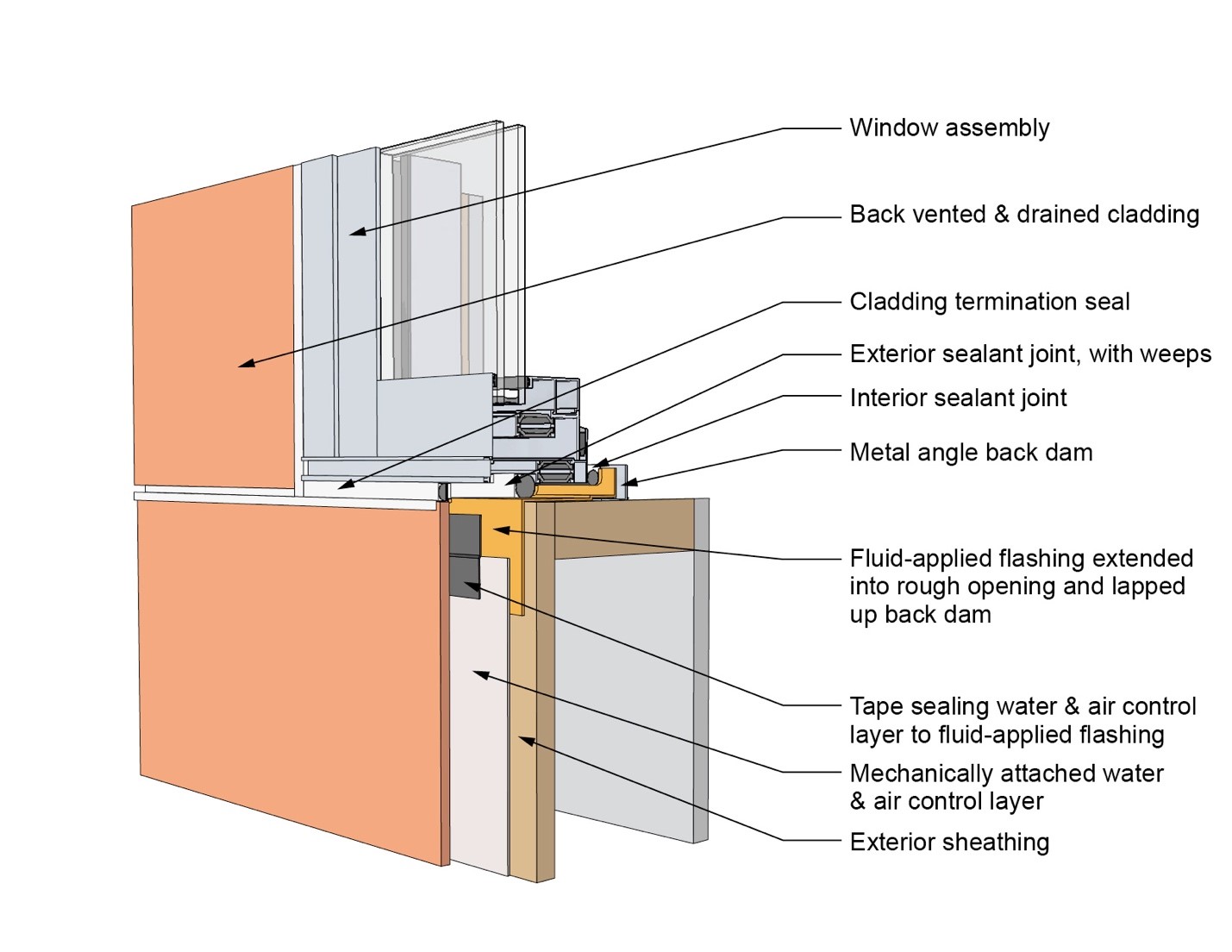
This drawing shows key sill details for a window installation using a fluid-applied flashing on a wall with a mechanically attached water and air control layer
Image
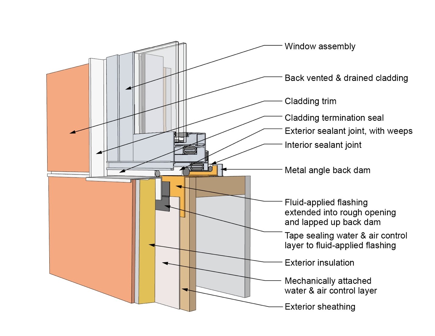
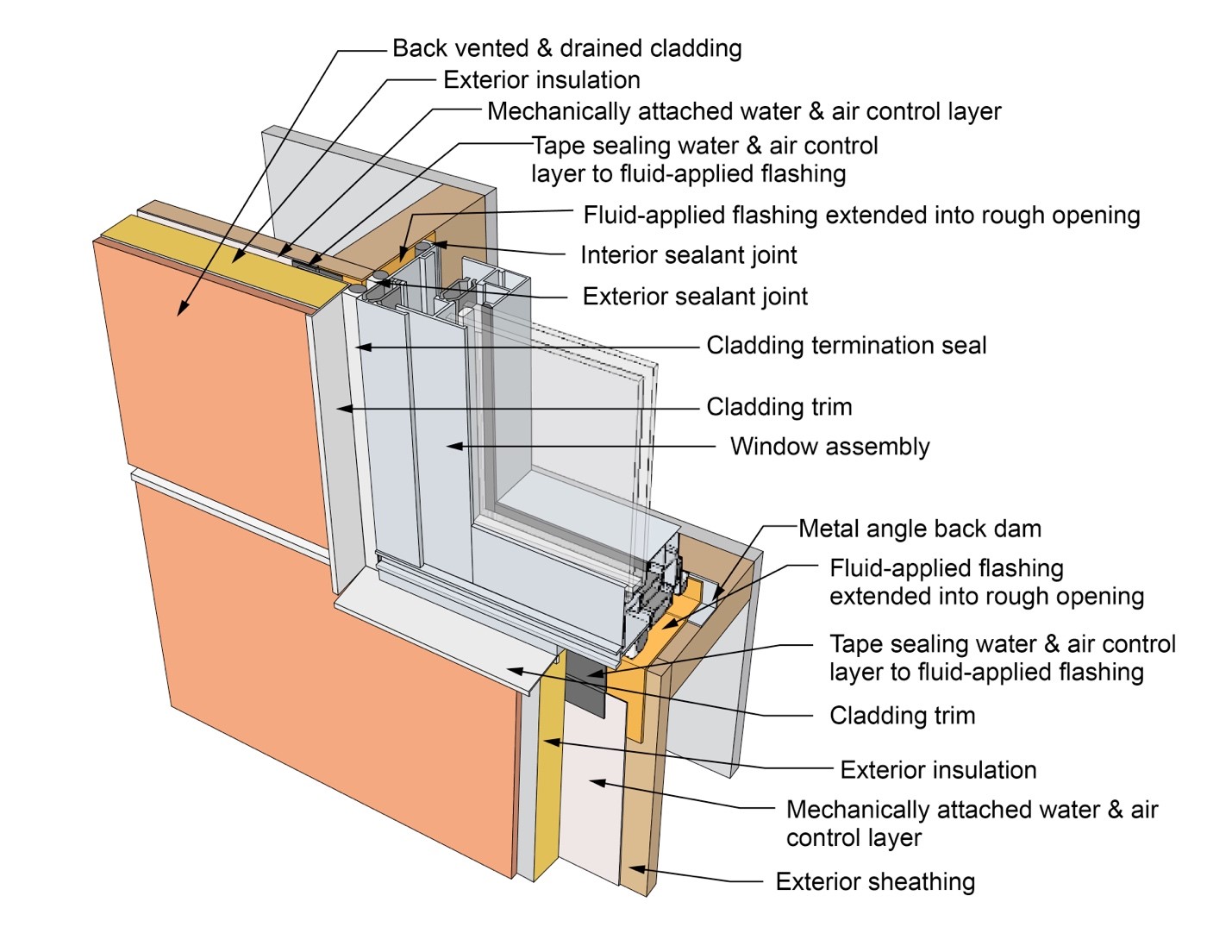
This drawing shows key sill details for a window installation using a fluid-applied flashing on a wall with a mechanically attached water and air control layer and continuous insulation
Image
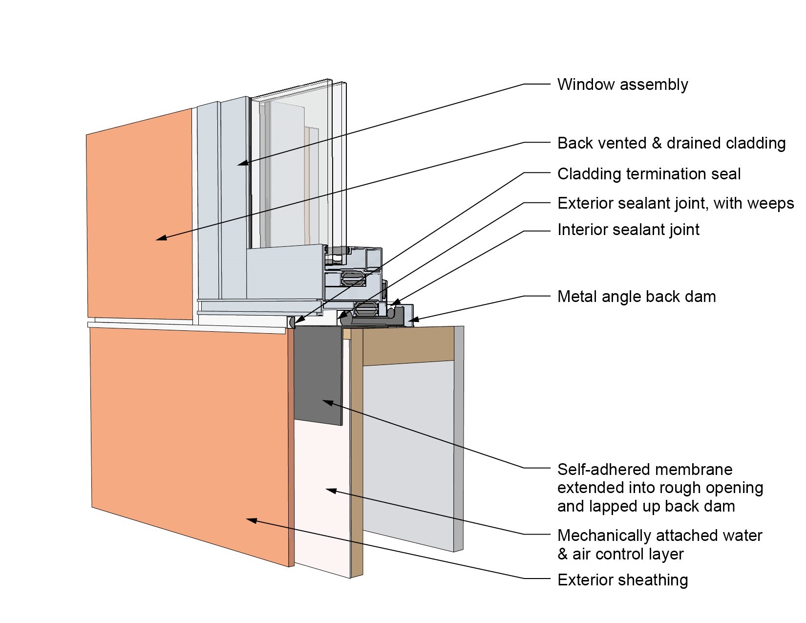
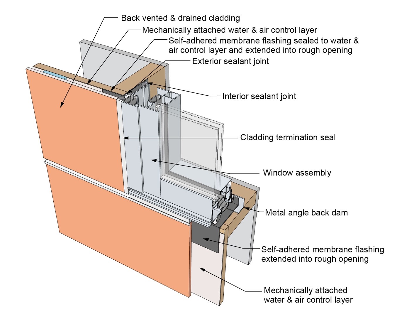
This drawing shows key sill details for a window installation using a self-adhered membrane tape flashing on a wall with a mechanically attached water and air control layer
Image
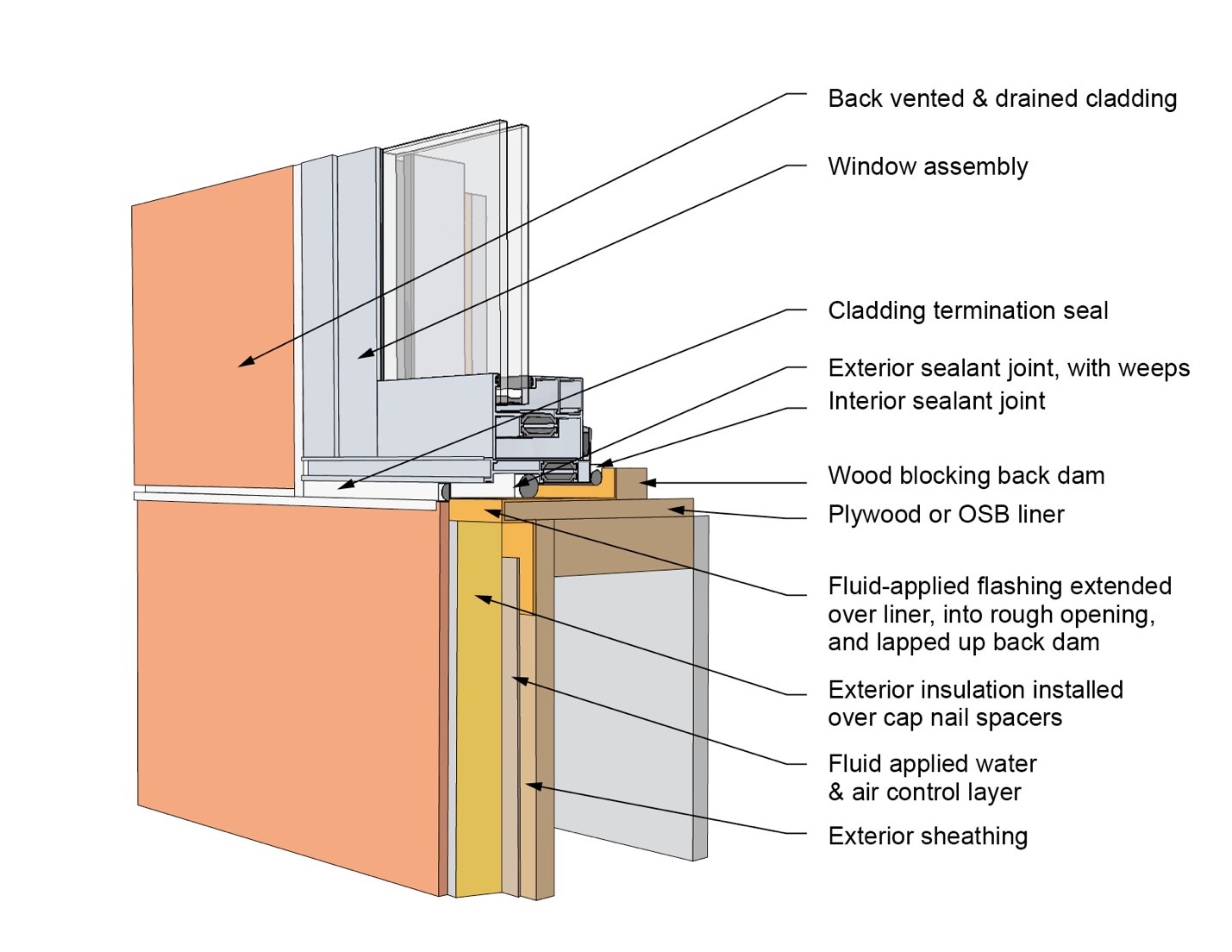
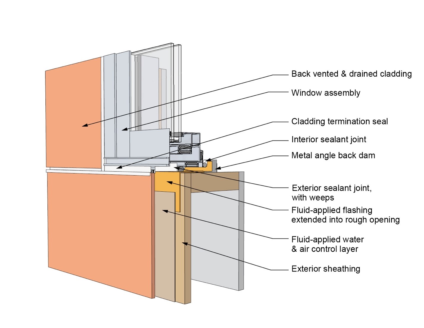
This drawing shows key sill details for an “outie” window installation using a fluid-applied flashing on a wall with a fluid-applied water and air control layer and continuous insulation