Showing results 51 - 100 of 198
Image
Image
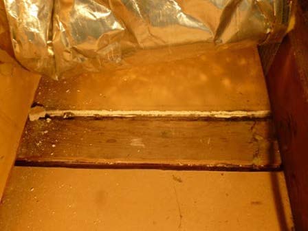
Gaps at shared common walls can be a significant source of air leakage in multi-family buildings
Image
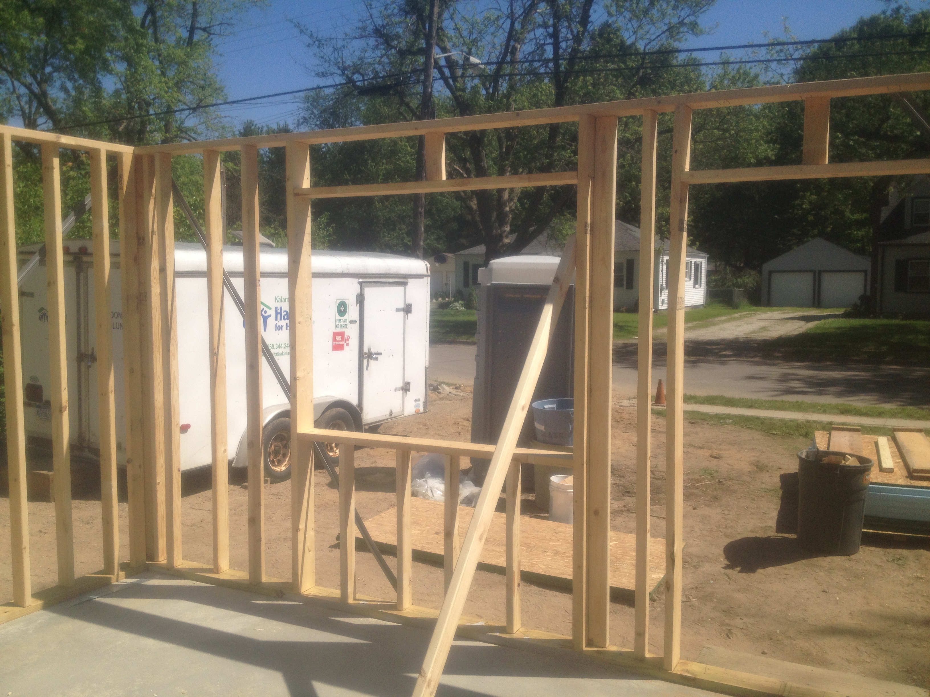
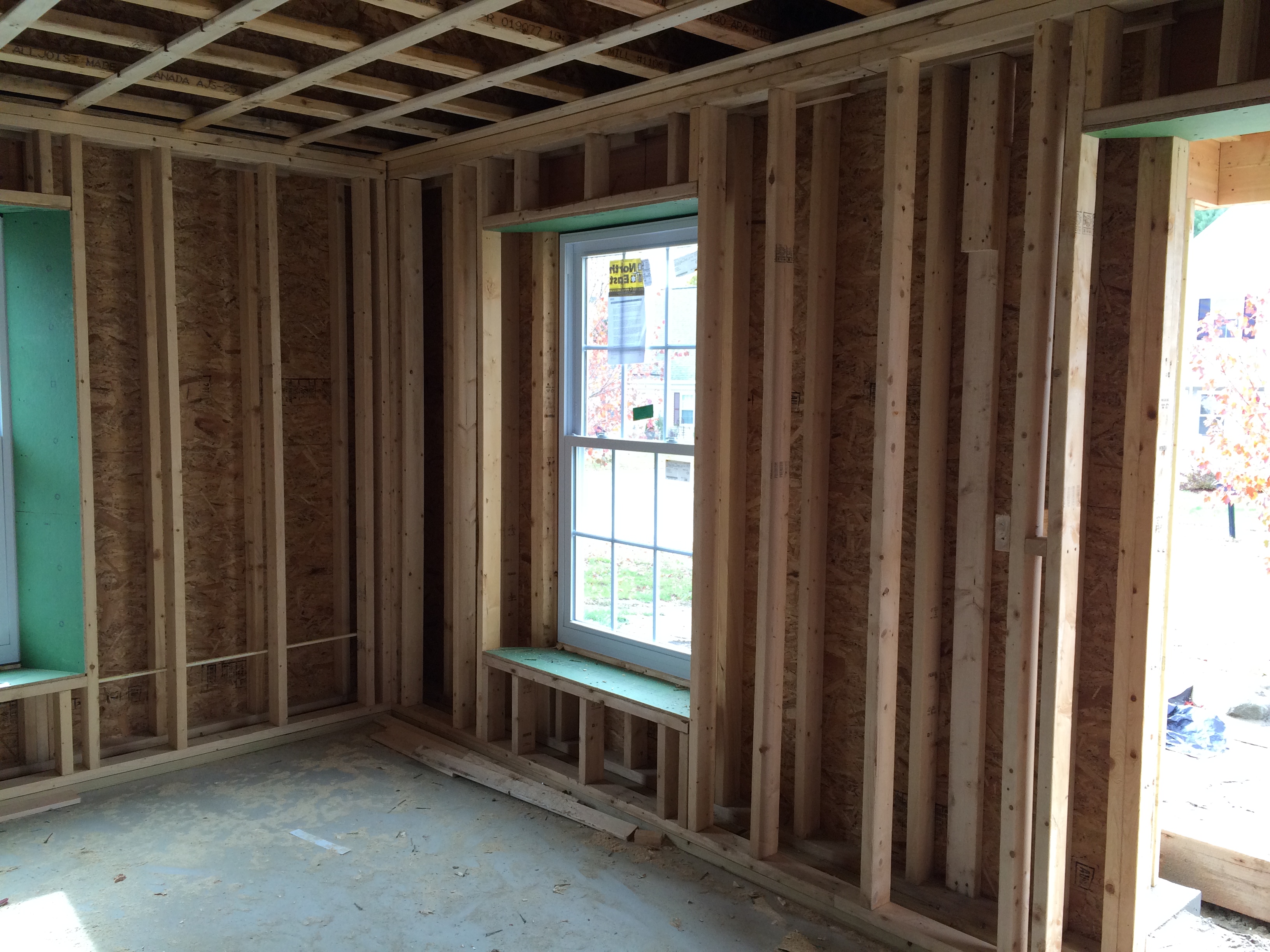
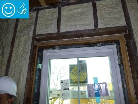
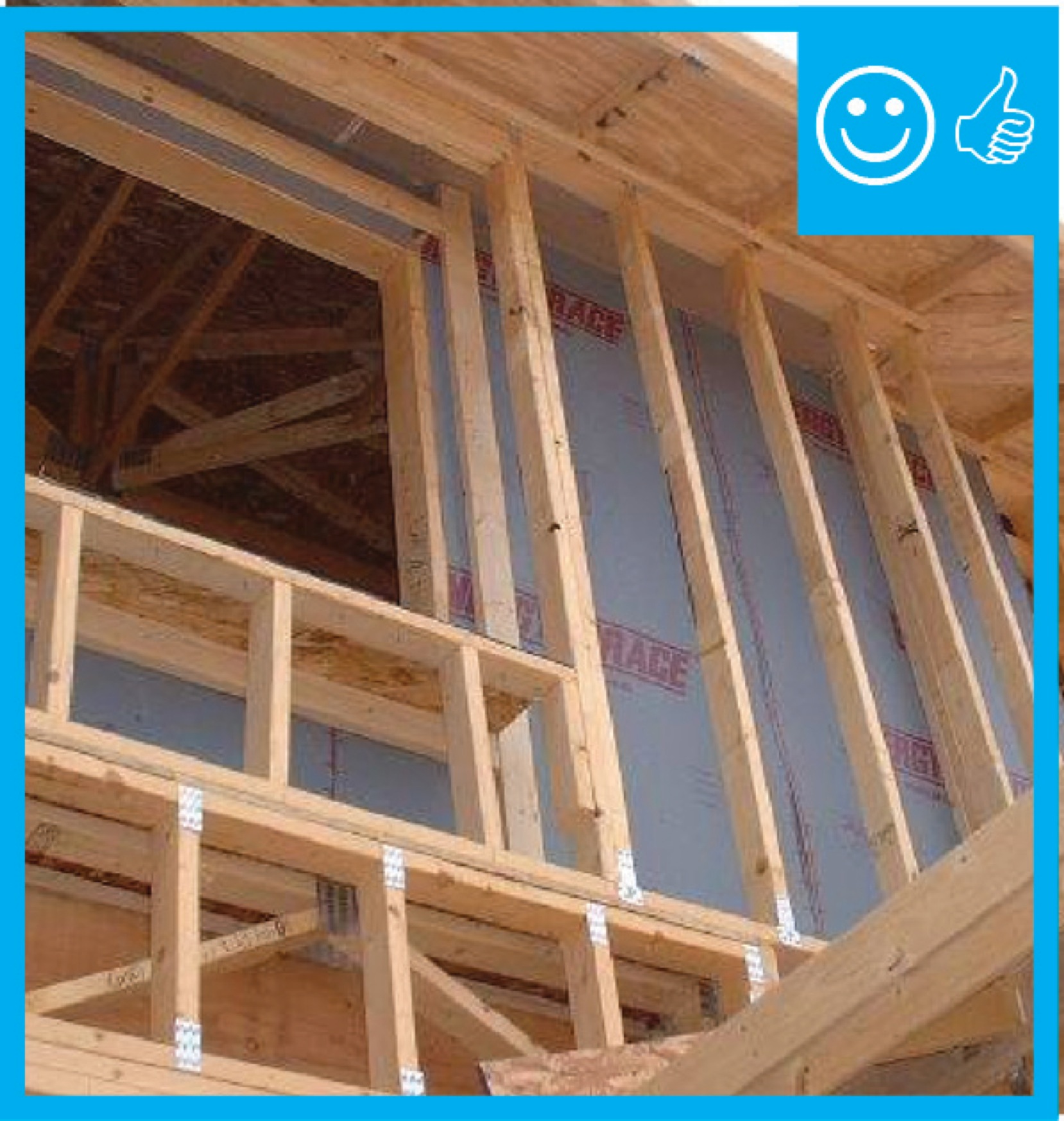
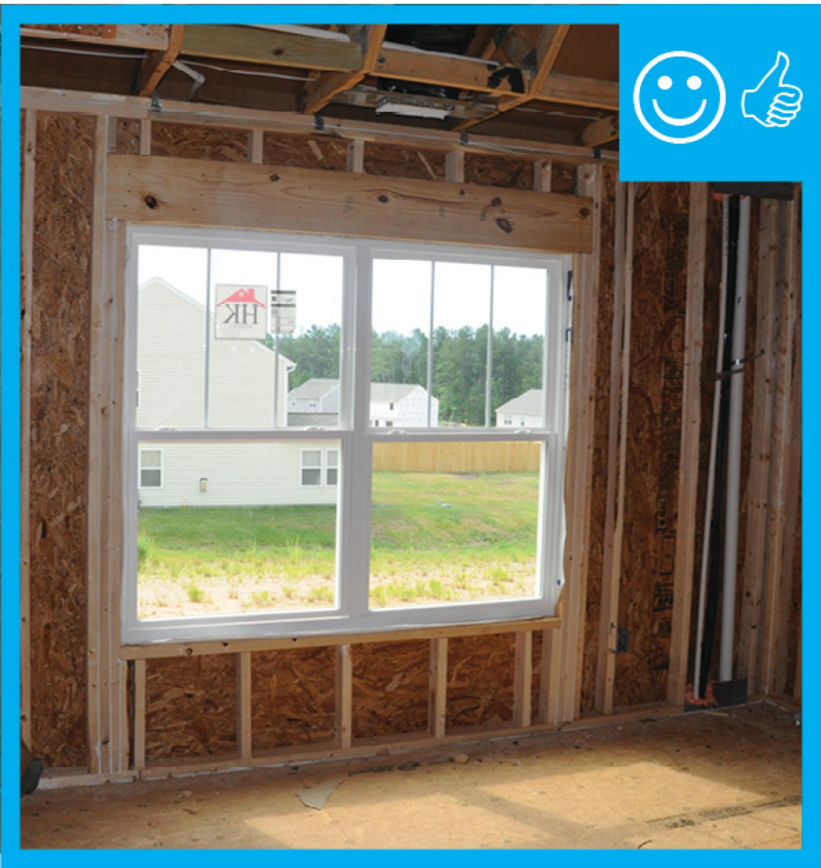
Headers over windows on non-load-bearing walls are open to allow room for insulation.
Image
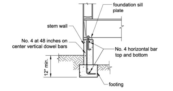
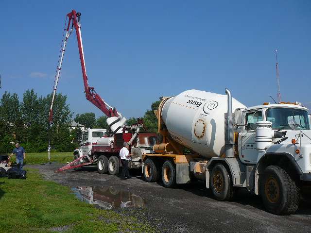
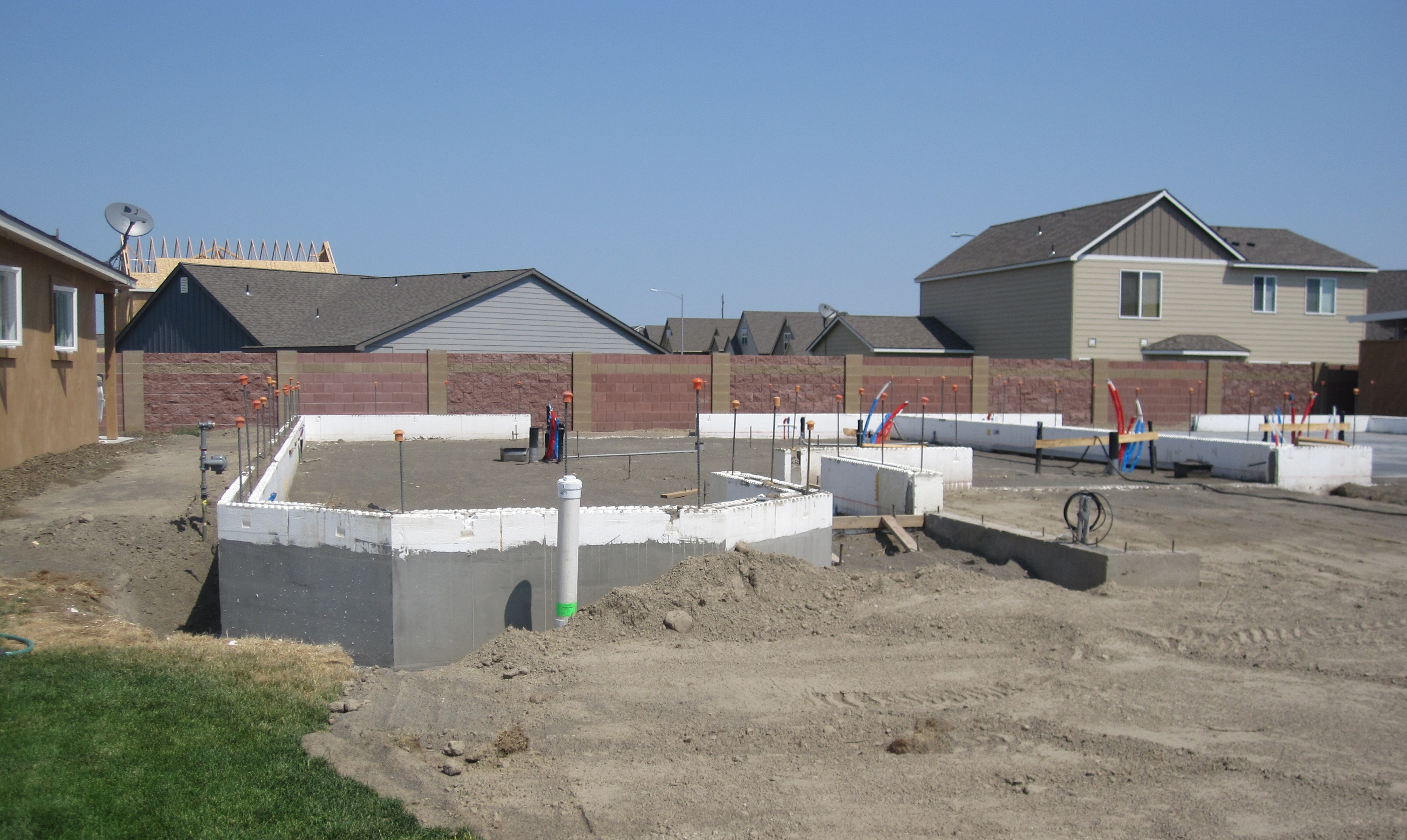
How to properly anchor a new home to its foundation with foundation sill plate, stem wall, and footing
Image
Image
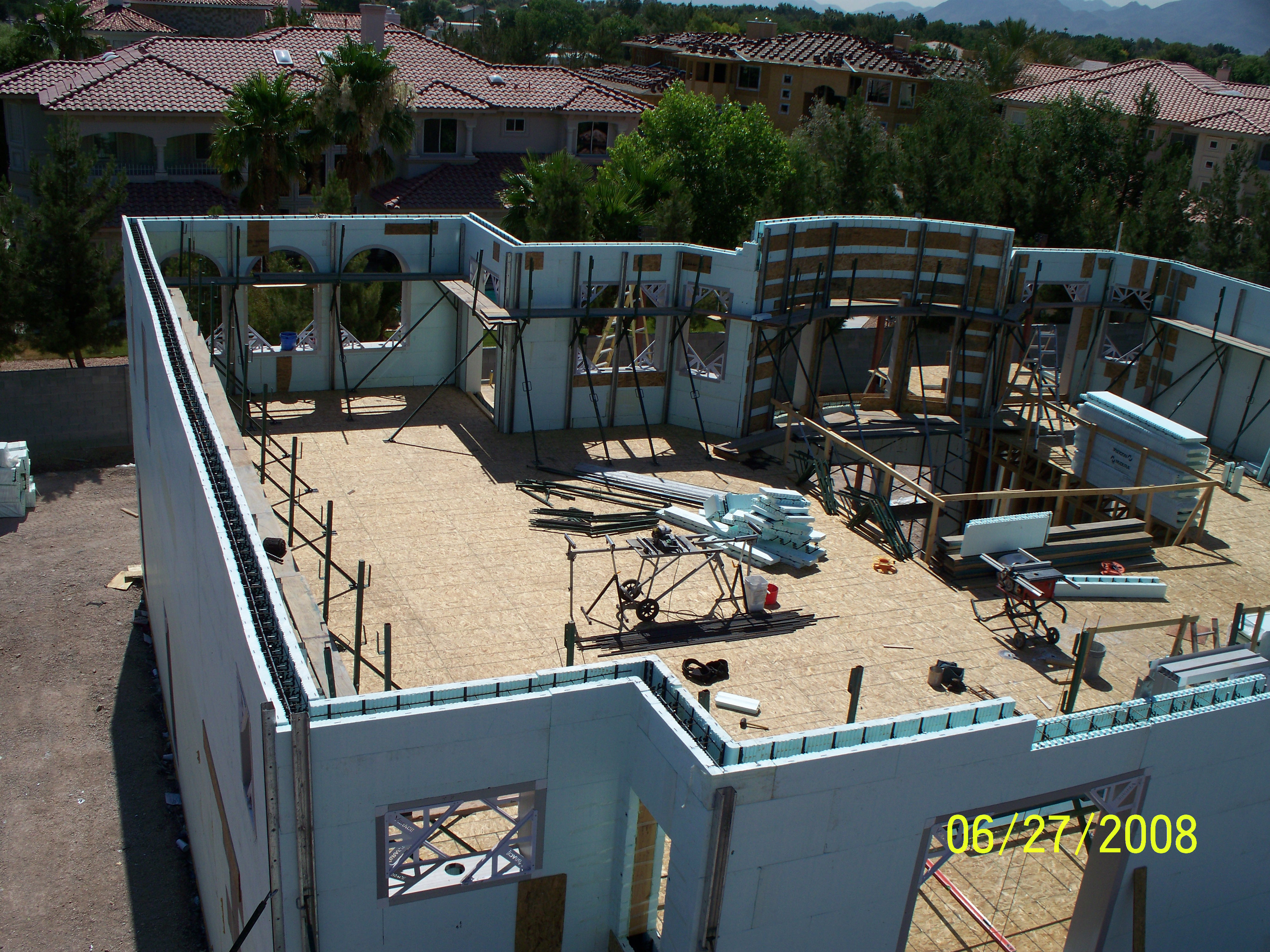
ICFs provide continuous wall insulation from the roof to the footing with very little thermal bridging
Image
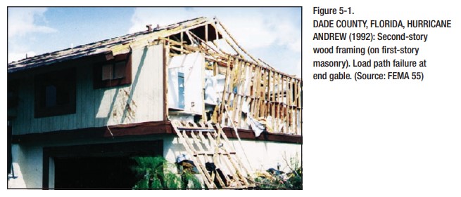
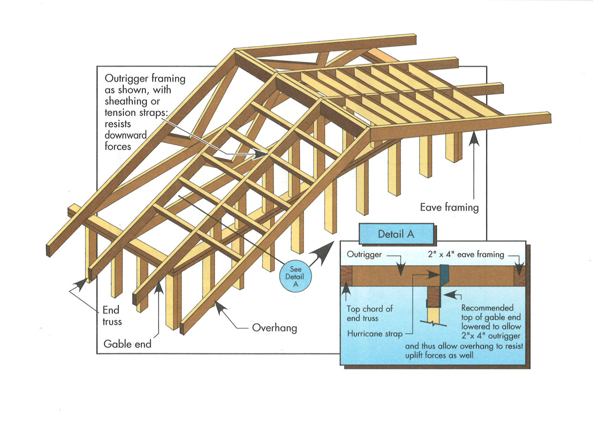
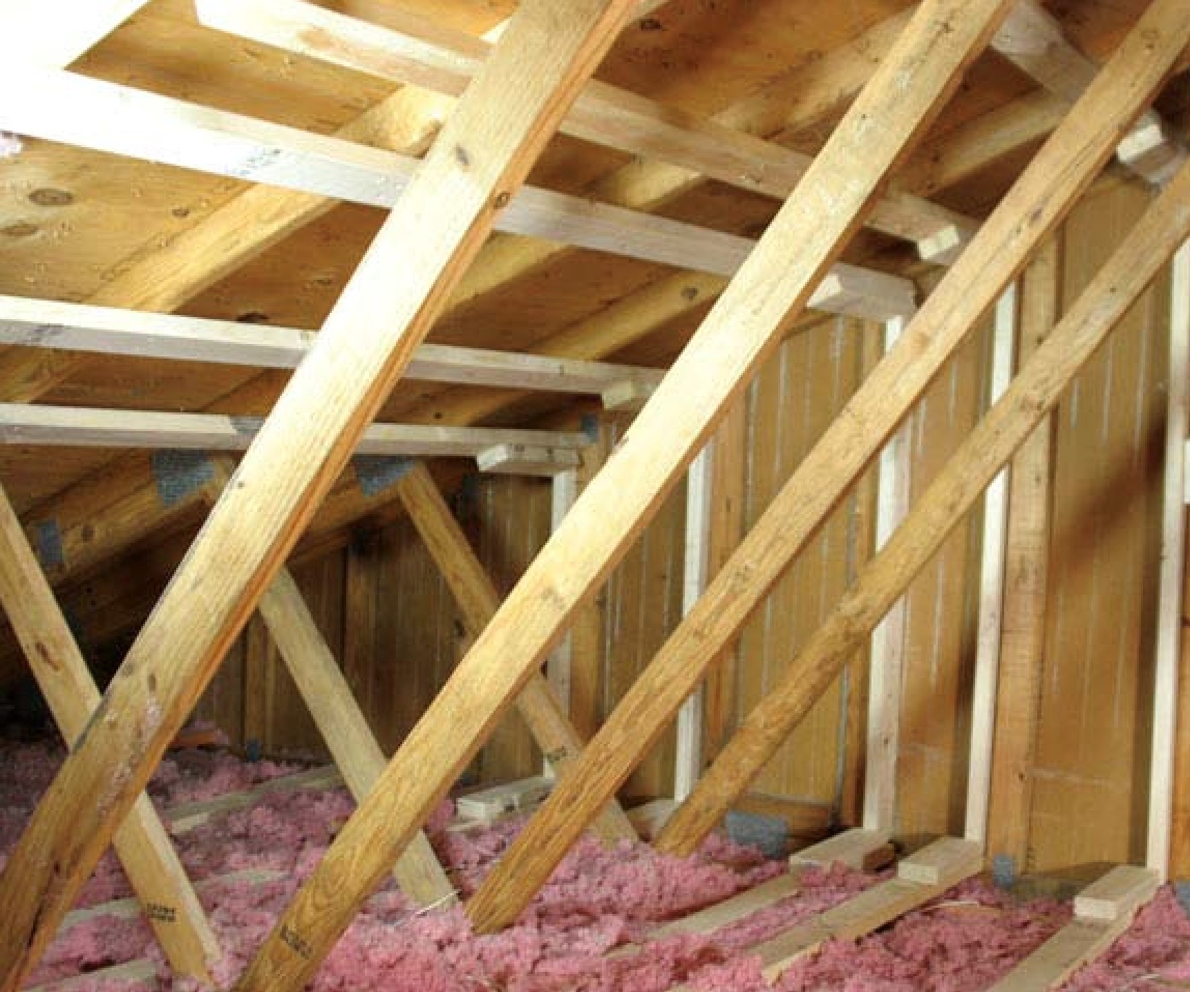
Improper continuous load path design lacking bracing results in the failure of gable end walls under high wind conditions.
Image
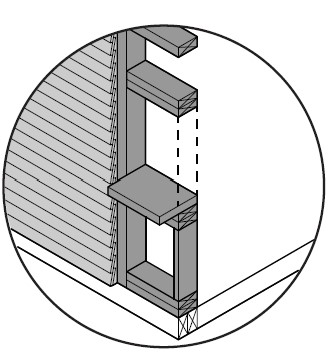
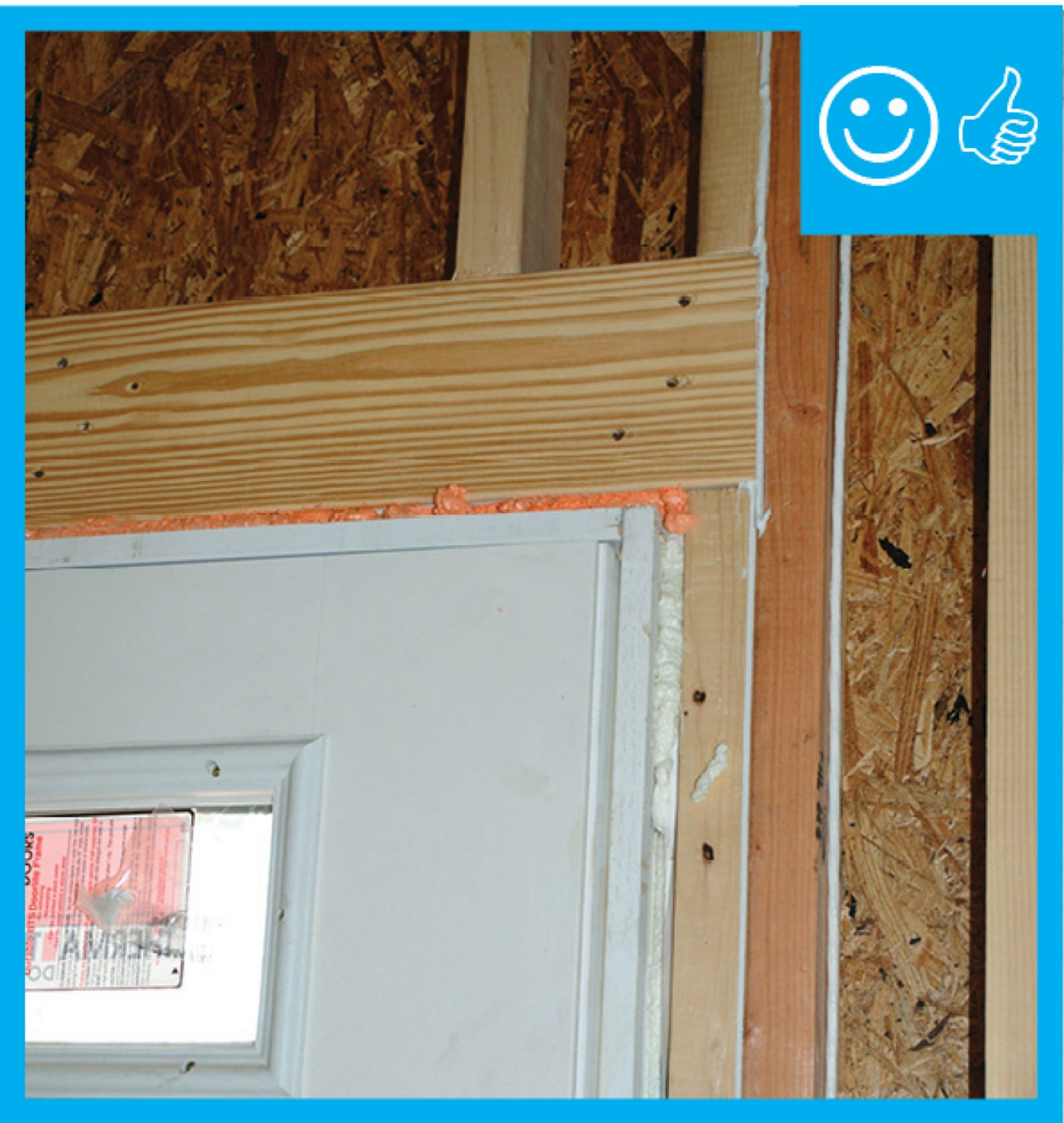
In areas prone to high winds and hurricanes, double vertical “jack trim” and horizontal “header” and “sill” studs are recommended on all sides of window and door openings.
Image
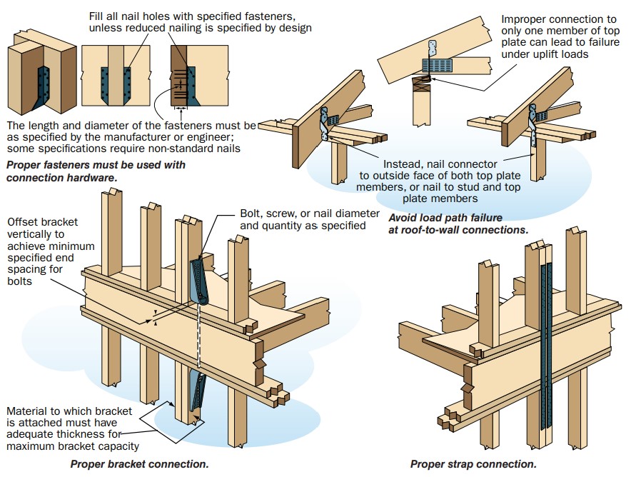
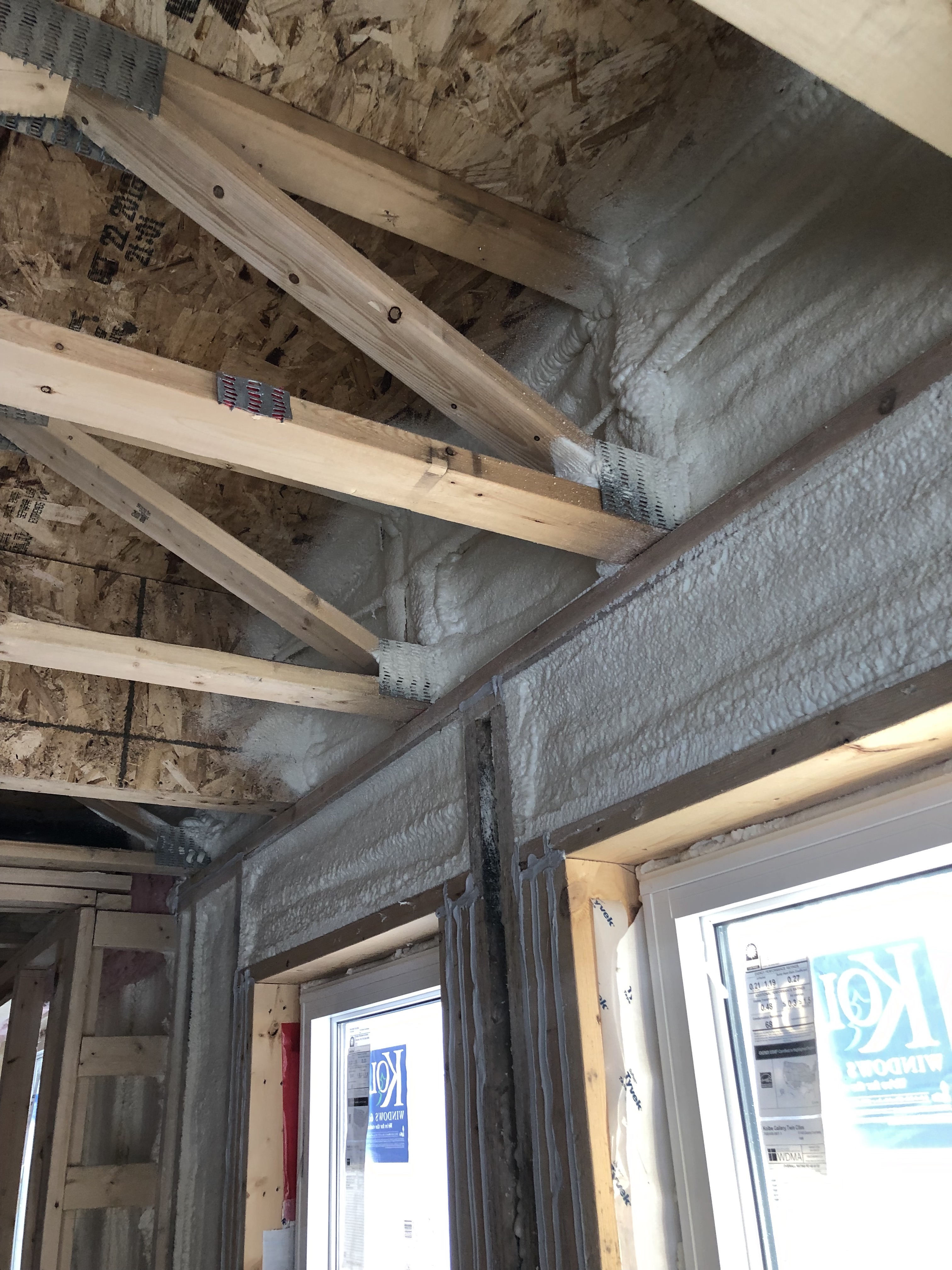
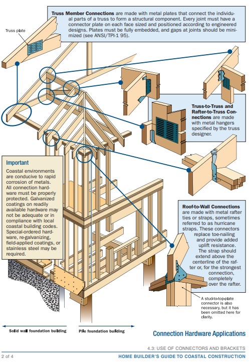
In high-wind regions, special hardware is used for most framing connections; toe-nailing is not acceptable.
Image
Image

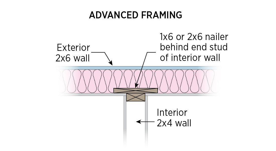
Installing ladder blocking at interior-exterior wall intersections rather than three solid studs in the exterior wall as the supporting surface allows room for insulation in the exterior wall.
Image
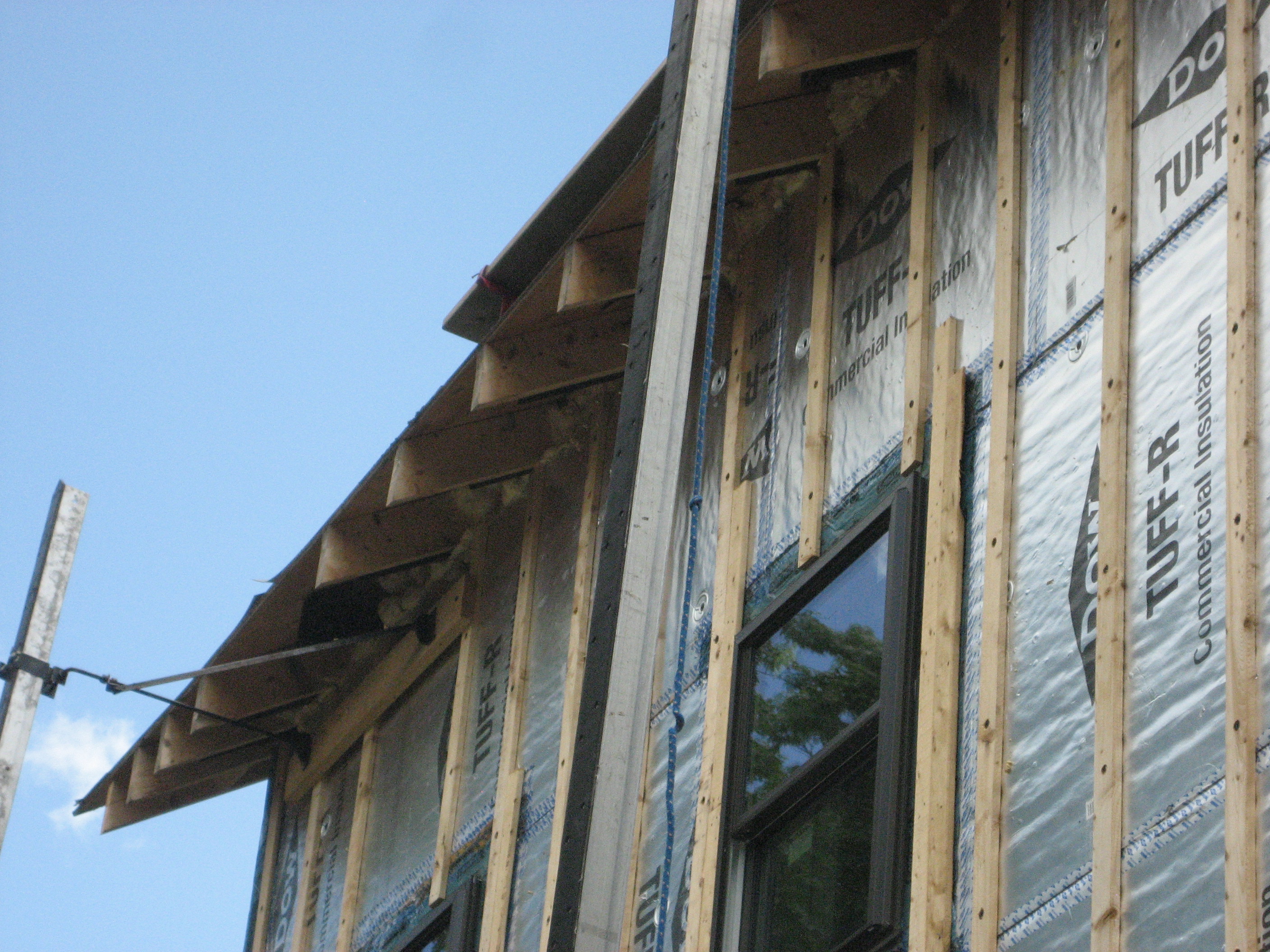
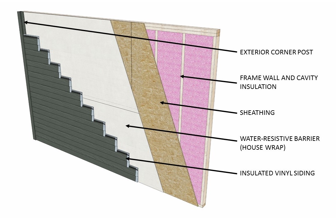
Insulating sheathing is extended up to the roof rafters and sealed around the framing with spray foam as part of this exterior wall retrofit
Image

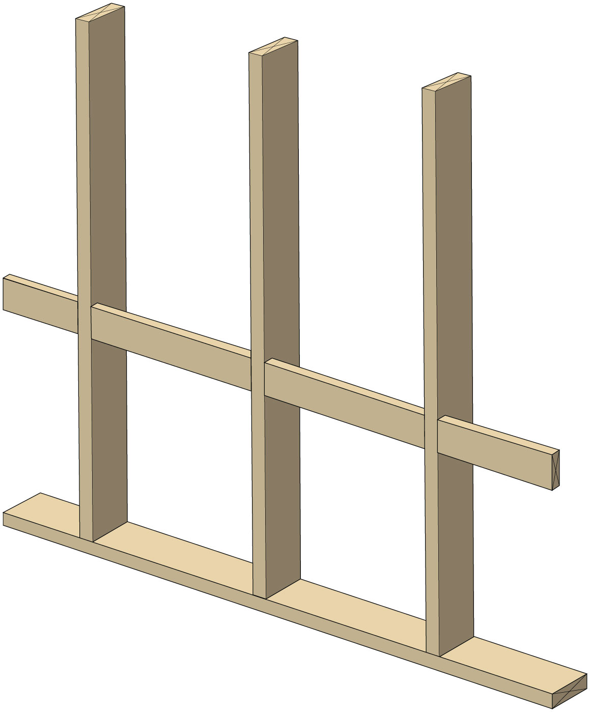
Interior non-load bearing walls are 2x4 studs spaced 24-inchon- center, can have non-structural connectors
Image

Interior wall attached with top plate metal connector, drywall clips support drywall, plan view
Image

Interior wall attached with top plate metal connector, drywall clips support drywall, side view
Image
Image

Image
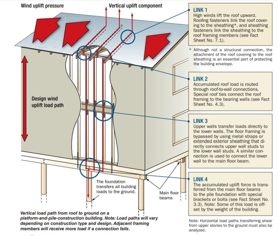
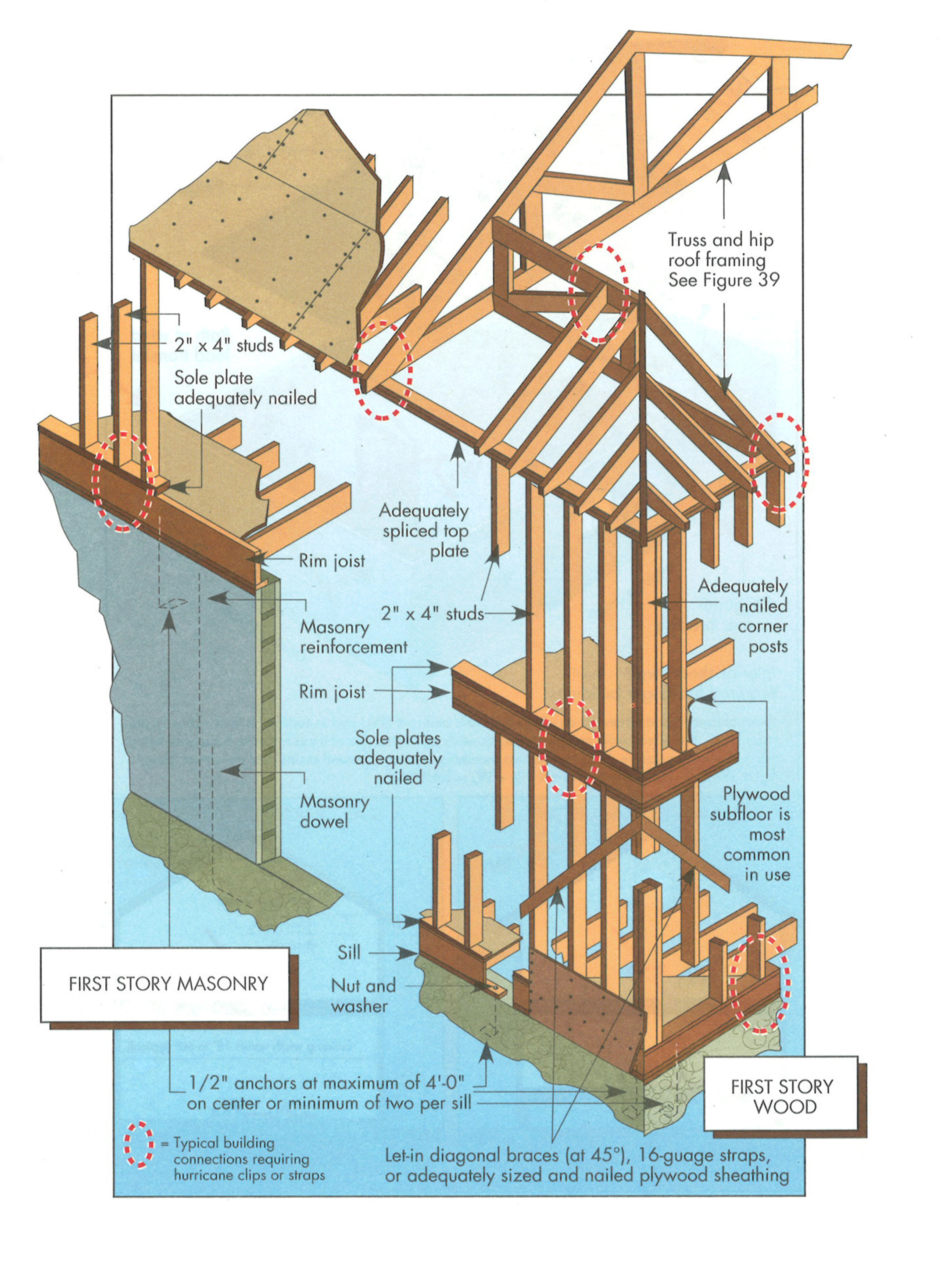
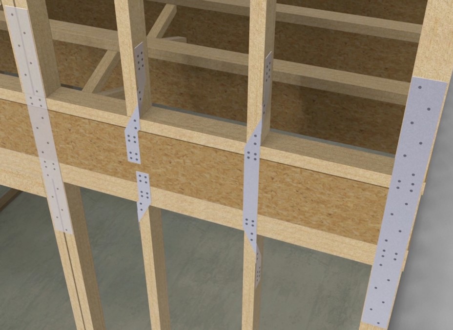
Key connection points for a continuous load path for earthquake and high wind disaster resistance
Image
Image
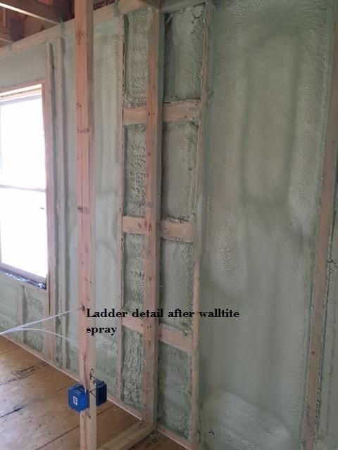
Ladder blocking where interior and exterior walls intersect uses less wood and provides more room for insulation than stacking studs in the exterior wall to nail the interior wall to.
Image

Image

Image
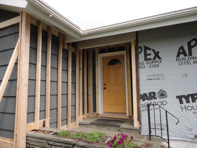
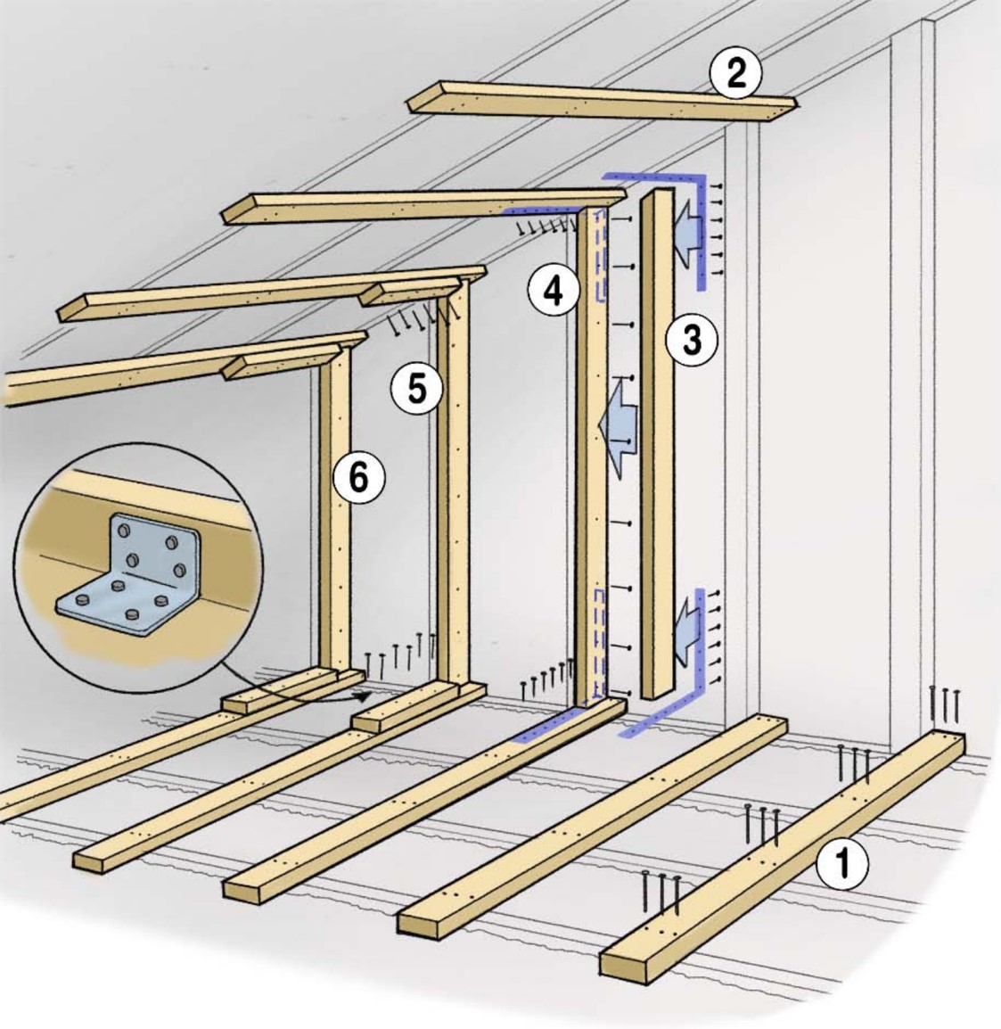
Ledger board, metal brackets, and vertical 2x4s have been installed in preparation for exterior spray foam in this retrofit exterior wall insulation technique
Image

Image
Image
Image
Image

Image
Reduce thermal bridging in hot climate zones by using an intersecting exterior wall framing technique as shown here.
Image

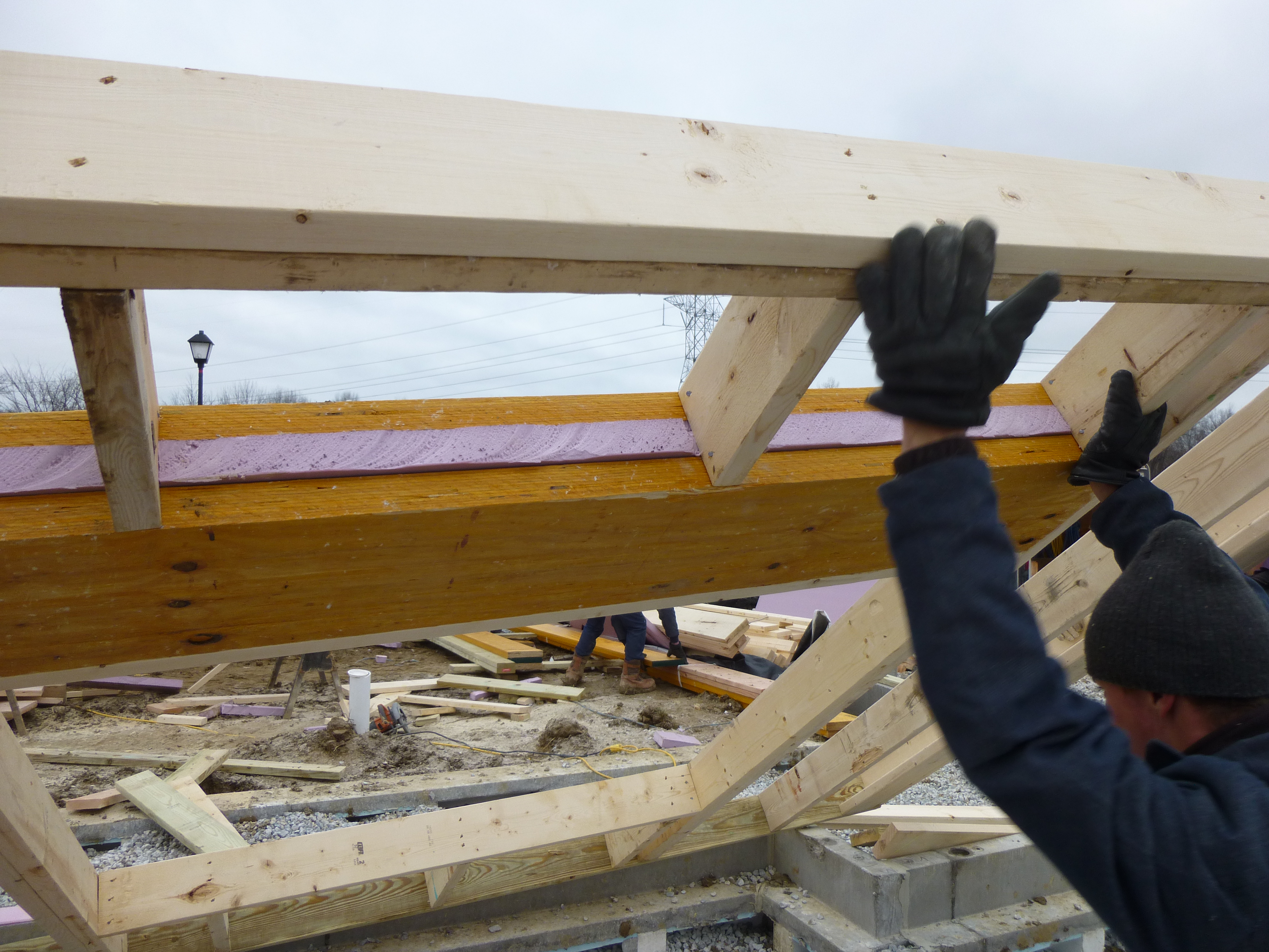
Right - A continuous load path connects the roof and wall framing to the foundation.
Image

Right - A floor-to-floor hold down can be installed as a retrofit without removing the siding.
Image
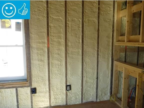
Right - Closed-cell spray foam insulation fills the wall cavities of the exterior walls in this home retrofit
Image
Image

Right - Engineered portal frames are used for wall bracing to resist wind and earthquake loads.
Image
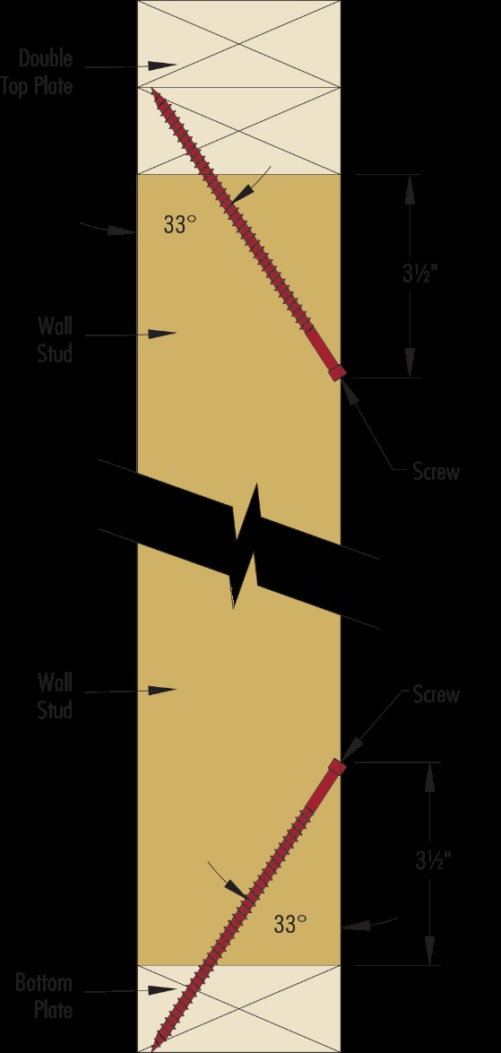
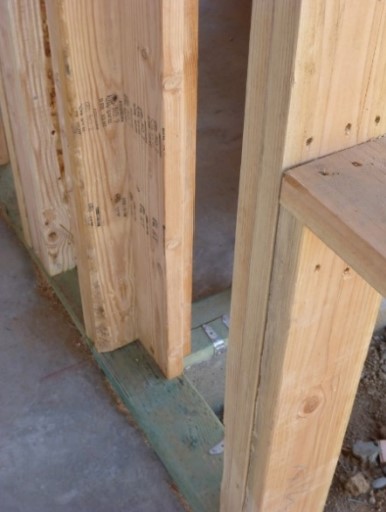
Right - Engineered structural screws are installed to secure a stud to a top and bottom plate for increased hurricane or seismic resistance.
Image
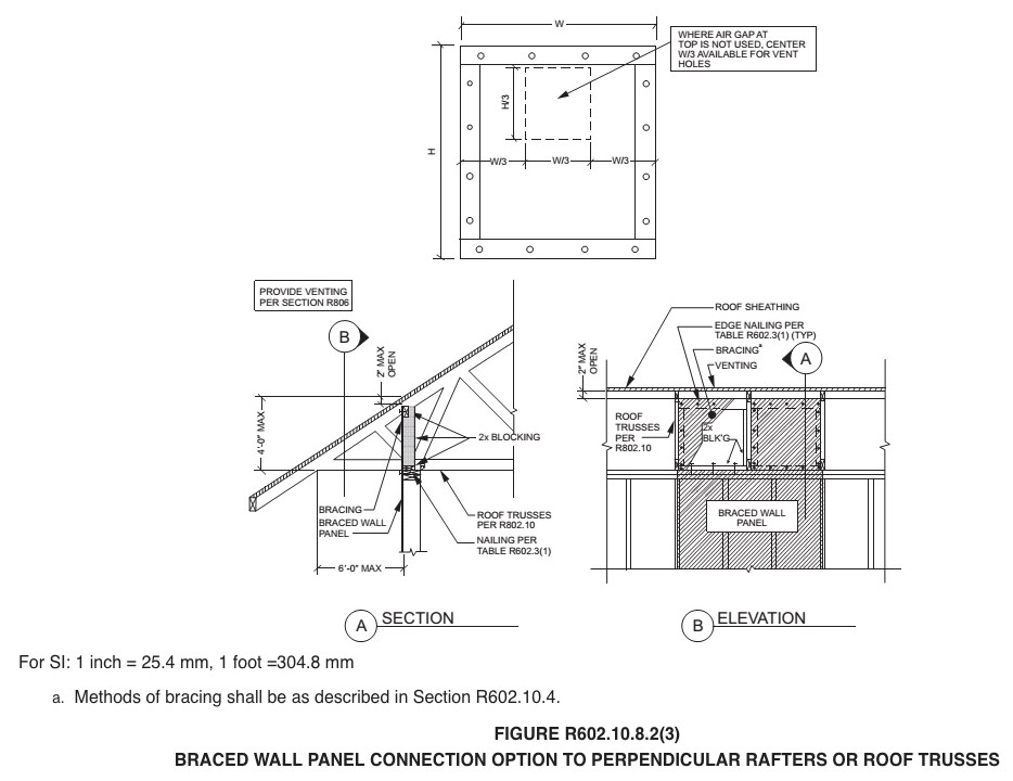
Right - Installation steps for the L-bent strap method of bracing a gable end wall
Image
Right - Metal connectors provide uplift resistance at the rim joist between floors in new construction for a continuous load path.
Image
Right - Metal connectors provide uplift resistance at the stud-to-bottom plate connection in new construction for a continuous load path.
Image
Right - New flashing has been installed to complete the air and water control layers at the window openings of this wall retrofit that includes insulating the wall cavities with spray foam
Image
Right - Spray foam fills the walls and rim joists to air seal and insulate while caulk seals the framing joints.
Image

Right - The wall framing is connected to roof framing with metal ties for hurricane-resistant construction.
Image
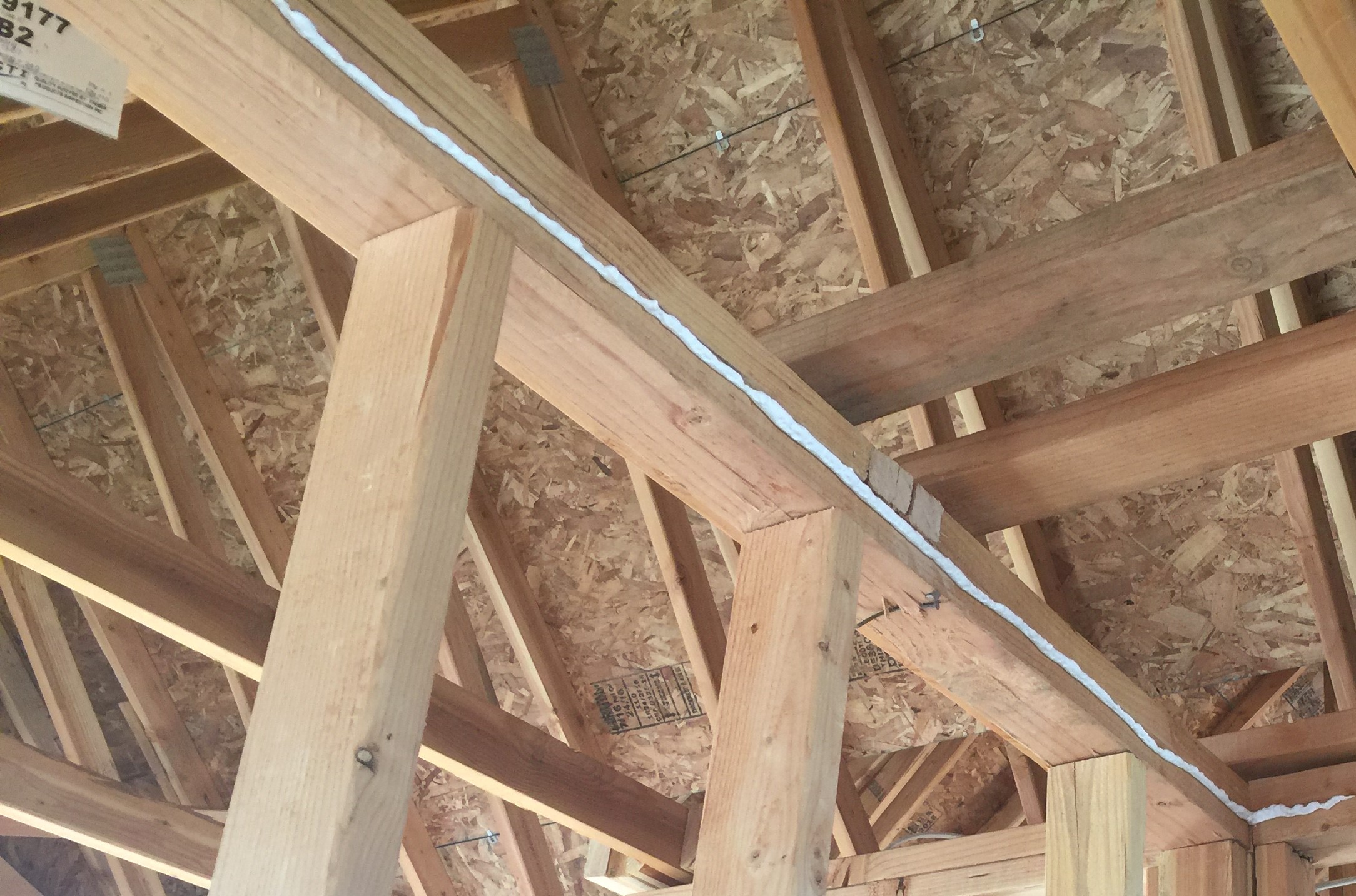
Right – A bead of sealant will form an airtight gasket between the top plate and drywall.
Image
Image

Right – A gap separates the two wall layers in this double-stud wall assembly allowing room for insulation to stop thermal bridging between the inner and outer wall
Image
Image
Right – An existing gable wall is reinforced with horizontal braces that butt up to the gable end wall and connect back to multiple trusses; retrofit studs make full contact with the wall and the compression blocks and are connected to the horizontal brac
Image
Image
Right – Appropriate use of framing members to support double windows and additional cripples for drywall purposes
Image
Image
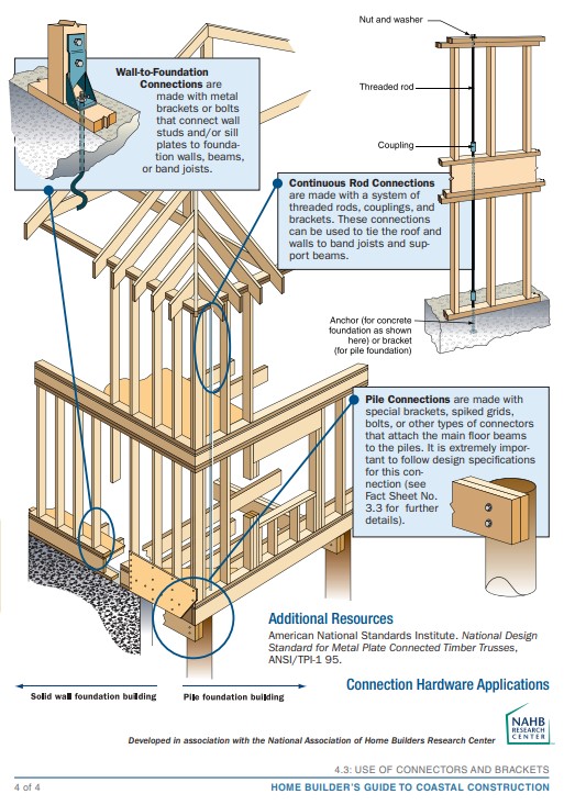
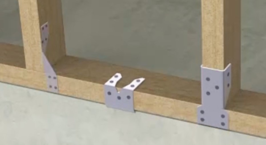
Right – Examples of wall stud to sill plate and foundation and wall rod connectors and brackets.