Showing results 1 - 47 of 47
Image
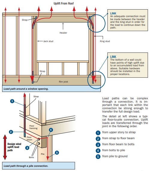
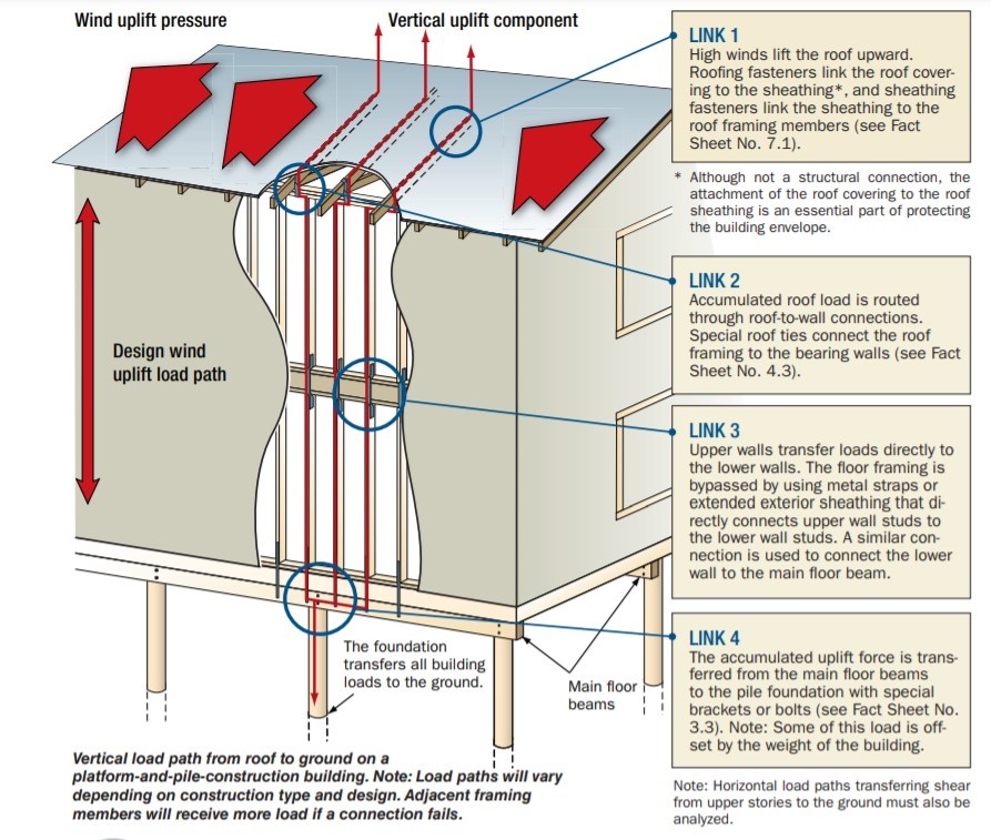
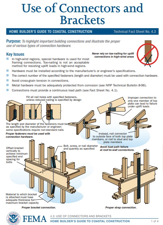
A continuous load path uses structural connections to transfer horizontal and vertical loads from the roof to the foundation to help keep the building intact in high-wind and seismic events
Image
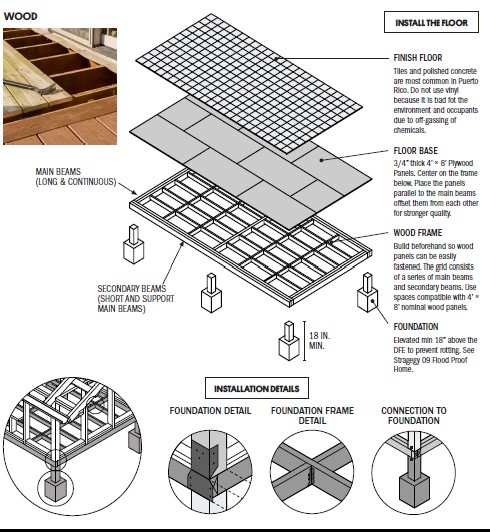
A raised wood pier foundation can raise the subfloor above the design flood elevation.
Image
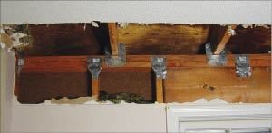
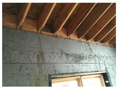
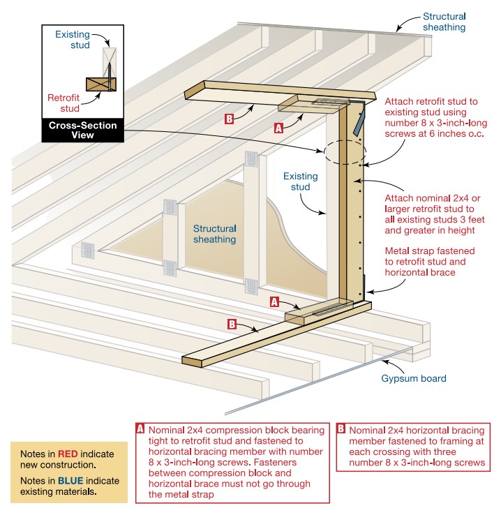
Add metal connectors to strengthen framing connections in an existing wall from inside the home by removing drywall.
Image
Image
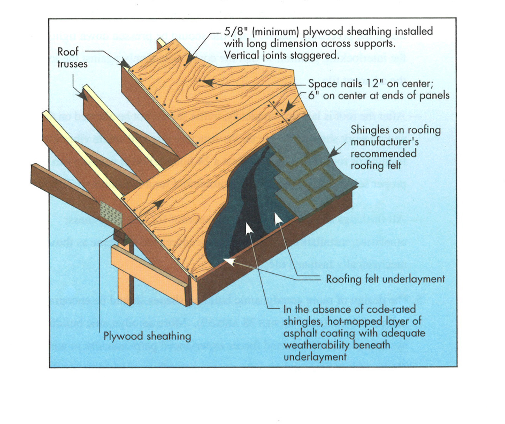
Composition shingle roofing system showing sheathing and hot-mopped underlayment
Image
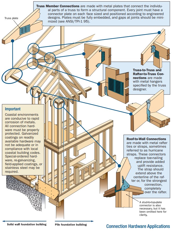
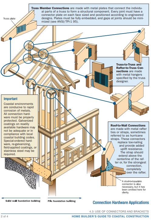
Connecting hardware helps tie the roof to the walls to ensure a continuous load path to improve a building’s resistance to high winds, floods, and earthquakes.
Image
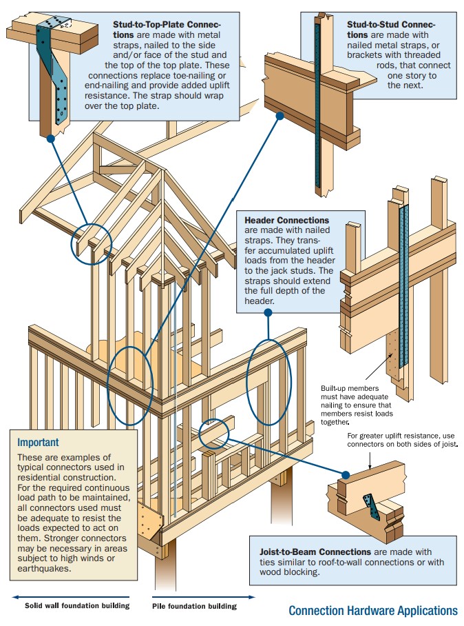
Connecting hardware helps tie the walls to the top plates and rim joists to ensure a continuous load path to improve a building’s resistance to high winds, floods, and earthquakes.
Image
Image
Image
Image
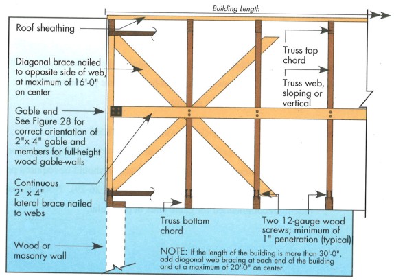
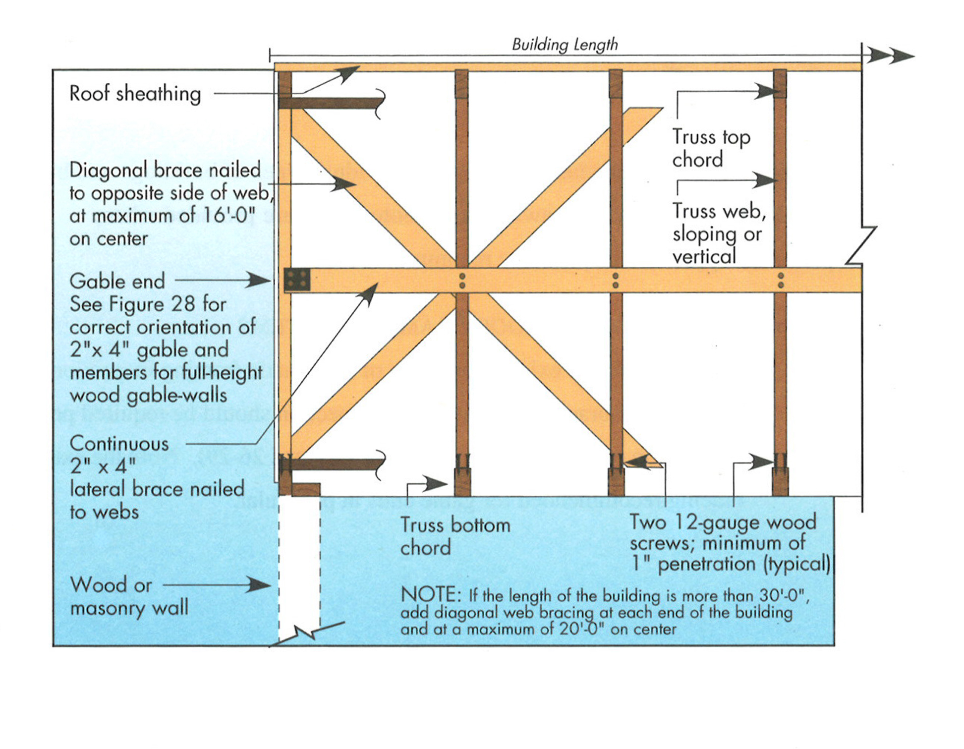
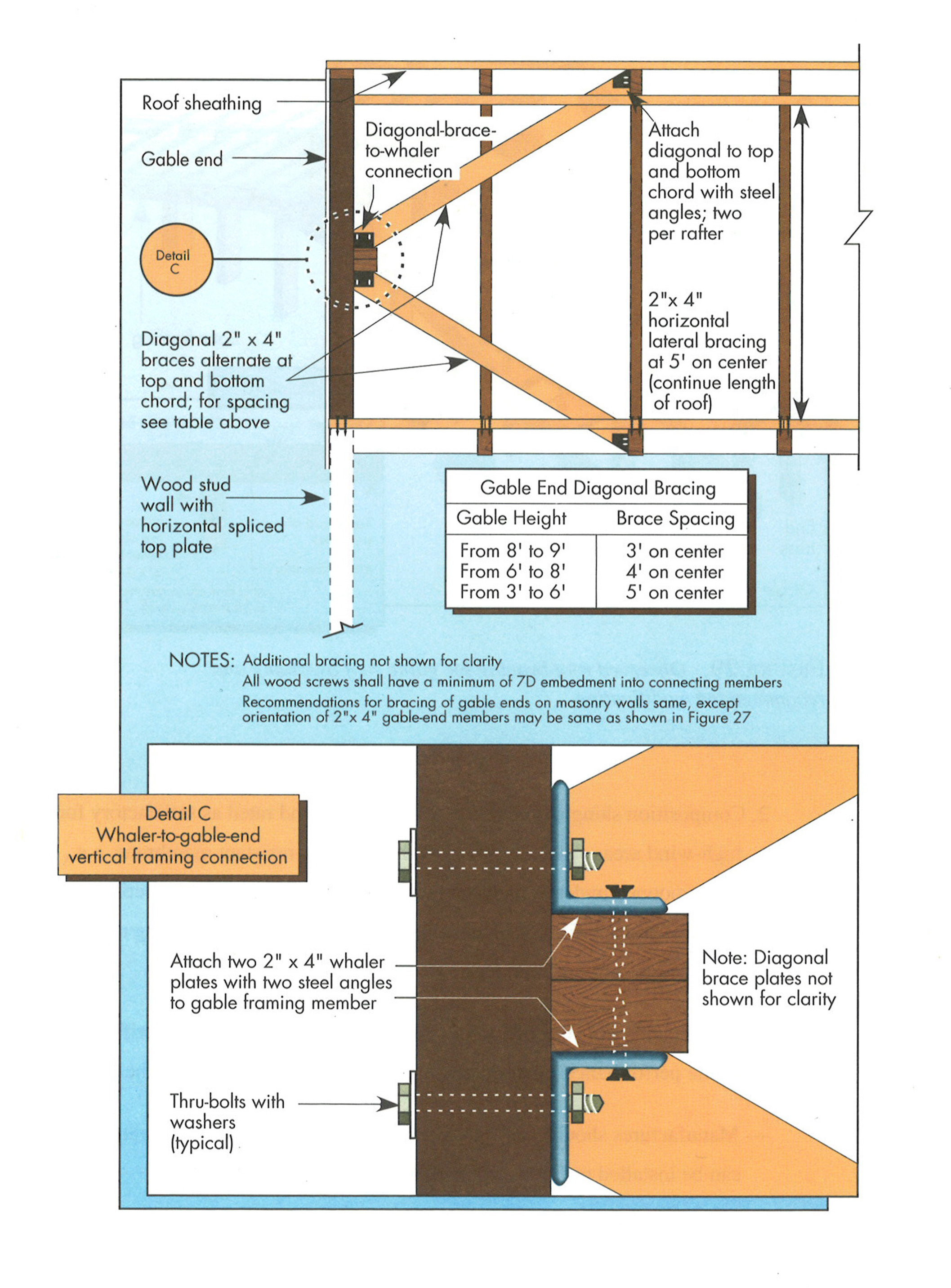
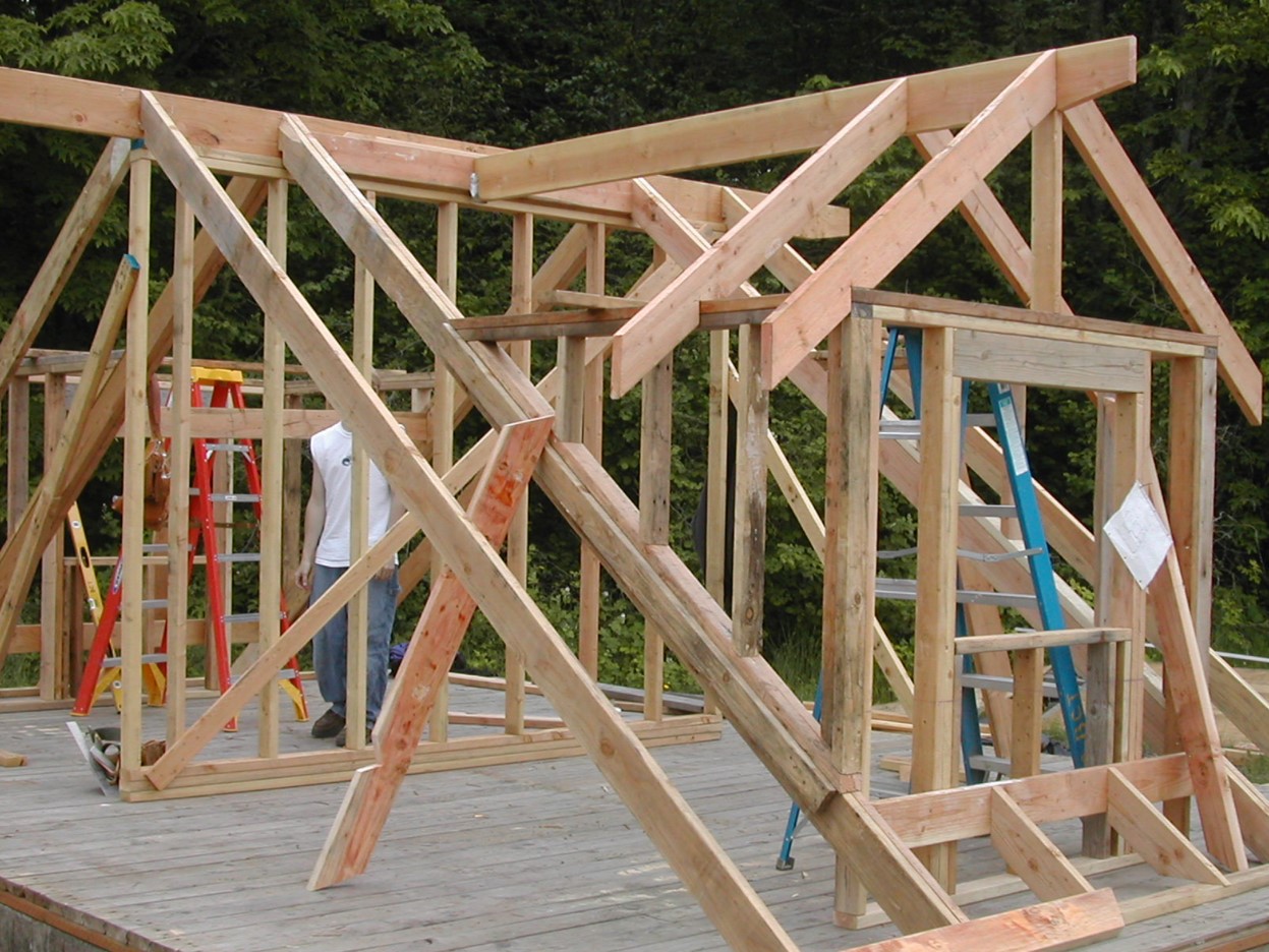
Example A of a gable truss and gable end wall bracing for a home in a hurricane region
Image

Example B of a gable truss and gable end wall bracing for a home in a hurricane region
Image
Image
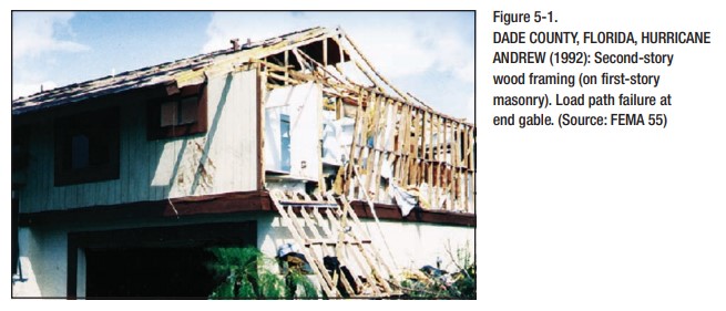
Improper continuous load path design lacking bracing results in the failure of gable end walls under high wind conditions.
Image
In areas prone to high winds and hurricanes, double vertical “jack trim” and horizontal “header” and “sill” studs are recommended on all sides of window and door openings.
Image
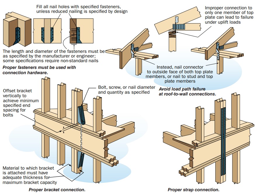
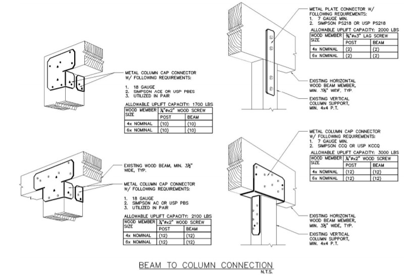
In high-wind regions, special hardware is used for most framing connections; toe-nailing is not acceptable.
Image
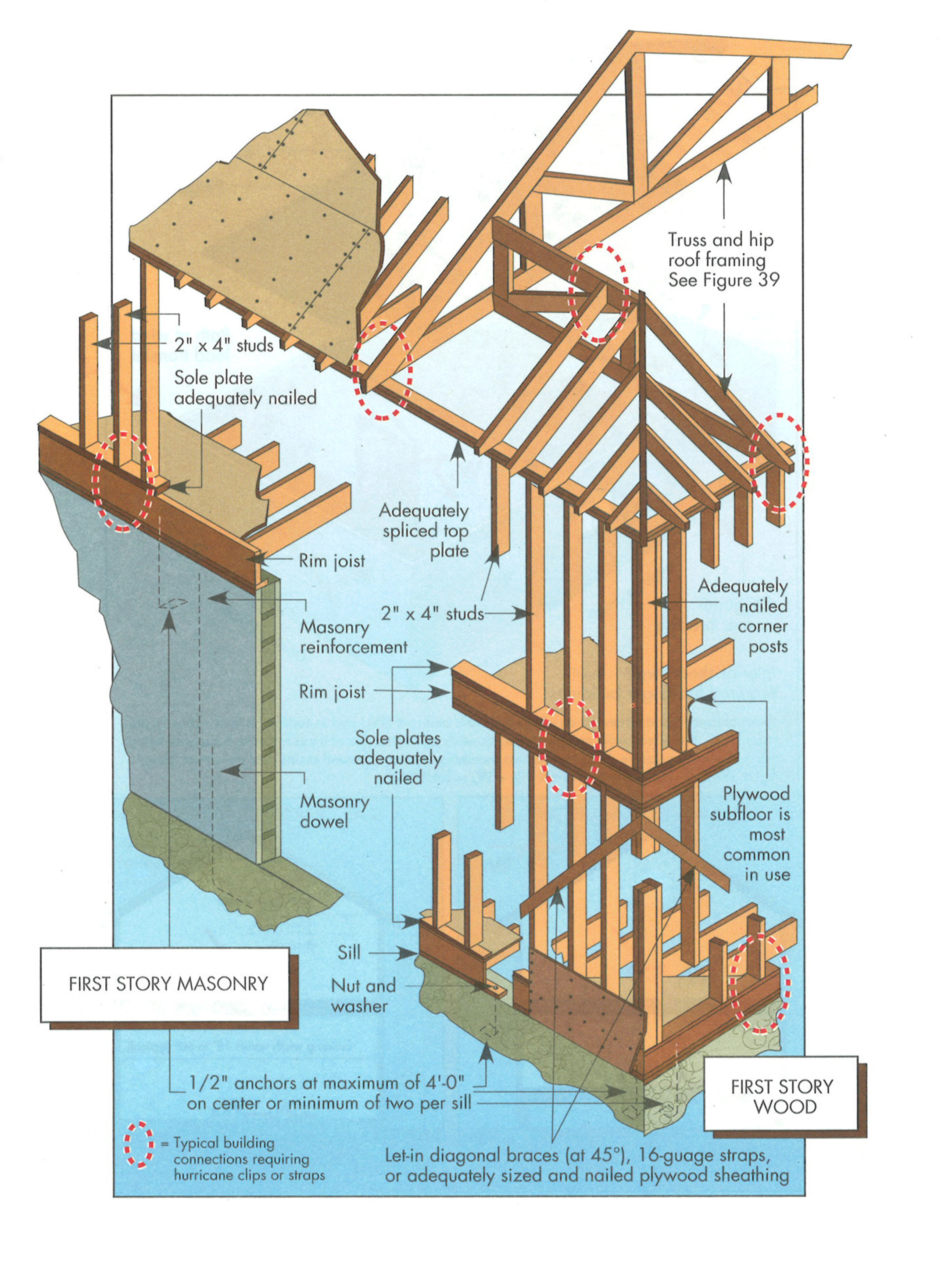
Key connection points for a continuous load path for earthquake and high wind disaster resistance
Image
Image
Image
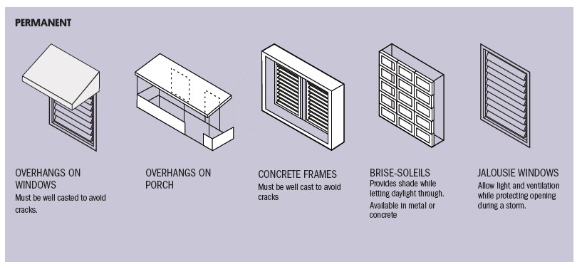
Permanent options for keeping sun off windows to minimize solar heat gain include permanent overhangs and awnings, frames, and louvers.
Image
Image

Image
Image

Right - A continuous load path connects the roof and wall framing to the foundation.
Image

Right - Engineered portal frames are used for wall bracing to resist wind and earthquake loads.
Image
Image
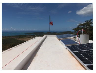
Right - This concrete roof is properly attached and reinforced to withstand hurricane winds.
Image
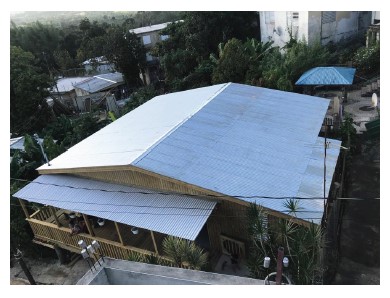
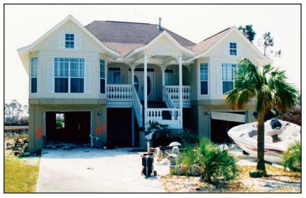
Right - This roof has a low gable and is secured to the wall framing to resist wind uplift.
Image
Image
Image
Image
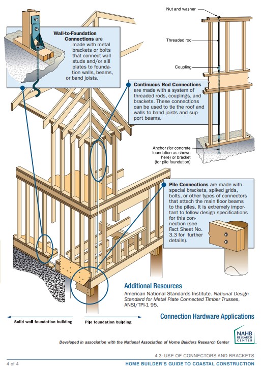
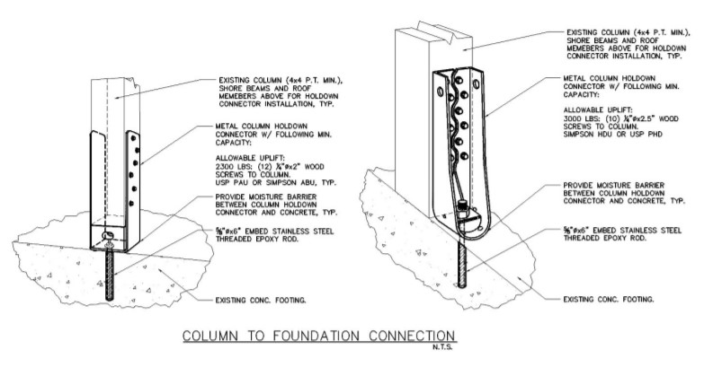
Right – Examples of wall stud to sill plate and foundation and wall rod connectors and brackets.
Image
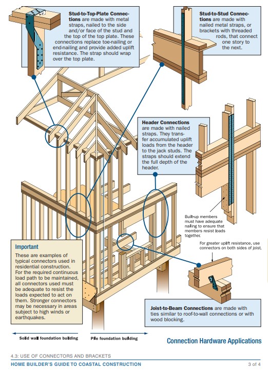
Right – Examples of wall stud to top plate and stud to rim joist framing connectors and brackets.
Image
Image
Image
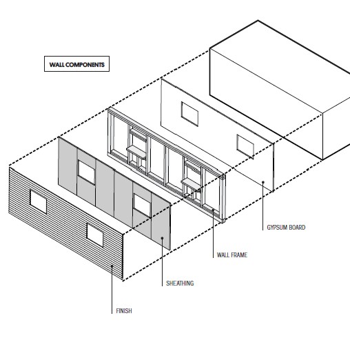
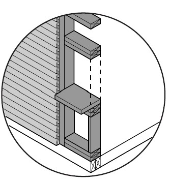
The components of a framed wall include from inside to out: gypsum, wood studs, OSB or plywood sheathing, and siding.
Image
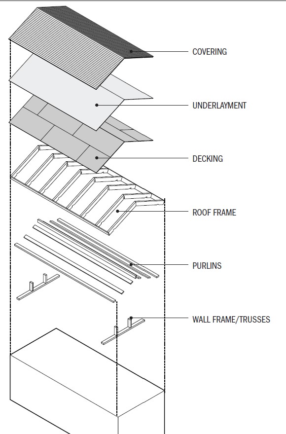
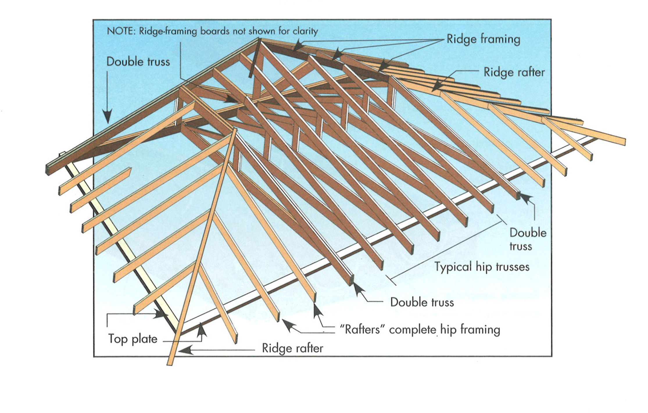
The components of a roof include the rafter framing or trusses, purlins, plywood roof decking, underlayment, and the roof covering.
Image
Image
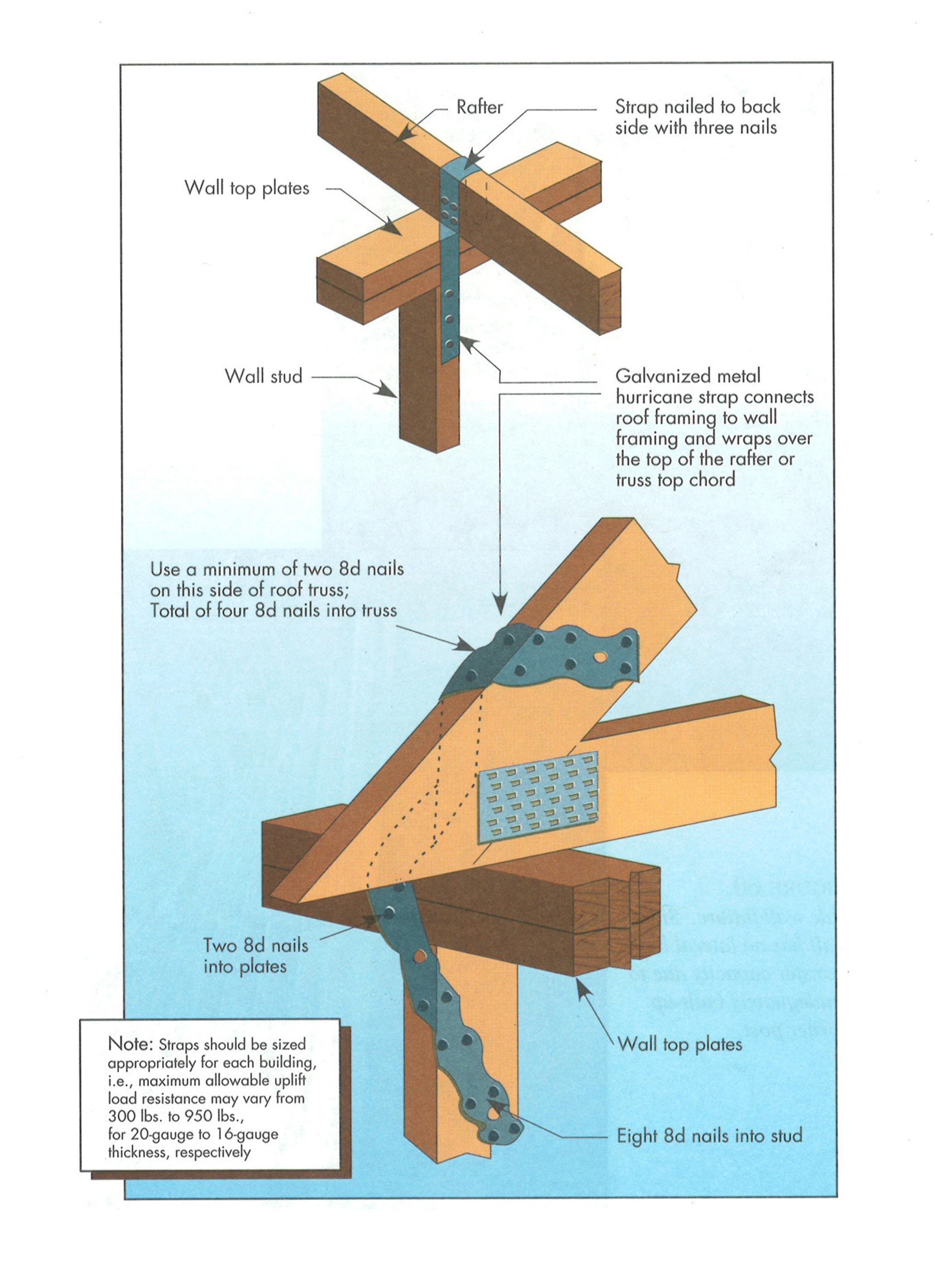
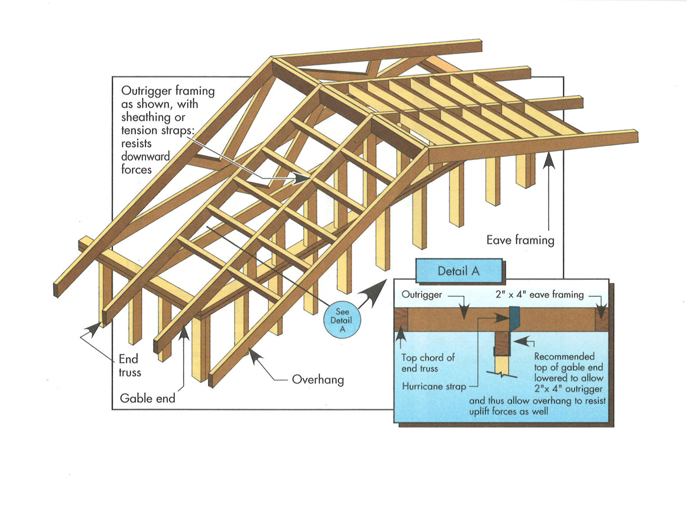
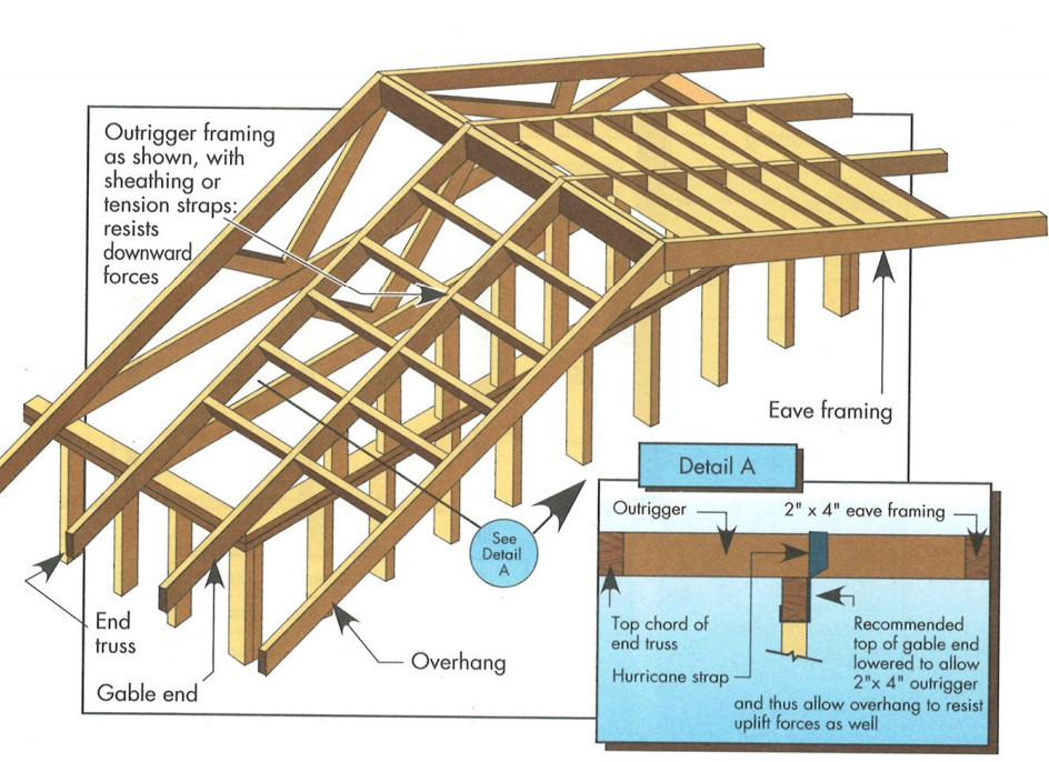
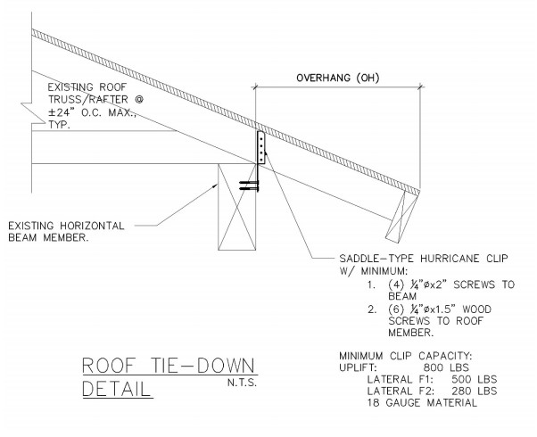
Typical hurricane strap to roof framing detail. Rafter or prefabricated roof truss.
Image

Image

Image
Wrong - Framing a dormer using only toe nailing and end nailing is not acceptable in areas subjected to high winds, hurricanes, or earthquakes.
Image

Image
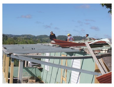
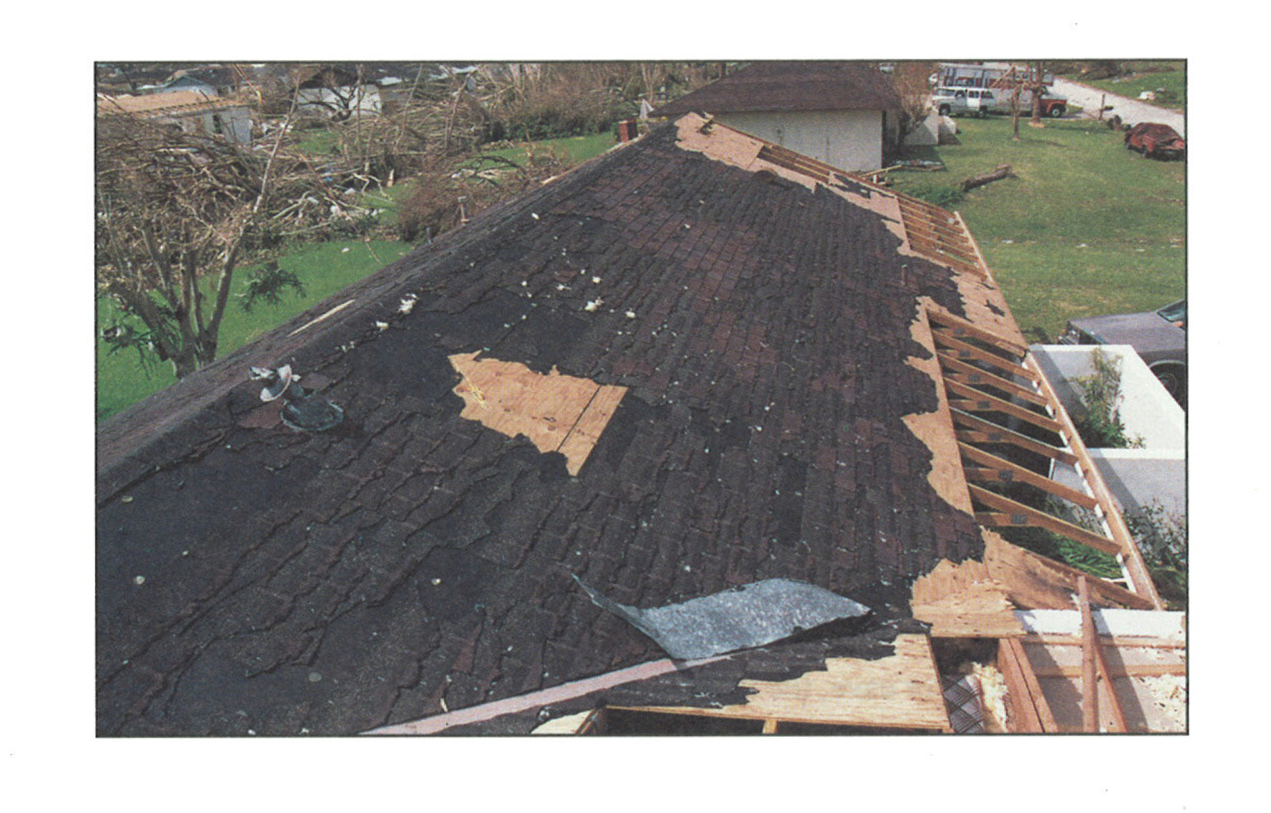
Wrong - This roof failed in high winds due to lack of metal attachments to the framing.
Image

Wrong – The gable end wall failed because the rigid foam sheathing was not backed up by plywood or OSB.
Image

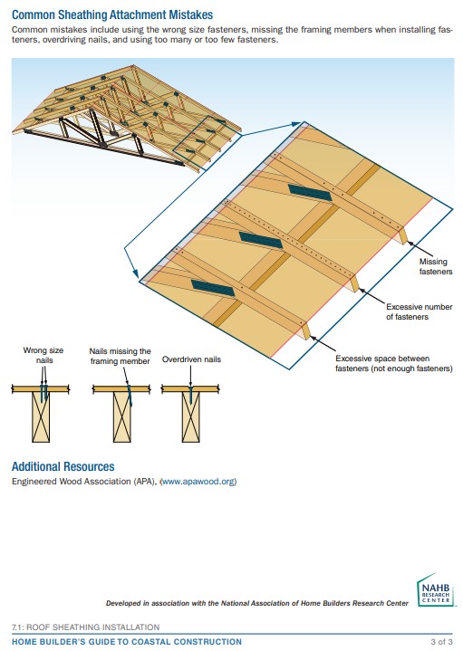
Wrong – The roof sheathing was inadequately fastened and gave way causing the gable end wall to fail
Image
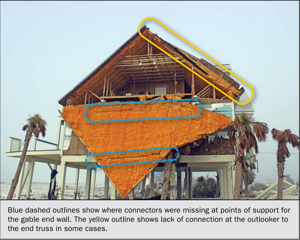
Wrong – This gable end wall failed because connectors were missing at points of support (blue circles) and the outlookers were not connected to the end truss (yellow circle)