Showing results 101 - 150 of 211
Image
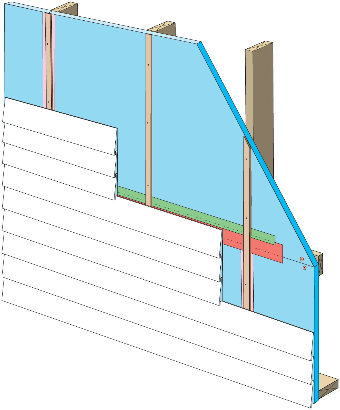
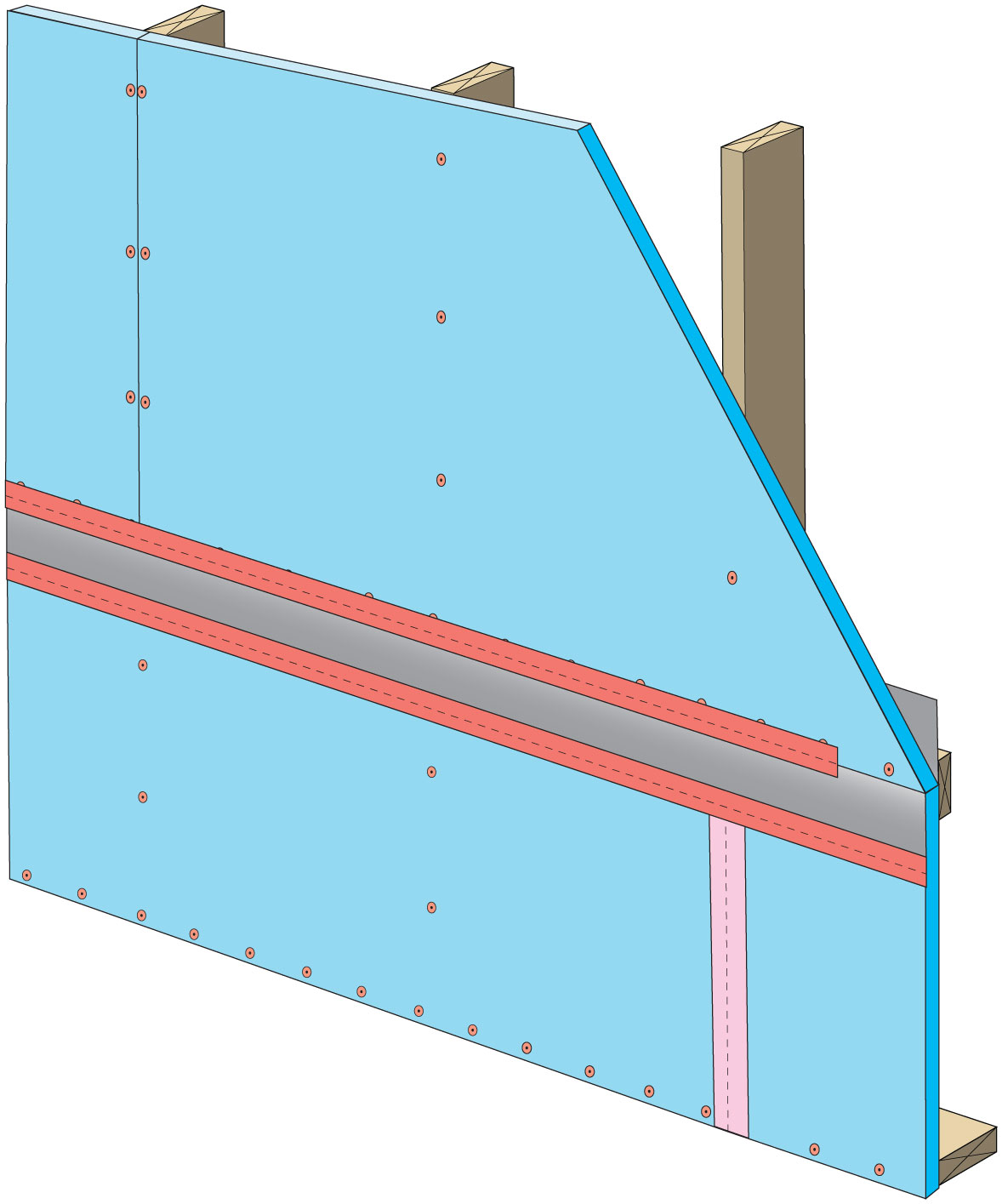
Rigid foam insulation can serve as the drainage plane when all seams are taped. Furring strips provide an air gap behind the cladding.
Image
Image
Image
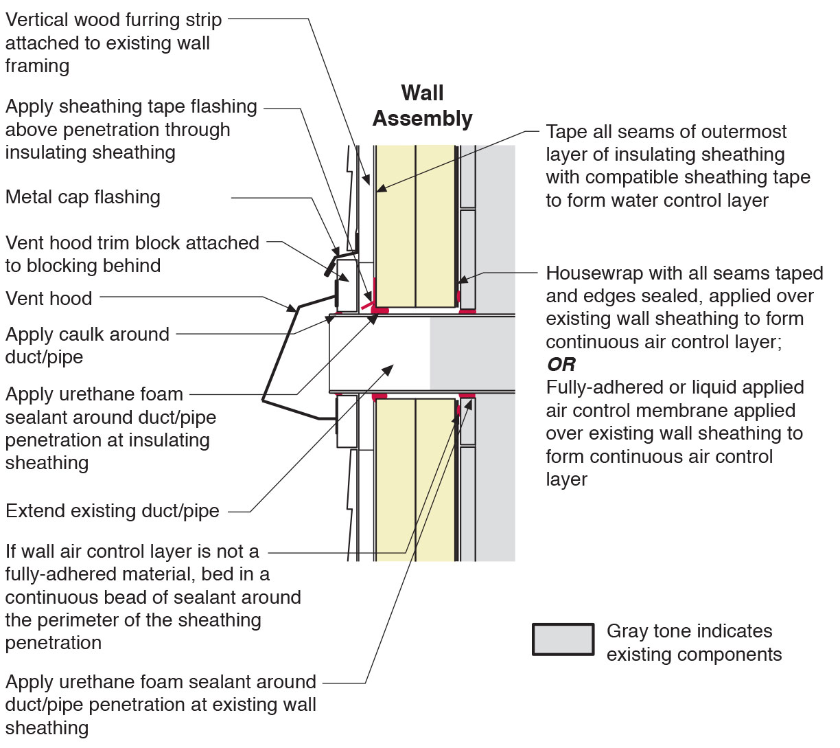
Section view of duct or pipe penetration through exterior wall showing flashing and air sealing details
Image
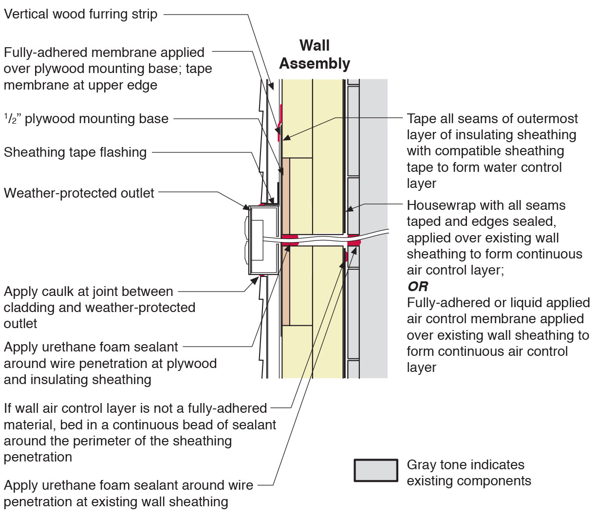
Section view of electric box installation in exterior wall showing flashing and air sealing details
Image

Spray foam adhesive provides an extra water resistant layer to the joints and seams on the inside of attics.
Image

Image
Image
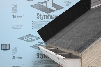
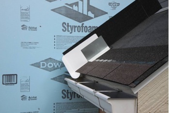
Step 1. Apply roof underlayment over roof deck and up the sidewall over the rigid foam insulation
Image
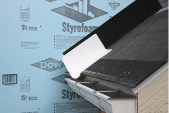
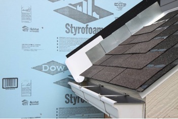
Step 2. Install shingle starter strip then kick-out diverter as first piece of step flashing.
Image
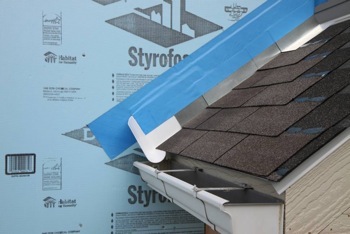
Step 3. Place the first shingle and the next section of sidewall flashing over upper edge of diverter
Image
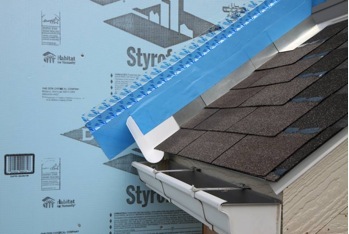
Step 4. Install remaining sidewall flashing, appropriate counter flashing, and shingles
Image
Step 5. Apply self-adhesive flashing over top edge of the wall flashing, diverter, and rigid foam insulation
Image
Image
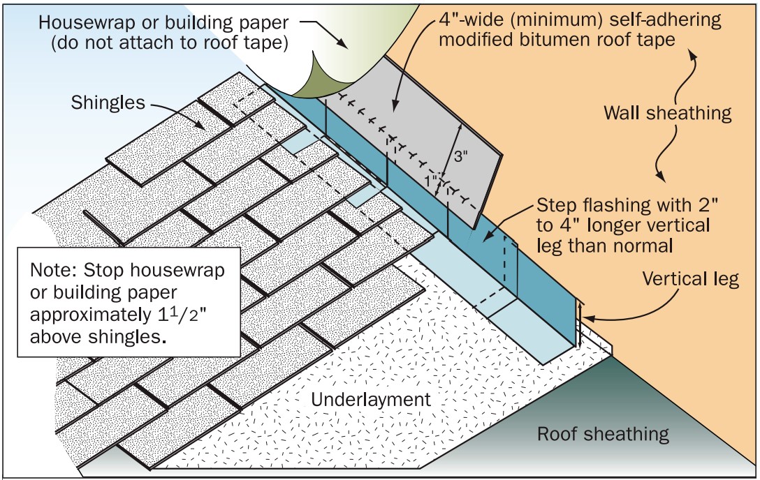
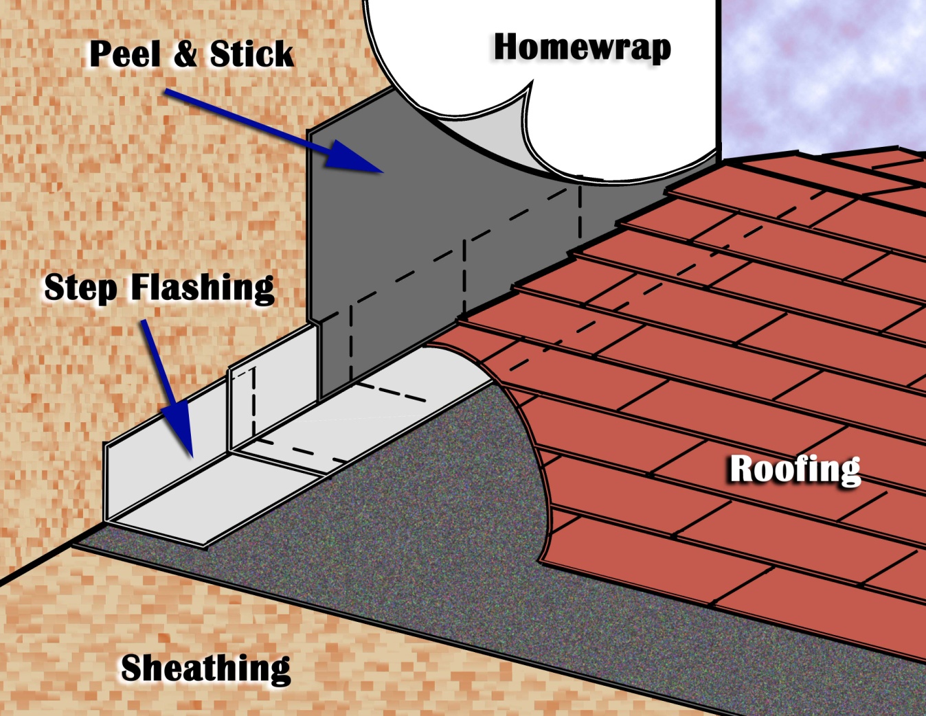
Step and kick-out flashing at all roof-wall intersections extending ≥ 4 in. on wall surface above roof deck and integrated with drainage plane above
Image
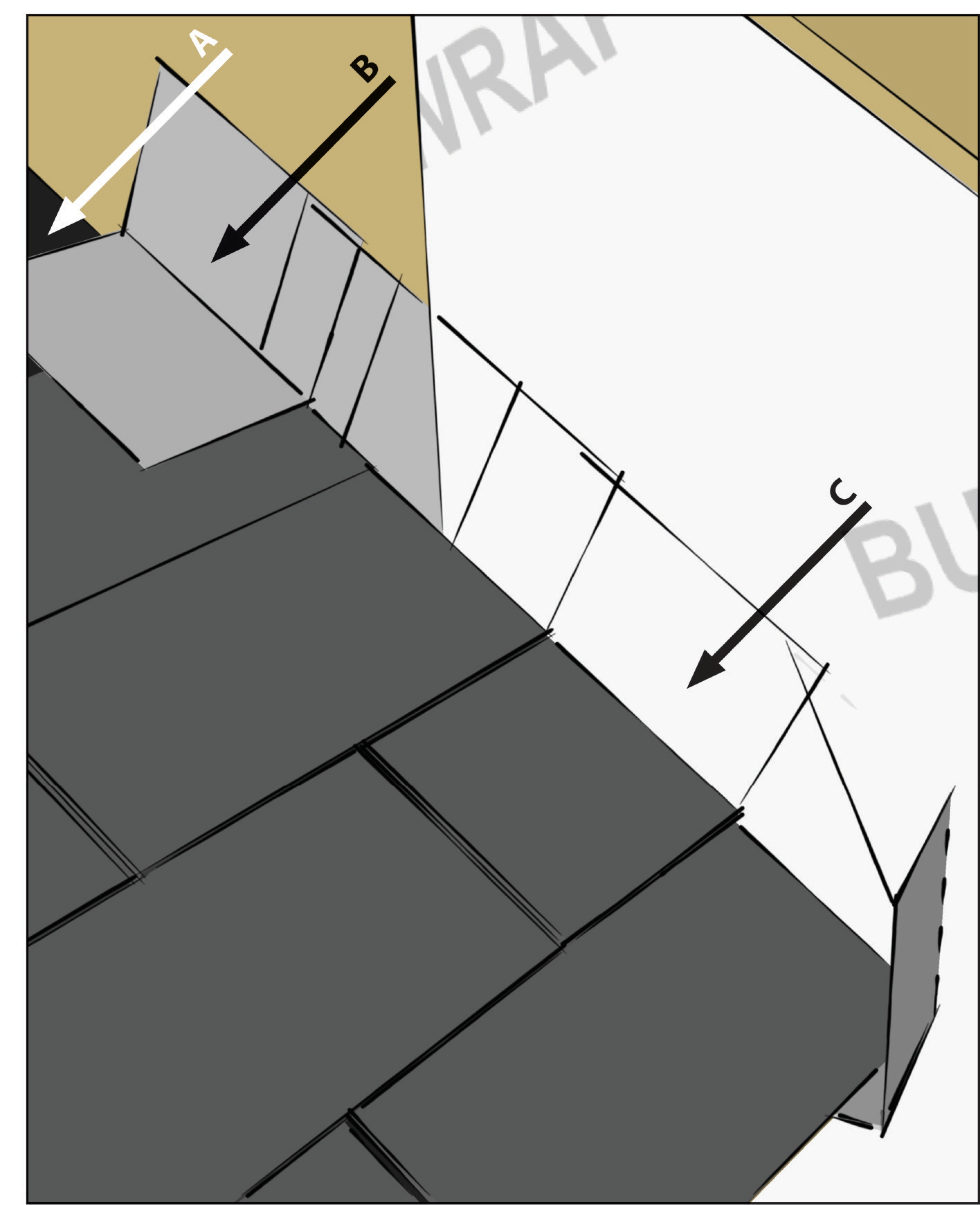
Strips of roofing membrane are used to flash around a skylight on a flat roof retrofit
Image
Image
Image
Tape the joint between the top insulation sheet and the Z-flashing with 2" wide tape to improve air tightness
Image
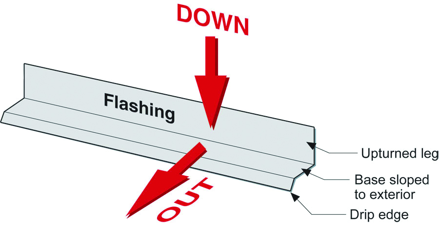
The “down” and “out” approach to flashing – metal flashing directs water down and out of building assemblies
Image

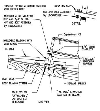
The blocking is completely flashed with roofing membrane before the PV rack hardware is attached on a flat roof
Image

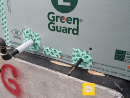
The fluid-applied asphalt coating provides a weather-resistant, moisture resistant layer around the house, serving as a continuous drainage plane and flashing for window and door openings.
Image
The home is sheathed with rigid foam insulation and all seams and holes are taped to provide a continuous air barrier.
Image
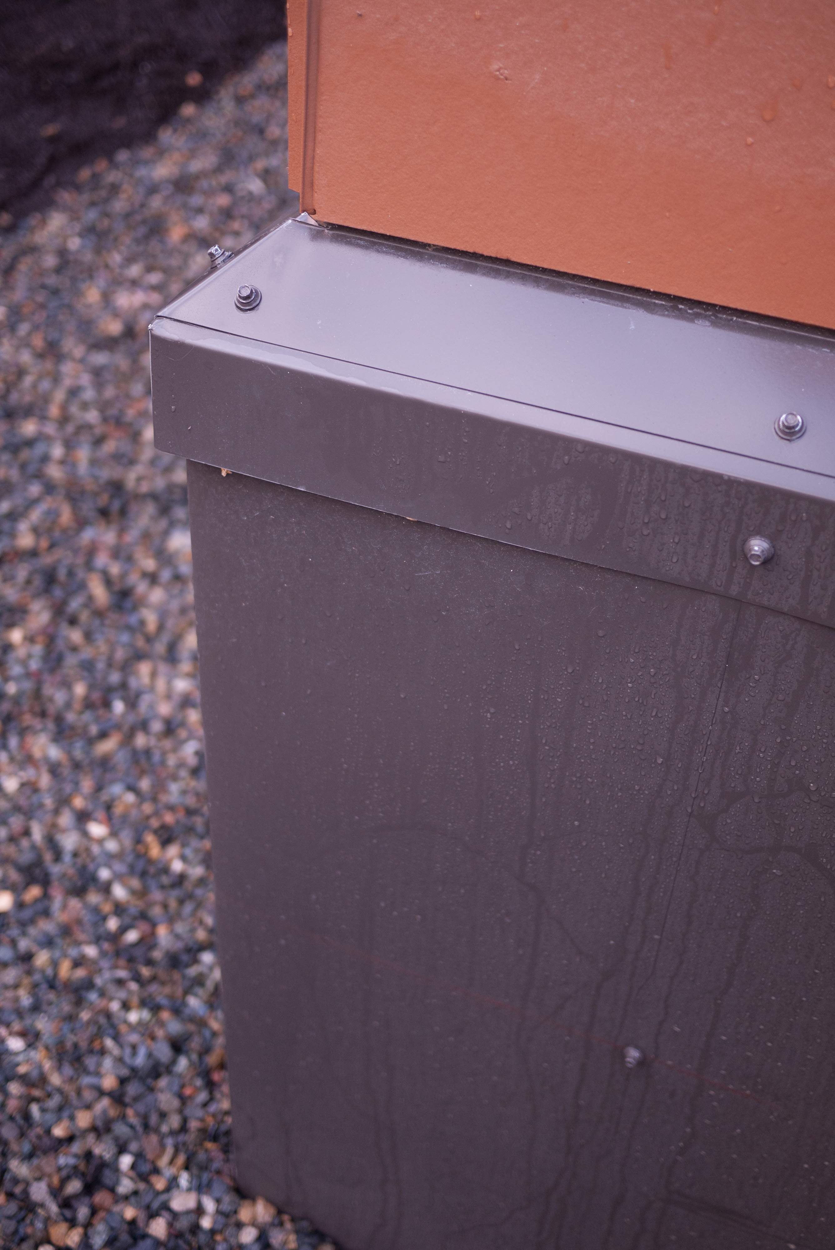
The ICF foundation wall of this home is covered with metal flashing before the siding is installed.
Image

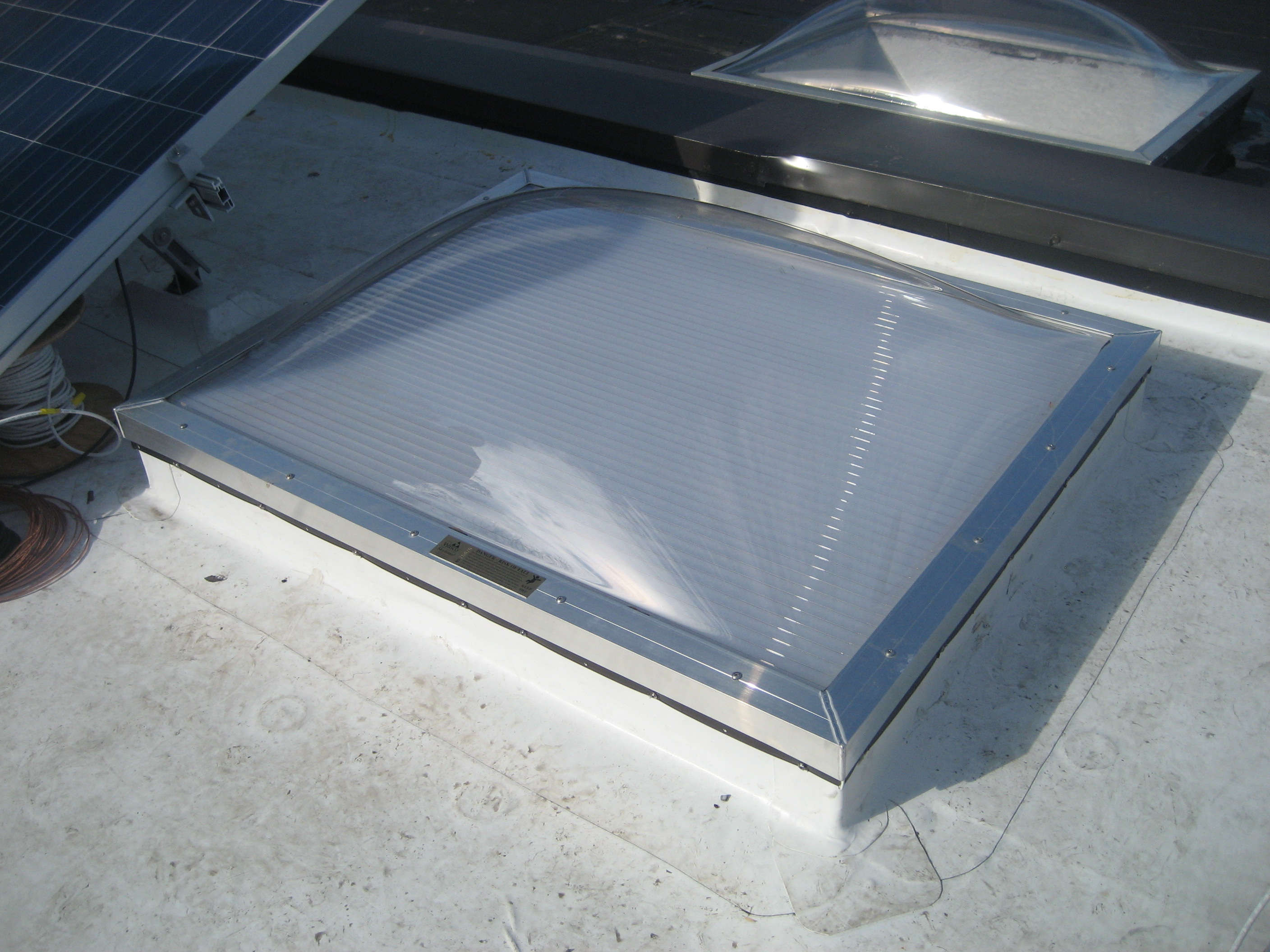
The retrofitted flat roof has PV panels and walking mats installed over the roofing membrane
Image
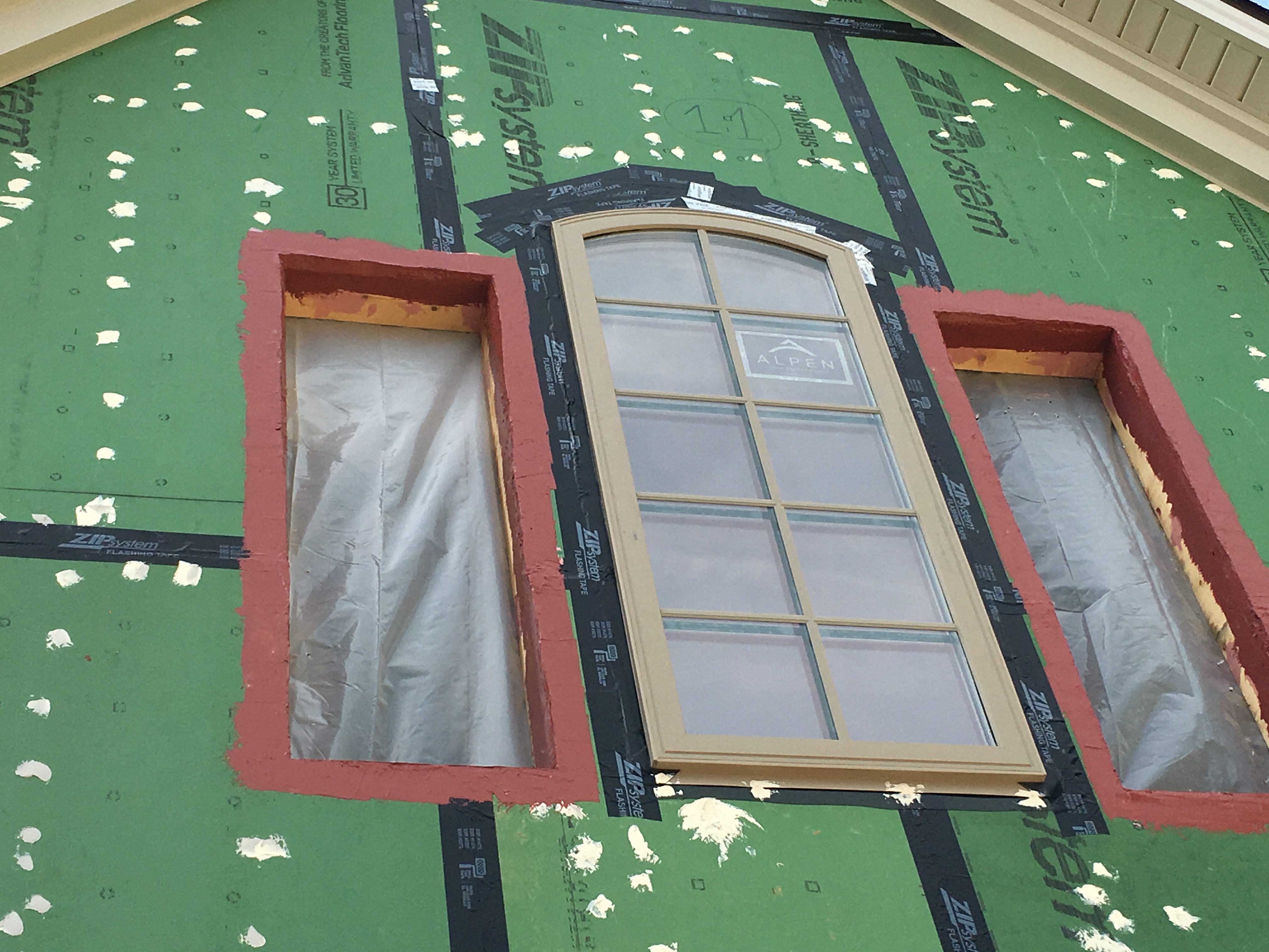
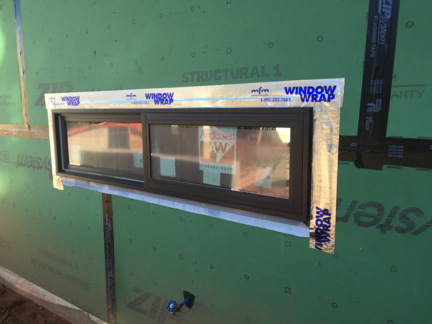
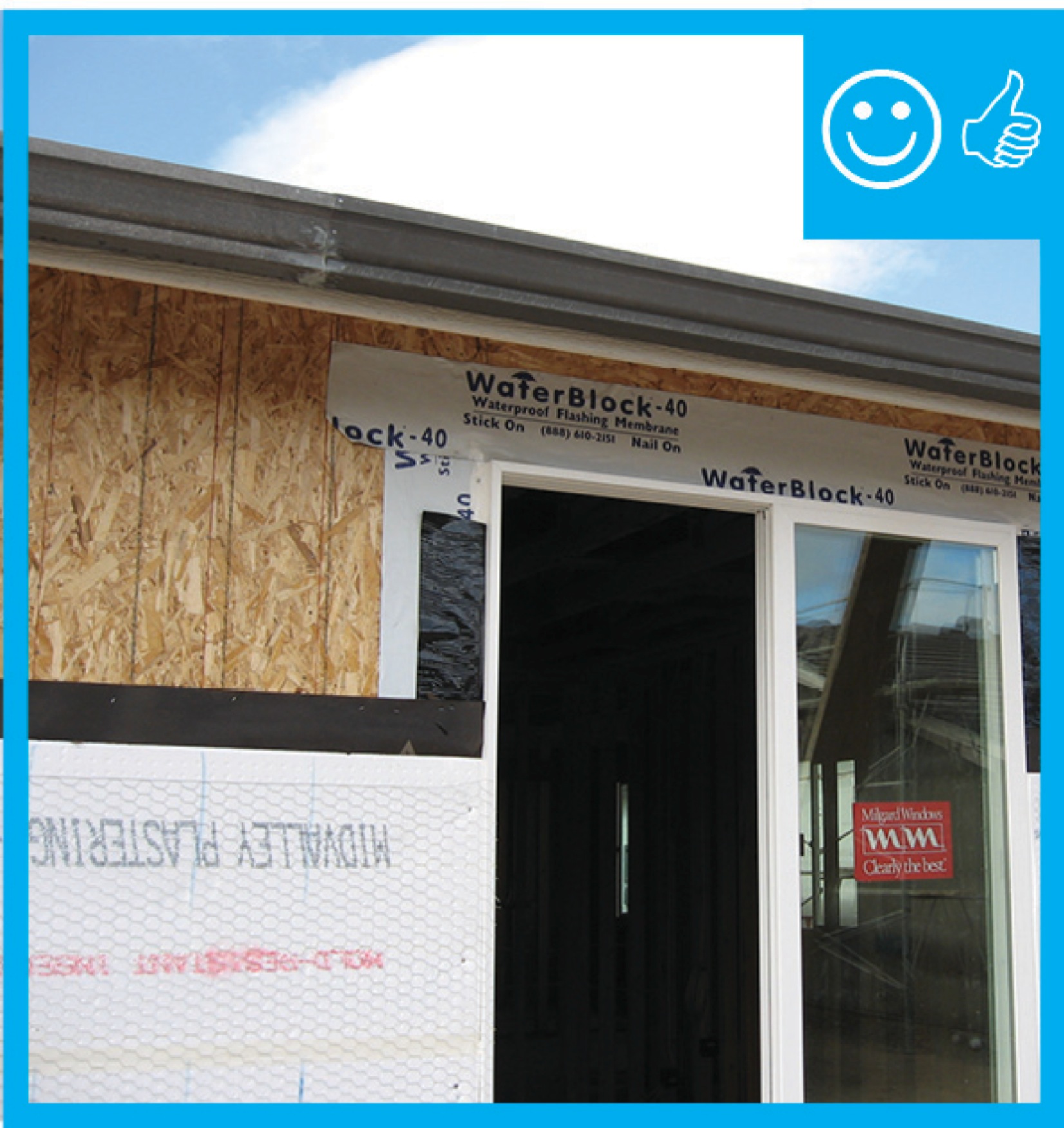
The rough openings for the windows are flashed with a paint-on flashing product then the windows are installed and additional flashing tape is installed over the flashing. Nail holes are sealed with caulk.
Image
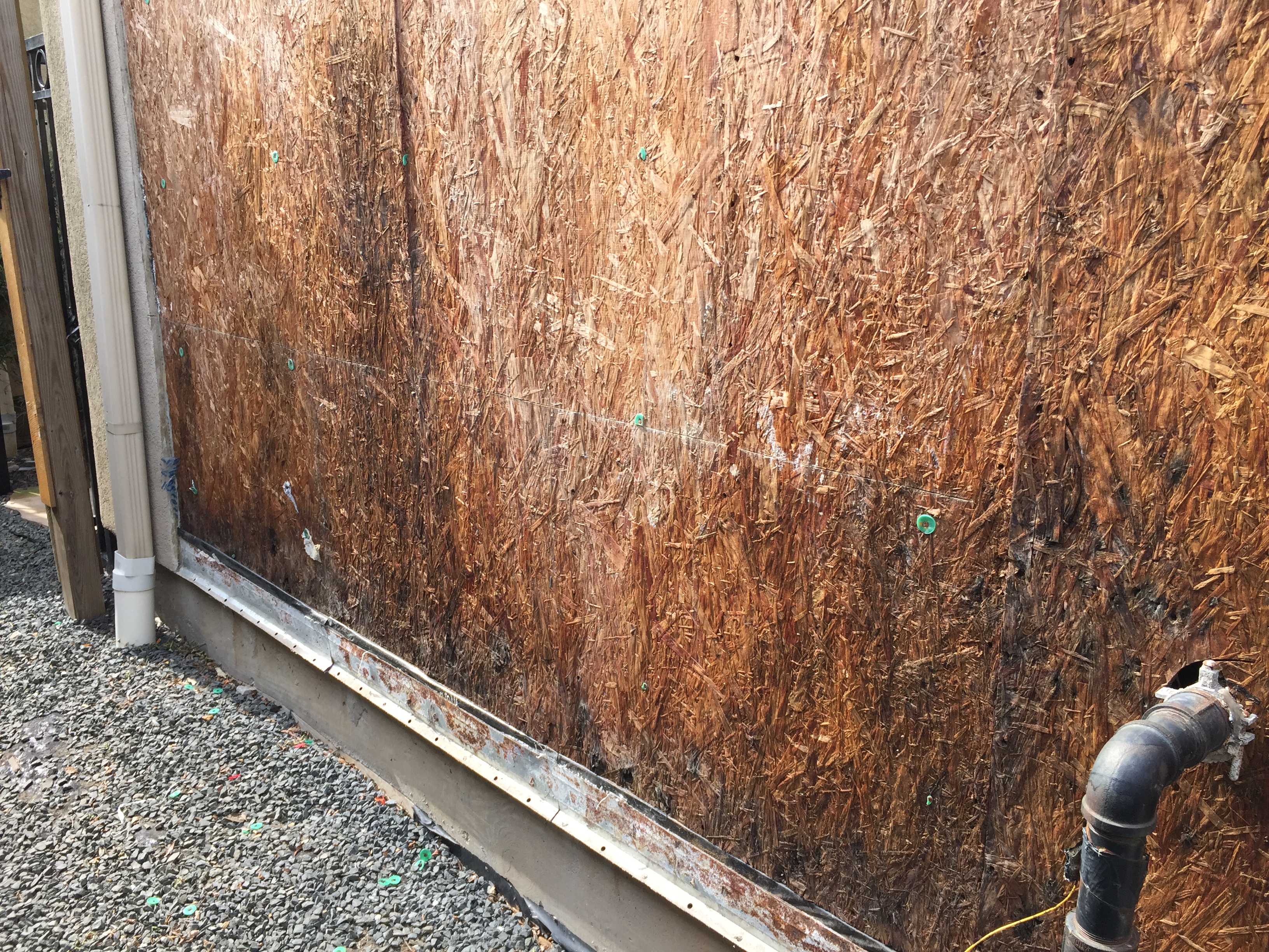
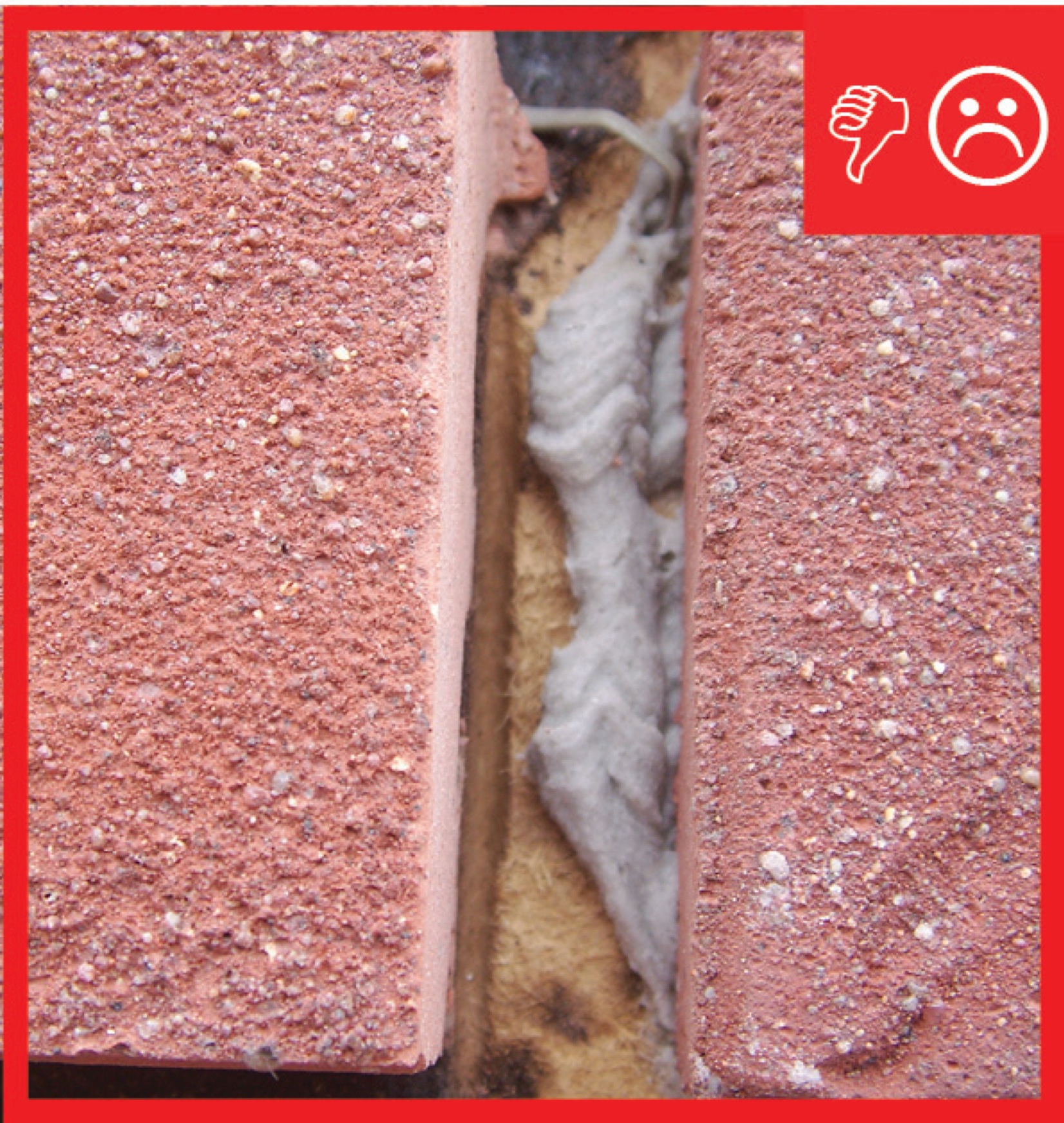
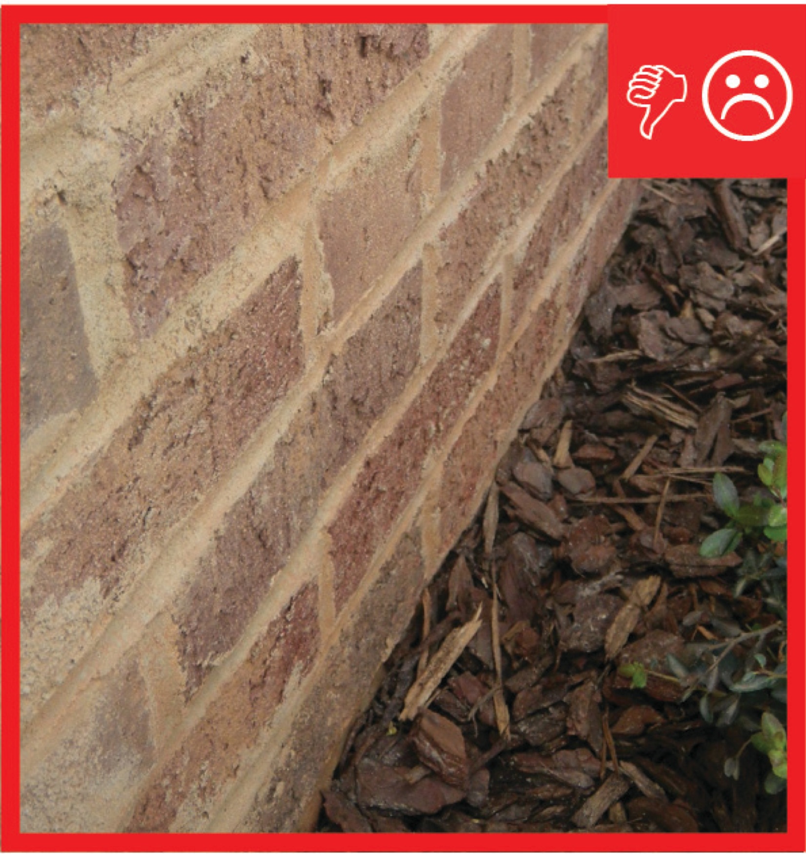
The sheathing has rotted because there was not a sufficient drainage gap behind the stucco cladding
Image
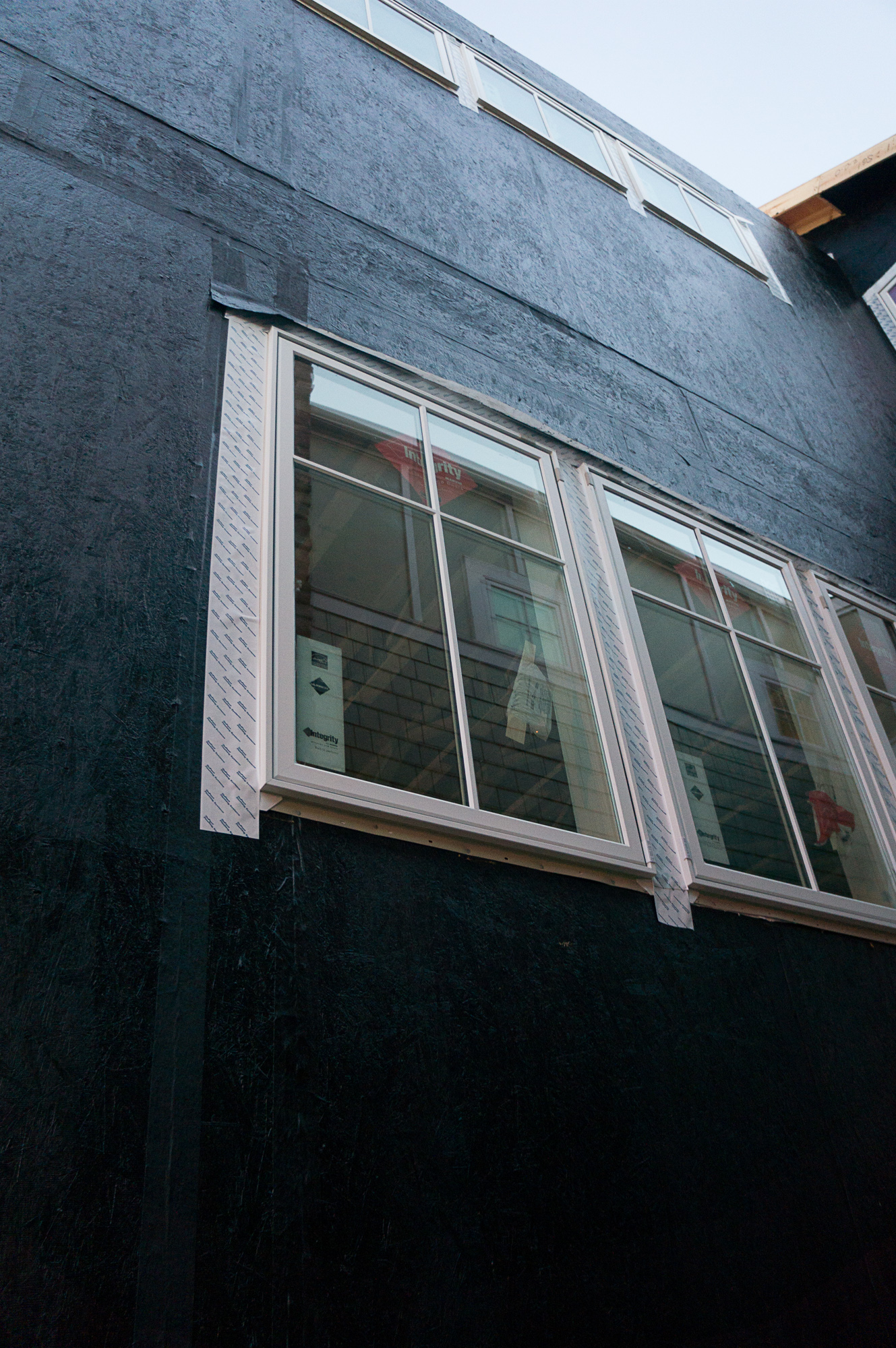
The tape window flashing here is integrated with the roller-applied weather-resistant barrier.
Image
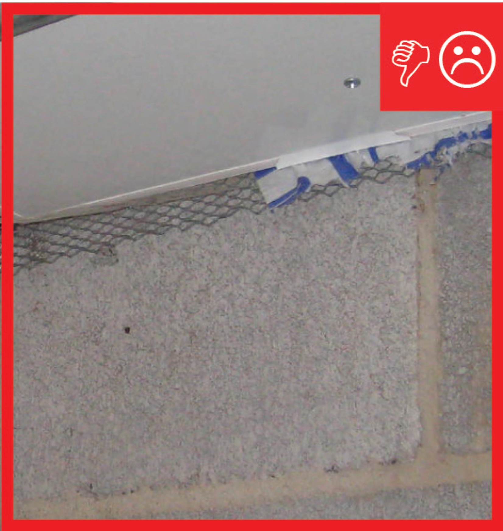
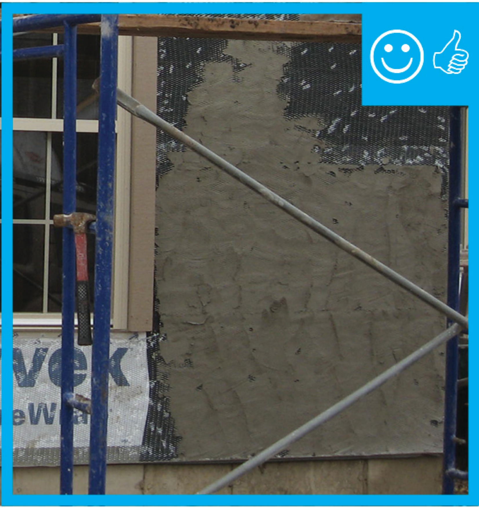
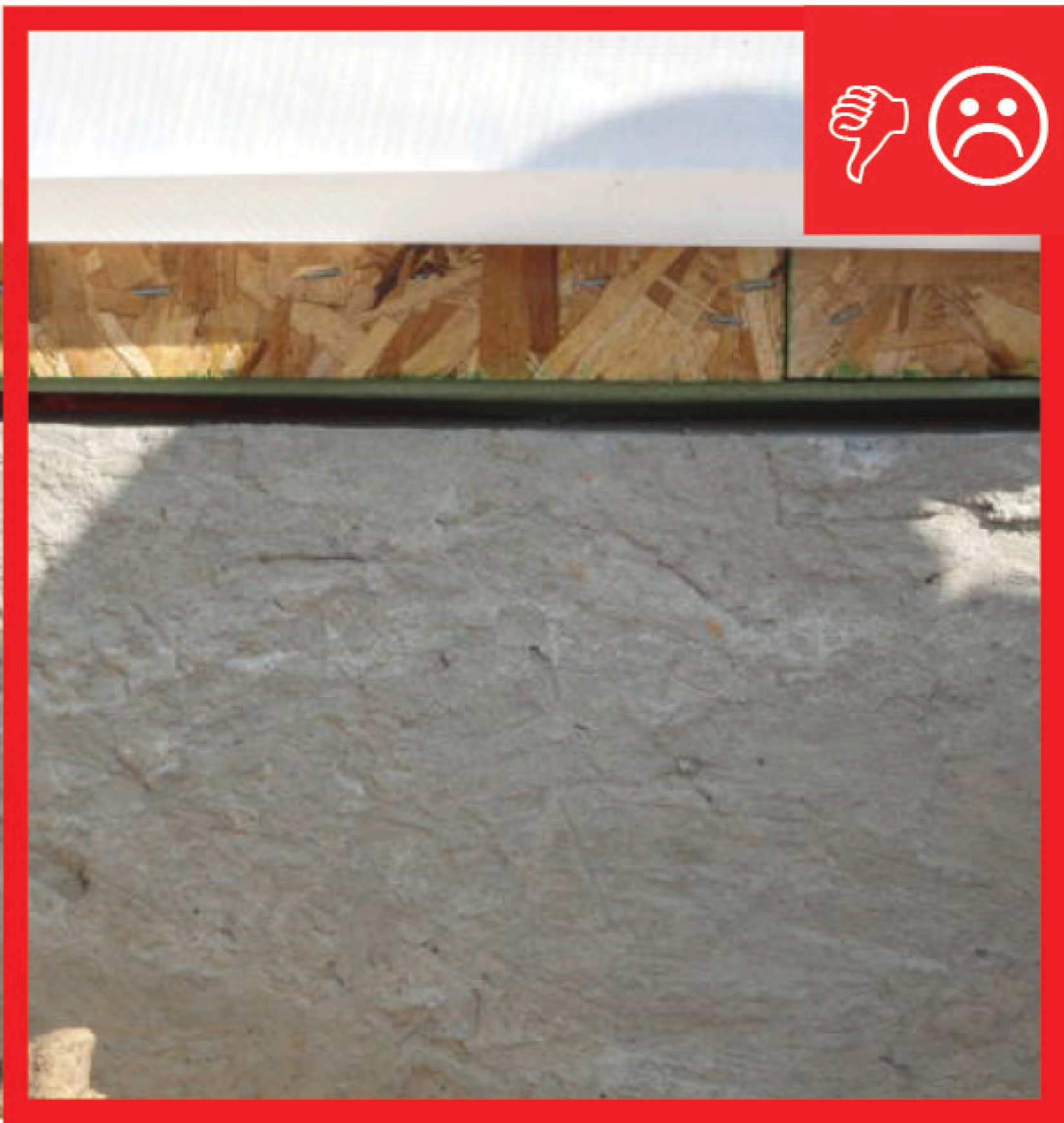
The water-resistant barrier, weep screed, and stucco lathe are not properly layered
Image
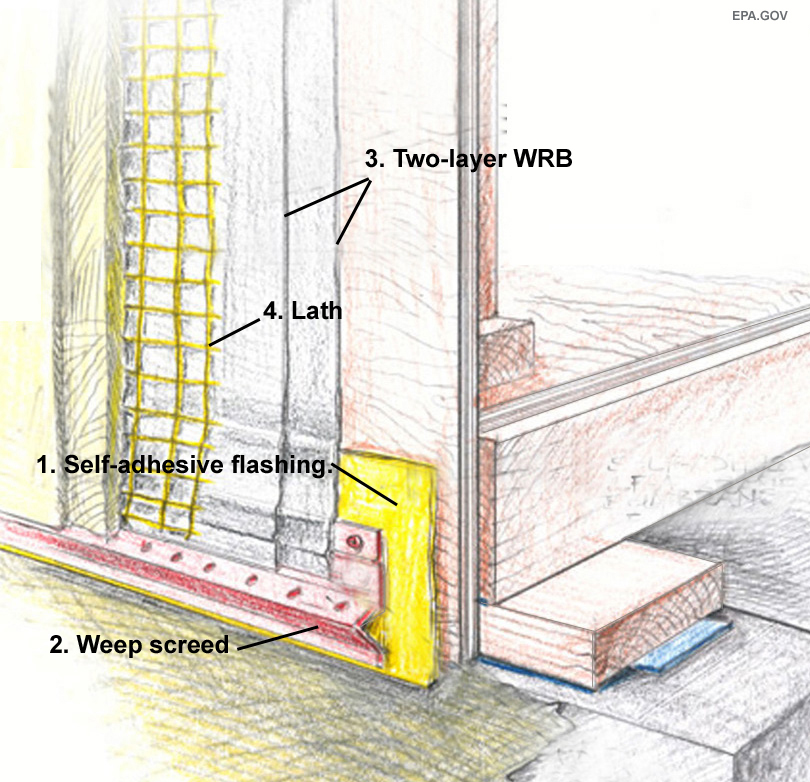
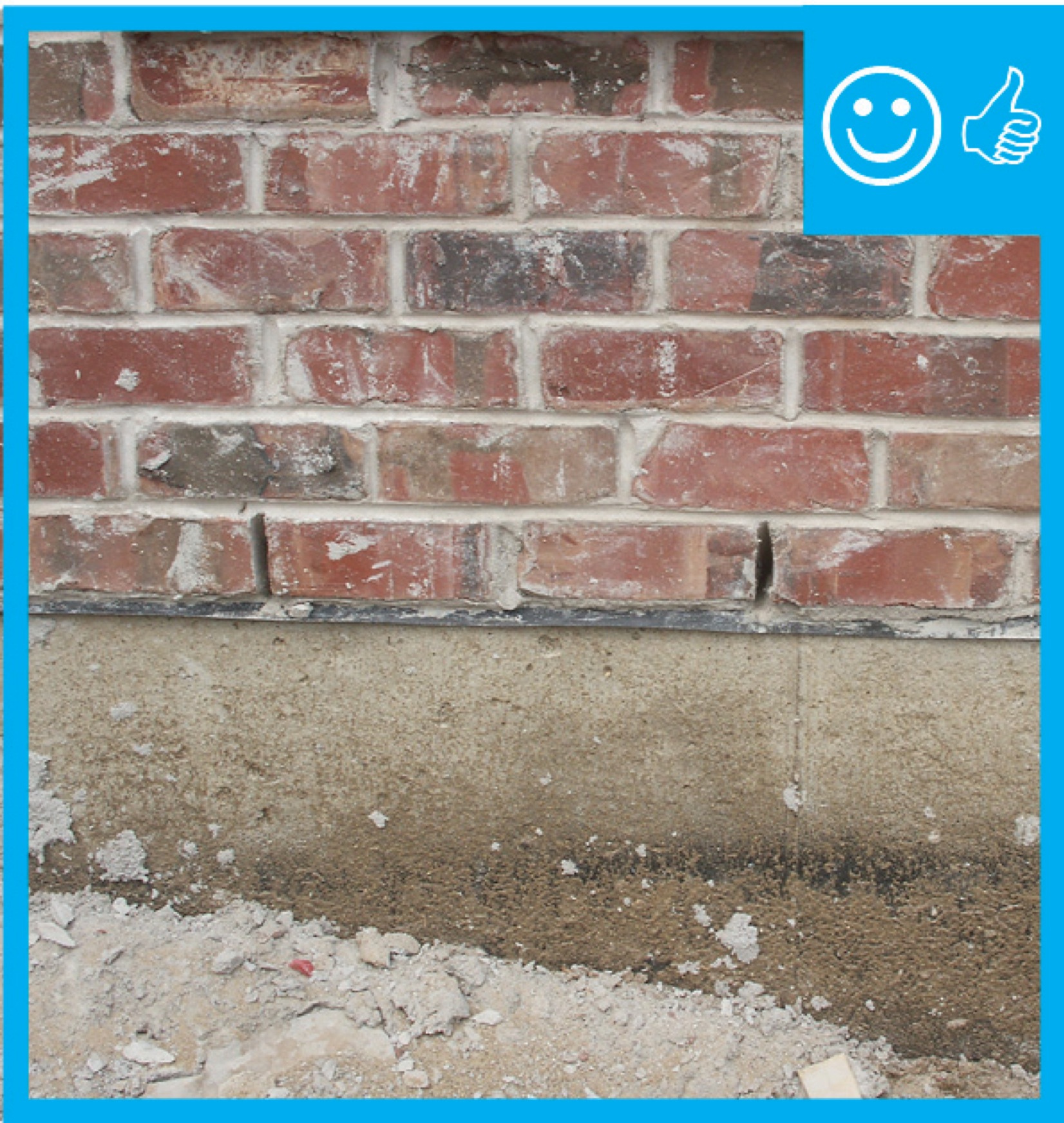
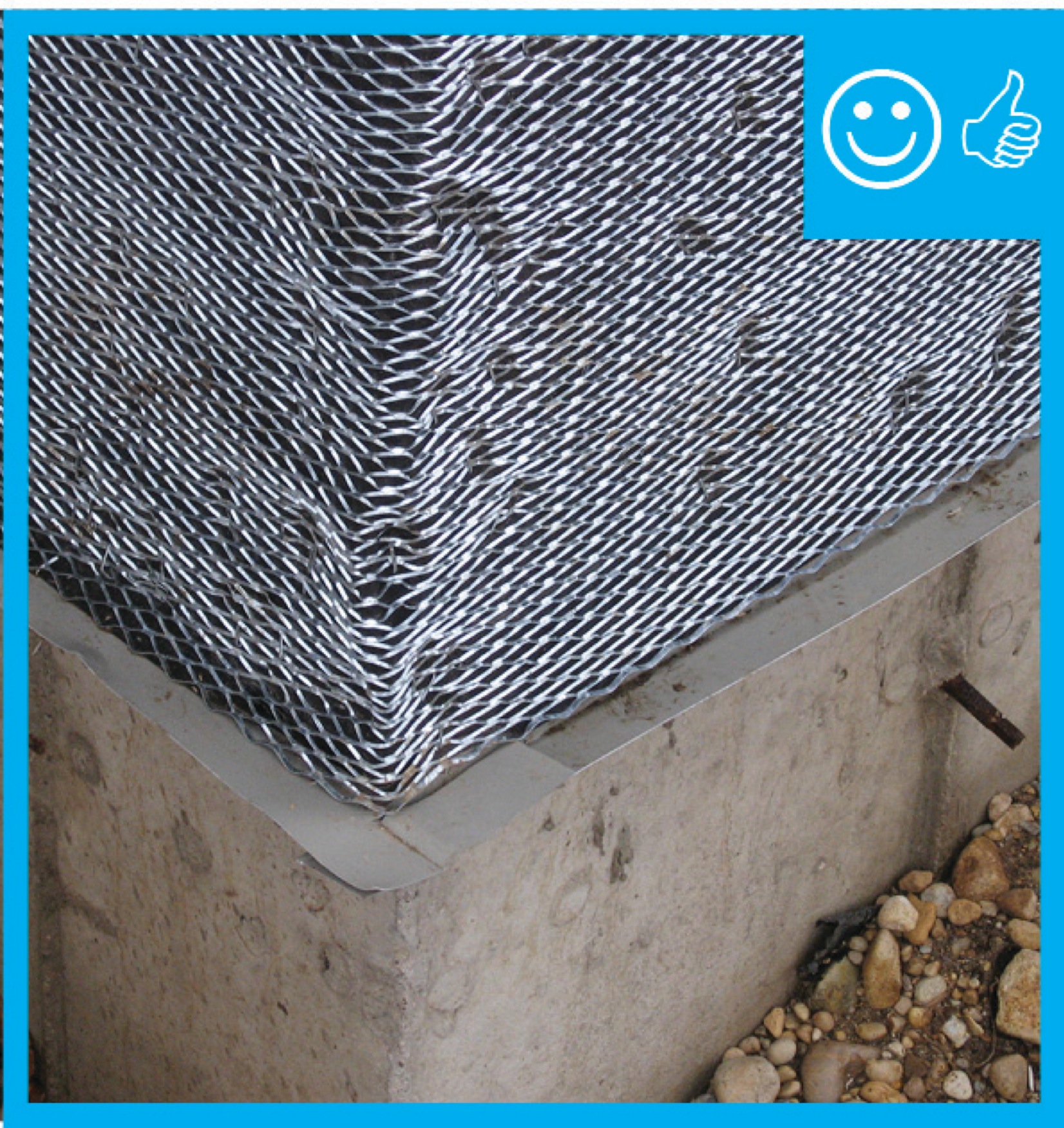
The water-resistant barrier, weep screed, and stucco lathe are properly layered and will create a complete drainage system
Image
Image
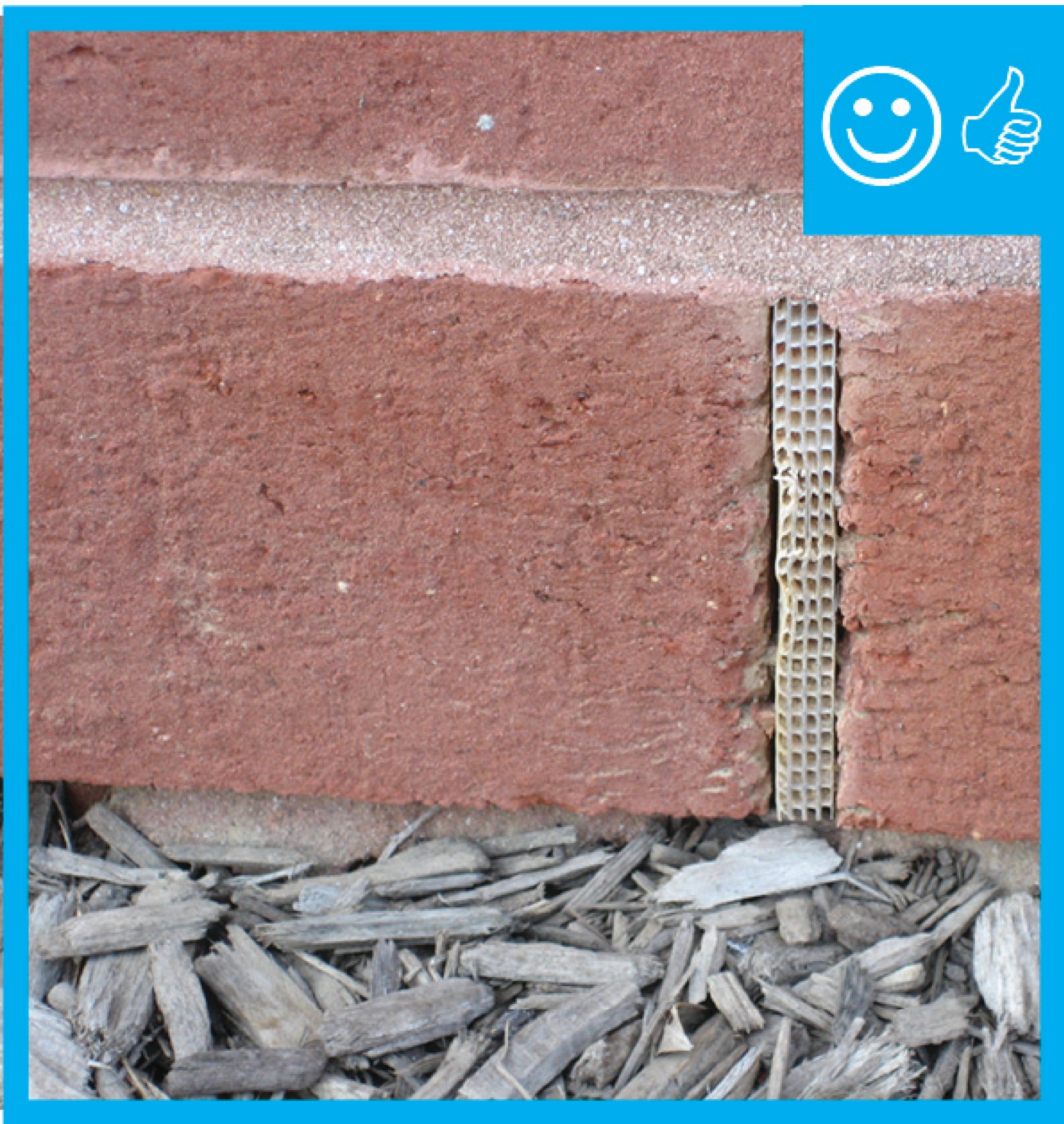
The weep holes are spaced at the correct distance to provide a complete drainage system
Image

Image
Image

The windows in this building are connected to the fully adhered water and air control layer using fluid-applied flashing
Image
Image
Image
Image
Image
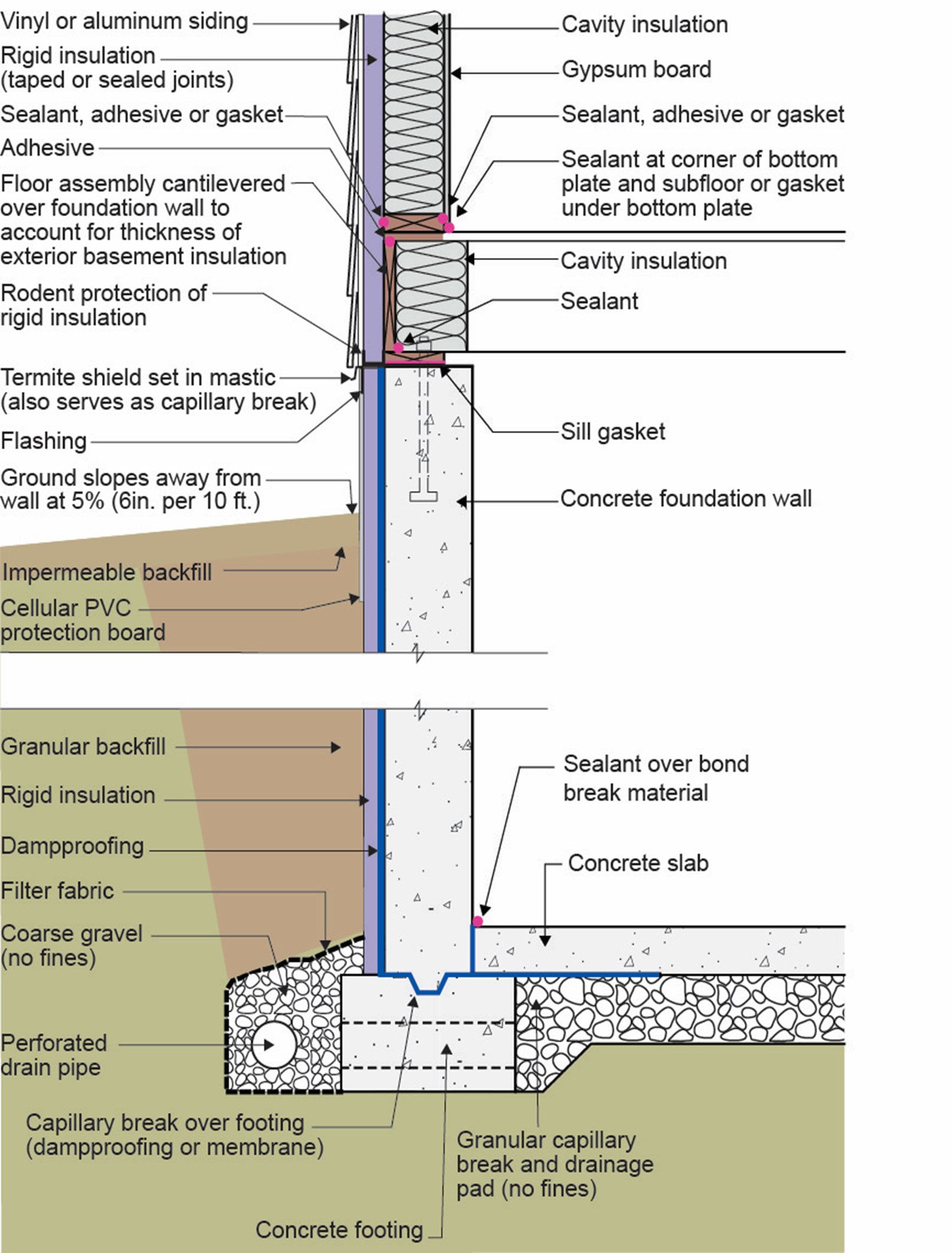
This basement is insulated on the exterior with rigid foam over dampproofing, with granular backfill and footing drains to facilitate drainage away from the foundation, a termite shield to protect from pests, and cellular PVC to protect the rigid foam.
Image
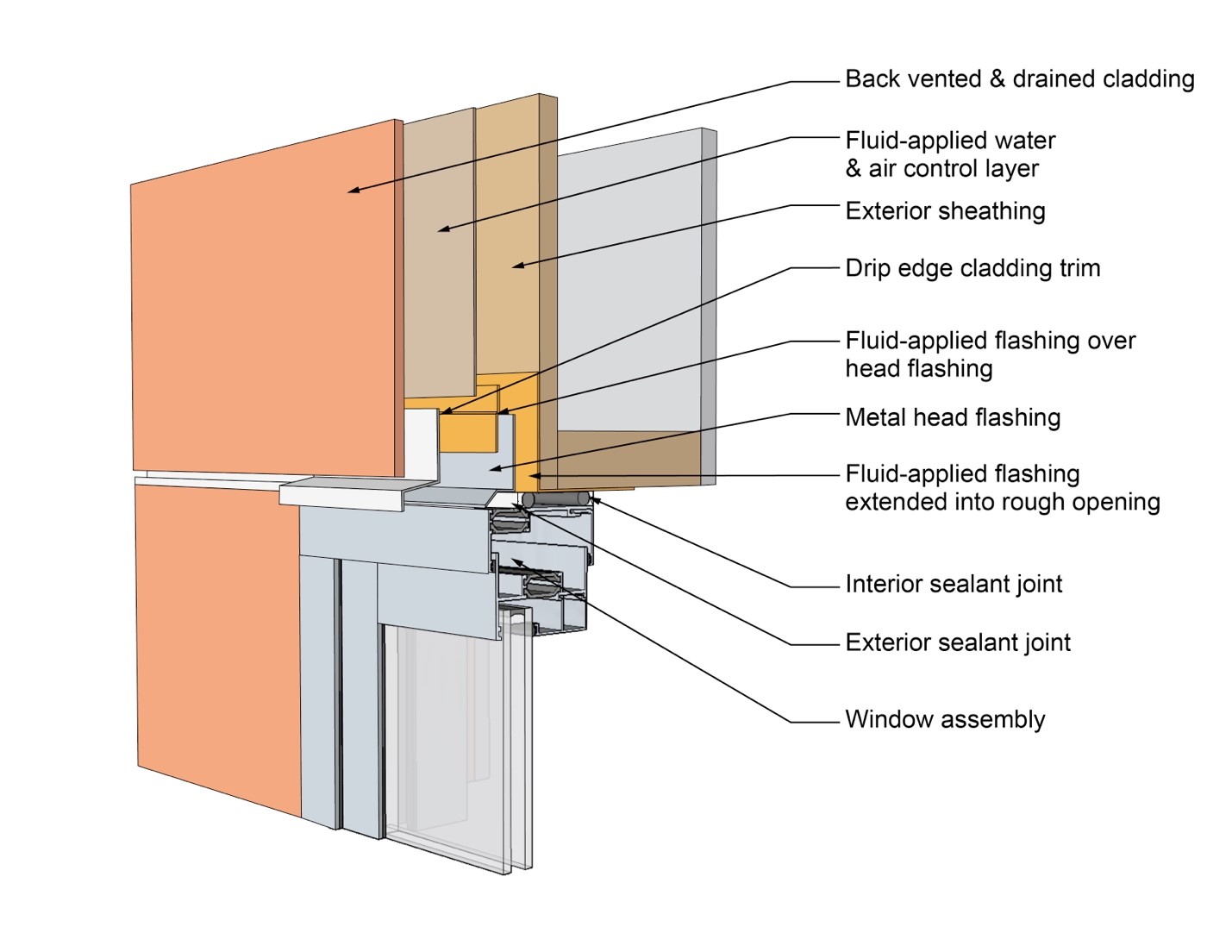
This drawing shows key head details for a window installation using a fluid-applied flashing on a wall with a fluid-applied water and air control layer
Image
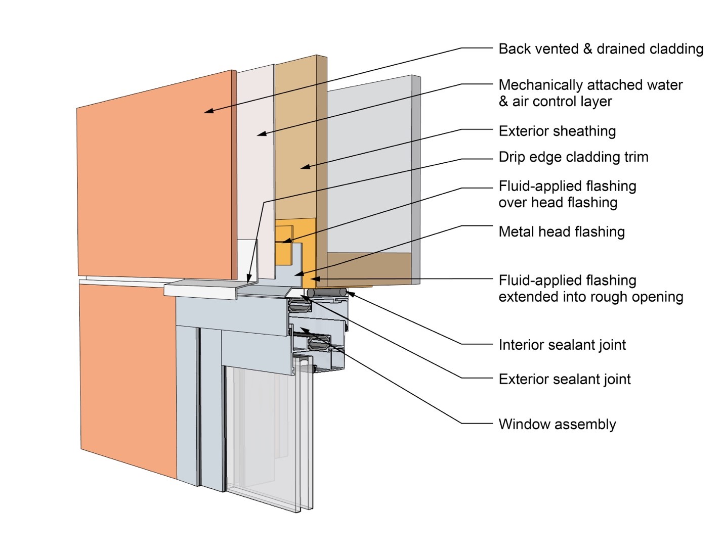
This drawing shows key head details for a window installation using a fluid-applied flashing on a wall with a mechanically attached water and air control layer
Image
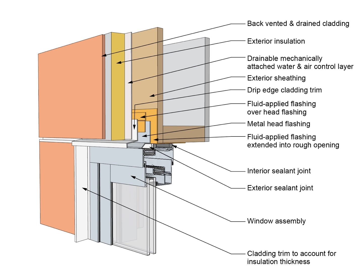
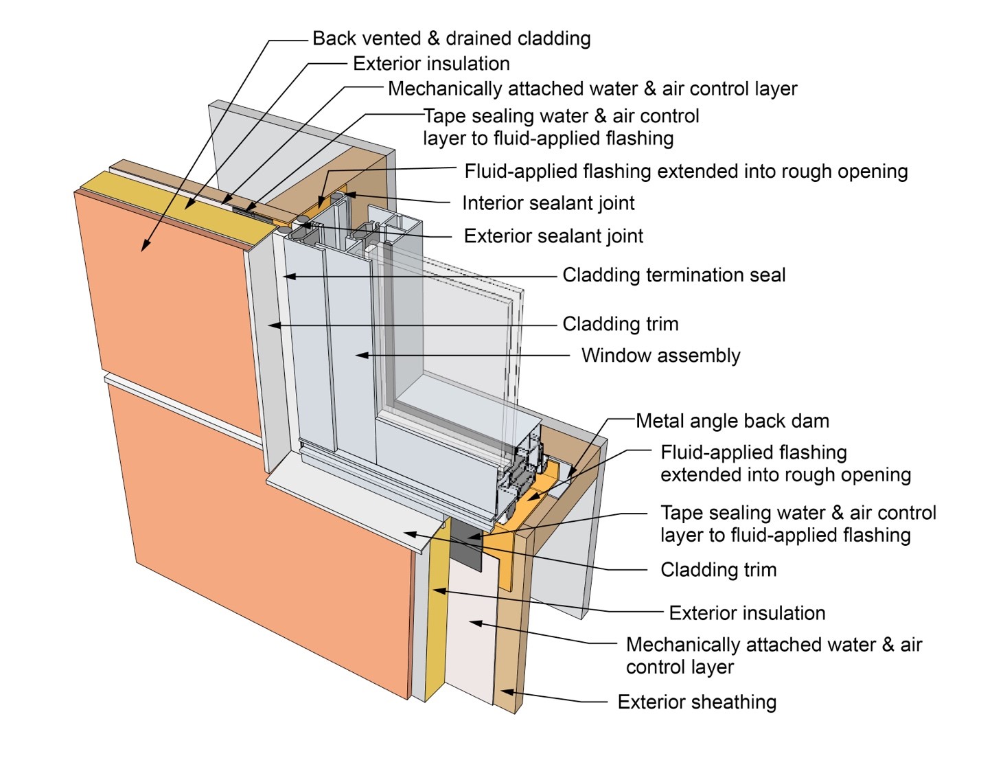
This drawing shows key head details for a window installation using a fluid-applied flashing on a wall with a mechanically attached water and air control layer and continuous insulation
Image
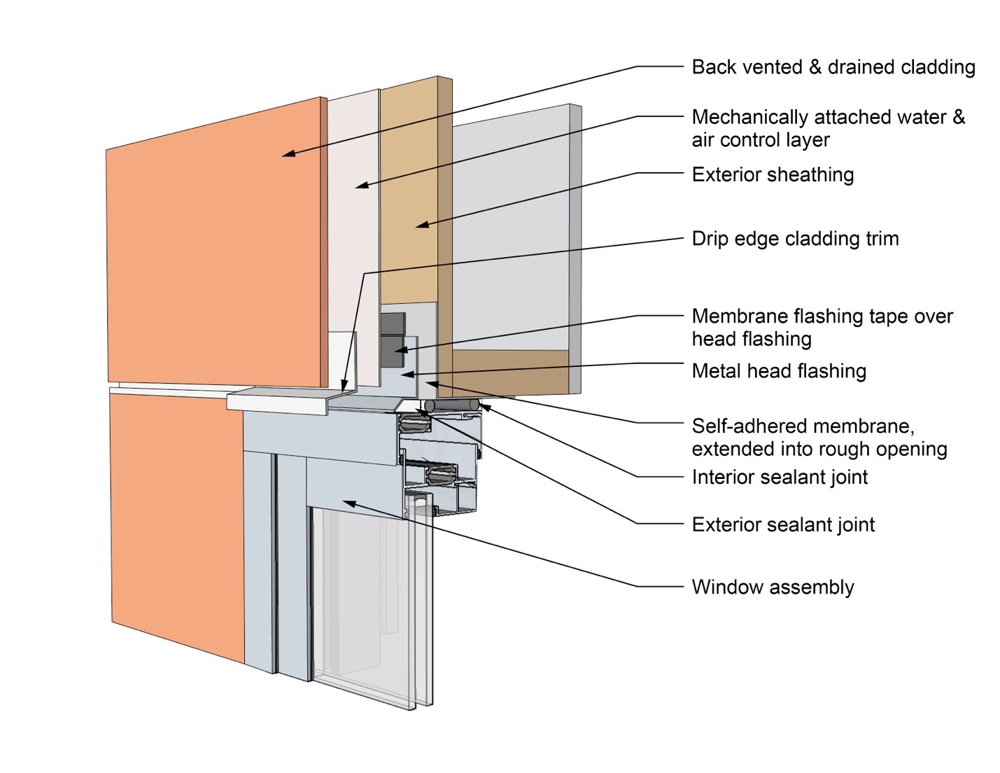
This drawing shows key head details for a window installation using a self-adhered membrane tape flashing on a wall with a mechanically attached water and air control layer
Image
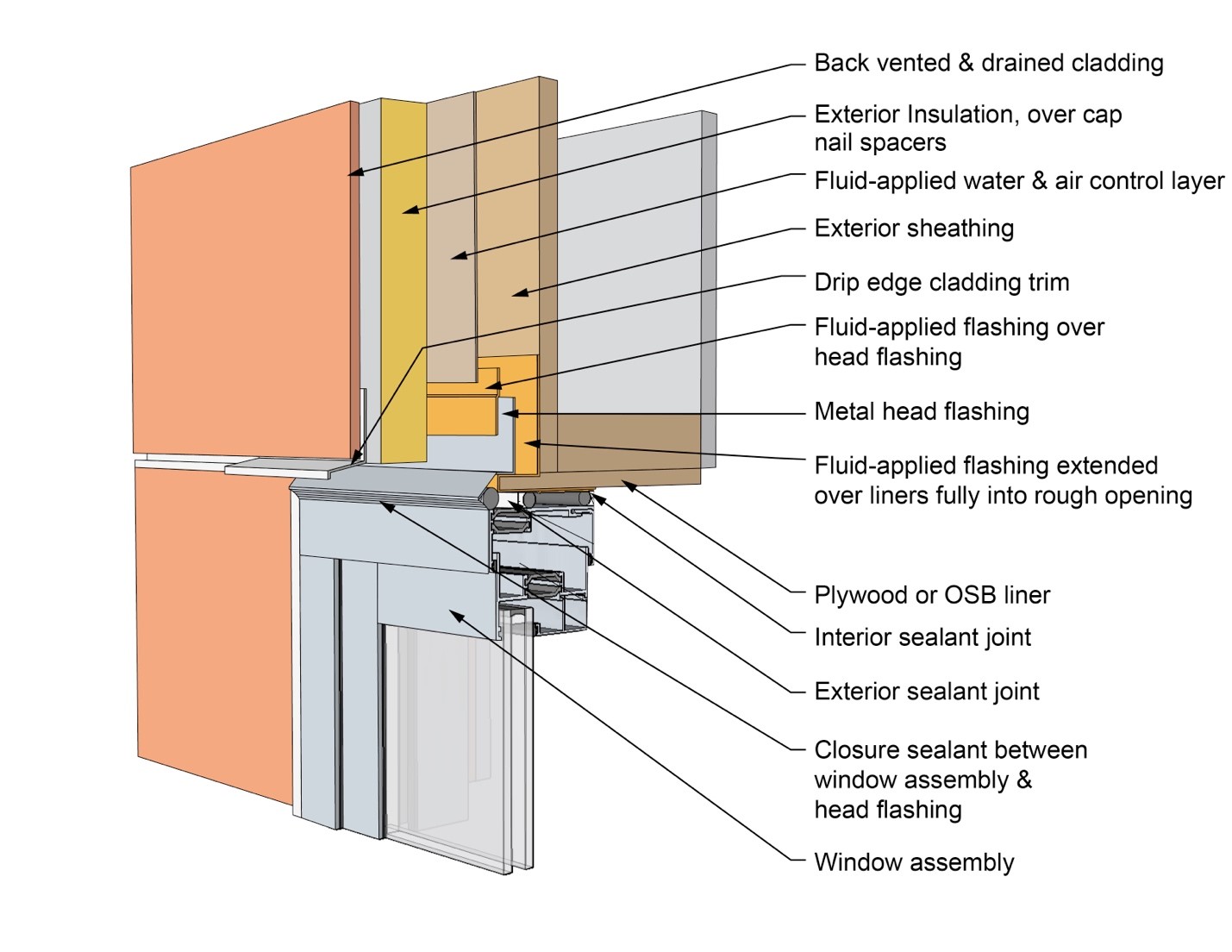
This drawing shows key head details for an “outie” window installation using a fluid-applied flashing on a wall with a fluid-applied water and air control layer and continuous insulation
Image
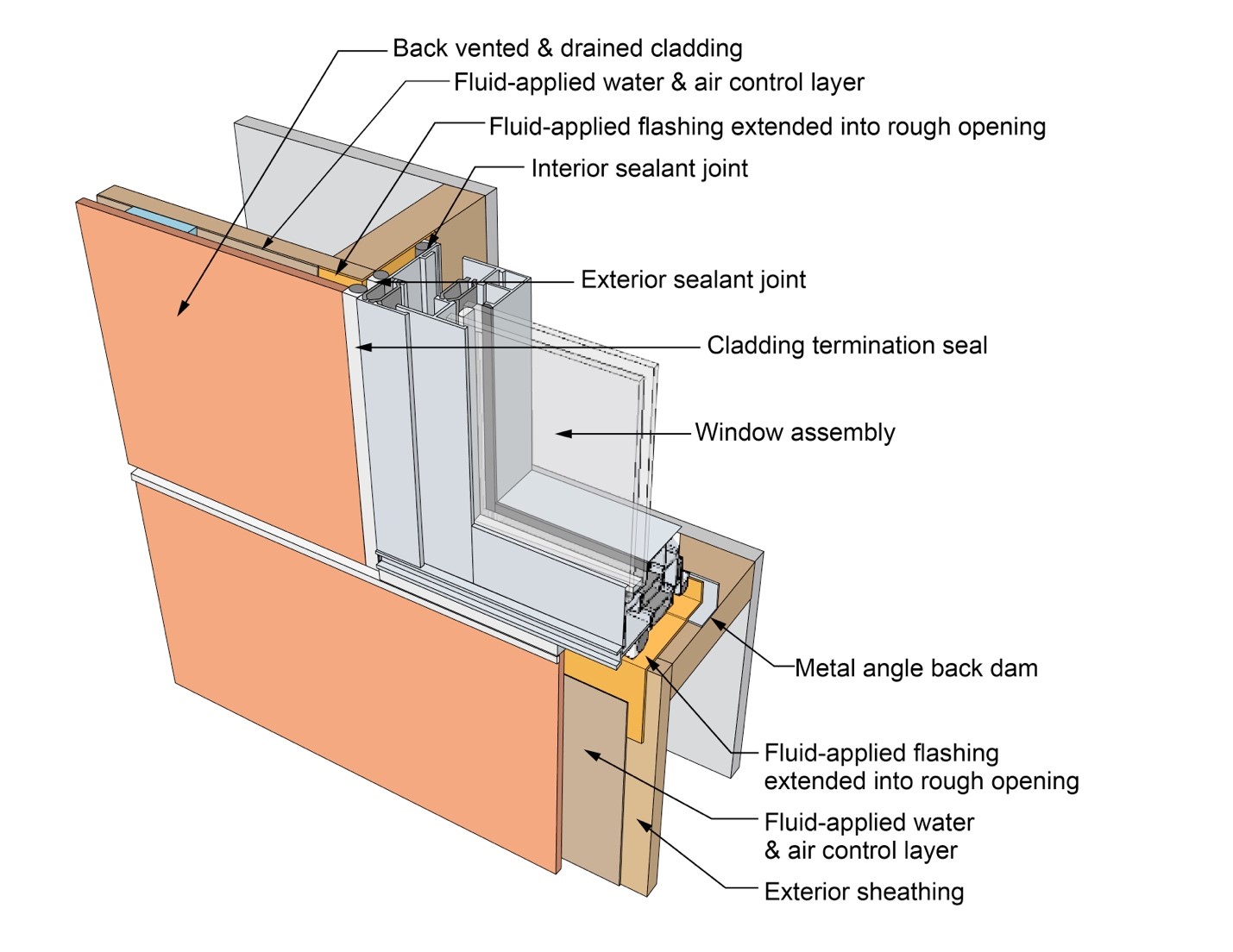
This drawing shows key jamb details for a window installation using a fluid-applied flashing on a wall with a fluid-applied water and air control layer
Image
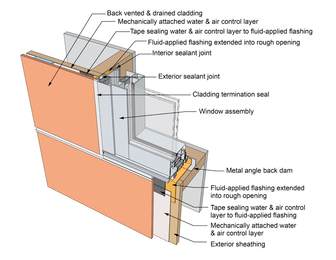
This drawing shows key jamb details for a window installation using a fluid-applied flashing on a wall with a mechanically attached water and air control layer
Image
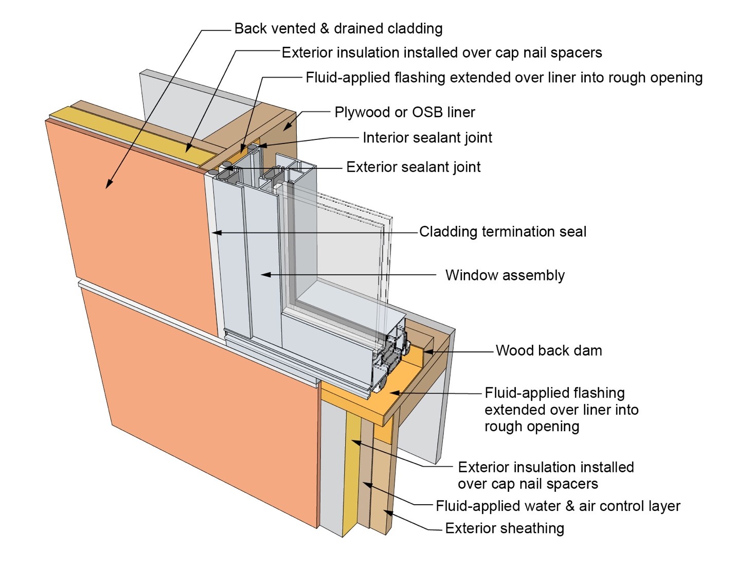
This drawing shows key jamb details for a window installation using a fluid-applied flashing on a wall with a mechanically attached water and air control layer and continuous insulation
Image
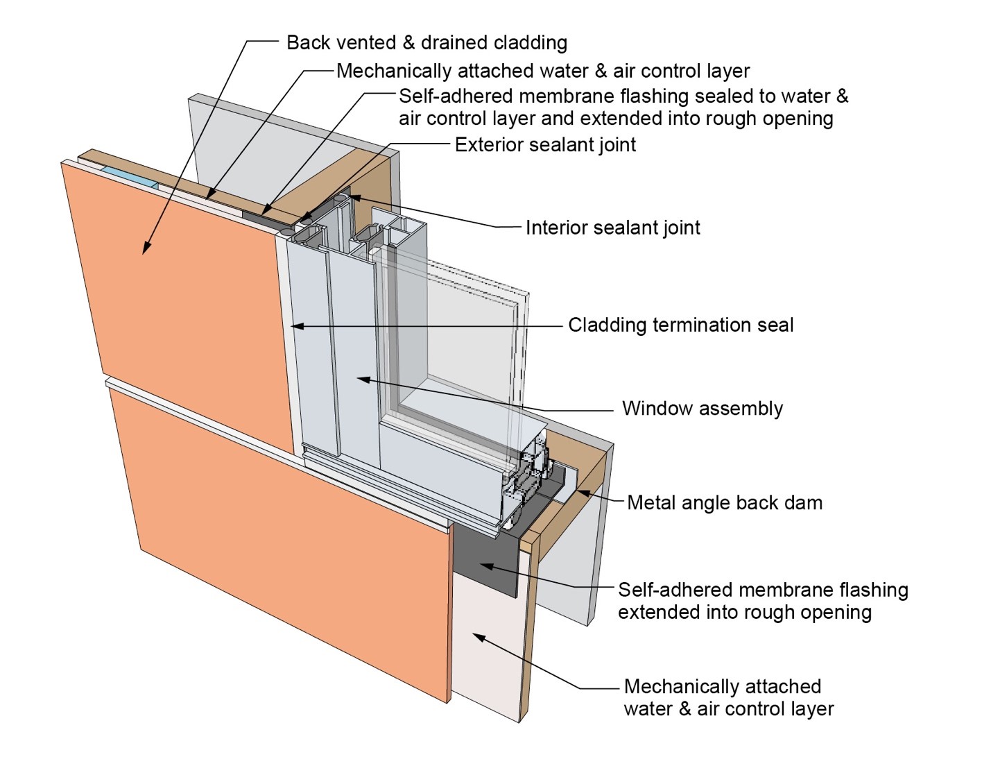
This drawing shows key jamb details for a window installation using a self-adhered membrane tape flashing on a wall with a mechanically attached water and air control layer
Image
This drawing shows key jamb details for an “outie” window installation using a fluid-applied flashing on a wall with a fluid-applied water and air control layer and continuous insulation